1
Industrial PCs applied in
/
Logistics and Warehouse
/
Heavy Duty
/
Fleet Management
/
Stationary and Automation
DLoG XMT 5 Series
Version 2.0
This manual contains a detailed description of the product and we have made every effort to make it as
accurate as possible. However, this is not a guarantee of the features or the functionality of the product.
We reserve the right to modify the contents of this document at any time and without prior notice.
Because we at DLoG are constantly striving to improve this product, we cannot guarantee that previous
or subsequent releases of the product will correspond in every respect with the product description
given in this manual.
DLoG GmbH assumes no liability for technical inaccuracies, typographic errors or faults in this
documentation. DLoG GmbH also assumes no liability for damages caused directly or indirectly by the
delivery, performance or usage of this material.
The software and hardware designations used in this documentation are in most cases also registered
trademarks and are thus subject to law.
Windows® is a registered trademark of Microsoft Corporation in the United States (US) and other
countries.
This documentation is protected by copyright. Duplication, in whole or in part, is not permitted without
prior written approval of DLoG GmbH!
Title of documentation:
User’s Manual DLoG XMT 5 Series
Documentation completed on:
October 27, 2011
Version:
V2.00
DAN
885250E.01
© Copyright 2010-2011
DLoG GmbH
Industriestraße 15
D-82110 Germering, Germany
All rights reserved
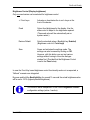
Technical customer support
If you experience technical difficulties, please
consult your distributor or contact the technical
services department at DLoG’s headquarters:
(+49) 89 / 41 11 91 0
www.dlog.com
Table of Content
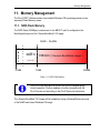
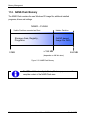
1. About this manual .................................................................................. 1 1.1. Please read documentation accompanying the product ........................................... 1 1.2. Current information on the internet............................................................................ 1 1.3. For qualified personnel .............................................................................................. 2 1.4. Keep this manual ....................................................................................................... 2 1.5. Design method .......................................................................................................... 2 1.5.1. 1.5.2. 1.5.3. 1.5.4. Risk of injury or death........................................................................................ 2 Danger of property damage .............................................................................. 3 Hints .................................................................................................................. 3 Additional design elements ............................................................................... 3 2. Basic safety guidelines.......................................................................... 4 2.1. Safety......................................................................................................................... 4 2.2. Initial operation of the device..................................................................................... 4 2.3. Power supply ............................................................................................................. 6 2.4. External devices ........................................................................................................ 6 2.5. Repairs only through DLoG GmbH ........................................................................... 6 2.6. WWAN Notes ............................................................................................................ 7 2.7. CE Marking ................................................................................................................ 7 2.8. RTTE Directive 1999/5/EC ........................................................................................ 8 2.7.1 Special rule/restriction ....................................................................................... 9 2.9. FCC user information .............................................................................................. 10 2.9.1. Interference declaration of the Federal Communications Commission .......... 10 2.9.2. Transmission of radio frequencies .................................................................. 11 2.10. Intended usage .................................................................................................... 12 3. Device description ............................................................................... 13 3.1. DLoG XMT 5 Models ............................................................................................... 13 3.2. Abbreviations used for devices and accessories .................................................... 13 3.3. Device type plate ..................................................................................................... 14 3.4. Technical data – System equipment ....................................................................... 15 3.4.1. CPU, Cache, RAM .......................................................................................... 15 3.4.2. 3.4.3. 3.4.4. 3.4.5. 3.4.6. 3.4.7. 3.4.8. 3.4.9. 3.4.10. 3.4.11. 3.4.12. 3.4.13. 3.4.14. 3.4.15. 3.4.16. 3.4.17. 3.4.18. 3.4.19. 3.4.20. 3.4.21. 3.4.22. Software ........................................................................................................... 15 Housing ............................................................................................................ 15 Display ............................................................................................................. 16 Touch screen (Standard + Option) .................................................................. 16 Audio interface for handset (Option – cannot be retrofitted) ........................... 16 Integrated speaker ........................................................................................... 17 I/O ports ........................................................................................................... 17 CAN 2.0 B (Option) .......................................................................................... 18 LCD port ...................................................................................................... 19 Front key interface ....................................................................................... 19 CompactFlash interface............................................................................... 19 SD /SDIO interface ...................................................................................... 19 Power supply ............................................................................................... 20 Ambient conditions ...................................................................................... 21 Test marks ................................................................................................... 21 Integrated WLAN antenna (WLAN option) .................................................. 22 Remote WLAN antenna(WLAN option) ....................................................... 22 WLAN module (option) ................................................................................ 23 GPS (option) ................................................................................................ 25 External magnetic Antenna for GPS, 5 m (Option) ..................................... 25 WWAN module (option) ............................................................................... 27 3.5. Device dimensions ................................................................................................... 29 3.5.1. DLoG XMT 5/7 ................................................................................................. 29 3.5.2. DLoG XMT 5/10 ............................................................................................... 32 3.6. VESA drill holes ....................................................................................................... 35 3.6.1. DLoG XMT 5/7 ................................................................................................. 35 3.6.2. DLoG XMT 5/10 ............................................................................................... 36 4. Unpacking the device ........................................................................... 37 4.1. Scope of delivery ..................................................................................................... 37 4.2. Packaging ................................................................................................................ 37 4.3. Returning your device .............................................................................................. 37 5. Initial operation ..................................................................................... 38 5.1. Wireless networks .................................................................................................... 38 5.1.1. WLAN............................................................................................................... 38 5.1.2. Summit Client Utility......................................................................................... 41 5.1.3. GPS ................................................................................................................. 42 5.1.4. GPS Information Applet................................................................................... 44 5.1.5. GPS Receiver Configuration (GPS Config)..................................................... 47 "Default GPS Settings" Fault ......................................................................................... 49 5.2. Protecting the TFT display from the memory effect ................................................ 54 5.3. Installing application software ................................................................................. 54 5.4. Calibrate touch screen............................................................................................. 54 5.5. External Connectors ................................................................................................ 55 5.5.1. DLoG XMT 5/7 ................................................................................................ 55 5.5.2. DLoG XMT 5/10 .............................................................................................. 56 5.6. Service-USB under the antenna cap ....................................................................... 57 5.7. Power supply units 12/24 VDC and 24/48 VDC ...................................................... 59 5.7.1. DC voltage supply connector .......................................................................... 60 5.8. Audio (Option) ......................................................................................................... 60 5.9. Connecting external devices ................................................................................... 61 5.9.1. USB Connection .............................................................................................. 61 5.9.2. COM Connections ........................................................................................... 61 5.10. Removing the protective film from the display .................................................... 63 6. Accessories .......................................................................................... 64 6.1. Keyboard ................................................................................................................. 64 6.1.1. SMALL keyboard ............................................................................................. 64 6.1.2. 24-key keypad ................................................................................................. 65 6.2. Mouse ...................................................................................................................... 65 6.3. USB stick ................................................................................................................. 65 6.4. Scanner ................................................................................................................... 65 6.5. WLAN cards ............................................................................................................ 65 6.6. SD memory cards .................................................................................................... 66 6.7. Adapter cables......................................................................................................... 66 7. Installation/Mounting ........................................................................... 67 7.1. Follow and retain the mounting instructions ............................................................ 67 7.2. Monting the device .................................................................................................. 68 7.2.1. Cooling through the supply of fresh air ........................................................... 68 7.3. Power supply ........................................................................................................... 69 7.3.1. Power supply 12/24 V and 24/48 V ................................................................. 69 7.3.2. Connecting cables ........................................................................................... 70 7.4. Vehicle applications (such as forklifts) ..................................................................... 70 7.4.1. Electrical installation ........................................................................................ 70 7.4.2. Position of the DLoG XMT 5 in the vehicle ...................................................... 72 7.5. Cable cover (splash guard)...................................................................................... 72 7.5.1. Protection class ............................................................................................... 72 7.6. Minimum distance to WLAN antenna ...................................................................... 72 8. Operation............................................................................................... 73 8.1. Touch Screen........................................................................................................... 73 8.2. Front keys and LEDs ............................................................................................... 74 8.2.1. 8.2.2. 8.2.3. 8.2.4. DLoG XMT 5/7 with 4 or 17 front keys ............................................................ 74 DLoG XMT 5/10 with 4 or 25 front keys .......................................................... 75 Brightness control ............................................................................................ 75 Function of front buttons and LED ................................................................... 76 9. Bootloader............................................................................................. 80 10. Operating System ............................................................................. 80 11. Memory Management ....................................................................... 81 11.1. NOR-Flash Memory ............................................................................................. 81 11.2. NAND-Flash Memory........................................................................................... 82 11.3. CE Image (Backup/Restore) ................................................................................ 83 11.3.1. 11.3.2. 11.3.3. 11.4. How to create an Image Backup file ............................................................ 83 How to restore an Image Backup file .......................................................... 86 Manual interaction (Generic-Boot-Mode) image ......................................... 89 Generic-BootMode CE Image operation ............................................................. 92 11.4.1. Reset of the OSInstall Flag.......................................................................... 93 12. DLoG neXt Config............................................................................. 95 12.1. Overview.............................................................................................................. 95 12.1.1. 12.1.2. 12.1.3. 12.1.4. 12.1.5. 12.2. “Options” menu .................................................................................................... 98 12.2.1. 12.2.2. 12.2.3. 12.2.4. 12.3. 15. About ......................................................................................................... 118 System Info ............................................................................................... 118 Make Report .............................................................................................. 123 DLoG Security Shell ....................................................................... 125 13.1. Overview............................................................................................................ 125 13.2. Configuration of the DLoG Security Shell ......................................................... 125 13.2.1. 13.2.2. 13.2.3. 13.2.4. 14. Change Mode ............................................................................................ 115 PIC Environment Æ Change EEPROM Data ........................................... 117 Exit............................................................................................................. 117 “Info” menu ........................................................................................................ 118 12.4.1. 12.4.2. 12.4.3. 13. Backlight Control ......................................................................................... 98 Set Front Keys........................................................................................... 100 Allocating Front Keys with Functions ........................................................ 104 Switch-off Automatic.................................................................................. 110 “Advanced” menu .............................................................................................. 115 12.3.1. 12.3.2. 12.3.3. 12.4. Display brightness, automatic switch-off etc. configuration ........................ 95 Dialogue in neXt Config.EXE in portrait or landscape format ..................... 95 Saving neXt Config.EXE settings ................................................................ 95 Starting neXt Config.EXE ............................................................................ 95 neXt Config Menu Bar ................................................................................. 97 DLoG Security Shell Features................................................................... 127 Administrator Password change \ reset .................................................... 128 “Retrieval parameter” Program ................................................................. 130 “Registry” Program Messages .................................................................. 131 DLoG Admin Tools ......................................................................... 132 14.1. Rotate Screen.................................................................................................... 132 14.2. Save Registry .................................................................................................... 133 Active-Sync (XP Professional) ...................................................... 134 15.1. Components Required (Software) ..................................................................... 134 15.2. Establishing Active-Sync Connection ................................................................ 134 16. Software / Driver Installations (.CAB Files) .................................. 135 16.1. CAB File Installation .......................................................................................... 135 16.2. CAB File De-Installation..................................................................................... 136 17. Storage Manager ControlPanel Applet ......................................... 137 18. Serial ports ...................................................................................... 138 19. 20. 18.1. COM1 Options ................................................................................................... 138 18.2. COM2 (option) ................................................................................................... 138 18.3. COM3 (option) ................................................................................................... 139 18.4. Cable length and ground loops .......................................................................... 139 Audio ............................................................................................... 140 19.1. Internal speaker ................................................................................................. 140 19.2. Handset (optional) ............................................................................................. 142 Touch-Screen .................................................................................. 143 20.1. Design ................................................................................................................ 143 20.1.1. 20.1.2. 21. 22. Standard: 4 wire touch screen ................................................................... 143 Optional: 5 wire touch screen suitable for sunlight .................................... 143 20.2. Resistance ......................................................................................................... 143 20.3. Operation ........................................................................................................... 144 20.4. Cleaning ............................................................................................................. 144 20.5. Storage and Handling ........................................................................................ 144 20.6. Fine Tuning ........................................................................................................ 145 Internal devices............................................................................... 146 21.1. CF WLAN/memory cards (option) ..................................................................... 146 21.2. Automatic Shutdown (option)............................................................................. 146 Common mistakes in usage .......................................................... 147 22.1. Power supply ..................................................................................................... 147 22.2. Powering up/down ............................................................................................. 147 22.3. Cable cover ........................................................................................................ 147 22.4. Mounting/Installation .......................................................................................... 147 22.5. Mobile application on vehicles........................................................................... 148 22.6. Using the touch screen...................................................................................... 149 23. Troubleshooting ............................................................................. 149 24. Maintenance .................................................................................... 150 24.1. Cleaning the housing ......................................................................................... 150 24.2. Touch screen cleaning ...................................................................................... 150 24.3. Cleaning cooling fins ......................................................................................... 150 25. Disposal .......................................................................................... 151 26. Return packing slip ........................................................................ 152 Index ............................................................................................................ 153 List of figures
Figure 3.1: DLoG XMT 5/7 (with optional mounting bracket) .......................................... 13 Figure 3.2: DLoG XMT 5/10 (with optional foot) .............................................................. 13 Figure 3.3: Device type plate XMT 5/7 ............................................................................. 14 Figure 3.4: Device type plate XMT 5/10 ........................................................................... 14 Figure 3.5: Speaker on the side of DLoG XMT 5 ............................................................. 17 Figure 3.6: Service USB port ............................................................................................ 18 Figure 3.7: Integrated antenna ......................................................................................... 22 Figure 3.8: Remote antenna ............................................................................................. 22 Figure 3.9: Dimensions DLoG XMT 5/7 front view ........................................................... 29 Figure 3.10: Dimensions DLoG XMT 5/7 side view .......................................................... 30 Figure 3.11: Dimensions DLoG XMT 5/7 top view ........................................................... 31 Figure 3.12: Dimensions DLoG XMT 5/10 front view ....................................................... 32 Figure 3.13: Dimensions DLoG XMT 5/10 side view ........................................................ 33 Figure 3.14: Dimensions DLoG XMT 5/10 top view ......................................................... 34 Figure 3.15: VESA drill holes on the DLoG XMT 5/7 ....................................................... 35 Figure 3.16: VESA drill holes on the DLoG XMT 5/10 ..................................................... 36 Figure 5.1: Summit Client Utility Icon ............................................................................... 38 Figure 5.2: SCU Taskbar Icon .......................................................................................... 39 Figure 5.3: Wi-Fi icon in the control panel ........................................................................ 39 Figure 5.4: SCU menu ...................................................................................................... 40 Figure 5.5: SCU menu – password entry ......................................................................... 40 Figure 5.6: SCU menu bar................................................................................................ 41 Figure 5.7: GPS, NMEA data stream, SERTEST9 ........................................................... 42 Figure 5.8: GPS Information Applet in the Control Panel ................................................. 44 Figure 5.9: GPS information display of current position ................................................... 45 Figure 5.10: GPS information display of signal strength of satellites ............................... 46 Figure 5.11: \Windows file ............................................................................................... 47 Figure 5.12: GPS Config XMT 5 ....................................................................................... 48 Figure 5.13: GPS Config: Settings successfully changed ................................................ 48 Figure 5.14: GPS Config: Settings could not be changed ................................................ 49 Figure 5.15: \Windows file ............................................................................................... 50 Figure 5.16: Advanced GPS Settings ............................................................................... 51 Figure 5.17: Perform HardReset ...................................................................................... 51 Figure 5.18: HardReset performed successfully .............................................................. 52 Figure 5.19: Exit GPS Settings ......................................................................................... 52 Figure 5.20: GPS module is not present .......................................................................... 53 Figure 5.21: Connectors DLoG XMT 5/7 .......................................................................... 55 Figure 5.22: Connector assignemet DLoG XMT 5/7 ........................................................ 55 Figure 5.23: Connectors DLoG XMT 5/10 ........................................................................ 56 Figure 5.24: Connector assignemet DLoG XMT 5/10 ...................................................... 56 Figure 5.25: Service USB under the openend antenna cap ............................................. 57 Figure 5.26: External connectors DLoG XMT 5, DC 12/24 V, 30 W ................................ 59 Figure 5.27: External connectors DLoG XMT 5, DC 24/48 V, 30 W ................................ 59 Figure 6.1: SMALL keyboard ............................................................................................ 64 Figure 6.2: 24-key keypad DLoG XMT 5 .......................................................................... 65 Figure 7.1: Position of the ground bolt ............................................................................. 71 Figure 8.1: DLoG XMT 5/7, 17 keys ................................................................................. 74 Figure 8.2: DLoG XMT 5/10, 25 keys ............................................................................... 75 Figure 11.1: NOR-Flash Memory ..................................................................................... 81 Figure 11.2: NAND-Flash Memory ................................................................................... 82 Figure 11.3: OS Install option symbol .............................................................................. 84 Figure 11.4: OS Install Settings dialogue ......................................................................... 84 Figure 11.5: System message before backup .................................................................. 85 Figure 11.6: Reboot after loading/saving the .IMG file ..................................................... 85 Figure 11.7: Backup file successfully saved on the SD-Card........................................... 86 Figure 11.8: OS Install option symbol .............................................................................. 86 Figure 11.9: OS Install Settings dialogue ......................................................................... 87 Figure 11.10: System message before restore ................................................................ 87 Figure 11.11: Error message: Image file is not compatible .............................................. 88 Figure 11.12: Automatic terminal reboot .......................................................................... 88 Figure 11.13: Reset OS Install dialogue ........................................................................... 89 Figure 11.14: Error message/OS Install ........................................................................... 90 Figure 11.15: Dialogue for manual OS Install Settings .................................................... 91 Figure 11.16: Dialogue OS Install Settings: Direct Install ................................................. 91 Figure 11.17: DLoG Security Shell dialogue .................................................................... 93 Figure 11.18: OS Install Status dialogue .......................................................................... 94 Figure 12.1: Symbol for started neXt Config.EXE in the taskbar ..................................... 95 Figure 12.2: Set-up dialogue for display brightness ......................................................... 98 Figure 12.3: Dialogue for front key settings .................................................................... 100 Figure 12.4: Front keys programming (Export) Success Message ................................ 101 Figure 12.5: Front keys programming (Export) ConfigFile view ..................................... 102 Figure 12.6: Front key programming (import) Success Message .................................. 103 Figure 12.7: Front key programming (Import - File access failed) Message .................. 103 Figure 12.8: Set-up dialogue for front key programming ................................................ 104 Figure 12.9: Set-up dialogue for front key programming (Option: “Text”) ...................... 106 Figure 12.10: Set-up dialogue for front key programming (Option: “Program”).............. 107 Figure 12.11: Set-up dialogue for front key programming (Option: “VK Codes”) ........... 108 Figure 12.12: Set-up dialogue for front key programming VK Code .............................. 109 Figure 12.13: Front key programming VK Codes - Invalid Input Message..................... 109 Figure 12.14: Set-up dialogue for Switch-off Automatic in neXt Config.EXE ................. 110 Figure 12.15: Dialogue: Advanced – Change Mode ...................................................... 115 Figure 12.16: Exit neXt Config - Warning ....................................................................... 117 Figure 12.17: Dialogue: Info – About .............................................................................. 118 Figure 12.18: Dialogue rubric: Info – System Info – Version .......................................... 119 Figure 12.19: Dialogue rubric: Info – System Info – Hardware ...................................... 119 Figure 12.20: Dialogue Rubric: Info – System Info – Expansion Boards ....................... 120 Figure 12.21: Dialogue Rubric: Info – System Info - Network ........................................ 120 Figure 12.22: Dialogue rubric: Info – System Info – Temperature ................................. 121 Figure 12.23: Dialogue Rubric: Info – System Info – PIC Info........................................ 122 Figure 12.24: Dialogue Rubric: Info – MakeReport – status message ........................... 123 Figure 12.25: Dialogue Rubrik: Info – MakeReport – Explorerview ............................... 123 Figure 12.26: Dialogue Rubrik: Info – MakeReport – Fileview ....................................... 124 Figure 13.1: DLoG Security Shell: Right click – Admin Tools – Enter Admin Mode ...... 125 Figure 13.2: DLoG Security Shell Dialogue: Enter Admin Password ............................. 126 Figure 13.3: DLoG Security Shell Dialogue: DLoG Security Shell Option ..................... 126 Figure 13.4: DLoG Security Shell Dialogue: Change \ Reset Password ........................ 128 Figure 13.5: DLoG Security Shell Dialogue: Enter Password ........................................ 129 Figure 13.6: DLoG Security Shell Service-Dialogue: Current Password........................ 130 Figure 13.7: DLoG Security Shell Service Dialogue: Set default: .................................. 130 Figure 13.8: DLoG Security Shell Service dialogue: “Restore standard password” ....... 131 Figure 13.9: DLoG Security Shell Service dialogue: Restart program ........................... 131 Figure 14.1: DLoG Admin Tools dialogue: Rotate Screen ............................................. 132 Figure 14.2: DLoG Admin Tools dialogue: Save Registry .............................................. 133 Figure 15.1: Active Sync dialogue: Explorer – Mobile Device ........................................ 134 Figure 16.1: CAB File De-Installation ............................................................................. 136 Figure 17.1: Storage Manager ControlPanel Applet ...................................................... 137 Figure 19.1: Speaker on the side of DLoG XMT 5/7 ...................................................... 140 Figure 19.2: Speaker volume configuration.................................................................... 140 Figure 19.3: Speaker Sounds Configuration .................................................................. 141 Figure 19.4: Speaker Configuration Audio Settings, Speaker ........................................ 141 Figure 19.5: Handset configuration, Control Panel menu Audio Settings ...................... 142 About this manual
1. About this manual
This manual has been designed to make using the DLoG XMT 5 as simple as possible
and provide expert assistance if problems should occur. It contains important information
on using the device safely, properly and efficiently. Adhering to the manual helps by
avoiding dangers, reducing repair costs and breakdown times and increasing the
reliability and lifespan of the DLoG XMT 5.
DLoG GmbH will not assume responsibility for any damage caused by the improper use
of the DLoG XMT 5 and/or in disregard of the instructions in this manual.
WARNING
Before transporting, assembling, and starting the DLoG XMT 5,
please read this manual carefully and follow all the safety guidelines
listed. Follow all Basic safety guidelines and the safety guidelines in
the individual chapters.
Within this manual, DLoG GmbH strives to provide all the information required for using
your DLoG XMT 5. However, because this is a versatile product that can be used in
many different scenarios, we cannot guarantee that the information contained in this
manual will cover every single aspect.
Should you require further information or if you have questions or issues needing
clarification, please contact your nearest DLoG agent or representative.
1.1. Please read documentation accompanying the product
Please take note of all documentation received for your industrial PC, such as safety
information, assembly instructions, etc.
1.2. Current information on the internet
Current manuals and additional useful information can be found on the internet at
www.advantech-dlog.com.
DLoG XMT 5
User’s Manual V2.00
1
About this manual
1.3. For qualified personnel
This manual was written for qualified personnel. The information is intended exclusively
to complement the expertise of qualified personnel , not to replace it.
1.4. Keep this manual
Please keep this manual in a safe place. It should always be at hand near the described
device.
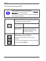
1.5. Design method
1.5.1. Risk of injury or death
This symbol indicates hazards that pose a risk to life and limb (such as contacting the
power supply):
The following levels apply, denoted by the keywords DANGER, WARNING, and
CAUTION:
DANGER
There is an immediate risk of death / serious injury.
WARNING
There is a possible risk of death / serious injury.
CAUTION
Mild injury is possible.
2
User’s Manual V2.00
DLoG XMT 5
About this manual
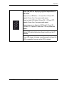
1.5.2. Danger of property damage
These tips warn you of possible property damage:
Caution:
Property
damage
This symbol warns you of any dangers or hazards that could
potentially cause damage to the terminal or system (such as
malfunctions, data loss, equipment damage, etc.).
1.5.3. Hints
This symbol indicates hints that help you to understand how to use
the product or the manual.
1.5.4. Additional design elements
Lists and instructions are indicated with bullet points, for example:
•
•
Power pack
Cable
Key display
Key names are shown in angle brackets: <F1>, <Ctrl>, <Insert>, <Home>, etc.
Menu options, commands, dialogue fields
Examples: In the Edit menu you will find the command Paste | Values.
Other methods for emphasis/References
Any other emphasized text elements are underlined.
References to other chapters in the manual are printed in italics.
DLoG XMT 5
User’s Manual V2.00
3
Basic safety guidelines
2. Basic safety guidelines
The DLoG XMT 5 Series was designed and built according to modern technology and
accepted safety regulations. However, the operation of the DLoG XMT 5 can endanger
personnel or third parties and cause damage to the device and other material assets
when for example the device is
•
•
•
•
mounted incorrectly
operated by untrained or uninformed personnel.
operated and maintained incorrectly.
not operated according to the intended usage
The operator commitments in regards to safety (accident prevention regulations, work
protection) are to be followed.
2.1. Safety
In order to prevent injury and damage, please read and observe the following safety
guidelines prior to assembly and commissioning. The manufacturer assumes no liability
for any and all damages that can be attributed to non-compliance with these guidelines.
2.2. Initial operation of the device
Area of application: not for use in life-support systems or critical safety systems
The device is not designed for use in life-support systems or critical safety systems
where system malfunction can lead to the direct or indirect endangerment of human
life. The operator shall take full responsibility for using the device in these situations.
The device cannot be used in combination with safety functions for machines and
equipment which have to conform to the requirements of EN 954-1.
4
User’s Manual V2.00
DLoG XMT 5
Basic safety guidelines
Risk of injury during transit or installation
The unit could fall during transit or installation and cause injury. Always ensure that
there are two persons available when installing or removing the device.
Selecting location: Consider type of IP protection and permissible environmental
temperature
The environmental conditions at the installation site must be such
-
that the type of IP protection for the device is sufficient.
-
that the permissible environmental temperature for the device is not fallen short of
or exceeded.
The type of IP protection of your DLoG industrial PCs and the temperature ranges are
found in section 3.4 Technical data – System equipment
Supply of fresh air – avoid overheating the unit
The DLoG XMT 5 is based on a passive cooling concept. As a result, the waste heat
which is produced inside the device is emitted over the surface of the housing. For this
system to function properly, sufficient fresh air circulation is required. Never install the
system in a closed environment where the cooling air is unable to dissipate
accumulated heat to the outside.
If the DLoG XMT 5 is not able to draw in fresh cooling air, this may cause overheating
and severe damage to the unit.
The maximum allowed ambient temperature for the system needs to be taken into
account for the concrete application area.
Install an easily accessible disconnecting device
The device is not supplied with a disconnector (switch) that can be accessed
externally. The power supply connector is therefore used as a disconnector.
Therefore it needs to be easily accessible.
Laying power supply cables – observe the local installation regulations
The power supply cables must be laid in accordance with the applicable local
installation regulations.
Ensure that no persons are injured in case the mounting bracket breaks
The DLoG XMT 5 may in no case be installed in such a way that persons can be
injured during a breaking of the mounting bracket (e.g. fatigue break).
If the device is mounted in a place where people can be injured if the bracket should
break, appropriate safety measures must be put in place (e.g. install a security cable
in addition to the device bracket).
DLoG XMT 5
User’s Manual V2.00
5
Basic safety guidelines
2.3. Power supply
Operation in an emergency – immediately disconnected the device from the
power supply
In case of emergency (such as damage to the power cable, or housing, or ingress of
liquid or other foreign bodies), the device must be disconnected immediately from the
power supply. Contact technical support staff at once.
If, after replacement, the fuse fed by the internal power supply blows again, the device
must be sent in for servicing immediately.
Do not use the DLoG XMT 5 when a cable or plug is damaged. Have the damaged
parts replaced immediately!
Data cables must never be connected or disconnected during an electrical storm.
2.4. External devices
Before connecting or disconnecting peripheral devices (exception: USB devices), the
DLoG XMT 5 must be disconnected from the power supply. Otherwise, this could
seriously damage both the DLoG XMT 5 and the connected devices!
Make sure that external peripheral devices with their own power supply are switched
on at the same time or after you start the DLoG XMT 5.
If this is not possible, please ensure that the DLoG XMT 5 is adequately protected
from power leakage caused by an external device.
2.5. Repairs only through DLoG GmbH
As a rule, never carry out repairs on the device yourself. Always contact DLoG’s
technical support and send in your unit for repair if necessary.
On the back of the DLoG XMT 5 you will find the device’s type plate which has
important information about the device which you must quote for technical service. It
provides important information about the configuration and manufacture of the device
in abbreviated form.
Always provide technicians with the full model name and serial number.
6
User’s Manual V2.00
DLoG XMT 5
Basic safety guidelines
2.6. WWAN Notes
If your Industrial PC is equipped with WWAN:
• Do not operate the Industrial PC in the presence of flammable gases or fumes.
• Switch off the Industrial PC when you are near petrol stations, fuel depots,
chemical plants or where blasting operations are in progress.
• Operation of any electrical equipment in potentially explosive atmospheres can
constitute a safety hazard.
• Road safety comes first! Do not use your Industrial PC when driving a vehicle,
unless it is securely mounted in a holder for speakerphone operation.
2.7. CE Marking
Remark for CE class A products: Class A products may be used in residential
environment but with the condition that the end user is informed about the possible
consequence with a warning information in the user manual:
Warning! This is a class A device. This equipment may cause interference in a residential
installation. In this case the user is encouraged to perform appropriate measures to
correct the interference.
DLoG XMT 5
User’s Manual V2.00
7
Basic safety guidelines
2.8. RTTE Directive 1999/5/EC
With regard to the RTTE Directive 1999/5/EC the statements in the declaration of
conformity for the DLoG XMT 5 apply.
Česky
[Czech]:
Dansk
[Danish]:
Deutsch
[German]:
Eesti
[Estonian]:
English:
Español
[Spanish]:
Ελληνική
[Greek]:
Français
[French]:
Íslenska
[Icelandic]:
Italiano
[Italian]:
Latviski
[Latvian]:
Lietuvių
[Lithuanian]:
Nederlands
[Dutch]:
Malti
[Maltese]:
Magyar
[Hungarian]:
8
Toto zařízení je v souladu se základními požadavky a ostatními
odpovídajícími ustanoveními Směrnice 1999/5/EC.
Dette udstyr er i overensstemmelse med de væsentlige krav og
andre relevante bestemmelser i Direktiv 1999/5/EF.
Dieses Gerät entspricht den grundlegenden Anforderungen und
den weiteren entsprechenden Vorgaben der Richtlinie
1999/5/EU.
See seade vastab direktiivi 1999/5/EÜ olulistele nõuetele ja
teistele asjakohastele sätetele.
This equipment is in compliance with the essential requirements
and other relevant provisions of Directive 1999/5/EC.
Este equipo cumple con los requisitos esenciales asi como con
otras disposiciones de la Directiva 1999/5/CE.
Αυτός ο εξοπλισµός είναι σε συµµόρφωση µε τις ουσιώδεις
απαιτήσεις και άλλες σχετικές διατάξεις της Οδηγίας
1999/5/EC.
Cet appareil est conforme aux exigences essentielles et aux
autres dispositions pertinentes de la Directive 1999/5/EC.
Þetta tæki er samkvæmt grunnkröfum og öðrum viðeigandi
ákvæðum Tilskipunar 1999/5/EC.
Questo apparato é conforme ai requisiti essenziali ed agli altri
principi sanciti dalla Direttiva 1999/5/CE.
Šī iekārta atbilst Direktīvas 1999/5/EK būtiskajām prasībām un
citiem ar to saistītajiem noteikumiem.
Šis įrenginys tenkina 1999/5/EB Direktyvos esminius
reikalavimus ir kitas šios direktyvos nuostatas.
Dit apparaat voldoet aan de essentiele eisen en andere van
toepassing zijnde bepalingen van de Richtlijn 1999/5/EC.
Dan l-apparat huwa konformi mal-ħtiġiet essenzjali u lprovedimenti l-oħra rilevanti tad-Direttiva 1999/5/EC.
Ez a készülék teljesíti az alapvető követelményeket és más
1999/5/EK irányelvben meghatározott vonatkozó
rendelkezéseket.
User’s Manual V2.00
DLoG XMT 5
Basic safety guidelines
Norsk
Norwegian]:
Polski
[Polish]:
Português
[Portuguese]:
Slovensko
[Slovenian]:
Slovensky
[Slovak]:
Suomi
[Finnish]:
Svenska
[Swedish]:
Dette utstyret er i samsvar med de grunnleggende krav og
andre relevante bestemmelser i EU-direktiv 1999/5/EF.
Urządzenie jest zgodne z ogólnymi wymaganiami oraz
szczególnymi warunkami określonymi Dyrektywą UE:
1999/5/EC.
Este equipamento está em conformidade com os requisitos
essenciais e outras provisões relevantes da Directiva
1999/5/EC.
Ta naprava je skladna z bistvenimi zahtevami in ostalimi
relevantnimi pogoji Direktive 1999/5/EC.
Toto zariadenie je v zhode so základnými požiadavkami a inými
príslušnými nariadeniami direktív: 1999/5/EC.
Tämä laite täyttää direktiivin 1999/5/EY olennaiset vaatimukset
ja on siinä asetettujen muiden laitetta koskevien määräysten
mukainen.
Denna utrustning är i överensstämmelse med de väsentliga
kraven och andra relevanta bestämmelser i Direktiv
1999/5/EC.
2.7.1 Special rule/restriction
For the DLoG XMT 5 with WLAN 802.11bg, the following restrictions apply:
•
•
WLAN 5 GHz band: 5.15 GHz – 5.35 GHz may only be used indoors.
WLAN operation outdoors in France is only permitted
in the 2454 – 2483.5 MHz range at max. 10 mW EIRP.
DLoG XMT 5
User’s Manual V2.00
9
Basic safety guidelines
2.9. FCC user information
2.9.1. Interference declaration of the Federal Communications Commission
This equipment has been tested and found to comply with the limits for a Class A digital
device, pursuant to Part 15 of the FCC Rules and meets all requirements of the
Canadian Interference-Causing Equipment Standard ICES-003 for digital apparatus.
These limits are designed to provide reasonable protection against harmful interference
in a residential installation. This equipment generates, uses, and can radiate radio
frequency energy and, if not installed and used in accordance with the instructions, may
cause harmful interference to radio communications. However, there is no guarantee that
interference will not occur in a particular installation. If this equipment does cause
harmful interference to radio or television reception, which can be determined by turning
the equipment off and on, the user is encouraged to try to correct the interference by one
or more of the following measures:
− Reorient or relocate the receiving antenna.
− Increase the separation between the equipment and receiver.
− Connect the equipment into an outlet on a circuit different from that to which the
receiver is connected.
− Consult the dealer or an experienced radio/T.V. technician for help.
DLoG GmbH is not responsible for any radio television interference caused by
unauthorized modifications of this equipment or the substitution or attachment of
connecting cables and equipment other than those specified by DLoG GmbH. The
correction of interference caused by such unauthorized modification, substitution or
attachment will be the responsibility of the user. The use of shielded I/O cables is
required when connecting this equipment to any and all optional peripheral or host
devices. Failure to do so may violate FCC and ICES rules.
WARNING
FCC warning: Any change or modification which is not expressly approved in the
corresponding pages can lead to the withdrawal of the operating license for this device.
In order to comply with the FCC requirements regarding radio frequency exposure from
vehicle-mounted transmission devices the antenna has to be kept at least 20 cm away
from people.
10
User’s Manual V2.00
DLoG XMT 5
Basic safety guidelines
2.9.2. Transmission of radio frequencies
Use care in airplanes or in clinical/medical areas
Some devices in hospitals and airplanes are not protected from radio frequency
energy. Consequently, do not use the DLoG XMT 5/7 in airplanes or hospitals without
prior authorization. Here use of the DLoG XMT 5/7 is only permitted if authorization is
obtained.
Caution with pacemakers
Do not use the DLoG XMT 5 near pacemakers.
The DLoG XMT 5 can affect the function of medically implanted devices such as
pacemakers and create interference. Do not place the DLoG XMT 5 near such
devices.
Keep a minimum distance of 20 cm between such a device and the DLoG XMT 5 in
order to reduce the risk of interference.
If you have reason to assume that interference has occurred, then turn the
DLoG XMT 5 off and consult a heart expert.
DLoG XMT 5
User’s Manual V2.00
11
Basic safety guidelines
2.10. Intended usage
The DLoG XMT 5 is a multifunction terminal for stationary and mobile use in commercial
applications (for example logistics, storage, manufacturing).
A different or extraordinary usage is not permitted.
For resulting damage the user/operator of the DLoG XMT 5 is solely responsible.
This also applies to any changes you make to the device.
Compliance with the contents of the safety guidelines is particularly important for the
proper use of this device.
WARNING
Only use the DLoG XMT 5 if it is in perfect and undamaged condition!
Please correct or have corrected by professionals any malfunctions
which may compromise your security (e.g. faulty network cable)
immediately.
12
User’s Manual V2.00
DLoG XMT 5
Device description
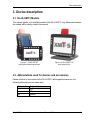
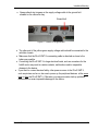
3. Device description
3.1. DLoG XMT 5 Models
This manual applies to all available models of the DLoG XMT 5. Any differences between
the models will be clearly noted in this manual.
Figure 3.1: DLoG XMT 5/7
(with optional mounting bracket)
Figure 3.2: DLoG XMT 5/10
(with optional foot)
3.2. Abbreviations used for devices and accessories
Please note that to save space on the DLoG XMT 5 and supplied accessories, the
following abbreviations have been used:
Abbreviation
+
Ign
DLoG XMT 5
Explanation
DC+
DCIgnition
User’s Manual V2.00
13
Device description
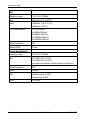
3.3. Device type plate
The device type plate on the DLoG XMT 5 contains the following information: :
DLoG XMT 5/7
or
DLoG XMT 5/10
Device type, 7“ or 10,4“ display
WVGA
or
SVGA
Display resolution
DC
Type of power supply, the following number indicate the
exact type of power supply with input voltage
24/48 V
2,5 A / 1,2 A
806 MHz
Input voltage of the DC power supply with nominal current
S/N ...
12 digit serial number composed of:
•
•
•
•
DLoG specific device code
Week of manufacture
Year of manufacture
Six digits for internal DLoG identification
Examples of device type plates:
Figure 3.3: Device type plate XMT 5/7
14
Figure 3.4: Device type plate XMT 5/10
User’s Manual V2.00
DLoG XMT 5
Device description
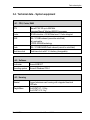
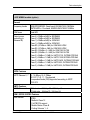
3.4. Technical data – System equipment
3.4.1. CPU, Cache, RAM
CPU
Marvell PXA 320 up to 806 MHz
integrated Marvell Wireless MMX2 Coprocessor
Cache
32 kB Instruction + 32 kB Data Level 1 Cache integriert
RAM
256 / 512 MB onboard (cannot be retrofitted)
fully cacheable
LPDDR-SDRAM technology
Flash
256 / 512 MB NAND-Flash onboard (cannot be retrofitted)
Real-time clock
Real-time clock with 3 V Li-battery (changeable)
3.4.2. Software
Bootloader
Microsoft EBOOT
Operating system
Microsoft Windows CE 6.0
3.4.3. Housing
Material
Rugged aluminum-cast housing with integrated heat sink
ESD safe
Weight/Mass
DLoG XMT 5/7: 2.2 kg
DLoG XMT 5/10: 3 kg
DLoG XMT 5
User’s Manual V2.00
15
Device description
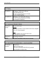
3.4.4. Display
DLoG XMT 5/7
LED Display 7“ WVGA, 800 x 480 pixel
Portrait and landscape use
500 cd/m² Luminance/brightness in Candela
Manuelle Helligkeitsregelung
DLoG XMT 5/10
LED-Display, 10,4’’ SVGA, 800 x 600 pixel
500 cd/m² Luminance/brightness in Candela
Manual brightness adjustment
3.4.5. Touch screen (Standard + Option)
Analog touch
controller
Resistive touch screen
Standard:
12 bit touch controller for 4-wire resistive touch screen, integrated
in PXA 320, drivers integrated
Option:
Sun light readable 5-wire resistive touch screen,
Hampshire A2 Touch Controller
Analog touch
interface
Internal plug-in connector
ESD Level 3 (according to EN 61000-4-2) protected
3.4.6. Audio interface for handset (Option – cannot be retrofitted)
Audio handset
connection
Microphone in
Audio out 2 W @ 8 Ohm
ESD Level 3 (according to EN 61000-4-2) protected
More information in chapter Audio
16
User’s Manual V2.00
DLoG XMT 5
Device description
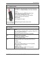
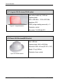
3.4.7. Integrated speaker
DLoG XMT 5/7: Integrated speaker on the side of the device
DLoG XMT 5/10: Integrated speaker on the rear of the device
Features:
Wolfson Microelectronics WM97115L Audio-Codec
AC97 controller integrated into PXA 320
Codec with separate 2 W@ 8 Ohm audio amplifier
Frequency response 400 to 20,000 Hz
IP65 protected
Driver integrated into image
Figure 3.5: Speaker on Additional information found in section Audio.
the side of DLoG XMT 5
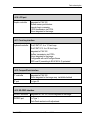
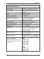
3.4.8. I/O ports
Serial port
COM1
max. 115.200 Baud (16550A/16750 compatible, 64 Byte FIFO)
EIA-232-E with Rx/Tx/RTS/CTS
ESD Level 3 (according to EN 61000-4-2) protected
LAN
IEEE 802.3/802.3u compatible
10 BASE-T and 100BASE-TX support
Full- and Half-Duplex support
USB
All USB ports ESD Level 3 (according to EN 61000-4-2)
protected
2 x USB 2.0 Host
USB-A Steckverbinder (USB 2.0 low / full / high speed)
mit abgesicherten 0,5 A pro Kanal
1 x USB 2.0 Client
USB-B plug-in connector (USB 2.0 full / high speed)
(for Microsoft ActiveSync only)*
DLoG XMT 5
User’s Manual V2.00
17
Device description
USB Service
1 x USB 2.0 Host, service port; placed under the antenna cap;
USB-A plug-in connector (USB 2.0 low / full / high speed) with
protected 0,5 A per channel.
More information in chapter 5.6 Service-USB under the antenna
cap
Figure 3.6: Service USB port
3.4.9. CAN 2.0 B (Option)
CAN 2.0 B
Cannot be retrofitted since the terminal must be equipped with a
CAN slot at the factory.
A suitable driver is integrated into the operating system. An API
description is available upon request. Please contact your
Advantech-DLoG salesperson if needed.
Technical description:
CAN V2.0B compatible, up to 1 Mbit/s
Galvanically isolated
ESD Level 3 (according to EN 61000-4-2) protected
ISO 11898-compatible transceiver module
18
User’s Manual V2.00
DLoG XMT 5
Device description
3.4.10. LCD port
Graphic controller
Integrated in PXA 320
Shared memory architecture
internal plug-in connector
LVDS transmission via FPGA
Driver integrated in the image
3.4.11. Front key interface
Keyboard controller DLoG XMT 5/7: 4 or 17 front keys
DLoG XMT 5/10: 4 or 25 front keys
Integrated in PXA 320
SerDes transmission via FPGA
Driver integrated in the image
Configurable with neXtConfig software
ESD Level 3 (according to EN 61000-4-2) protected
3.4.12. CompactFlash interface
CF controller
Integrated in PXA 320
Driver integrated in the image resp. installable belated
CF port
1 x type I/II
3.4.13. SD /SDIO interface
SD/SDIO controller
Integrated in PXA 320; Driver integrated in the image
SD/SDIO port
1 x Type 1
Push-Push mechanic with adjustment
DLoG XMT 5
User’s Manual V2.00
19
Device description
3.4.14. Power supply
The device model is displayed on the device type plate.
DC power pack
12/24 VDC
30 W internal
Type DC-x
12/24 VDC nominal (down to 5 V for 20 s max.)
Voltage range 9 to 36 VDC
Start voltage at least 9 VDC
Bridging of power failures of 5 ms at 12 VDC
Galvanically isolated
Maximum output: 30 W
Withstands bursts up to 2 kV
Nominal current of 4.2 A / 2.1 A
Connection to SELV circuit*) only
DC power pack
24/48 VDC
30 W internal
Type DC-y
24/48 VDC nominal (down to 10 V for 20 s max.)
Voltage range 18 to 60 VDC
Bridging of power failures of 5 ms at 24 VDC
Galvanically isolated
Maximum output: 30 W
Withstands bursts up to 2 kV
Nominal current of 2.5 A / 1.2 A
Connection to SELV circuit*) only
Maximum power
available for
peripheral devices
Power supply fuses
Power supply
Leistung
DC-x, DC-y
2 x 2.5 W for USB-Host
1 x 2 W for Audio Out
12 V / 1 A resp. 5 V / 1 A
@ 20 °C ambient temperature
Power supply
Fuse type
DC-x
DC-y
5 x 20 mm T 10 A / 250 V
5 x 20 mm T 4.0 A / 250 V
*) The
SELV circuit is a secondary circuit that is designed and protected so that its voltages will not
exceed a safe value both when operating correctly or if a single error occurs.
20
User’s Manual V2.00
DLoG XMT 5
Device description
3.4.15. Ambient conditions
Protection
IP 67 and IP 66 (IP 65 and IP 54 included)
Operating
temperature
In accordance with EN 60068-2-1/2
-30° to +50° C
Switch-on temperature >= -25 °C
Storage temperature In accordance with EN 60068-2-1/2
-35 to +65 °C
Relative humidity
In accordance with EN 60068-2-3
10% to 90% @ 40°C, non-condensating
Mechanical vibration Class 5M3 according to DIN EN 60721-3-5
and shockUS Highway Truck according to MIL-STD 810F
resistance
3.4.16. Test marks
See “Declaration of Confirmity“
DLoG XMT 5
User’s Manual V2.00
21
Device description
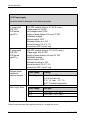
3.4.17. Integrated WLAN antenna (WLAN option)
Gain (without cable lost): 3 dBi max.
Frequency band:
2400 to 2485 MHz / 5150 to 5875 MHz
Impedance: 50 Ω
Figure 3.7: Integrated antenna
VSWR (voltage standing-wave ratio): < 2
Polarization: vertical
Max. power: 1 W (CW) @ 25°C
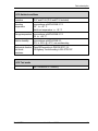
3.4.18. Remote WLAN antenna(WLAN option)
Gain: 4 dBi max.
Frequency band: 2400 to 5875 MHz
Dimensions: Ø 86 x 43 mm (Ø 3.39” x 1.69”)
Weight: 0,3 kg (0,66 lbs)
Polarization: linear, vertical
Figure 3.8: Remote antenna
22
User’s Manual V2.00
DLoG XMT 5
Device description
3.4.19. WLAN module (option)
System interface
16-bit CF Type I with 50-pin connection
Antenna interface
Two U.FL (Hirose) connectors for antenna
diversity
Chipset
Broadcom BCM4318E
Input power requirements
3.3 VDC +/- 5%
Typical power consumption (at
maximum transmit power setting)
Transmit: 400 mA (1320 mW)
Receive: 180 mA (594 mW)
Standby: 10 mA (33 mW)
Network standards
IEEE 802.11b, 802.11g, 802.11i
Network architecture types
Infrastructure and ad hoc
Frequency band
2.4 to 2.4897 GHz
Wireless media
Direct Sequence-Spread Spectrum (DSSS)
Orthogonal Frequency Divisional
Multiplexing (OFDM)
Media Access Protocol
Carrier sense multiple access with collision
avoidance (CSMA/CA)
Data Rates Supported
802.11b (DSSS): 1, 2, 5.5, 11 Mbps 802.11g
(OFDM): 6, 9, 12, 18, 24, 36, 48, 54 Mbps
Transmit Power Settings
DSSS:
19 dBm (80 mW)
17 dBm (50 mW)
15 dBm (30 mW)
10 dBm (10 mW)
0 dBm (1 mW)
Maximum transmit power will vary according
to individual country regulations. All values
nominal, +/-1.5dBm
OFDM:
15 dBm (30 mW)
10 dBm (10 mW)
0 dBm (1 mW)
DLoG XMT 5
User’s Manual V2.00
23
Device description
Typical Receiver Sensitivity
1 Mbps: -96 dBm
2 Mbps: -95 dBm
5.5 Mbps: -94 dBm
6 Mbps: -94 dBm
9 Mbps: -91 dBm
11 Mbps: -90 dBm
12 Mbps: -88 dBm
18 Mbps: -86 dBm
24 Mbps: -83 dBm
36 Mbps: -78 dBm
48 Mbps: -76 dBm
54 Mbps: -75 dBm
Delay Spread
1 Mbps: 600 ns
2 Mbps: 500 ns
5.5 Mbps: 400 ns
6 Mbps: 400 ns
9 Mbps: 400 ns
11 Mbps: 200 ns
12 Mbps: 350 ns
18 Mbps: 350 ns
24 Mbps: 250 ns
36 Mbps: 250 ns
48 Mbps: 150 ns
54 Mbps: 150 ns
24
User’s Manual V2.00
DLoG XMT 5
Device description
3.4.20. GPS (option)
General
L1 frequency (1575.42 MHz), C/A code (Standard
Positioning Service), 12-channel, continuous tracking
receiver
Update Rate
TSIP @ 1 Hz; NMEA @ 1 Hz; TAIP @ 1Hz
Accuracy
Horizontal: <5 meters (50%), <8 meters (90%)
Altitude: <10 meters (50%), <16 meters (90%)
Velocity: 0.06 m/sec.
PPS (static): ±50 nanoseconds
Acquisition
(Autonomous Operation in Standard Sensitivity Mode)
Reacquisition: <2 sec. (90%)
Hot Start: <10 sec. (50%), <13 sec. (90%)
Warm Start: <38 sec. (50%), <42 sec. (90%)
Cold Start: <50 sec. (50%), <84 sec. (90%)
(Cold Start requires no initialization, Warm Start implies
last position, time and almanac are saved
by backup power. Hot start implies ephemeris also saved.
Optional (COCOM) Limits
Altitude: 18,000 m
Velocity: 515 m/s
Either limit may be exceeded, but not both.
3.4.21. External magnetic Antenna for GPS, 5 m (Option)
Antenna
Frequency Range
1,575.42+/-1.023MHz
Gain
90°: 3.0dBi min.; 20°: -4.0dBi min.
(mounted on the 65mm x 65mm square ground plane)
Polarization
RHCP
Axial Ratio
90°: 4.0dB max.; 10°: 6.0dB max.
(mounted on the 65mm X 65mm square ground plane)
DLoG XMT 5
User’s Manual V2.00
25
Device description
LNA
Frequency range
1.575.42 ±1.023MHz
Gain
28 ±3 dB (-40°C to 85°C)
Noise
1.5dB max. (+25°C ± 5°C)
2.2dB max. (+85°C)
Out of band rejection
fo=1,575.42MHz
fo±20MHz 7dB min.
fo±30MHz 12dB min.
fo+/-50MHz 20dB min.
fo±100MHz 30dB min.
Output Impedance
50Ω
Output VSWR
2.0max.
Overall Specifications
Frequency range
1,575.42 ±1.023MHz
Gain
27 ± 3dBi (+25°C ± 5°C)
27 ± 4dBi (-40°C to 85°C)
(mounted on the 65mm x 65mm square ground plane)
Output Impedance
50Ω
VSWR
2.0MAX.
ESD
Antenna surface ± 15KV
Connector pin ± 8KV
MTBF
5.13E+6Hr.
26
User’s Manual V2.00
DLoG XMT 5
Device description
3.4.22. WWAN module (option)
General
Frequency bands
GSM/GPRS/EDGE: Quad band, 850/900/1800/1900MHz
UMTS/HSPA+: Five band, 800/850/AWS/1900/2100MHz
GSM class
Small MS
Output power
(according to
Release 99)
Class 4 (+33dBm ±2dB) for EGSM850
Class 4 (+33dBm ±2dB) for EGSM900
Class 1 (+30dBm ±2dB) for GSM1800
Class 1 (+30dBm ±2dB) for GSM1900
Class E2 (+27dBm ± 3dB) for GSM 850 8-PSK
Class E2 (+27dBm ± 3dB) for GSM 900 8-PSK
Class E2 (+26dBm +3 /-4dB) for GSM 1800 8-PSK
Class E2 (+26dBm +3 /-4dB) for GSM 1900 8-PSK
Class 3 (+24dBm +1/-3dB) for UMTS 2100, WCDMA FDD BdI
Class 3 (+24dBm +1/-3dB) for UMTS 1900,WCDMA FDD BdII
Class 3 (+24dBm +1/-3dB) for UMTS AWS, WCDMA FDD BdIV
Class 3 (+24dBm +1/-3dB) for UMTS 850, WCDMA FDD BdV
Class 3 (+24dBm +1/-3dB) for UMTS 800, WCDMA FDD BdVI
HSPA Features
3GPP Release 6, 7 DL 14.4Mbps, UL 5.7Mbps
UE CAT. [1-6], 11, 12 supported
Compressed mode (CM) supported according to 3GPP
TS25.212
UMTS Features
3GPP Release 4
PS data rate – 384 kbps DL / 384 kbps UL
CS data rate – 64 kbps DL / 64 kbps UL
GSM / GPRS / EGPRS Features
Data transfer
GPRS:
• Multislot Class 12
• Full PBCCH support
• Mobile Station Class B
• Coding Scheme 1 – 4
DLoG XMT 5
User’s Manual V2.00
27
Device description
EGPRS:
• Multislot Class 12
• EDGE E2 power class for 8 PSK
• Downlink coding schemes – CS 1-4, MCS 1-9
• Uplink coding schemes – CS 1-4, MCS 1-9
• SRB loopback and test mode B
• 8-bit, 11-bit RACH
• PBCCH support
• 1 phase/2 phase access procedures
• Link adaptation and IR
• NACC, extended UL TBF
• Mobile Station Class B
CSD:
• V.110, RLP, non-transparent
• 14.4kbps
• USSD
GPS Features
Protocol
NMEA
Modes
Standalone GPS
Assisted GPS
- Control plane - E911
- User plane - gpsOneXTRA™
General
Power saving modes
Power supply for active antenna
GPS tracking in parallel to 2G/3G diversity operation
Interfaces
UICC interface
28
Supported chip cards: UICC/SIM/USIM 3V, 1.8V
User’s Manual V2.00
DLoG XMT 5
Device description
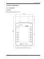
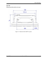
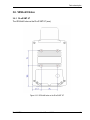
3.5. Device dimensions
3.5.1. DLoG XMT 5/7
Front view
Dimensions without add-ons (in mm):
Figure 3.9: Dimensions DLoG XMT 5/7 front view
DLoG XMT 5
User’s Manual V2.00
29
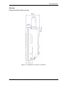
Device description
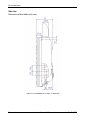
Side view
Dimensions without add-ons (in mm):
Figure 3.10: Dimensions DLoG XMT 5/7 side view
30
User’s Manual V2.00
DLoG XMT 5
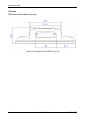
Device description
Top view
Dimensions without add-ons (in mm):
Figure 3.11: Dimensions DLoG XMT 5/7 top view
DLoG XMT 5
User’s Manual V2.00
31
Device description
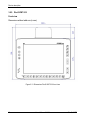
3.5.2. DLoG XMT 5/10
Front view
Dimensions without add-ons (in mm):
Figure 3.12: Dimensions DLoG XMT 5/10 front view
32
User’s Manual V2.00
DLoG XMT 5
Device description
Side view
Dimensions without add-ons (in mm):
Figure 3.13: Dimensions DLoG XMT 5/10 side view
DLoG XMT 5
User’s Manual V2.00
33
Device description
Top view
Dimensions without add-ons (in mm):
Figure 3.14: Dimensions DLoG XMT 5/10 top view
34
User’s Manual V2.00
DLoG XMT 5
Device description
3.6. VESA drill holes
3.6.1. DLoG XMT 5/7
The VESA drill holes on the DLoG XMT 5/7 (mm):
Figure 3.15: VESA drill holes on the DLoG XMT 5/7
DLoG XMT 5
User’s Manual V2.00
35
Device description
3.6.2. DLoG XMT 5/10
The VESA drill holes on the DLoG XMT 5/10 (mm):
Figure 3.16: VESA drill holes on the DLoG XMT 5/10
36
User’s Manual V2.00
DLoG XMT 5
Unpacking the device
4. Unpacking the device
4.1. Scope of delivery
The delivery includes at least the following:
• Ordered DLoG XMT 5 device
• Ordered assembly set
• Cable cover
• One connecting cable
Please verify the delivery contents immediately on receipt!
4.2. Packaging
The packaging material has been selected to optimally protect your device while
simultaneously offering the best possible ecological compatibility. We therefore kindly
request that you store the original packaging material or ensure it is used for another
suitable purpose such as transporting the unit or returning shipment.
Caution:
Property
damage
If you repack the device, please ensure that the cling wrap in the
cardboard frame is positioned towards the front of the device so that
it can provide the proper protection.
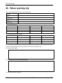
4.3. Returning your device
Due care was exercised when putting together the contents of your delivery and
dispatching your device. Nevertheless, if you still have cause for complaint, please
complete the form included in the appendix.
Should you need to return the device, please use the original packaging.
DLoG XMT 5
User’s Manual V2.00
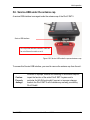
37
Initial operation
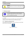
5. Initial operation
WARNING
Before operating the unit for the first time, carefully read the Safety
Guidelines.
5.1. Wireless networks
The following paragraph describes the software settings for the
current driver version at the time the manual was compiled. The
installation of subsequent driver versions will function similarly, but
some of the individual items may deviate.
5.1.1. WLAN
Depending on optional equipment and installation purpose of the DLoG XMT 5, the
settings/access data for a wireless network such as WLAN must be defined.
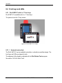
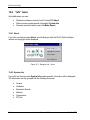
5.1.1.1. Summit Client Configuration (SCU)
Start the Summit Client Utility, referred to as SCU in the following, with a double finger
tap on the SCU icon on the desktop:
Figure 5.1: Summit Client Utility Icon
38
User’s Manual V2.00
DLoG XMT 5
Initial operation
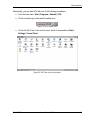
Alternatively, you can start SCU with one of the following procedures:
• From the start menu: Start | Programs | Summit | SCU.
• Or with a double tap on the specific taskbar icon:
Figure 5.2: SCU Taskbar Icon
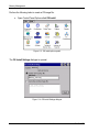
• Or with the Wi-Fi icon in the control panel, which is accessed from Start |
Settings | Control Panel:
Figure 5.3: Wi-Fi icon in the control panel
DLoG XMT 5
User’s Manual V2.00
39
Initial operation
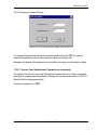
Password
Depending on the configuration, it may be necessary to enter a password.
Figure 5.4: SCU menu
• Click on the Admin Login button.
An entry field for the password appears.
• Enter the assigned password.
The standard password is: SUMMIT
Figure 5.5: SCU menu – password entry
40
User’s Manual V2.00
DLoG XMT 5
Initial operation
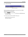
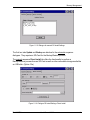
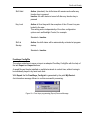
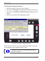
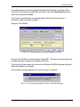
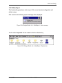
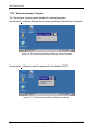
5.1.2. Summit Client Utility
Figure 5.6: SCU menu bar
Find more information on the WLAN settings in the online help of the menu Start |
Settings | Network Dial-Up Connections.
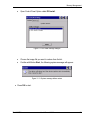
Important: to permanently save these settings:
• Enter the command saveregistry in the Windows menu Start | Run | open,
and confirm it with OK.
The TX Power settings for XMT5 with SUMMIT- WLAN card are:
Dual band antenna with diversity 50 mW
GGW Antenna: Maximum
DLoG XMT 5
User’s Manual V2.00
41
Initial operation
5.1.3. GPS
The following paragraph describes the software settings for the
current driver version at the time the manual was compiled. The
installation of subsequent driver versions will function similarly, but
some of the individual items may deviate.
Introduction
The DLoG XMT 5 can provide standardized data streams from the National Marine
Electronics Association (NMEA) by integrating an optional GPS receiver.
This data stream is provided to GPS applications via the GPS intermediate driver
(GPSID) in the operating system.
The GPSID is a software component of Microsoft that interacts between the GPS
hardware and the GPS application.
The GPSID driver offers the option of using the virtual COM port with multiple
applications.
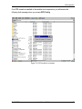
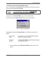
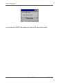
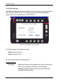
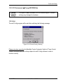
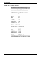
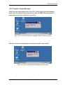
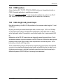
The NMEA data stream can be read via the COM9 virtual port.
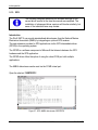
Open the shortcut “SERTEST9“.
Figure 5.7: GPS, NMEA data stream, SERTEST9
42
User’s Manual V2.00
DLoG XMT 5
Initial operation
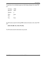
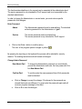
To open the port in an individual program, use the following settings for the virtual COM
port.
Port Name:
COM9
Baud rate:
38400
Data bits:
8
Parity:
None
Stop:
1
Flow:
None
The GPS receiver outputs the following NMEA sentence information via the virtual COM
port.
(GGA, GSV, RMC, GLL, GSA, VTG, ZDA)
The GPS receiver sends the data stream every second.
DLoG XMT 5
User’s Manual V2.00
43
Initial operation
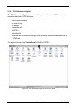
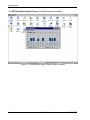
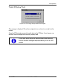
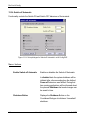
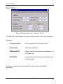
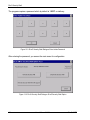
5.1.4. GPS Information Applet
The GPS Information Applet shows the following when the active GPS antenna is
connected and during GPS reception:
•
•
•
•
•
•
•
the current position
time of day
speed
satellite info
DOP’s
mode info
as well as the reception strength of the currently used and seen satellite in the
SNR tab.
The applet is found in the Control Panel of the DLoG XMT 5.
Figure 5.8: GPS Information Applet in the Control Panel
44
User’s Manual V2.00
DLoG XMT 5
Initial operation
The GPS Information Applet displays the current position.
Figure 5.9: GPS information display of current position
DLoG XMT 5
User’s Manual V2.00
45
Initial operation
The GPS Information Applet displays the signal strength of satellites.
Figure 5.10: GPS information display of signal strength of satellites
46
User’s Manual V2.00
DLoG XMT 5
Initial operation
5.1.5. GPS Receiver Configuration (GPS Config)
Support for the GPS module is a basic component of Standard
XMT5 DLoG CE6.00 Images. Perform the following steps only if the
GPS module was not a component of the supplied terminal.
• Open the folder \Windows.
Figure 5.11: \Windows file
DLoG XMT 5
User’s Manual V2.00
47
Initial operation
• Start the GPS Config program.
Figure 5.12: GPS Config XMT 5
The GPS config program provides a basic configuration for the GPS module.
• Click on the Default GPS Settings button.
The following message is displayed:
Figure 5.13: GPS Config: Settings successfully changed
The configuration sent is selected via a verification process. If the configuration is
successfully matched, the Success message appears and the GPS module
configuration is closed.
• Repeat this step or contact Support if the configuration fails and the message
“FAILED!” is displayed!
48
User’s Manual V2.00
DLoG XMT 5
Initial operation
"Default GPS Settings" Fault
Figure 5.14: GPS Config: Settings could not be changed
This message is displayed if the written configuration is sent back incorrectly from the
module.
Since the GPS module permanently sends data via the COM port, it can happen now
and then that the configuration cannot be properly read.
In this case, repeat the process described above and make sure
that the "Success" message is displayed before you use the GPS
module.
DLoG XMT 5
User’s Manual V2.00
49
Initial operation
Trouble-shooting GPS receiver
Problem:
No GPS reception or GPS information applet doesn't have the 2D/3D GPS fix, even after
a long wait time of approx. 10-15 minutes.
Solution:
Perform a “Hard Reset” with the "GPS Config" and discard the saved GPS data.
• Open the “\Windows”folder.
Figure 5.15: \Windows file
• Open the GPS config program.
• Click on the Advanced GPS Settings button.
50
User’s Manual V2.00
DLoG XMT 5
Initial operation
Figure 5.16: Advanced GPS Settings
• Click on the "Perform Hard Reset" button in the Advanced GPS Settings.
Figure 5.17: Perform HardReset
• Confirm the warning to perform the "Hard Reset”
Or:
Select "No“ to interrupt the process.
DLoG XMT 5
User’s Manual V2.00
51
Initial operation
Figure 5.18: HardReset performed successfully
• The "Hard Reset" was successfully performed.
• Press OK to confirm the message.
• End the application with Exit .
Figure 5.19: Exit GPS Settings
• You should now receive the 2D / 3D Fix in the GPS information applet within 5
minutes.
• If you still do not have GPS reception, please contact Support.
52
User’s Manual V2.00
DLoG XMT 5
Initial operation
If no GPS module is installed or the module is not responsive, you will receive the
following fault message when you access GPS Config:
Figure 5.20: GPS module is not present
DLoG XMT 5
User’s Manual V2.00
53
Initial operation
5.2. Protecting the TFT display from the memory effect
The TFT display of the DLoG XMT 5 has to be protected from the burning in of a
motionless image. An image that has remained motionless for too long can cause
irreversible damage to the display.
With TFT displays there no cathode rays burning in an afterimage as in old TV sets or
monitors, but TFT displays still have a “memory effect”. This is because with a still image
the liquid crystal molecules align themselves in a certain way and become inert if they
are not moved. Like burning in the effect is irreversible, but can be avoided by regularly
turning off the display or by using a screensaver with changing content.
5.3. Installing application software
You can install the required software, depending on the application, via WLAN or via the
USB client interface (ActiveSync).
5.4. Calibrate touch screen
The DLoG XMT 5 is precalibrated for delivery.
To fine tune, use the DLoG Admin Tools program, see section 14 DLoG Admin Tools.
54
User’s Manual V2.00
DLoG XMT 5
Initial operation
5.5. External Connectors
5.5.1. DLoG XMT 5/7
Figure 5.21: Connectors DLoG XMT 5/7
The connectors are assigned as follows:
Figure 5.22: Connector assignemet DLoG XMT 5/7
DLoG XMT 5
User’s Manual V2.00
55
Initial operation
5.5.2. DLoG XMT 5/10
Figure 5.23: Connectors DLoG XMT 5/10
The connectors are assigned as follows:
Figure 5.24: Connector assignemet DLoG XMT 5/10
56
User’s Manual V2.00
DLoG XMT 5
Initial operation
5.6. Service-USB under the antenna cap
A service USB interface is arranged under the antenna cap of the DLoG XMT 5.
Service USB interface
Do not pull the antenna connection cable too
far out of the unit or catch or cut it.
Figure 5.25: Service USB under the openend antenna cap
To access this Service USB interface, you need to remove the antenna cap from the unit.
Caution:
Property
damage
DLoG XMT 5
Incorrect or improper removal and fastening of the antenna cap can
impair the function of the entire DLoG XMT 5 system and in
particular the WLAN functionality! Incorrect or improper changes
made to the DLoG XMT 5 will invalidate any warranty provided by
DLoG GmbH.
User’s Manual V2.00
57
Initial operation
Unfasten antenna cap from unit and refasten it:
1. Unscrew the two screws from the antenna cap with an Allen key (size 3 mm).
1. Lift the antenna cap carefully to avoid pulling on the antenna connection cables
(max. 2 to 3 cm).
2. Keep hold of the antenna cap, making sure that no pulling tension is exerted on the
antenna connection cables.
3. The Service USB interface is now accessible.
CAUTION: One end of the antenna connection cables is attached to the antenna
cap, the other end to the internal WLAN unit of the DLoG XMT 5. The cables must
not be pulled out of the DLoG XMT 5 too far and become detached from the WLAN
unit! This might damage the WLAN unit or other components of the device.
4. Place the antenna cap back onto the DLoG XMT 5.
5. Take care not to trap the antenna connection cables when doing this.
The antenna cap seal must not be damaged; it must be seated correctly in the
groove.
6. Reinsert and tighten the two screws of the antenna cap (1 Nm torque).
58
User’s Manual V2.00
DLoG XMT 5
Initial operation
5.7. Power supply units 12/24 VDC and 24/48 VDC
Figure 5.26: External connectors DLoG XMT 5, DC 12/24 V, 30 W
Figure 5.27: External connectors DLoG XMT 5, DC 24/48 V, 30 W
DLoG XMT 5
User’s Manual V2.00
59
Initial operation
5.7.1. DC voltage supply connector
Version: Phoenix Combicon, 3pol.
Explanation:
Ignition on means that a control signal has to be routed to this connection (e.g., ignition
of a vehicle), that matches the supply voltage level and is able to supply at least 2 W.
The signal reference is DC-.
5.8. Audio (Option)
Read information in chapter:
19 Audio
60
User’s Manual V2.00
DLoG XMT 5
Initial operation
5.9. Connecting external devices
5.9.1. USB Connection
For connecting/removing USB devices, you must consider the maximum voltage that the
USB connection can supply.
Additionally, note whether the cable is provided with strain relief.
Otherwise no specific arrangements are required for the DLoG XMT 5.
5.9.2. COM Connections
Before connecting/removing devices on a COM interface, the current must be switched
off to the DLoG XMT 5.
Warning: Use only ferrite wire type 74271131 from Würth
Elektronik in order to comply with emissions norm
If you connect wires to the serial interface, please use a ferrite wire
from Würth Elektronik of type 74271131. You can purchase these
directly from Würth Elektronik or via DLoG. This step is necessary in
order to comply with the limit values in relation to EN 55022
("radiated emission").
DLoG XMT 5
User’s Manual V2.00
61
Initial operation
5.9.2.1. External devices, accessories
Caution:
Property
damage
DLoG XMT 5 must be disconnected from the power supply before
external accessories/devices are connected or disconnected to/from
the COM interface. Otherwise, you may damage the DLoG XMT 5
and the external accessories/devices.
Make sure that external peripheral devices with their own power
supply are switched on at the same time as the DLoG XMT 5 or
after you start the DLoG XMT 5. If this is not possible, please
ensure that the DLoG XMT 5 is adequately protected from power
leakage caused by an external device.
Powering down the DLoG XMT 5
• Power down the operating system (using the ignition input and/or the <Power>key.
• Disconnect the device from the supply voltage (pull off 3-pole Phoenix screw with
appropriate tools).
Powering up the DLoG XMT 5
After all devices are connected and DLoG XMT 5 is properly closed, then the device may
be switched on.
Please note that the connector for voltage supply and the connector in the COM socket
(if present) are screwed on.
Otherwise, you may damage the DLoG XMT 5.
Please observe also the mounting instructions delivered with your
DLoG XMT 5 device.
62
User’s Manual V2.00
DLoG XMT 5
Initial operation
5.10. Removing the protective film from the display
The front display of the DLoG XMT 5 is protected during transport by a transparent film.
This film should remain on the front display during assembly to avoid damage to the front
display surface.
1. Only remove the film once all of the assembly work has been completed.
2. Pull the foil slowly and carefully to avoid static charge. The terminal could be
damaged by high voltage.
DLoG XMT 5
User’s Manual V2.00
63
Accessories
6. Accessories
Caution:
Property
damage
Only use accessories that have been tested by DLoG GmbH and
approved for the DLoG XMT 5. You can get more information about
approved accessories from your DLoG sales representative.
6.1. Keyboard
On the DLoG XMT 5 any USB keyboard with USB-A connector can be connected.
6.1.1. SMALL keyboard
A mountable SMALL keyboard with protection class IP 65(German/English) is available.
Figure 6.1: SMALL keyboard
64
User’s Manual V2.00
DLoG XMT 5
Accessories
6.1.2. 24-key keypad
A 24-key keypad which can be mounted onto the device, with a protection class IP 65 is
available for the DLoG XMT 5
The 24-key keypad is only suitable for the assembly of devices with portrait display.
Figure 6.2: 24-key keypad DLoG XMT 5
6.2. Mouse
Any USB mouse with USB-A can be connected to the DLoG XMT 5. Only two mouse
keys are supported.
6.3. USB stick
You can connect a USB stick to the DLoG XMT 5 with a USB-A connector.
6.4. Scanner
You can connect scanners to either the USB port or the serial port. If connected to
COM1, the scanner can be powered through the port (optionally). Be sure to only use
scanners approved by DLoG GmbH.
6.5. WLAN cards
The WLAN card is connected via the CF card slot. In general, only drivers for WLAN
cards approved by DLoG GmbH can be integrated.
DLoG XMT 5
User’s Manual V2.00
65
Accessories
6.6. SD memory cards
SD memory cards can be inserted in the SD/SDIO slot.
Standard delivery: 1 GB; other sizes upon request.
Caution:
Property
damage
Be sure to only use SD memory cards that have been approved by
DLoG GmbH and that are released for the DLoG XMT 5.
Find out about released SD memory cards from your DLoG sales
representative.
6.7. Adapter cables
Various adapter cables are available, for example to change USB-B to USB-A format.
66
User’s Manual V2.00
DLoG XMT 5
Installation/Mounting
7. Installation/Mounting
WARNING
The unit could fall during transit or installation/mounting and cause
injury. Always ensure that there are two persons available when
installing or removing the device.
Before mounting the unit, carefully read the Basic safety guidelines.
The DLoG XMT 5 can be mounted in a variety of ways:
• It can be positioned horizontally on a desk or mounted on a steering wheel and
vehicle console.
• Wall mounts are also available for mounting the unit on machines and operating
panels.
• Roof mounting is also possible, for example under the vehicle roof.
Depending on the vibration resistance and pivoting demands, mounting brackets, clamp
foots or RAM mount elements can also be used to attach the device. Please contact
your DLoG sales office to find out more about the whole range of installation options on
offer.
7.1. Follow and retain the mounting instructions
Please follow the mounting instructions included with assembly kit when installing your
DLoG XMT 5. Please make sure that you retain the instructions.
DLoG XMT 5
User’s Manual V2.00
67
Installation/Mounting
7.2. Monting the device
7.2.1. Cooling through the supply of fresh air
The DLoG XMT 5 employs a passive cooling concept whereby the waste heat
generated inside the device is emitted from the surface of the housing. For this system to
function properly, sufficient fresh air circulation is required.
Never install the system in a closed environment where the cooling air is unable to
dissipate accumulated heat to the outside.
Caution:
Property
damage
68
If the DLoG XMT 5 does not have access to fresh cooling air, it may
result in overheating and severe damage to the unit. The maximum
permissible ambient temperature for the entire system needs to be
taken into account for the concrete application area.
User’s Manual V2.00
DLoG XMT 5
Installation/Mounting
7.3. Power supply
The DLoG XMT 5 series devices are available with an integrated, galvanically isolated
power supply for DC voltage.
If the device will be operated on AC, a converter is required. Please contact your DLoG
sales representative if needed.
The power from the power supply unit is designed for operating the device over the entire
range of operating temperatures. Additionally, expansion modules and/or external
devices can be operated.
7.3.1. Power supply 12/24 V and 24/48 V
The following integrated DC power supplies are available:
• DC power supply with 12/24 VDC input voltage, maximum output 30 W
• DC power supply with 24/48 VDC input voltage, maximum output 30 W
The DLoG XM 5 must only be connected to a SELV circuit. The
SELV circuit is a secondary circuit that is designed and protected so
that its voltages will not exceed a safe value both when operating
correctly or if a single error occurs.
Caution:
Property
damage
DLoG XMT 5
Ensure that there is a suitable disconnecting device such as a
power switch or circuit breaker in the power supply circuit. Ensure
that the disconnecting device isolates all supply voltage lines.
The DC+ connecting cable must be protected by a fuse (16 AT
max.).
The ignition connecting cable must be protected by a fuse of the
following type: 5 x 20 mm T 125 mA L / 250 V, for example, a
Wickmann 195-125 mA / 250 V.
User’s Manual V2.00
69
Installation/Mounting
7.3.2. Connecting cables
Use the connecting cables supplied by DLoG GmbH to connect the DLoG XMT 5 to the
power supply.
Make sure that the connecting cables are laid without kinks and are protected.
7.4. Vehicle applications (such as forklifts)
7.4.1. Electrical installation
Pay special attention to the various electrical potentials when installing the unit on a
vehicle (such as a forklift).
On the DLoG XMT 5, the logic ground and the shield ground are firmly linked.
The “logic ground” is the earth line (GND) for all of the internal electrical components,
such as the isplay and the CPU.
The cable shielding and the housing are connected to the “shield ground”.
Caution:
Property
damage
Pay attention to the following warnings!
• When connecting the DLoG XMT 5, please ensure that the on-board voltage of
the vehicle and the terminal input voltage match.
• The terminal input voltage can be found on the device nameplate and on the
sticker for the pin assignments.
• Some forklifts have a chassis that is connected to DC+. Therefore, the
DLoG XMT 5 chassis is also connected to DC+. However, if you use peripheral
devices that supply DC– to the DLoG XMT 5 via an interconnector (such as a
DC– serial port), this will cause a short circuit. This will inevitably lead to
malfunctions or even a total system failure.
• Please note that faults could occur in the power supply on forklifts with inverter
drive which are well over the tolerance potential of the DLoG XMT 5. This could
cause damage to the DLoG XMT 5. In such environments, the installation of a
line filter is required. Please contact your DLoG sales representative if needed.
70
User’s Manual V2.00
DLoG XMT 5
Installation/Mounting
• Always attach ring tongues on the supply voltage cable to the ground bolt
situated on the connector bay
Ground bolt
Figure 7.1: Position of the ground bolt
• The other end of the yellow-green supply voltage cable should be connected to the
vehicle’s chassis.
• Make sure that the DLoG XMT 5’s connecting cable is attached as close to the
battery as possible.
• Connecting the DLoG XMT 5 to large electrical loads, such as converters for the
forklift motor may result in random restarts, malfunctions and/or irreparable
damage to the device.
• If you want to connect devices fed by other power sources to the DLoG XMT 5,
such as printers and so on, be sure to power up the peripheral devices at the same
time or after the DLoG XMT 5. Otherwise, you may encounter start-up problems,
malfunctions or even irreparable damage to the device.
DLoG XMT 5
User’s Manual V2.00
71
Installation/Mounting
7.4.2. Position of the DLoG XMT 5 in the vehicle
In the vehicle, the driver's field of view must be kept free.
If a keyboard and scanner should be installed on the DLoG XMT 5, please plan sufficient
space.
No part of the DLoG XMT 5 system may project beyond the vehicle.
7.5. Cable cover (splash guard)
For safety reasons, the supplied cable cover for the external ports must be installed prior
to using the DLoG XMT 5.
7.5.1. Protection class
Please use the installation kit available as an option from DLoG to comply with the IP
protection rating. Please follow the installation instructions that are supplied with this
installation kit.
After completing assembly, the cables must be fixed to the strain relief rail with the
enclosed cable ties or strain relief clamps.
7.6. Minimum distance to WLAN antenna
CAUTION
In order to avoid exceeding the limits determined by the FCC for
exposure to radio waves, you (and other people in your vicinity)
should maintain a minimum distance of 20 cm from the antenna
integrated into the computer.
Please note this while mounting DLoG industrial computers with
WLAN antennas.
72
User’s Manual V2.00
DLoG XMT 5
Operation
8. Operation
8.1. Touch Screen
The DLoG XMT 5 is equipped with a resistive touch screen.
Caution:
Property
damage
If operated incorrectly, such as with sharp objects like screwdrivers,
the touch screen can be irreparably damaged.
Operation of the resistive touch screen is recommended with:
• clean, dry fingers
• clean, dry, soft gloves
• suitable touch stylus (plastic or wood, rounded tip, hardness 3H max.))
Resistive touch screens may not be operated with:
• ball-point pens or writing utensils,
• unsuitable touch styluses with a hardness greater than 3H (corresponds to pencil
hardness of 4H)
• tools of any kind (e.g. screwdrivers)
• sharp objects (knives, scalpels, etc).
DLoG XMT 5
User’s Manual V2.00
73
Operation
8.2. Front keys and LEDs
8.2.1. DLoG XMT 5/7 with 4 or 17 front keys
DLoG XMT 5/7 is available with 4 or 17 front keys.
The picture shows the 17-key-version:
Figure 8.1: DLoG XMT 5/7, 17 keys
8.2.1.1. Horizontal and vertical
The DLoG XMT 5/7 can be installed horizontally or vertically (convertible design). The
front keys and LEDs are aligned for both.
The alignment of the display is adjusted with the DLoG Admin Tools program.
See section 14 DLoG Admin Tools
74
User’s Manual V2.00
DLoG XMT 5
Operation
8.2.2. DLoG XMT 5/10 with 4 or 25 front keys
The DLoG XMT 5/10 is available with 4 or with 25 front keys.
The picture shows the 25-key-version:
Figure 8.2: DLoG XMT 5/10, 25 keys
8.2.3. Brightness control
Even after manually turning off the backlighting, the DLoG XMT 5 will continue to
respond to interaction via the keyboard, mouse or touch screen. This means that you can
continue to enter commands and data even if the display lighting is off.
DLoG XMT 5
User’s Manual V2.00
75
Operation
8.2.4. Function of front buttons and LED
Important when operating the <Power> button:
To turn the device on or off, press the <Power> button only briefly
(max. 1 sec.) and immediately release it.
If you hold the <Power> button down for longer or press it again the
on/off process can be delayed.
Turning the DLoG XMT 5 on and off. This button has been
preconfigured by DLoG GmbH by default:
DLoG XMT 5 with
automatic switch-off:
<Power> key is not used for powering up the
unit.
DLoG XMT 5 without
automatic switch-off:
<Power> key is used to power up the unit. If
the button is pressed while the unit is
operating, this results in a HARD shutdown.
This may lead to data loss!
Manual brightness control/backlighting:
<+> button for manual brightness control (increase
brightness)
<-> button for manual brightness control (reduce brightness)
Turning the backlighting ON/OFF
76
User’s Manual V2.00
DLoG XMT 5
Operation
Temp (red) LED for displaying high/low temperatures in
the device.
Temp too low: LED blinks -> 0.5 sec ON, 0.75 sec OFF,
repeats 5 times, then 2 sec pause and repeat…
Temp too high: LED blinks 0.25 sec ON, 0.375 sec OFF,
repeats 4 times, then 2 sec pause and repeat…
Temperature sensor defective: LED blinks 0.25 sec ON,
0.25 sec OFF, repeats 10 times, then 1.25 sec pause and
repeat…
Activity LED (yellow) lights when there is activity on the I/O
interface.
Power LED (green) to display an existing supply voltage; this
LED is constantly lit as soon as the CPU is started.
DLoG XMT 5
User’s Manual V2.00
77
Operation
Scroll keys:
Page up
Page down
Home
End
Special keys <S1> and <S2>;
Define this keys with the Next Config Software.
See section 12 DLoG neXt Config
<Esc>-key
<Enter>-key
78
User’s Manual V2.00
DLoG XMT 5
Operation
LED: indicates the status of the <Shift> key
<Shift> key
<F>-keys are double-allocated:
• Digit 0 to 9, point and backspace
• If the <Shift> key is pressed:
Function keys F1 to F12
Define the keys with the Next Config Software.
See section 12 DLoG neXt Config
DLoG XMT 5
User’s Manual V2.00
79
Bootloader
9. Bootloader
The bootloader of the DLoG XMT5-Series initializes, configures and tests the Hardware
about current configuration settings. Afterwards the operating system is loaded.
The DLoG XMT 5’s Windows CE 6.0 Bootloader is based on the EBOOT from Microsoft.
10. Operating System
The terminals of the DLoG XMT5-Series are offered with the Windows CE 6.0 operating
system.
The ordere operating systems is factory pre-installed. It is loaded after finished EBOOT
initialization.
System specific device drivers such for (display, sound, network, touch) are pre-installed
as well.
The operating system is programmed in an Onboard Flash-Memory. Free memory that is
not in use by the operating system can hold user specific data.
Memory expansion is also available via USB. An SD card with 1 GB memory is included
and installed in the standard scope of supply (other sizes available upon request).
80
User’s Manual V2.00
DLoG XMT 5
Memory Management
11. Memory Management
The DLoG XMT 5 Series contains two installed Windows CE operating systems on two
separated Flash-Memory areas.
11.1. NOR-Flash Memory
The NOR-Flash (32 MByte) contains next to the EBOOT and it’s configuration the
BootSplashScreen and the “GenericBootMode” CE Image.
NOR – FLASH
E
E
B
O
O
T
B
O
NK.bin (“Generic BootMode image” )
O
T
C
(SIMAGE.zip)
F
G
0 MB
1 MB
32MB
Figure 11.1: NOR-Flash Memory
The NOR-Flash area and its content can not be changed during
normal operation. Perform updates only after clearance with the
DLoG Service and according to the DLoG Service’s instructions.
The „Generic BootMode“ CE Image will be loaded/run during a Backup/Restore process
of the NAND user based Windows CE image.
DLoG XMT 5
User’s Manual V2.00
81
Memory Management
11.2. NAND-Flash Memory
The NAND-Flash contains the user Windows CE image file, additional installed
programs, drivers and settings.
NAND – FLASH
Visible Partition mounted as Root
Hidden Partition
Storage Area, Registry,
Programs
0 MB
(NAND based
Image file .IMG)
≈ 194 MB
244 MB
(depends on NK.bin size)
Figure 11.2: NAND-Flash Memory
The OS Install functionality for Backup/Restore purpose saves the
complete content of the NAND-Flash area.
82
User’s Manual V2.00
DLoG XMT 5
Memory Management
11.3. CE Image (Backup/Restore)
The function OS Install offers the functionality to perform a Backup/Restore process of
an CE Image file (NAND Flash area)
There a two different ways to perform a Backup/Restore process: automatic or manual.
In most cases the automatic sequence is recommended to use, described in the next
part.
An SD-Card (delivery standard: 1 GByte) is required to perform the
automatic Backup/Restore process of an CE image file.
11.3.1. How to create an Image Backup file
During the process the following parts will be saved in an image file:
•
•
•
The Windows CE operating system
Additional installed programs and drivers
Changed System settings and the Registry
Requirements:
An SD-Card must be present.
The folder SDCard\Install has to be exist.
DLoG XMT 5
User’s Manual V2.00
83
Memory Management
Perform the following tasks to create a CE image file:
• Open Control Panel Option called OS Install:
Figure 11.3: OS Install option symbol
The OS Install Settings dialogue is opened:
Figure 11.4: OS Install Settings dialogue
84
User’s Manual V2.00
DLoG XMT 5
Memory Management
• Activate option create new backup file and enter a valid filename for the image
file. Be sure to enter the file extension “.img”!
• Alternatively, an already existing image file can be overwritten by choosing the
option overwrite existing image file.
• Confirm with Button Start, the following system message will appear:
Figure 11.5: System message before backup
• Press Button OK to proceed or button X to abort process.
Afterwards, the terminal will be started automatically, the NOR based Generic BootMode
CEImage will be loaded and the NAND user CE image will be saved.
Figure 11.6: Reboot after loading/saving the .IMG file
DLoG XMT 5
User’s Manual V2.00
85
Memory Management
An automatic terminal reboot will be performed, after the image backup process was
finished. The Backup file was saved successfully on the SD-Card:
Figure 11.7: Backup file successfully saved on the SD-Card
11.3.2. How to restore an Image Backup file
The Restore contains the following parts:
•
•
•
The Windows CE operating system
Additional installed programs, drivers
Changed System settings and the Registry
Requirement:
An SD-Card must be present.
The folder SDCard\Install has to be exist.
Perform the following tasks to restore a CE image file:
Figure 11.8: OS Install option symbol
86
User’s Manual V2.00
DLoG XMT 5
Memory Management
•
Open Control Panel Option called OS Install:
Figure 11.9: OS Install Settings dialogue
•
•
Choose the image file you want to restore from the list.
Confirm with Button Start, the following system message will appear:
Figure 11.10: System message before restore
• Press OK to start.
DLoG XMT 5
User’s Manual V2.00
87
Memory Management
In case, that the selected image file is not valid for this terminal type a system message
will be shown:
Figure 11.11: Error message: Image file is not compatible
•
•
•
Close the error message dialogue with Button OK.
Select a compatible image file.
Press button OK to start.
Afterwards, the terminal will be started automatically, the NOR based Generic BootMode
CEImage will be loaded and the NAND user CE image will be restored.
Figure 11.12: Automatic terminal reboot
An automatic terminal reboot will be performed, after the image restore process was
finished.
88
User’s Manual V2.00
DLoG XMT 5
Memory Management
11.3.3. Manual interaction (Generic-Boot-Mode) image
Next to the already described automatic Backup create/restore process there is also the
way to perform the required steps manually.
Caution:
Property
damage
The following description was designed for Administrators with
experienced knowledge using the Windows CE system.
As preparation, the Generic BootMode image must be started manually.
The Control Panel Option Reset OS Install offers the required functionality.
Figure 11.13: Reset OS Install dialogue
By changing the status (Button Change Status), the next Boot-up command can be
defined:
•
Normal System
startup
At next Boot-up, the user specific NAND-Flash based
Windows CE image will be loaded.
OS Install is
activated
The Generic-Boot-Mode image will be loaded to perform
a Backup/Restore process.
After changing the value to OS Install is activated, perform a reboot of the
system.
DLoG XMT 5
User’s Manual V2.00
89
Memory Management
The following message will appear after the startup:
Figure 11.14: Error message/OS Install
•
Confirm this message with No.
The OS Install Settings dialogue for manual interaction will be opened.
90
User’s Manual V2.00
DLoG XMT 5
Memory Management
Figure 11.15: Dialogue for manual OS Install Settings
The first two tabs Update and Backup are identical to the automatic sequence
dialogues. They require an SD-Card for the Backup/Restore process.
The manual sequence Direct Install tab offers the functionality to perform a
Backup/Restore process from an SD-Card as well as other removable storage media like
an USB stick. (Option: File)
Figure 11.16: Dialogue OS Install Settings: Direct Install
DLoG XMT 5
User’s Manual V2.00
91
Memory Management
To create/restore an image file just change the corresponding dialogue controls called
Update/Backup.
After a successful finished Update/Backup process and the
following reboot, the NAND based user Windows CE image starts
again atomatically. You have to set the Reset OS Install
ControlPanel Applet each time the Generic-BootMode image
should be loaded instead of the NAND based user CE image.
In case that no Backup/Update process was performed, a manual interaction must be
done to reset the OS Install Flag (Control Panel Applet). Otherwise, the GenericBootMode CE image starts every time the terminal is switched on.
Note the following description for further information.
11.4. Generic-BootMode CE Image operation
The NOR-Flash based „Generic-BootMode“ CE image main purpose is to maintenance
the system and to restore NAND based user Windows CE image files.
The DLoG Security Shell option is always enabled while executing
the Generic-BootMode image. The NAND specified password can
not be used here. The system access is only possible with default
password (4653).
Changes can not be saved and will be flushed after a system
reboot.
Check chapter 13 DLoG Security Shell for further information
regarding the DLoG SecurityShell option.
92
User’s Manual V2.00
DLoG XMT 5
Memory Management
11.4.1. Reset of the OSInstall Flag
As already described in former parts that explained the Backup/Restore process of an
Windows CE .IMG file, it can be necessary to reset the OSInstall Flag manually to
restore the normal Windows CE startup process:
Perform the following steps in order:
•
•
Desktop right click option Admin Tools – Enter Admin Mode
Enter default password 4653
Figure 11.17: DLoG Security Shell dialogue
•
•
Execute option Deactivate Security Shell and confirm upcoming message
with OK.
Open ControlPanel Option Reset OS Install and change by button Change
Status the next Boot-up command to Normal System startup.
DLoG XMT 5
User’s Manual V2.00
93
Memory Management
Figure 11.18: OS Install Status dialogue
At next startup the NAND-Flash based user Windows CE image will be loaded.
94
User’s Manual V2.00
DLoG XMT 5
DLoG neXt Config
12. DLoG neXt Config
12.1. Overview
12.1.1. Display brightness, automatic switch-off etc. configuration
Important settings for the DLoG XMT 5 series with Windows CE, e.g. for display
brightness, automatic switch-off and possibly front key configuration are done with the
neXt Config.EXE software.
Please note that these settings are only possible if the respective
option has been purchased.
12.1.2. Dialogue in neXt Config.EXE in portrait or landscape format
Depending on the display setting selected on the DLoG XMT 5 the neXt Config.EXE
dialogue will be displayed in landscape or portrait format.
12.1.3. Saving neXt Config.EXE settings
To save neXt Config.EXE settings, it is sufficient to quit the corresponding program
dialogue with OK. It is not necessary to use the “saveregistry“ command.
12.1.4. Starting neXt Config.EXE
Due to special interaction between the hardware and software the neXt Config.EXEsoftware can only be started once simultaneously (only one instance). A second start will
fail.
Firstly ensure that no program symbol is displayed in the taskbar. If you can see the
symbol the program is already running.
Figure 12.1: Symbol for started neXt Config.EXE in the taskbar
DLoG XMT 5
User’s Manual V2.00
95
DLoG neXt Config
12.1.4.1. Automatic Start
As a rule the DLoG XMT 5 device is configured from the factory so that the neXt Configsoftware starts automatically when the computer is started up.
Programs which start automatically are under Windows | Startup.
12.1.4.2. Manual Start
Manual start is necessary if the neXt Config program was closed by clicking on the menu
item Advanced | Exit.
If this menu item is deactivated you might possibly not be authorized to end the program.
You must be in Administrator mode in order to be able to close the program. You can
find more detailed information on this under the menu item Advanced | Change Mode.
By clicking on the cross in the top right-hand corner the program won’t be closed, the
software window is merely minimized.
By clicking on the program symbol in the taskbar the appropriate software window will be
displayed again.
Requirements for manual start:
•
•
The hidden data and folders
My Device -> Windows -> StartUp must be displayed.
And the protected operating system files must be displayed.
If the files are not displayed on your DLoG XMT 5 device:
•
•
•
•
•
96
Click on the menu item View and then on Options.
Deactivate the small control boxes. Do not show hidden files and folders
and Hide protected operating system files.
Then click on OK. Now the Windows file will be displayed.
Now go to the StartUp file.
You can start the neXt Config.EXE by double clicking on the program symbol.
User’s Manual V2.00
DLoG XMT 5
DLoG neXt Config
12.1.4.3. Start Screen
The basic initialization will run by starting the neXt Config-software.
Until activation of the software the following tasks will be performed:
•
•
•
Establishing communication with the Environment Controller
Request setting information from Environment Controller. (Switch-off automatic
settings, etc.)
Loading Setup
After successful start-up the program symbol will be displayed in the taskbar.
If a test fails the software does not start and an appropriate error message is given. In
this case contact DLoG support.
If you try to start the software a second time an error will occur and the second attempt
will be aborted.
12.1.5. neXt Config Menu Bar
If any menu items in the menu bar are deactivated it is possible that you do not possess
the necessary rights for changing these settings. You can find more detailed information
on this in the menu item Advanced | Change Mode.
DLoG XMT 5
User’s Manual V2.00
97
DLoG neXt Config
12.2. “Options” menu
In the menu Options the following functions are available:
•
•
•
Backlight Control
Set Front Keys
Switch-off Automatic
12.2.1. Backlight Control
Used for configuring the display brightness. All front keys up to the <Power> key,
independently of the setting selected, are inactive with open dialogue and cannot be
used. The keys cannot be used again until the configuration screen is closed.
Figure 12.2: Set-up dialogue for display brightness
Backlight Key Setup (key configuration for backlight):
Backlight Key
98
Activates or deactivates the backlight key on the front of
the device.
User’s Manual V2.00
DLoG XMT 5
DLoG neXt Config
Brightness Control (Display brightness):
Only one mechanism can be selected for brightness control
+/- Front keys
Activates or deactivates the + and – keys on the
front of the device.
Fixed
Sets a fixed brightness for the display. Use the
slide control to adjust to the brightness required.
(The saved value will be automatically set on
system restart.)
Restore Default
Sets the standard values: (Backlight key Enabled)
(Brightness control +\- Front keys)
Save
Saves and activates the settings made. The
settings can also be saved by clicking on OK.
However, with this button you can test various
settings without having to close the dialogue
window first. (Provided that the Brightness Control
is set to the Fixed value)
In case the Front Key based brightness control functionality works not as expected, a
“fallback” scenario was integrated.
By press and hold the Backlight Key for around 10 seconds the actual brightness value
will be set to 100% (highest possible brightness).
This function works independent of the current Brightness Control
configuration settings (active / inactive).
DLoG XMT 5
User’s Manual V2.00
99
DLoG neXt Config
12.2.2. Set Front Keys
With Set Front Keys you can allocate specific button commands or program requests to
the front keys on the DLoG XMT 5. On starting the function an interactive graphic
appears with all the available keys of the DLoG XMT 5.
Figure 12.3: Dialogue for front key settings
The following apply for the description below:
Active means: checks set.
Inactive: checks not set.
The main window offers the following options:
Optional Settings
Key Repeat
100
Active: the function will be repeated if the front key is held down
after a short start delay, until the key is released again.
Inactive (standard): the function will only be performed once
even with the key held down.
User’s Manual V2.00
DLoG XMT 5
DLoG neXt Config
Shift Hold
Active: (standard): the shift status still remains active after any
function key is pressed.
Inactive: the shift status is turned off after any function key is
pressed
Key Lock
Active: all front keys with the exception of the <Power>-key are
locked to the user.
This setting works independently of the other configuration
options such as Backlight Control, for example.
Standard = Inactive
Shift at
Startup:
Active: the shift status will be automatically activated at program
startup.
Standard = Inactive
Frontkeys ConfigFile
The option exists here to save or import an adapted FrontKey ConfigFile with the help of
the two Export and Import buttons.
A saved file can thus be installed on multiple terminals in a short time, without having to
be individually keyed in by hand each time.
With Export the file FrontKeys_Config.txt is generated by the path \My Device\.
An information message follows to confirm successful processing:
Figure 12.4: Front keys programming (Export) Success Message
DLoG XMT 5
User’s Manual V2.00
101
DLoG neXt Config
Sample view: (FrontKeys_Config.txt)
Figure 12.5: Front keys programming (Export) ConfigFile view
The example shown above corresponds to the standard configuration of 17 front keys.
ATTENTION:
Caution:
Property
damage
102
The file is not intended for external processing. Manual changes
which are not supported by neXt Config, can lead to program errors
in the front key configuration and so to runtime errors during
execution! Creation or amendment of the key arrangement may only
be done in neXt Config in order to exclude operating errors!
User’s Manual V2.00
DLoG XMT 5
DLoG neXt Config
With Import the file \MyDevice\FrontKeys_Config.tx is sought. After successful import
the following system message is issued:
Figure 12.6: Front key programming (import) Success Message
If the file is not found or has already been opened by a different program such as
“WordPad” for example, the following message will be displayed with the import attempt:
Figure 12.7: Front key programming (Import - File access failed) Message
DLoG XMT 5
User’s Manual V2.00
103
DLoG neXt Config
12.2.3. Allocating Front Keys with Functions
•
Type into the graphic on a front key in order to configure it.
•
When typing on the Backlight keys the Backlight setting dialogue will be opened.
•
When typing on the PowerKey the Switch-off Automatic setting dialogue will be
opened.
•
With all other function keys the following dialogue is opened
Figure 12.8: Set-up dialogue for front key programming
All front keys up to the <Power> key cannot be used with open dialogue. The keys can
only be used again once the configuration screen is closed.
The function of the <Shift> key is predetermined and cannot be
amended or configured.
104
User’s Manual V2.00
DLoG XMT 5
DLoG neXt Config
In principle three different modes are provided for key configuration:
Text
For typing a freely configurable character sequence.
Program
To start a predefined program (including retrieval parameters,
if necessary)
VK Codes
Used for menu-controlled selection of key commands. In
addition to this you also have the option of programming your
own key combination based on VK codes.
A more precise description of the individual options follows after the description of the
general buttons:
The general buttons:
Shift state
Activate or deactivate <Shift> key.
Restore
default
To reset the original “standard” configuration of the respective
key. Can be used in standard and also “shift mode”.
Save
Save the configuration made.
Cancel
Reject changes and close dialogue.
DLoG XMT 5
User’s Manual V2.00
105
DLoG neXt Config
“Text” setting mode
Figure 12.9: Set-up dialogue for front key programming (Option: “Text”)
In Text Mode a free input text line can be programmed which is displayed accordingly on
key confirmation.
Due to a known function restriction of the .NET compact framework environment, it is not
possible to include the following special characters within the text: % ^ ( ) + { } ~ &
In this case the special character must be appropriately programmed using the VK
Codes option.
106
User’s Manual V2.00
DLoG XMT 5
DLoG neXt Config
“Program” setting mode
Figure 12.10: Set-up dialogue for front key programming (Option: “Program”)
The Program function can be used when starting a program (including retrieval
parameters).
For this purpose use the <Browse> button to select the program to be started.
Where retrieval parameters are used these must be denoted by using a space after the
program name.
Buttons:
Browse
For selection of the program to be started.
Test
For a function test of the selected program.
DLoG XMT 5
User’s Manual V2.00
107
DLoG neXt Config
“VK Codes” Setting Mode
Figure 12.11: Set-up dialogue for front key programming (Option: “VK Codes”)
Here standard key combinations such as (“Ctrl+Alt+Del”) can be configured with the help
of the selection menu provided for this
However, self-defined “key sequences” can also be hidden behind these.
Menus / buttons:
108
Menu: Control-Keys
The following standard Control Keys are supported:
(Shift, Ctrl, Alt, AltGr, WinButton, AppButton, (Ctrl+Alt),
(Ctrl+Shift))
Menu: Function-Keys
Here all standard Function-Keys can be selected. Above
all this includes the standard keys (0-9, A-Z) as well as
the F keys. Special keys (VK_OEM_X) can also be
selected but independently of the keyboard layout. The
“EN-US” keyboard layout is supported by default.
Check Box:
Key Sequence
This is used to change between the key sequences
input manually and from the menu.
User’s Manual V2.00
DLoG XMT 5
DLoG neXt Config
The action keys can also be programmed manually with Windows Virtual Key Codes.
The Virtual Key Codes are entered after activation of the option Key Sequence into the
editor line and saved with Save.
Up to three key combinations can be programmed. With two or three keys the +
character is used as a logical separator.
Example: (Ctrl+Alt+Del)
Figure 12.12: Set-up dialogue for front key programming VK Code
Entry for (Ctrl+Alt+Del) is as shown above “A2+A4+2E”. The Plus sign must be input as a
so-called “separator” between the individual VK Codes.
The Virtual Key Code names can be found on the Microsoft MSDN homepage (Microsoft
Developer Network), for example.
An information message appears upon incorrect entry or command:
Figure 12.13: Front key programming VK Codes - Invalid Input Message
DLoG XMT 5
User’s Manual V2.00
109
DLoG neXt Config
12.2.4. Switch-off Automatic
Functionality controls the Switch-ON and Switch-OFF behaviour of the terminal.
Figure 12.14: Set-up dialogue for Switch-off Automatic in neXt Config.EXE
Menus / buttons:
Enable Switch-off Automatic
Enables or disables the Switch-off Automatic.
In disabled state the system shutdown will be
initiated after a few seconds when the defined
Power-off behaviour was fulfilled. During that
time running applications will be informed about
the planned Shutdown that made changes can
be saved in time.
Shutdown Button
110
Displays the Shutdown Button on the
Countdown-Dialogue to initiate an “immediate”
shutdown.
User’s Manual V2.00
DLoG XMT 5
DLoG neXt Config
Delay time
Time between switching off ignition signal and
starting shutdown. If the Ignition signal is
restarted, the system will return to standard
operation.
The Delay time is only valid in combination with
the Ignition. In case the Powerkey is used to
switch off the terminal the delay time will be
skipped.
Switch-off time
Time until the terminal will be switched off. This
time interval starts directly at ending of the Delay
Time and can not be aborted. Short until the
“Switch off” timer reaches the end running
applications will be informed about the planned
“Shutdown” that made changes can be saved in
time.
Restore default
Restores the default PowerOn \ PowerOff settings
to the following values:
• Enable Switch-off Automatic
• Enable Shutdown Button
• Delay / Switch-off time Æ 5 sec.
• PowerOn \ PowerOff Æ PowerKey
Save
DLoG XMT 5
The actual configuration will be saved.
User’s Manual V2.00
111
DLoG neXt Config
12.2.4.1. System Messages (Shut-Down)
During Shutdown preparation two BROADCAST system messages will be send to inform
running applications that the actual session is about to end.
Right after finished Delay Time
WM_QUERYENDSESSION
Short time before Switch-off Time ends
WM_ENDSESSION
These standard Windows CE messages can be integrated in own software application
projects to save current progress in time before a system shutdown is initiated.
12.2.4.2. Power on
Proceed carefully with these settings! These definitions determine which action starts the
DLoG XMT5-terminal.
Caution:
Property
damage
112
Do NOT select Ignition if an ignition cable has not been connected.
If you select Ignition and an ignition cable has not been connected,
the DLoG XMT5-terminal will no longer start.
Do NOT select Power key + Ignition if an ignition cable has not
been connected. If you select this setting and an ignition cable has
not been connected, the DLoG XMT5-terminal will no longer start.
Always On
The DLoG XMT5-terminal switches on as soon as it is
supplied with power. It is not necessary to press the
<Power> key or start the ignition.
Power key
The computer can be switched on with the <Power>
key.
User’s Manual V2.00
DLoG XMT 5
DLoG neXt Config
Important when operating the <Power> button:
To turn the device on or off, press the <Power> button only briefly
(max. 1 sec.) and immediately release it.
If you hold the <Power> button down for longer or press it again the
on/off process can be delayed.
Ignition
The computer switches on automitcally when the
ignition is started. It cannot be switched on with the
<Power> key.
Power key or Ignition
The computer can be switched on with the ignition
signal or the <Power> key.
Power key + Ignition
The computer can be switched on with the <Power>
key if the ignition is on. It cannot be switched on with
the <Power> key alone.
12.2.4.3. Power off
Proceed carefully with these settings! These definitions determine which action switches
off the DLoG XMT5-terminal.
Caution:
Property
damage
DLoG XMT 5
Do NOT select Ignition if an ignition cable has not been connected.
If you select Ignition and an ignition cable has not been connected,
the Switch-off behaviour can not be initiated and the terminal will not
be switched off.
Do NOT select Power key + Ignition if an ignition cable has not
been connected. If you select this setting and an ignition cable has
not been connected, the Switch-off behaviour can not be initiated
and the terminal will not be switched off.
User’s Manual V2.00
113
DLoG neXt Config
Never
The DLoG XMT5 switches off as soon as it is no
longer supplied with power.
Power Key
The computer is shut down or switched off with the
<Power> key.
Important when operating the <Power> button:
To turn the device on or off, press the <Power> button only briefly
(max. 1 sec.) and immediately release it.
If you hold the <Power> button down for longer or press it again the
on/off process can be delayed.
114
Ignition
Switching off the ignition activates the automatic
switch off function. The terminal will switch off after
defined “Delay time”.
Power key or Ignition
The computer can be switched off with the ignition
signal or the <Power> key.
Power key + Ignition
Automatic switch off is activated when the ignition is
switched off. The Shutdown Button can be used to
skip the defined Switch-off time and initate the
“direct” Shutdown.
User’s Manual V2.00
DLoG XMT 5
DLoG neXt Config
12.3. “Advanced” menu
In the Advanced menu the following functions are available:
•
•
•
•
Change Mode
PIC Environment Æ Change EEPROM Data
Production Set
Exit
12.3.1. Change Mode
In the Change Mode menu item the execution mode of the neXt Config programs can be
amended.
There are three different levels of authorization:
•
•
•
User
Admin (administrator)
and Service
Dialogue view:
Figure 12.15: Dialogue: Advanced – Change Mode
The program is started at the User level by default. This can be seen from the green
program symbol on the taskbar.
DLoG XMT 5
User’s Manual V2.00
115
DLoG neXt Config
The functions described here in the manual can be amended at the administrator level.
The service password is only intended for DLoG support and is not accessible by the
standard administrator.
In order to change the Administrator or service levels, you must enter a specific
password in this dialogue:
Enter Password
•
Admin
The Administrator password must be entered here. The standard
ex-factory password for the Administrator is “gold”.
Service
The service password must be entered here.
The service password is only intended for DLoG support.
Click on the<Enter> button to confirm (entry).
The color of the program symbol changes to yellow.
By pressing the input key on the keyboard the process will be aborted for security
reasons. The existing execution mode will remain unchanged.
Change Admin Password
•
•
116
New Admin Pwd
To change the Administrator password you must identify
yourself as Administrator and enter the new password in the
box New Admin Pwd.
Confirm Pwd
To confirm enter the same password here. Both passwords
must be identical.
Click on Change to accept the change. If the boxes for the password are
cleared their input was different. You must enter the password again and will
receive a program message to this effect.
Click on X to close the dialogue.
User’s Manual V2.00
DLoG XMT 5
DLoG neXt Config
12.3.2. PIC Environment Æ Change EEPROM Data
Caution:
Property
damage
This option is ONLY available to DLoG technical support. Incorrect
settings may damage the hardware.
12.3.3. Exit
The neXt Config program will be exit after confirming the following message:
Figure 12.16: Exit neXt Config - Warning
Please note when canceling: the Backlight Control, Automatic Switch-off, Temp Control,
XReboot command and the front keys require the neXt Config software in order to
function correctly.
DLoG XMT 5
User’s Manual V2.00
117
DLoG neXt Config
12.4. “Info” menu
In the Info menu you can:
•
•
•
Display the software version of neXt Config.EXE About
Retrieve some system-specific information System Info
Generate a terminal status report file Make Report
12.4.1. About
If you click on the menu item About, a small dialogue with the DLoG GmbH software
version and copyright will be displayed.
Figure 12.17: Dialogue: Info – About
12.4.2. System Info
If you click on the menu item System Info system-specific information will be displayed.
The information can be grouped into the following five areas:
•
•
•
•
•
•
118
Version
Hardware
Expansion Boards
Network
Temperature
PIC Info
User’s Manual V2.00
DLoG XMT 5
DLoG neXt Config
Rubric: Version
Figure 12.18: Dialogue rubric: Info – System Info – Version
The dialogue displays the respectively programmed versions of the individual software or
firmware groups: (Serial Number, EBOOT, FGPA, CE Image, neXt Config)
Rubric: Hardware
Figure 12.19: Dialogue rubric: Info – System Info – Hardware
The most important hardware-relevant information can be seen here. (Model, CPU,
DDR-SDRAM \ NAND-Flash Memory, Front Style, Card Slot, Display Type)
The “Front Style” option displays the available front keys, which can be programmed
accordingly using the option “Set Front Keys”.
DLoG XMT 5
User’s Manual V2.00
119
DLoG neXt Config
Rubric: Expansion Boards
Figure 12.20: Dialogue Rubric: Info – System Info – Expansion Boards
Additional installed Expansion Boards (GPS \ WWAN \ CAN \ Audio \ Serial) information
is shown here. If the specific option is not installed, the default string “n.a.” is displayed.
Rubric: Network
Figure 12.21: Dialogue Rubric: Info – System Info - Network
The current active System network controllers are displayed in this rubric. LAN and also
WLAN controllers are supported.
120
User’s Manual V2.00
DLoG XMT 5
DLoG neXt Config
Rubric: Temperature
Figure 12.22: Dialogue rubric: Info – System Info – Temperature
The current temperatures measured in the device are displayed in this rubric. The values
are dynamically updated as long as the input screen remains open longer.
In the lower section of the dialogue all temperature relevant static values are displayed.
These values are based on the total running time of the unit with the following
descriptions.
Min. System
Temp
The minmal reached temperature during System operation.
Max. System
Temp
The maximum reached temperature during System
operation.
Min. Start Temp
The minimal reached temperature at System startup.
Max. Start Temp
The maximum reached temperature at System startup.
DLoG XMT 5
User’s Manual V2.00
121
DLoG neXt Config
Rubric: PIC Info
Figure 12.23: Dialogue Rubric: Info – System Info – PIC Info
The upper area of the dialogue shows environmental controller (PIC) lifetime information.
Description:
Total running time
Total running time of the terminal in hours.
System starts
Performed system starts.
PWRKey ON\OFF
Counter, how often the terminal was switched-on \ off
by <Power> key.
IGN ON\OFF
Counter, how often the terminal was switched-on/off
by Ignition signal.
The lower area displays the programmed PIC software versions (Bootloader,
Application).
122
User’s Manual V2.00
DLoG XMT 5
DLoG neXt Config
12.4.3. Make Report
This functionality generates a status report of the current terminal configuration and
statistic values.
After execution the following system message will be displayed:
Figure 12.24: Dialogue Rubric: Info – MakeReport – status message
The file called “report.txt” will be created in the Root file directory.
Figure 12.25: Dialogue Rubrik: Info – MakeReport – Explorerview
DLoG XMT 5
User’s Manual V2.00
123
DLoG neXt Config
Example view of file content (report.txt):
Figure 12.26: Dialogue Rubrik: Info – MakeReport – Fileview
124
User’s Manual V2.00
DLoG XMT 5
DLoG Security Shell
13. DLoG Security Shell
The DLoG Security Shell is a fixed element of the DLoG Standard CE 6.0 images.
13.1. Overview
The DLoG Security Shell is used to protect the system appropriately from unintentional
amendments by standard users.
There are three different modes for this:
NOT ACTIVE
Standard when system is delivered. The system has
unrestricted access.
ACTIVE
The system is in protected mode.
SIP ACTIVE
The system is in protected mode.
However the Windows CE SIP input keyboard can be
opened/used with the taskbar.
13.2. Configuration of the DLoG Security Shell
Configuration of the DLoG Security Shell is done by using the Admin Tools, which can
be found by right-hand click on the menu entry.
Figure 13.1: DLoG Security Shell: Right click – Admin Tools – Enter Admin Mode
DLoG XMT 5
User’s Manual V2.00
125
DLoG Security Shell
The program requires a password which by default is “4653” on delivery:
Figure 13.2: DLoG Security Shell Dialogue: Enter Admin Password
After entering the password, you access the main menu for configuration:
Figure 13.3: DLoG Security Shell Dialogue: DLoG Security Shell Option
126
User’s Manual V2.00
DLoG XMT 5
DLoG Security Shell
Explanation:
Actual Security
Status
Displays the current status of the DLoG Security Shell.
NOT ACTIVE in the example shown.
Activate Security
Shell
The system is set in the ACTIVE mode. (Changeover
requires a new system start)
Activate Security
Shell with SIP
Support
The system is set in SIP ACTIVE mode. (Changeover
requires a new system start)
Deactivate Security
Shell
The system is set in the NOT ACTIVE mode.
Password
Here the access password can be changed. The
password only applies for the DLoG Security Shell.
Other DLoG software tools such as neXt Config.exe are
not affected by this password change.
13.2.1. DLoG Security Shell Features
In both the ACTIVE and the SIP ACTIVE states the following points are restricted or
deactivated:
•
•
•
•
•
The START button can no longer be opened.
All standard Keyboard shortcut entries are suspended. (Open Explorer
Window, display Run-Dialogue, etc.)
All Standard desktop links are no longer displayed. This includes (My Device,
Internet Explorer, Recycle Bin and also Remote Desktop Connection).
Other self-created links are not automatically deleted by this and must be
manually removed.
The right-hand click option (Touch\USB mouse) can no longer be used. The
only remaining option is Arrange Icons By.
The Windows Wireless Zero Configuration can no longer be opened without
password entry.
DLoG XMT 5
User’s Manual V2.00
127
DLoG Security Shell
With the SIP ACTIVE option all the points already mentioned are effected until the user
can open and use the Windows SIP keyboard with the taskbar.
13.2.2. Administrator Password change \ reset
It is possible to change the standard password “4653” from the main program window
accordingly. To do so, click on the Password button. The following program window will
open:
Figure 13.4: DLoG Security Shell Dialogue: Change \ Reset Password
Explanation:
Change
Password
Option to change the current access password.
Reset Default
Password
Option to reset the standard password “4653”.
To change the password, click on the Change Password button.
128
User’s Manual V2.00
DLoG XMT 5
DLoG Security Shell
The following input screen will open:
Figure 13.5: DLoG Security Shell Dialogue: Enter Password
To change the password enter the new one twice and confirm with OK. For security
reasons the password must contain exactly four digits when doing this.
Messages will appear if the password is not suitable or is longer\ shorter than four digits.
13.2.2.1. Service Case (Administrator Password not recognized)
If it happens that for any reason the Administrator Password set is no longer recognized
then there is a special service password. With this service password access to the DLoG
Security Shell is always guaranteed.
The service password is: “6234”
DLoG XMT 5
User’s Manual V2.00
129
DLoG Security Shell
13.2.3. “Retrieval parameter” Program
The “Security.exe” program can be started with retrieval parameters.
Security.exe i = (Internal), displays the currently programmed “Administrator” password.
.
Figure 13.6: DLoG Security Shell Service-Dialogue: Current Password
Security.exe r = (Restore) resets the password to the standard “4653”.
Figure 13.7: DLoG Security Shell Service Dialogue: Set default:
130
User’s Manual V2.00
DLoG XMT 5
DLoG Security Shell
13.2.4. “Registry” Program Messages
Should the associated registry entry of the DLoG Security Shell option be changed or
deleted then the standard registry key and the password “4653” will automatically be
regenerated next time the application is started up:
Figure 13.8: DLoG Security Shell Service dialogue: “Restore standard password”
After the process a message appears confirming successful “regeneration”.
Figure 13.9: DLoG Security Shell Service dialogue: Restart program
DLoG XMT 5
User’s Manual V2.00
131
DLoG Admin Tools
14. DLoG Admin Tools
The DLoG Admin tools offer the option of performing the following functions (by means of
a right-hand click by touch or USB mouse).
14.1. Rotate Screen
This is used to change the current display orientation. Here we differentiate between
Portrait (vertical) and Landscape (horizontal). In addition there is the option of rotating
the display screen in 90 degree stages.
Figure 14.1: DLoG Admin Tools dialogue: Rotate Screen
132
User’s Manual V2.00
DLoG XMT 5
DLoG Admin Tools
14.2. Save Registry
For saving the current amended “Registry” entries. It is imperative that this option is
performed after configuration changes to the terminal. A message appears after
successful execution:
Figure 14.2: DLoG Admin Tools dialogue: Save Registry
Recalibrate Touch
For recalibrating the touch function. The command Save
Registry must then be performed to save the newly
calibrated data.
Enter Admin Mode
Is used for configuration of the DLoG Security Shell.
DLoG XMT 5
User’s Manual V2.00
133
Active-Sync (XP Professional)
15. Active-Sync (XP Professional)
The following section explains the necessary steps for connecting the DLoG XMT5
terminal to a standard PC using a USB Active-Sync cable.
15.1. Components Required (Software)
DLoG XMT5:
• The software for the Active-Sync connection is already pre-installed. No other
adjustments are necessary by the client.
Standard PC:
• Microsoft Active Sync 4.5. The program can be downloaded free of charge from
the Microsoft homepage www.microsoft.com.
15.2. Establishing Active-Sync Connection
The cable between the PC and the XMT5 terminal can be connected according to the
set-up described. The connection will be automatically established.
After successful connection the file content of the DLoG XMT5 can be viewed
accordingly using an Explorer Window and adapted if necessary. (Copying files, etc.)
Figure 15.1: Active Sync dialogue: Explorer – Mobile Device
134
User’s Manual V2.00
DLoG XMT 5
Software / Driver Installations (.CAB Files)
16. Software / Driver Installations (.CAB Files)
The DLoG XMT5 series supports the retroactive installation of “third party” software and
drivers too.
For this purpose the CAB-Manager is a default element of the DLoG CE 6.0 image.
An ARM architecture processor is used with the DLoG XMT 5-Series (Marvel PXA320).
It must be ensured that the respective .CAB file to be installed has
been compiled for ARM and is thus compatible for the processor
architecture of the DLoG XMT5.
16.1. CAB File Installation
To install a .CAB file no specifics are to be observed provided that the .CAB file was
approved or tested by DLoG GmbH. (For example the SUMMIT® WLAN driver V2.3.47
for subsequent installation on the DLoG XMT 5 series)
•
•
•
•
Copy the .CAB installation file on to the DLoG XMT5 with a SD-Card, USB
stick or an active Active-Sync connection.
Open the.CAB File by double clicking and carrying out the installation in
accordance with the dialogue requirements.
To finish do a right-hand click on the desktop and the option (Admin Tools –
Save Registry) to save and confirm the changed registry data.
Restart the terminal on completion.
Caution:
Property
damage
DLoG XMT 5
The company DLoG gives no guaranty or warranty whatsoever on
.CAB File installation which is unprofessionally carried out or is
incompatible with the DLoG XMT5 series!
User’s Manual V2.00
135
Software / Driver Installations (.CAB Files)
16.2. CAB File De-Installation
The ControlPanel Option Remove Programs can be used to delete installed .CAB file
installations.
Figure 16.1: CAB File De-Installation
•
Choose specific program from list and select the Remove button.
If warning messages appear on screen, (File in use \ etc.) manual interaction is required
to remove all installation files after general de-installation routine finished.
136
User’s Manual V2.00
DLoG XMT 5
Storage Manager ControlPanel Applet
17. Storage Manager ControlPanel Applet
The Storage Manager displays the free remaining NAND-Flash memory and offers
functionality to prepare removable storage devices like SD-Cards, USB sticks for usage
under Windows CE.
Figure 17.1: Storage Manager ControlPanel Applet
DLoG XMT 5
User’s Manual V2.00
137
Serial ports
18. Serial ports
DLoG XMT 5 devices are equipped with a serial interface EIA-232-E as a default.
Additional optional COM equipmentis available.
Warning: Use only ferrite wire type 74271131 from Würth
Elektronik in order to comply with emissions norm
If you connect wires to serial interfaces, please use a ferrite wire
from Würth Elektronik of type 74271131. You can purchase these
directly from Würth Elektronik or via DLoG. This step is necessary in
order to comply with the limit values in relation to EN 55022
("radiated emission")
18.1. COM1 Options
A basic function (RX, TX, RTS, CTS) EIA-232-E interface is integrated as COM1.
When using the COM1 interface as voltage supply for external devices, the following
must be considered:
• The COM1 interface can optionally supply externally connected devices with +12 V
or +5 V.
• The current drain is limited to 1 A with an individual fuse. The maximum current
drain can be considerably lower depending on the system equipment, and is the
responsibility of the operator.
18.2. COM2 (option)
A basic function (RX, TX, RTS, CTS) EIA-232-E interface is integrated optionally as
COM2.
This option cannot be retrofitted. It must already be included in the order for the DLoG
XMT 5 since the terminal must be equipped with an audio slot at the factory.
138
User’s Manual V2.00
DLoG XMT 5
Serial ports
18.3. COM3 (option)
A basic function (RX, TX, RTS, CTS) EIA-422/485 interface is integrated optionally as
COM3. A sample application is available upon request.
This option cannot be retrofitted. It must already be included in the order for the DLoG
XMT 5 since the terminal must be equipped with an audio slot at the factory.
18.4. Cable length and ground loops
Note that according to the EIA-232-E specification, the maximum cable length is 15 m at
19,200 bps.
By using a correctly terminated twisted-pair cable, however, up to 1,200 m at 100 kbps
can be achieved according to the EIA-422-A specification. With a data rate of 1 Mbps
and a high-quality cable, it is possible to reach cable lengths of up to approximately 400
m.
Malfunctions in the RS-232 connections are frequently caused by ground loops. If both
end devices establish a ground connection via RS-232 but do not share the same ground
potential in their power supply circuits, then compensation currents may result. This is
particularly noticeable with long cables.
These compensation currents, which are also present at the ground point of the RS-232
connection, may significantly degrade signal quality and effectively stop the data flow. In
challenging environments, electrically-isolated connections (via external converters) or
differential systems (RS-422/485 port) are strongly recommended.
DLoG XMT 5
User’s Manual V2.00
139
Audio
19. Audio
19.1. Internal speaker
The DLoG XMT 5 is equipped with an internal speaker as standard.
Figure 19.1: Speaker on the side of DLoG XMT 5/7
The system messages from the terminal are transmitted over the speaker.
The configuration for the internal speaker is done in the Control Panel menu "Volume &
Sounds" of the Windows CE system.
Figure 19.2: Speaker volume configuration
140
User’s Manual V2.00
DLoG XMT 5
Audio
The sounds to be reproduced can be adjusted according to the event in the tab
"Sounds".
Figure 19.3: Speaker Sounds Configuration
To deactivate the internal speaker and regulate the audio amplifier, there is a menu in
the Control Panel called "Audio Settings".
Figure 19.4: Speaker Configuration Audio Settings, Speaker
DLoG XMT 5
User’s Manual V2.00
141
Audio
19.2. Handset (optional)
The DLoG XMT 5 is optionally available with a connector for a microphone/speaker
(handset).
This option cannot be retrofitted. It must already be included in the order for the DLoG
XMT 5 since the terminal must be equipped with an audio slot at the factory.
Suitable Handsets
• Please use only handsets from OTTO Communications.
• Please contact your DLoG sales representative if needed.
Configure handset
To configure the handset, use the Control Panel menu "Audio Settings".
Figure 19.5: Handset configuration, Control Panel menu Audio Settings
In the expanded view, the internal speaker can be configured as well as the external
handset speaker ("Expansion") and the microphone.
With the "Mute" button it is possible to activate/deactivate the speaker and the
microphone individually.
The option "Route Micro to Output" can be used for testing and sends the microphone
signal directly to the speaker.
142
User’s Manual V2.00
DLoG XMT 5
Touch-Screen
20. Touch-Screen
20.1. Design
20.1.1. Standard: 4 wire touch screen
• 4 wire touch sensor in analog resistive two-tail technology
• Degree of hardness of surface JIS-K-5400: 3H
• Construction: film-film-glass (FFG) with buffer layer, chemically hardened glass
20.1.2. Optional: 5 wire touch screen suitable for sunlight
• 5 wire touch sensor in analog resistive two-tail technology
• Degree of hardness of surface JIS-K-5400: 3H
• Construction: film-glass (FG), chemically hardened glass
20.2. Resistance
The touch sensor surface is not affected by the following substances (following DIN 42
115, part 2, 2 hours contact time at room temperature):
Food and drink:
tea, coffee, ketchup, mustard, vinegar, soy sauce, beer, red wine, white wine, cola,
cooking oil
Household and industrial chemicals
Detergent, all-purpose cleaner, dishwashing liquid, glass cleaner, hydrogen peroxide
(3%), Lysol, ethanol, isopropanol, acetone, methyl ethyl ketone, toluol, concentrated
hydrochloric acid, petroleum, benzine, motor oil, diesel, gear oil, brake fluid, antifreeze, hydraulic oil
DLoG XMT 5
User’s Manual V2.00
143
Touch-Screen
20.3. Operation
To operate, use a finger or suitable stylus.
Sharp or hard objects must not be used.
Unsuitable objects like ball-point pens, screwdrivers, etc., damage the sensor and lead to
total failure of the touch screen.
20.4. Cleaning
• Clean the touch screen with a soft cloth and isoproponal.
• Apply the isopropanol to the cloth and not directly to the surface of the touch
screen.
• The cloth used must be soft, lint-free and non-abrasive.
• Do not use a cleaning solution with ammonia or sulfur!
• Do not use abrasive cleaners as they will scratch the touch screen.
20.5. Storage and Handling
The resistive touch screen is a glass product and thus must be handled with care. To
avoid scratching the touch screen, the surface should be kept clean and free of dust and
dirt.
To avoid accidentally damaging the touch screen, follow these instructions:
• Store in accordance with device-specific temperature and humidity.
• Do not place heavy objects on the touch screen.
144
User’s Manual V2.00
DLoG XMT 5
Touch-Screen
20.6. Fine Tuning
The DLoG XMT 5 is precalibrated for delivery.
To fine tune, use the DLoG Admin Tools program (see section 14 DLoG Admin Tools)
Procedure:
1. To calibrate, start the DLoG XMT 5 and briefly wait until the operating system has
started.
2. Press the touch screen until the context menu is displayed (functions like a right
mouse button).
3. Open the Admin Tools menu.
4. Start the Recalibrate Touch function and follow the instructions on the screen
(repeat items 2 and 3).
5. Then execute the Save registry command. Confirm with OK. The settings are now
saved.
DLoG XMT 5
User’s Manual V2.00
145
Internal devices
21. Internal devices
21.1. CF WLAN/memory cards (option)
Only use CF WLAN/memory cards that have been tested by DLoG GmbH and approved
for the DLoG XMT 5. You can get more information about approved accessories from
your DLoG sales representative.
21.2. Automatic Shutdown (option)
The DLoG XMT 5 can optionally be equipped with automatic shutdown
The program neXt Config is integrated into Windows CE Image for configuring an
automatic shutdown.
146
User’s Manual V2.00
DLoG XMT 5
Common mistakes in usage
22. Common mistakes in usage
22.1. Power supply
DLoG XMT 5 terminals are available with an integrated, galvanically isolated power
supply for DC voltage.
• Please note the voltage range of the device. It must not be exceeded or fall below.
• Be sure that the correct polarity is used for the power supply cords.
22.2. Powering up/down
• Please note that the function of the DLoG XMT 5’s <Power>-key varies depending
on how the device is configured.
• Only disconnect the computer from the power supply after the computer has been
properly shut down and switched off. Otherwise file errors may occur on the
storage device (in operating systems that have no activated write protection filter).
22.3. Cable cover
• The supplied cable cover for the external ports must be installed prior
to using the DLoG XMT 5.
22.4. Mounting/Installation
• Only use suitable mounting brackets and screws permitted by DLoG GmbH.
• Ensure that ball-and-socket bases and fastening arms are securely attached.
• Follow the instructions carefully when attaching all outgoing cables to the strain
relief rail.
• The WLAN antenna should not be used as a handle when turning the terminal.
• All fastening brackets and mounting parts supplied by DLoG are only intended for
use in the mounting of terminals and peripheral devices and may not be used for
other purposes.
DLoG XMT 5
User’s Manual V2.00
147
Common mistakes in usage
• When mounting peripheral devices, follow the manufacturer’s instructions. This is
particularly important when welding or drilling supporting parts.
• To avoid any accidents, make sure your field of vision is not restricted in any way
when mounting peripheral devices. Observe all accident prevention regulations.
22.5. Mobile application on vehicles
•
•
•
•
•
•
•
•
•
•
•
148
Take care to correctly mount the device, also considering vehicle vibrations.
Do not connect a 12/24 VDC device to a vehicle with ≥ 48 VDC.
Do not connect a 24/48 VDC device to a 12 VDC vehicle.
Do not connect a 24/48 VDC device to a vehicle with more than 60 VDC voltage.
Take care that the correct fuse is used for the supply lines
Lay the supply cable so that it cannot be squeezed or abraded.
Make sure that the cables are labeled and do not connect the supply cable with
polarity reversed.
Shorten the supply cable to the minimum required length. This will help to avoid a
tangle of cables and improve the quality of the power supply.
Make sure to follows the vehicle manufacturer's instructions for connecting
additional electrical assemblies, such as for connecting with an emergency stop
switch.
Connect the power cable to a suitable spot. Make sure the supply to the terminals
has a sufficient cross-section and current carrying capacity.
Please note that faults could occur in the power supply on forklifts with inverter drive
that are well over the tolerance potential of the DLoG XMT 5. This could cause
damage to the DLoG XMT 5. In such environments, the installation of a line filter is
required. Please contact your DLoG sales representative if needed.
User’s Manual V2.00
DLoG XMT 5
Troubleshooting
22.6. Using the touch screen
• Touch screens may not be operated with ball-point pens or writing utensils, tools of
any kind (e.g. screwdrivers) or with sharp objects (knives, scalpels, etc).
23. Troubleshooting
Problem: Touch screen does not react accurately.
The DLoG XMT 5 is precalibrated for delivery.
To fine tune, use the DLoG Admin Tools program.
DLoG XMT 5
User’s Manual V2.00
149
Maintenance
24. Maintenance
WARNING: Danger due to electric shock when cleaning and
maintaining the device.
To avoid electric shock, turn the DLoG XMT 5 off and disconnect it
from the power supply before cleaning or maintaining it.
24.1. Cleaning the housing
The housing of the DLoG XMT 5 is best cleaned with a damp cloth.
Do not use compressed air, a high-pressure cleaner or vacuum cleaner, as this can
damage the surface.
Using a high-pressure cleaner poses the additional risk of water entering the device and
damaging the electronics or display.
24.2. Touch screen cleaning
Use neutral detergent or isopropyl alcohol on a clean soft cloth to clean the panel
surface. Prevent using any kind of chemical solvent, acidic or alkali solution.
24.3. Cleaning cooling fins
To guarantee minimal heat generation of the DLoG XMT 5, the cooling fins must be free
of dirt and dust. It is best to clean the cooling fins with a soft brush.
Caution!
Property
damage
150
Do not use compressed air or a vacuum cleaner, as they can
damage the surface.
User’s Manual V2.00
DLoG XMT 5
Disposal
25. Disposal
The DLoG GmbH general terms and conditions set out the obligations for disposal in
accordance with official electronics regulations.
DLoG XMT 5
User’s Manual V2.00
151
Return packing slip
26. Return packing slip
Return packing slip (please fill in once per return shipment):
Company
Street
Zip code, town
Contact
Phone number
Type(s) of unit(s) returned:
Serial number(s) of the unit(s) returned:
[ ] The units have not been returned, as they are currently being used. However, the following parts are missing:
[ ] Unit was already damaged on delivery (please enclose a copy of the delivery note)
[ ] Delivery was incomplete
Missing parts:
[ ] The following error occurs when operating the unit:
[ ] Separate error report is enclosed
152
User’s Manual V2.00
DLoG XMT 5
Index
Index
+/- Front keys ................................................................ 99
<Shift> key .................................................................. 104
16 AT fuse ..................................................................... 69
1999/5/EF........................................................................ 8
24-key keypad ............................................................... 65
90 degree stages ........................................................ 132
Abbreviations ................................................................ 13
About neXt Config ....................................................... 118
Accessories ................................................................... 64
Accident prevention regulations ...................................... 4
Activate Security Shell ................................................ 127
Activate Security Shell with SIP Support..................... 127
Active-Sync ................................................................. 134
Active-Sync connection ............................................... 134
Actual Security Status ................................................. 127
Admin .......................................................................... 116
Admin Password ......................................................... 116
Admin Tools ................................................................ 132
Administrator or service levels .................................... 116
Administrator Password .............................. 116, 128, 129
Advanced menu neXt Config ...................................... 115
Afterimage ..................................................................... 54
Airplanes ....................................................................... 11
Aluminum-cast housing ................................................. 15
Always On ................................................................... 112
Ambient temperature....................................................... 5
Analog Touch controller ................................................ 16
Analog touch interface .................................................. 16
Antenna ......................................................................... 22
Antenna cap .................................................................. 57
Antenna connection cable ............................................. 58
Antenna minimum distance from people ....................... 72
Area of application .................................................... 4, 12
ARM architecture processor........................................ 135
Audio interface for handset ........................................... 16
Automatic Start neXt Config .......................................... 96
Automatic switch-off .................................................... 110
Backlight............................................................ 75, 76, 98
Backlight Key Setup ...................................................... 98
Backup file..................................................................... 86
Backup/Restore process ......................................... 89, 91
Ball-point pens ...................................................... 73, 149
Basic safety guidelines.................................................... 4
Battery ........................................................................... 71
Baud .............................................................................. 17
Bootloader ..................................................................... 80
Boot-up command ......................................................... 89
Breaking of the mounting bracket ................................... 5
Bridging of power failure ............................................... 20
Brightness Control......................................................... 99
BROADCAST system messages ................................ 112
Burning in a motionless image ...................................... 54
CAB File Installation .................................................... 135
CAB Files .................................................................... 135
Cable cover ........................................................... 72, 147
Cables ......................................................................... 147
DLoG XMT 5
Cache.............................................................................15
Calibrate touch screen .................................................145
CAN 2.0 B ......................................................................18
Cathode rays..................................................................54
CAUTION .........................................................................2
CE 6.0 ............................................................................80
CE class A .......................................................................7
CE Image .......................................................................81
CE Image file .................................................................83
CE Marking ......................................................................7
CF controller ..................................................................19
CF port ...........................................................................19
Change Mode ..............................................................115
Change Password........................................................128
Changing the device ......................................................12
Chassis ..........................................................................70
Chemicals and touch screen........................................143
Circuit breaker................................................................69
Clamp foots ....................................................................67
Class A digital device .....................................................10
Class A products ..............................................................7
Cleaning the housing ...................................................150
Cleaning/maintaining the device ..................................150
Cling wrap ......................................................................37
COM1.............................................................................17
COM2 (option) .............................................................138
COM3 (option) .............................................................139
Common mistakes in usage.........................................147
CompactFlash interface .................................................19
Compensation currents ................................................139
Compressed air............................................................150
Config.............................................................................95
Confirm Pwd ................................................................116
Connecting cables ...................................................70, 71
Connector bay................................................................71
Control Keys ................................................................108
Converters .....................................................................71
Cooling air ..................................................................5, 68
Cooling concept .........................................................5, 68
CPU ...............................................................................15
Damaged parts ................................................................6
Damaged power cable .....................................................6
DANGER..........................................................................2
Data cables ......................................................................6
DC power pack ..............................................................20
DC voltage supply connector .........................................60
DC+ - connecting cable .................................................69
Deactivate Security Shell .............................................127
Death ...............................................................................2
Default Password .........................................................128
Delay Time ...................................................................111
Design elements ..............................................................3
Design method .................................................................2
desktop links ................................................................127
Device description..........................................................13
Device model .............................................................6, 20
Device type plate .......................................................6, 14
Devices ............................................................................6
Dimensions ....................................................................29
User’s Manual V2.00
153
Index
Dimensions DLoG XMT 5/10 ......................................... 32
Dimensions DLoG XMT 5/7 ........................................... 29
Display ..................................................................... 16, 54
Display brightness ................................................... 98, 99
display orientation........................................................ 132
Disposal ....................................................................... 151
DLoG Admin Tools ...................................................... 132
DLoG CE 6.0 image .................................................... 135
DLoG neXt Config ......................................................... 95
DLoG Security Shell .............................................. 92, 125
DLoG support .............................................................. 116
EBOOT ........................................................................ 119
EEPROM Data ............................................................ 117
Electric shock .............................................................. 150
Electrical installation ...................................................... 70
Emergency operation ...................................................... 6
EN 954-1 ......................................................................... 4
environmental controller (PIC) lifetime information ...... 122
ESD safe ....................................................................... 15
External devices .............................................................. 6
Fatigue break................................................................... 5
FCC requirements ......................................................... 10
FGPA ........................................................................... 119
File errors .................................................................... 147
fixed brightness ............................................................. 99
Forklift applications ........................................................ 70
Forklift chassis ............................................................... 70
Forklift motors ................................................................ 71
Frequency band............................................................. 22
Fresh air .......................................................................... 5
Fresh air circulation ....................................................... 68
Front Key based brightness control ............................... 99
Front key interface ......................................................... 19
Front keys .............................................................. 74, 100
Front Keys with Functions ........................................... 104
FrontKey ConfigFile ..................................................... 101
Function-Keys.............................................................. 108
Fuse........................................................................... 6, 69
Gain ............................................................................... 22
Galvanically isolated ................................................ 18, 20
Generic BootMode image .............................................. 89
Generic-BootMode CE Image operation ....................... 92
Generic-BootMode image .............................................. 92
Gloves ........................................................................... 73
GPS Features ................................................................ 28
GPS Option ................................................................... 25
Graphic controller .......................................................... 19
Ground bolts .................................................................. 71
Ground loops ............................................................... 139
Ground potential .......................................................... 139
GSM class ..................................................................... 27
Hardware ..................................................................... 119
hardware-relevant information ..................................... 119
Heat ............................................................................... 68
hidden data and folders ................................................. 96
High-pressure cleaner ................................................. 150
horizontal ..................................................................... 132
Hospitals ........................................................................ 11
Household chemicals and touch screen ...................... 143
154
HSPA Features ............................................................. 27
Humidity ........................................................................ 21
I/O ports......................................................................... 17
IGN ON\OFF ............................................................... 122
Ignition ........................................................... 60, 113, 114
Ignition connecting cable ............................................... 69
Image Backup file .......................................................... 83
image restore process ................................................... 88
Impedance..................................................................... 22
Industrial chemicals and touch screen ........................ 143
Info menu neXt Config................................................. 118
Initial operation .............................................................. 38
Injury................................................................................ 2
Installation environment .................................................. 5
Integrated speaker ........................................................ 17
Integrated WLAN antenna ............................................. 22
Intended usage.............................................................. 12
Interconnector ............................................................... 70
Internal devices ........................................................... 146
Keep this manual............................................................. 2
Key Lock...................................................................... 101
Key Repeat.................................................................. 100
key sequences ............................................................ 108
Keyboard ....................................................................... 64
Keywords......................................................................... 2
LAN ............................................................................... 17
LAN and also WLAN controllers .................................. 120
landscape .............................................................. 95, 132
Large electrical loads .................................................... 71
LCD port ........................................................................ 19
LED ......................................................................... 74, 76
Li-battery ....................................................................... 15
Life-support systems ....................................................... 4
Limit values for exposure to radio waves ...................... 72
Liquid crystal molecules ................................................ 54
Logic ground.................................................................. 70
logical separator .......................................................... 109
Luminance/brightness in Candela ................................. 16
Maintenance ................................................................ 150
Make Report ................................................................ 123
Manual brightness control ............................................. 76
Manual interaction (Generic-Boot-Mode) image ........... 89
Manual Start neXt Config .............................................. 96
Marvel PXA320 ........................................................... 135
Mass .............................................................................. 15
Mechanical vibration and shock-resistance.................. 21
Memory effect................................................................ 54
Memory Management ................................................... 81
Methods for emphasis ..................................................... 3
Microsoft MSDN .......................................................... 109
Minimum distance from antennas ................................. 72
Mobile application on vehicles..................................... 148
Models ........................................................................... 13
Mounting........................................................................ 67
Mounting bracket ....................................................... 5, 67
Mouse............................................................................ 65
Multiple power sources.................................................. 71
NAND-Flash .................................................................. 89
NAND-Flash Memory .................................................... 82
User’s Manual V2.00
DLoG XMT 5
Index
Network ....................................................................... 120
network controllers ...................................................... 120
New Admin Pwd .......................................................... 116
neXt Config ................................................................... 95
neXt Config Menu Bar ................................................... 97
Nominal current ............................................................. 20
NOR-Flash Memory ...................................................... 81
Operating resistive touch screens ......................... 73, 149
Operating System ......................................................... 80
Operating temperature .................................................. 21
Operation ...................................................................... 73
Options menu neXt Config ............................................ 98
OS Install....................................................................... 87
OS Install Settings dialogue .......................................... 84
OSInstall Flag................................................................ 93
Overheating............................................................... 5, 68
Pacemakers .................................................................. 11
Packaging ..................................................................... 37
password ..................................................................... 130
Password .................................................................... 116
Peripheral devices..................................................... 6, 71
Phoenix Combicon ........................................................ 60
PIC Environment ......................................................... 117
PIC Info ....................................................................... 122
Polarization ................................................................... 22
portrait ................................................................... 95, 132
Power key ................................................................... 112
Power Key ................................................................... 114
Power key + Ignition ............................................ 113, 114
Power key or Ignition........................................... 113, 114
Power off ..................................................................... 113
Power on ..................................................................... 112
Power supply............................................... 6, 20, 69, 147
Power supply cables ....................................................... 5
Power supply connector .................................................. 5
Power supply of peripheral devices ................................ 6
Powering down............................................................ 147
Powering up/down....................................................... 147
Precalibrated touch screen ......................................... 145
Printers .......................................................................... 71
Program ...................................................................... 105
Program setting mode ................................................. 107
program symbol .......................................................... 116
Property damage............................................................. 3
Protective film................................................................ 63
PWRKey ON\OFF ....................................................... 122
Qualified personnel ......................................................... 2
QWVGA ........................................................................ 16
Radio frequencies ......................................................... 11
Radio frequency energy ................................................ 11
Radio frequency exposure ............................................ 10
RAM .............................................................................. 15
RAM mount elements.................................................... 67
Real-time clock.............................................................. 15
Recalibrate Touch ............................................... 133, 145
References ...................................................................... 3
Registry saving............................................................ 133
Relative humidity ........................................................... 21
Remote WLAN antenna ................................................ 22
DLoG XMT 5
Repairs.............................................................................6
Report ..........................................................................123
report.txt .......................................................................124
Reset of the OSInstall Flag ............................................93
Resistive touch screen ...................................................16
restore an Image Backup file .........................................86
Restore default.............................................................111
retrieval parameters .....................................................130
Return packing slip ......................................................152
Returning your device ....................................................37
right-hand click option ..................................................127
Ring tongues ..................................................................71
Risk of injury ....................................................................5
Roof mounting................................................................67
Rotate Screen ..............................................................132
RTTE Directive 1999/5/EC...............................................8
Safety guidelines..............................................................4
Save Registry...............................................................133
Scanner..........................................................................65
Scope of delivery ...........................................................37
SD /SDIO interface ........................................................19
SD-Card .....................................................83, 86, 91, 137
SDIO controller ..............................................................19
SDIO port .......................................................................19
Security Shell ...............................................................125
Security.exe .................................................................130
SELV circuit .............................................................20, 69
separator ......................................................................109
Serial number.........................................................14, 119
Serial port...............................................................17, 138
Serial ports, tips & tricks ..............................................139
Service-USB ..................................................................57
Set Front Keys .............................................................100
Sharp objects .........................................................73, 149
Shield ground .................................................................70
Shift Hold .....................................................................101
Shock and vibration .......................................................21
Shutdown Button..........................................................110
SIP Support..................................................................127
SMALL keyboard ...........................................................64
speaker ..........................................................................17
standard configuration of 17 front keys ........................102
standard key combinations ..........................................108
standard password.......................................................128
Standard PC ................................................................134
standard users .............................................................125
START button ..............................................................127
Start voltage ...................................................................20
starting a program ........................................................107
Starting neXt Config.EXE...............................................95
Start-up problems ..........................................................71
Steering wheels .............................................................67
storage devices ............................................................137
Storage Manager .........................................................137
Storage temperature ......................................................21
Strain relief rail .............................................................147
Sun light readable ..........................................................16
Supply voltage cable ......................................................71
SVGA .............................................................................16
User’s Manual V2.00
155
Index
Switch off ..................................................................... 111
Switch-off Automatic .................................................... 110
Switch-ON and Switch-OFF behaviour ........................ 110
System Messages (Shut-Down) .................................. 112
System starts ............................................................... 122
System Temp .............................................................. 121
taskbar ........................................................................... 97
Temperature ................................................................ 121
Test marks ..................................................................... 21
Text.............................................................................. 105
Text setting mode ........................................................ 106
TFT display .................................................................... 54
Total running time ........................................................ 122
Touch screen (Standard + Option) ................................ 16
Touch screen cleaning ................................................ 150
Touch screen Fine Tuning ........................................... 145
Touch stylus .................................................................. 73
Turning off the display ................................................... 54
Twisted-pair cable ....................................................... 139
Type identification.......................................................... 14
Type plate .................................................................. 6, 14
UMTS Features ............................................................. 27
USB ............................................................................... 17
USB Active-Sync ......................................................... 134
USB mouse ................................................................... 65
USB Service .................................................................. 18
USB stick ....................................................................... 65
USB stick ....................................................................... 91
USB stick ..................................................................... 137
USB-Service .................................................................. 57
User ............................................................................. 115
User level by default .................................................... 115
Vacuum cleaner ........................................................... 150
Vehicle ........................................................................... 72
Vehicle applications ....................................................... 70
Vehicle chassis .............................................................. 71
Version ........................................................................ 119
vertical ......................................................................... 132
Vibration and shock ....................................................... 21
Virtua Key Code .......................................................... 109
VK Codes .................................................................... 105
VK Codes Setting Mode .............................................. 108
Voltage range ................................................................ 20
Wall mounts ................................................................... 67
WARNING ....................................................................... 2
Waste heat ................................................................ 5, 68
Windows CE .................................................................. 95
Windows CE 6.0 ............................................................ 80
Windows SIP keyboard ............................................... 128
Windows Virtual Key Codes ........................................ 109
Windows Wireless Zero Configuration ........................ 127
WLAN 802.11 .................................................................. 9
WLAN Antenna .............................................................. 22
WLAN antenna minimum distance from people ............ 72
WLAN cards .................................................................. 65
WLAN controllers ......................................................... 120
WLAN module (option) .................................................. 23
WordPad...................................................................... 103
Writing utensils ...................................................... 73, 149
156
WWAN module (option)................................................. 27
User’s Manual V2.00
DLoG XMT 5