1
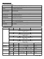
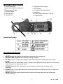
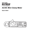
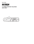
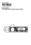
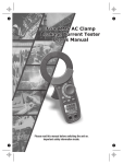
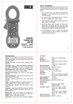
INSTRUCTION MANUAL
Model 380940
DC / AC True RMS Watt Clamp DMM
• 10W or 100mA resolution
• Large 3 3/4 digit LCD display with 40 segment bargraph
• Frequency Measurements
• One touch DCA zero adjust
• MIN/MAX and Data Hold functions
• 0.9” (23mm) Jaw diameter
1. INTRODUCTION
Congratulations on your purchase of Extech’s Watt Clamp Meter. This professional meter, with proper
care, will provide years of safe reliable service.
2. SPECIFICATIONS
2.1 General Specifications
Display
3-3/4 (4000 count) Digit LCD with 40 segment bargraph
Functions
Watts, ACA, DCA, ACV, DCV, Frequency
Polarity
“-“ indicates negative polarity
Current sensor
Hall effect sensor type
Overload indication
Left blinking digit
DCA zero adjust
One touch zero key
Display rate
2 readings/second (20 readings/second for bargraph)
Auto Power Off
30 minutes after power ON
Battery
Two 1.5V AA batteries
Operating temp.
40F to 1220F (-100C to 500C)
Operating Humidity
< 85% RH
Power consumption
Approximately 10mA DC
Weight
6.7 oz. (190g) including battery
Dimensions
7.2 x 2.5 x 1.4” (183 x 63.6 x 35.6mm) (HWD)
Jaw opening
0.9” (23mm)
Standards
IEC 1010 Category III 300V, Category II 600V
2.2 Range Specifications
Function
AC Power
Range
40kW
Resolution
Accuracy
10W
Overload protect
±1.5% ±3dgts
See note
Note 50/60Hz, 0-250V, 0-400A, PF 0-1,
Vpeak < 360V
240kW
100W
±1.5% ±3dgts
See note
Note 50/60Hz, 0-600V, 0-400A, PF 0-1,
Vpeak < 850V
40kW
10W
±2.5% ±3dgts
See note
Note 40Hz – 1KHz, 0-250V, 0-400A, PF 0-1,
Vpeak < 360V
240kW
100W
±2.5% ±3dgts
See note
Note 40Hz – 1KHz ,0-600V, 0-400A, PF 0-1,
Vpeak < 850V
DC Power
DC Current
40kW
10W
±1.5% ±3dgts
240kW
100W
±1.5% ±3dgts
400A
100mA
±1.5% ±3dgts
AC Current
DC Voltage
400A
100mA
400V
0.1V
AC Voltage
Frequency
50/60Hz
40 – 1kHZ
±1.5% ±3dgts
±2.5% ±4dgts
±1.0% ±2dgts
50/60Hz
40 to 200Hz
0-250V, 0-400A
600A DC
600A AC
800V DC
600V
1V
±1.5% ±2dgts
±2.0% ±4dgts
800V AC
100 to
1000k
0.01Hz
±0.8% ±2dgts
Sens. 10V
600V AC
2
Ver. 2.0
12/02
3. FRONT PANEL DESCRIPTION
1. Current sense jaw
(shown with conductor inside jaw)
2. Measurement Trigger
3. Function switch
4. Data Hold key
5. Max Min key
6. One-touch DCA zero key
7. LCD Display
8. 40 segment bargraph display
9. Handstrap
10. Positive input terminal for V,W,HZ
11. COM terminal
International Symbols
4. SAFETY INSTRUCTIONS
1. NEVER exceed the specified voltage/current maximum when measuring
2. USE EXTREME CAUTION when working with high voltages.
3. DO NOT measure voltage if the voltage on the "COM" input jack exceeds 500V above earth
ground.
4. NEVER connect the meter leads across a voltage source while the function switch is in the current
mode. Doing so can damage the meter.
5. ALWAYS discharge filter capacitors in power supplies and disconnect the power when
measuring.
6. ALWAYS turn off the power and disconnect the test leads before opening the back to replace the
fuse or batteries.
7. NEVER operate the meter unless the back cover and the battery/fuse door are in place and
fastened securely.
3
Ver. 2.0
12/02
5. OPERATION
5.1 AC+DC Power /. Watt Measurements
1) Connect the test leads to the voltage source in parallel
with the load
2) Clamp on one of the wires to the load.
3) Select AC or DC voltage range and check the voltage
reading.
4) Select the AC or DC current range, and check the
current reading.
5) Select the appropriate Watt range.
6) Read the KW value shown on the LCD.
5.2 AC Current Measurements
WARNING: To avoid electric shock, disconnect the test leads from the meter before making current
measurements.
1) Set the Function switch to the 400A AC range.
2) Press the jaw trigger and clamp around a single conductor fully enclosing it. Do not allow a
gap between the two halves of the jaw.
3) Read the ACA value on the LCD.
5.3 DC Current Measurements
WARNING: To avoid electric shock, disconnect the test leads from the meter before making current
measurements.
1) Set the Function switch to the 400A DC range.
2) Press the DCA zero key to null the meter display.
3) Press the jaw trigger and clamp around a single conductor fully enclosing it. Do not allow a
gap between the two halves of the jaw.
4) Read the DCA value on the LCD.
5.4 AC Voltage Measurements
WARNING: To avoid electric shock or damage to the meter, do not make any voltage
measurements that exceed the maximum specified.
1) Set the Function switch to the VAC position.
2) Insert the test leads to the meter as follows: Red lead to “V,W,Hz” terminal; Black lead to the
COM input.
3) With the pointed end of the test leads measure voltage. Remember that voltage
measurements are made in parallel with the device/circuit under test.
4) Read the ACV value on the LCD.
4
380940
Ver. 1.3
8/99
5.5 DC Voltage Measurements
WARNING: To avoid electric shock or damage to the meter, do not make any voltage
measurements that exceed the maximum specified.
1) Set the Function switch to the VDC position.
2) Insert the test leads to the meter as follows: Red lead to “V,W,Hz,” terminal; Black lead to the
COM input.
3) With the pointed end of the test leads measure voltage. Remember that voltage
measurements are made in parallel with the device or circuit under test.
4) Read the DCV value on the LCD.
5.6 Frequency Measurements
1)
2)
3)
4)
Set the Function switch to the Hz position.
Insert the test leads into the meter’s input terminals.
Connect the other ends of the test leads in parallel with the device/circuit under test.
Read the Frequency measurement on the LCD in Hz.
6. ADVANCED FEATURES
6.1 Relative Measurements
1) Press the Zero key and the present measurement will Zero.
2) All subsequent measurements are displayed with respect to the zeroed reading. For example,
if a 20A reading is zeroed and a 30A reading is subsequently measured, the LCD will display
10A.
3) To return to normal operation, press and hold the zero key for 2 seconds.
4) Note that Relative mode is not available if MIN/MAX mode is enabled.
6.2 Data Hold
To freeze the current reading on the LCD, press the Data Hold key. To release the Data Hold
function and return the meter to normal operation, press the Data Hold key again.
6.3 MIN/MAX Readings
Pressing the MIN/MAX key allows the meter to display ONLY the highest and the lowest readings
encountered. Press the MIN/MAX key once to view the minimum reading, press it again to view
the maximum reading. Note that the meter will only change its displayed reading when a
measurement is taken higher than the previous MAX or lower than the previous MIN readings.
The HOLD display icon (along with the MIN or MAX icon) will appear on the LCD in MIN/MAX
mode Pressing the MIN/MAX key a 3rd time returns the meter to normal operation.
6.4 Auto Power Off
To extend battery life, the meter will auto power off after 30 minutes of operation. To resume
operation either turn the meter OFF and then ON again or press the HOLD button.
5
380940
Ver. 1.3
8/99
7. MAINTENANCE
7.1 Battery Replacement
1)
2)
3)
4)
When the low battery symbol appears on the LCD, the batteries must be replaced.
Power down and remove the rear battery compartment screw.
Lift off the battery compartment cover and replace the two 1.5V AA cells.
Replace compartment cover and secure the screw.
7.2 Cleaning
Caution: Use only a dry cloth to clean the plastic case.
8. CALIBRATION / REPAIR SERVICES
Extech offers complete repair and calibration services for all of the products we sell. For periodic
calibration, NIST certification or repair of any Extech product, call customer service for details on
services available. Extech recommends that calibration be performed on an annual basis to insure
calibration integrity.
9. WARRANTY
EXTECH INSTRUMENTS CORPORATION warrants this instrument to be free of defects in parts and workmanship for
one year from date of shipment (a six month limited warranty applies on sensors and cables). If it should become
necessary to return the instrument for service during or beyond the warranty period, contact the Customer Service
Department at (781) 890-7440 for authorization. A Return Authorization (RA) number must be issued before any product
is returned to Extech. The sender is responsible for shipping charges, freight, insurance and proper packaging to
prevent damage in transit.
This warranty does not apply to defects resulting from action of the user such as misuse, improper wiring, operation
outside of specification, improper maintenance or repair, or unauthorized modification. Extech specifically disclaims any
implied warranties or merchantability or fitness for a specific purpose and will not be liable for any direct, indirect,
incidental or consequential damages. Extech's total liability is limited to repair or replacement of the product. The
warranty set forth above is inclusive and no other warranty, whether written or oral, is expressed or implied.
Copyright © 2002 Extech Instruments Corporation. All rights reserved including the right of
reproduction in whole or in part in any form.
Tech Support Hotlines
781-890-7440 ext. 200
[email protected]
www.extech.com
6
380940
Ver. 1.3
8/99