1
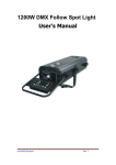
Beijing Huahuan Electronics Co., Ltd H0EL-EthMux V2 V0 White Paper (TDM over IP) 1. Brief Introduction This white paper is help supported for user manual of H0EL-EthMux V2 and V0, and given useful information for installation. There are two local 10/100BaseT auto-sensed Ethernet ports for H0EL-EthMux V2, which differ from H0EL-EthMux V0. This white paper will focus on H0EL-EthMux V2 and H0EL-EthMux V0. (H0EL-EthMux V4 supports 4E1/T1s, web server configuration and point to multipoint application. H0EL-EthMux V4 white paper will be separately released. ) Table of Models H0EL-EthMux V2 Model H0EL-EthMux V0 H0EL-EthMux V4 1 uplink, 2E1s, 2 User Data Ports 1 uplink, 2E1s 2 uplinks, 4E1/T1s, 2 User Data Ports 2. Operation 2.1 Recommend mode switch setting There are 8 groups of paired setting i.e. mode 0 and mode 1 define a communication pair, as well as 2/3, 4/5, E/F. The even/odd are paired (1+even=odd). Recommend mode switch setting is 2/3 mode (one side H0EL-EthMux is mode 2, another is mode 3). Please refer to section 5 interoperability with wireless LAN bridges”. 2.2 Rough estimate of time delay Here is rough estimate of time delay (not included wireless LAN bridges link). The time delay of E1 link unilateralism rough estimated as follow, Time delay =X+Y+Z. X= Fixup delay, about 1.5ms. Y= Packet delay. If packet size is n×128 byte, then Y≈n/2 (ms) Z= Jitter Buffer Size delay. The m= Jitter Buffer Size =1~80, Z= m/2 (ms). Then, Time delay =X+Y+Z ≈1.5+n/2+m/2 (ms). For example, mode switch setting is 2/3 mode, packet size is 3×128 byte (n=3), H0EL-EthMux V2 V0 White Paper (TDM over IP) 1/5 Beijing Huahuan Electronics Co., Ltd Jitter Buffer Size is 30 (m=30), so Time delay ≈1.5+3/2+30/2 =18 (ms). Mode switch setting is 4/5 mode, packet size is 11×128 byte (n=11), Jitter Buffer Size is 30 (m=30), so Time delay ≈1.5+11/2+30/2 =22 (ms). If uplink connection uses wireless LAN bridges, the time delay of E1 link unilateralism need add delay of wireless LAN bridges link. Optimized Jitter Buffer Size is important for TDM over IP link. Increase Jitter Buffer Size will be better to resist packet delay variation (PDV) of LAN bridge, but increase the time delay of E1 link. Decrease Jitter Buffer Size will decrease the time delay of E1 link, but be worse to resist packet delay variation (PDV). Shortage of jitter buffer to resist packet delay variation (PDV) of LAN bridge will cause E1 error bits. More time delay of E1 link will cause low quality of E1. 2.3 Timing mode setting There are two types of timing mode, through and loop. Both units of H0EL-EthMux are setting to through timing mode works well for all the conditions, although the other option may work better. So, default timing mode through is suggested. Correct timing mode setting is important for smooth operations. In most cases, setting both units to through timing mode is sufficient. But sometimes, setting one unit to loop timing mode may work better. For example, setting the H0EL-EthMux unit connected with the clock master (such as local exchange, master station etc.) to loop mode, and the other unit connected with the clock slave (such as PBX or remote module, slave station etc.) to through mode, is probably better than setting both to through modes. Note: setting the H0EL-EthMux unit connected with the clock slave to through mode is important for link synchronization. 2.4 Bandwidth of uplink packet Bigger E1 packet sizes need more bandwidth of uplink packet for H0EL-EthMux. Example show as follow, E1 packet size as 1×128, 6×128 and 11×128. Packet size Bandwidth No E1 link Use IP header for 1×E1 data packets No IP header for 1×E1 data packets Use IP header for 2×E1 data packets No IP header for 2×E1 data packets 1×128Bytes 6×128Bytes 1.03M 2.85M 0.17M 2.19M 0.09M 2.19M 2.40M 2.11M 2.08M 5.70M 4.37M 4.28M 4.80M 4.22M 4.16M H0EL-EthMux V2 V0 White Paper (TDM over IP) 11×128Byte 2/5 Beijing Huahuan Electronics Co., Ltd 2.5 Support cascade concatenate for more than two E1 ports H0EL-EthMux support cascade concatenate for more than 2 E1 ports, when wireless LAN bridges have enough bandwidth. Show as follow, Wireless LAN bridge E1_1 E1_2 E1_3 E1_4 UPLINK DATA UPLINK Wireless LAN bridge UPLINK DATA E1_1 E1_2 E1_3 E1_4 UPLINK 3. Note 3.1 Mode switch setting With 16 positions numbered 1 through F, users may store up to 16 sets of different parameter combinations, based on their various application requirements. But strongly suggested 8 groups of paired setting i.e. mode 0 and mode 1 define a communication pair, as well as 2/3, 4/5... E/F. The even/odd are paired (1+even=odd). A 16-position rotary Mode Switch is provided on the rear panel of H0EL-EthMux V2. It is used for quick selection of pre-saved parameter settings. For H0EL-EthMux V2, after the Mode Switch is set to a position between 0 and F with screwdriver, please connect the console port on H0EL-EthMux to a PC running hyper terminal with a RS232 cable, and check through console commands. For H0EL-EthMux V0, using console commands in the field “(6) CHANGE MODE” to setting mode. The new mode taked effect need several seconds after qiut menu of “(6) CHANGE MODE” for software V0.0.4. For software V0.0.5 or high, the new mode taked effect just need afform in menu of “(6) CHANGE MODE”. The new mode can check through console commands. 3.2 E1 ports There are 2 sets of E1 ports on the rear panel. Each E1 port has a pair of BNC connectors and a RJ45 socket. The left port is denoted port-A, and the other, port-B. The E1 interface impedance is 75Ω(BNC) or 120Ω(RJ45) adaptive, depending on the cables installed. Make sure that both types of cables are NOT connected at the same time. When only use one E1, please only link port-A and do not link port-B in/out. H0EL-EthMux will auto assign bandwidth for the second E1 when linking E1 port-B in and out with loop cable, which will inferior local LAN traffic or port-A E1 performance. H0EL-EthMux V2 V0 White Paper (TDM over IP) 3/5 Beijing Huahuan Electronics Co., Ltd So please let no-use E1 port-B in and out link null. 3.3 Control the loop back of E1 ports A 2-dip switch is provided on the front panel to control the loop back of E1 ports. Either local (LLop) or remote (RLop) loop back can be set by this switch. Command from the remote has a higher priority. So if RLop dip is pressed down on the remote box, the local dip position of LLop will not take effect. One cannot let the system to perform both LLop and RLop at the same time. Instead, if both dips are pressed down for more than 20 seconds, the device will reset all user definable parameters to default settings. The LLop and RLop dip switches will be helpful for installation test. 3.4 Comeback default settings The LLop and RLop dip switches both pressed down for more than 30 seconds, the device will reset all user definable parameters to default settings. Then the dip switches both pressed up, the default settings become effective. Pay attention to the 16-position rotary Mode Switch setting on the rear panel of H0EL-EthMux V2. 3.5 Save current setting Current setting of packet size, timming mode or jitter buffer size be affirmed in menu of “(5) SAVE CONFIG” through console commands. H0EL-EthMux need take several minutes auto gradually to reach the value of jitter buffer. 3.6 Grounding Grounding screw used to connect the chassis to the protective ground. Please credibly connect ground screw of H0EL-EthMux to the room protective ground, also other equipment that link with H0EL-EthMux, for prevent interfere and damaged interface. 3.7 Avoid lightning strikes When connecting to a wireless LAN bridge, the uplink Ethernet cable often connects to the outdoor unit, posing danger to lightning strikes that can seriously damage the equipment. To protect the equipment as well as people, surge protection devices with good earth connection is strongly recommended. Poor earth connection may also hinder the operation of the Ethernet port, causing severe packet losses. 4. Common faults and support When H0EL-EthMux cooperated with many wireless bridges, E1 channel links, but has error. Suggest as follows, a.) Packet loss indicator, red LED “PKTLOS” Blinks. Please check bandwidth of Wireless bridge. Maybe wireless link bandwidth is not enough. H0EL-EthMux V2 V0 White Paper (TDM over IP) 4/5 Beijing Huahuan Electronics Co., Ltd b.) Packet loss indicator, red LED “PKTLOS” is OFF, and red LED “ETHErr” of packet communication status is OFF. Please set more jitter buffer of H0EL-EthMux to resist packet delay variation of wireless bridge link. 5. Interoperability with Wireless Bridges H0EL-EthMux has cooperated with many Wireless bridges, show as follow. More wireless bridges are supported Interoperability Table Wireless Bridges LOGO Manufacturer Place Model H0EL-EthMux V2 & V0 mode switch setting Mode 2/3 (Mode 4/5 also) MOTOROLA USA CANOPY 5700BH, 5700BH20, BH45 etc. Alvarion Israel BREEZENET DS.11, 28B,LBetc Mode 4/5 Proxim USA Tsunami™ MP.11a series, Mode 2/3, Buffer: 80 QuickBridge20 (QB20) etc Mode 6/7 (Mode 2/3 also, but more delay) Ultima 3 series Mode 6/7 (Mode 2/3, 4/5, 8/9 also) Mode 2/3 Wi-Comm United Canada Libra 5800 series Jitter Orthogon Systems, Roots Communications UK, Singapore OS Gemini 58xx Mode 2/3, Buffer: 40 Nanjing Z-Com wireless company China Air Access ZX-5800 ZA-5000, etc. Mode 2/3 (Mode 4/5 also) Infinet Wireless Russia RWR 5000mini Jitter Note: More wireless bridges are supported H0EL-EthMux V2 V0 White Paper (TDM over IP) 5/5