1
AgilentBased MHL Test Adapters User Manual Agilent‐based Mobile High‐
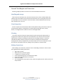
Definition Link Test Adapters User Manual P a g e | 1 ©2011, 2012, 2013, 2014 Wilder Technologies, LLC Document No. 910‐0020‐001 Rev. C AgilentBased MHL Test Adapters User Manual Table of Contents Introduction ..................................................................................................................................... 3 Product Inspection .......................................................................................................................... 4 The MHL Test Adapter Care and Handling Precautions .................................................................. 5 General Test Adapter and Connectors ............................................................................................ 7 Handling and storage................................................................................................................... 7 Visual inspection .......................................................................................................................... 7 Cleaning ....................................................................................................................................... 7 Making Connections .................................................................................................................... 7 Electrostatic Discharge Information ................................................................................................ 8 Application Reference ..................................................................................................................... 9 MHL Source Testing ....................................................................................................................... 10 MHL Direct Source Testing ............................................................................................................ 13 MHL Sink Testing ........................................................................................................................... 16 MHL Sink Calibration ..................................................................................................................... 18 MHL Sink Calibration Electrical Specifications .............................................................................. 23 MHL Dongle Testing ...................................................................................................................... 24 MHL Dongle Calibration ................................................................................................................ 26 MHL Dongle Calibration Electrical Specifications .......................................................................... 31 MHL Cable Testing ......................................................................................................................... 32 MHL RxSen Testing ........................................................................................................................ 34 Other Mechanical and Environmental Specifications ................................................................... 37 Wilder Technologies, LLC – Terms & Conditions of Sale ............................................................... 39 Compliance with Environmental Legislation ................................................................................. 40 WEEE Compliance Statement .................................................................................................... 40 Glossary of Terms .......................................................................................................................... 41 Addendum A – Test Adapters in Support of MHL3 Testing........................................................... 42 MHL3‐TPA‐P‐SOSIS Reference ....................................................................................................... 42 MHL3‐TPA‐P‐SOS Reference .......................................................................................................... 44 Index .............................................................................................................................................. 46 P a g e | 2 ©2011, 2012, 2013, 2014 Wilder Technologies, LLC Document No. 910‐0020‐001 Rev. C AgilentBased MHL Test Adapters User Manual Introduction This user’s guide documents the functionality of the MHL Test Adapters. It is comprised of segments indicating the operation of Source, Sink, Dongle, Cable and RxSen tested against the MHL Compliance Test Specification. These are achieved by differing combinations of:
The Agilent Source/Sink Termination (MHL‐TPA‐AT),
The Micro‐USB plug to SMA with Micro‐USB receptacle for VBUS and CBUS (MHL‐TPA‐P‐WOSO),
The Micro‐USB receptacle to SMA with HDMI receptacle for VBUS and CBUS (MHL‐TPA‐R‐WOSO),
The HDMI receptacle to SMA with Micro‐USB receptacle for VBUS and CBUS (MHL‐TPA‐R‐WOSOD),
The Micro‐USB receptacle to SMA with SMAs for VBUS and CBUS (MHL‐TPA‐R‐WOC),
The HDMI receptacle to SMA with SMAs for VBUS and CBUS (MHL‐TPA‐R‐WOSI),
The HDMI plug to SMA with HDMI receptacle for VBUS and CBUS (MHL‐TPA‐P‐WOSI),
The HDMI receptacle to Micro‐USB receptacle (MHL‐TPA‐R‐SO‐RSEN),
The HDMI receptacle to Micro‐USB receptacle (MHL‐TPA‐R‐SI‐RSEN),
The HDMI plug to SMA with SMAs for VBUS, CBUS, CLK+, and CLK‐ (MHL3‐TPA‐P‐SOSIS),
And the Micro‐USB plug to SMA with SMAs for VBUS and CBUS (MHL3‐TPA‐P‐SOS) The Source/Sink Termination test adapter assemblies allow easy access, via SMA connections for the Agilent N5380A, for differential or single ended testing. It also has square pins for connecting an Agilent E2678A socketed probe head for common mode tests. Please refer to the Agilent MHL MOI for further details of this testing. NOTE: To avoid damaging the MHL‐TPAs, use the handling techniques described in the Care and Handling section before making any connections or configuring a test setup. Always use a static‐safe workstation when performing tests, as explained in the “Electrostatic Discharge Information” section. NOTE: The metal shell of both the plugs and receptacle for each of the connectors in the MHL‐TPAs are configured at the factory to tie high‐speed ground to chassis ground. P a g e | 3 ©2011, 2012, 2013, 2014 Wilder Technologies, LLC Document No. 910‐0020‐001 Rev. C AgilentBased MHL Test Adapters User Manual Product Inspection Upon receiving the MHL‐TPAs from Wilder Technologies, perform the following product inspection:
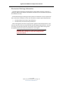
Inspect the outer shipping container, foam‐lined instrument case or storage box, and product for damage. Retain the outer cardboard shipping container until the contents of the shipment have been inspected for completeness and the product has been checked mechanically and electrically. Use the foam‐lined instrument‐case or storage box for secure storage of the Wilder Technologies MHL Test Adapters when not in use. Locate the shipping list and verify that all items ordered were received. In the unlikely event that the product is defective or incomplete, the “Limited Warranty” section discusses how to contact Wilder Technologies for technical assistance and/or how to package the product for return. P a g e | 4 ©2011, 2012, 2013, 2014 Wilder Technologies, LLC Document No. 910‐0020‐001 Rev. C AgilentBased MHL Test Adapters User Manual The MHL Test Adapter Care and Handling Precautions The MHL Test Adapter requires careful handling to avoid damage. Improper handling techniques, or using too small a cable bend radius, can damage the coaxial cable connections themselves. This can occur at any point along the cable. To achieve optimum performance and to prolong the MHL‐TPA’s life, observe the following handling precautions:
CAUTION 1: Avoid Torque Forces (Twisting) Twisting the MHL‐TPA as a unit, with one end held stationary, in excess of +/‐ 90° may damage or severely degrade performance of instrumentation cables. Adherence to Caution 5 (below) helps to avoid exceeding twist limits. CAUTION 2: Avoid Sharp Cable Bends Never bend instrumentation cables beyond the minimum bend radius as specified by the instrumentation cable manufacturer. CAUTION 3: Avoid Cable Tension (Pull Forces) Avoid applying tension to the MHL‐TPA/instrumentation cable interface. Always place the MHL‐TPA and equipment on a surface that allows adjustment to eliminate tension on the MHL‐TPA and attached instrumentation cables. Use adjustable elevation stands or apparatus to accurately place and support the MHL‐TPA and attached instrumentation cables. CAUTION 4: Connect the MHL‐TPA First To prevent twisting, bending, or applying tension to the instrumentation coaxial cables when connecting a MHL‐TPA, always attach the MHL‐TPA to the device under test (DUT) or cable under test before attaching any SMA connectors. Carefully align the MHL connectors and then gently push the connectors together until fully seated. If the MHL‐TPA must be turned or twisted to make connection to the DUT, avoid using the MHL‐TPA housing alone to make this occur. Try to distribute the torque forces along the length of the test setup and cabling. If this is not possible, it is recommended to first loosen or disconnect the SMA connections at the MHL‐TPA, make the connection to the DUT and then re‐tighten or attach the test equipment leads. NOTE: Only grip the test adapter primary connector housing(s) when inserting or extracting the MHL‐TPA to or from the DUT. Pulling directly on the cable under test or using them to insert the MHL‐TPA may cause damage. P a g e | 5 ©2011, 2012, 2013, 2014 Wilder Technologies, LLC Document No. 910‐0020‐001 Rev. C AgilentBased MHL Test Adapters User Manual
CAUTION 5: Carefully Make SMA Connections To connect the MHL‐TPA SMA connectors, follow these steps: 1.
Hold the TPA stationary by grasping the TPA near the SMA connector. 2.
Insert the mating SMA barrel and hand‐tighten the free‐spinning SMA nut onto the connector while avoiding pulling, bending, or twisting the MHL‐TPA coaxial cable. 3.
When attaching instrumentation cables to the MHL‐TPA, it is recommended that the MHL‐TPA SMA connectors be mechanically held and the test leads be tightened to the equipment manufacturer’s torque recommendations, normally 5 in‐lbs, using a 5/16‐inch open‐end wrench. If the test set‐up requires repositioning, first loosen or disconnect the SMA connections to avoid twisting, bending, or tension.
CAUTION 6: Independently Support Instrument Cables Excessive weight from instrumentation cables connected to the MHL‐TPA can cause damage or affect the test adapter performance. Be sure to provide appropriate means to support and stabilize all test set‐up components. P a g e | 6 ©2011, 2012, 2013, 2014 Wilder Technologies, LLC Document No. 910‐0020‐001 Rev. C AgilentBased MHL Test Adapters User Manual General Test Adapter and Connectors Observing simple precautions can ensure accurate and reliable measurements. Handling and storage Before each use of the MHL‐TPA, ensure that all connectors are clean. Handle all MHL‐TPAs carefully and store the MHL‐TPA in the foam‐lined instrument case or storage box when not in use, if possible. Do not set connectors contact end down. Install the SMA protective end caps when the MHL‐TPA is not in use. Visual inspection Be sure to inspect all instrumentation cables carefully before making a connection. Inspect all instrumentation cables for metal particles, scratches, deformed threads, dents, or bent, broken, or misaligned center conductors. Do not use damaged cables. Cleaning If necessary, clean the connectors using low‐pressure (less than 60 PSI) compressed air or nitrogen with an effective oil‐vapor filter and condensation trap. Clean the instrumentation cable threads, if necessary, following the manufacturers cleaning procedures. If necessary, clean MHL‐TPA SMA connectors using a lint‐free swab or cleaning cloth moistened with isopropyl alcohol. Always completely dry a connector before use. Do not use abrasives to clean the connectors. Re‐inspect connectors, making sure no particles or residue remains. Making Connections Before making any connections, review the “Care and Handling Precautions” section. Follow these guidelines when making connections:
Align cables carefully Make preliminary connection lightly To tighten, turn connector nut only Do not apply bending force to instrumentation cables Do not over‐ tighten preliminary connections Do not twist cables Use an appropriately sized torque wrench, and do not tighten past the “break” point of the torque wrench P a g e | 7 ©2011, 2012, 2013, 2014 Wilder Technologies, LLC Document No. 910‐0020‐001 Rev. C AgilentBased MHL Test Adapters User Manual Electrostatic Discharge Information Protection against electrostatic discharge (ESD) is essential while connecting, inspecting, or cleaning the MHL‐TPA test adapter and connectors attached to a static‐sensitive circuit (such as those found in test sets). Electrostatic discharge can damage or destroy electronic components. Be sure to perform all work on electronic assemblies at a static‐safe work station, using two types of ESD protection:
Conductive table‐mat and wrist‐strap combination Conductive floor‐mat and heel‐strap combination When used together, both of these types provide a significant level of ESD protection. Used alone, the table‐mat and wrist‐strap combination provide adequate ESD protection. To ensure user safety, the static‐safe accessories must provide at least 1 MΩ of isolation from ground. Acceptable ESD accessories may be purchased from a local supplier. WARNING: These techniques for a static‐safe work station should not be used when working on circuitry with a voltage potential greater than 500 volts. P a g e | 8 ©2011, 2012, 2013, 2014 Wilder Technologies, LLC Document No. 910‐0020‐001 Rev. C AgilentBased MHL Test Adapters User Manual Application Reference The MHL‐TPAs support all testing of the MHL CTS PHY. They have been designed specifically for the measurements contained in the CTS PHY, limited only by the specifications, environmental, care and handling as stated in this document. The following examples are suggestions for possible testing setups. Please refer to the MHL CTS PHY and the Agilent MOI for specific details of testing. P a g e | 9 ©2011, 2012, 2013, 2014 Wilder Technologies, LLC Document No. 910‐0020‐001 Rev. C AgilentBased MHL Test Adapters User Manual MHL Source Testing Source Plug with
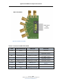
Termination Figure 1. Source Testing block diagram Figure 2. The MHL‐TPA‐AGIL‐SO consists of a MHL‐TPA‐P‐WOSO and a MHL‐TPA‐AT connected as shown P a g e | 10 ©2011, 2012, 2013, 2014 Wilder Technologies, LLC Document No. 910‐0020‐001 Rev. C AgilentBased MHL Test Adapters User Manual MHL‐TPA‐P‐WOSO
MHL‐TPA‐AT High‐Speed Differential Probe Micro USB Plug High‐Speed Common mode Probe Micro USB Receptacle Figure 3. The MHL‐TPA‐P‐WOSO and a MHL‐TPA‐AT Table 1. Connections for the MHL-TPA-P-WOSO
LABEL SIGNAL IDENTIFICATION CONNECTION DESCRIPTION VBus VBus uUSB plug pin 1, jumpered to uUSB receptacle pin 1 MHL‐ Negative MHL signal uUSB plug pin 2 to SMA MHL+ Positive MHL signal uUSB plug pin 3 to SMA CBus CBus (none) GND uUSB plug pin 4, jumpered to uUSB receptacle pin 4 Both uUSB pin 5 and all SMA Shields P a g e | 11 ©2011, 2012, 2013, 2014 Wilder Technologies, LLC Document No. 910‐0020‐001 Rev. C This is the signal from the HDMI based source. This is the signal from the HDMI based source. RF Ground AgilentBased MHL Test Adapters User Manual Table 2. Connections for the MHL –TPA-AT
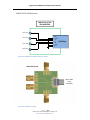
LABEL SIGNAL IDENTIFICATION CONNECTION IO Polarity is determined by connection to source/sink TPA 2 SMAs Probe Polarity is determined by connection to source/sink TPA 2 SMAs (none) Common Mode Output (none) Common mode reference (none) GND Probe Header pin (farthest from the “Vbias” SMA (not installed)) Probe Header pin (closest to the “Vbias” SMA(not installed)) DESCRIPTION This pair of SMA inputs connect the MHL signals to the source TPA or sink TPA. Polarity is determined by this connection. SMA outputs connected to the N5380A probe or SMA cables either differentially or single ended as required by the measurement. Common mode measurement point All SMA shields P a g e | 12 ©2011, 2012, 2013, 2014 Wilder Technologies, LLC Document No. 910‐0020‐001 Rev. C RF Ground RF Ground AgilentBased MHL Test Adapters User Manual MHL Direct Source Testing Direct Source Receptacle with Termination Figure 4. Direct Source Testing block diagram Figure 5. The Direct Source testing uses a MHL‐TPA‐P‐WOSOD and a MHL‐TPA‐AT connected as shown P a g e | 13 ©2011, 2012, 2013, 2014 Wilder Technologies, LLC Document No. 910‐0020‐001 Rev. C AgilentBased MHL Test Adapters User Manual Micro USB Receptacle MHL‐TPA‐AT HDMI Receptacle High‐Speed Differential Probe MHL‐TPA‐R‐WOSOD
High‐Speed Common mode Probe Figure 6. The MHL‐TPA‐P‐WOSOD and a MHL‐TPA‐AT Table 3. Connections for the MHL-TPA-R-WOSOD
LABEL SIGNAL IDENTIFICATION CONNECTION MHL+ Positive MHL signal HDMI receptacle pin 7 to SMA MHL‐ Negative MHL signal HDMI receptacle pin 9 to SMA VBus VBus CBus CBus (none) GND DESCRIPTION This is the signal to the HDMI based sink. This is the signal to the HDMI based sink. HDMI receptacle pin 18, jumpered to uUSB recept pin 1 HDMI receptacle pin 19, jumpered to uUSB recept pin 4 HDMI pins 5, 8, 11, 17, uUSB pin 5, and all SMA Shields P a g e | 14 ©2011, 2012, 2013, 2014 Wilder Technologies, LLC Document No. 910‐0020‐001 Rev. C RF Ground AgilentBased MHL Test Adapters User Manual Table 4. Connections for the MHL –TPA-AT
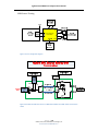
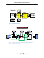
LABEL SIGNAL IDENTIFICATION CONNECTION IO Polarity is determined by connection to source/sink TPA 2 SMAs Probe Polarity is determined by connection to source/sink TPA 2 SMAs (none) Common Mode Output (none) Common mode reference (none) GND Probe Header pin (farthest from the “Vbias” SMA (not installed)) Probe Header pin (closest to the “Vbias” SMA(not installed)) DESCRIPTION This pair of SMA inputs connect the MHL signals to the source TPA or sink TPA. Polarity is determined by this connection. SMA outputs connected to the N5380A probe or SMA cables either differentially or single ended as required by the measurement. Common mode measurement point All SMA shields P a g e | 15 ©2011, 2012, 2013, 2014 Wilder Technologies, LLC Document No. 910‐0020‐001 Rev. C RF Ground RF Ground AgilentBased MHL Test Adapters User Manual MHL Sink Testing Sink Plug without Termination Figure 7. Sink Testing block diagram MHL-TPA-P-WOSI
640-0457-000
5,8,11,17
HDMI
Recep.
19
18
VBUS
CBUS
MHL+ (SMAs’)
2
Agilent
ParBERT
3.3K
50 ohm coaxial cables
7
9
15
HDMI
Plug
To Sink
DUT
18
19
MHL- (SMAs’)
Jumpers
5,
8,
11,
17
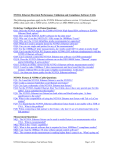
Figure 8. The MHL‐TPA‐P‐WOSI connected as shown P a g e | 16 ©2011, 2012, 2013, 2014 Wilder Technologies, LLC Document No. 910‐0020‐001 Rev. C AgilentBased MHL Test Adapters User Manual MHL‐TPA‐P‐WOSI
HDMI Receptacle
Connector
HDMI Plug Connector High Speed Interface Figure 9. The HDMI plug to SMA with HDMI receptacle for VBUS and CBUS (MHL‐TPA‐P‐WOSI)
Table 5. Connections for the MHL-TPA-P-WOSI
LABEL SIGNAL IDENTIFICATION CONNECTION DESCRIPTION (none) CD sense HDMI plug pin 2 3.3 k ohm to CD pull‐up MHL+ Positive MHL signal HDMI plug pin 7 to SMA MHL‐ Negative MHL signal HDMI plug pin 9 to SMA (none) CD pullup HDMI plug pin 15 VBus VBus CBus CBus (none) GND This is the signal to the HDMI based sink. This is the signal to the HDMI based sink. HDMI plug pin 18, jumpered to HDMI receptacle pin 18 HDMI plug pin 19, jumpered to HDMI receptacle pin 19 Both HDMI pins 5, 8, 11, 17 and all SMA Shields P a g e | 17 ©2011, 2012, 2013, 2014 Wilder Technologies, LLC Document No. 910‐0020‐001 Rev. C 3.3kohm to CD sense RF Ground AgilentBased MHL Test Adapters User Manual MHL Sink Calibration Sink Receptacle with Termination
Sink Plug without Termination
Figure 10. Sink Calibration block diagram Agilent MHL Sink Cal
MHL-TPA-R-WOSI
640-0456-000
MHL-TPA-P-WOSI
640-0457-000
VBUS CBUS
(SMA) (SMA)
HDMI
Recep.
5,8,11,17
MHL+
(SMAs’)
Agilent
ParBERT
CBUS
19
Agilent E2678A
Probe Header
MHL+
(SMA)
18
MHL+
(SMAs’)
VBUS
50 ohm
coaxial
cables
MHL(SMAs’)
MHL-TPA-AT
640-0451-001
3.3K
Jumpers
2
7
9 HDMI
15 Plug
18
19
5,8,
11,17
HDMI
Recep.
70
TP
2
7
9
15
18
19
TP
10
50 ohm
coaxial
cables
300
300
70
1.0pf
Short
Coax
~ 1"
Agilent N5380
Diff. Probe
Agilent
Scope
0
5,8,
11,17
MHL(SMAs’)
MHL(SMA)
10
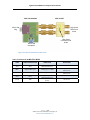
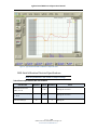
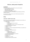
Figure 11. The MHL‐TPA‐AGIL‐SI consists of a MHL‐TPA‐P‐WOSI, MHL‐TPA‐R‐WOSI, and a MHL‐TPA‐AT. They are connected as shown. P a g e | 18 ©2011, 2012, 2013, 2014 Wilder Technologies, LLC Document No. 910‐0020‐001 Rev. C AgilentBased MHL Test Adapters User Manual MHL‐TPA‐P‐WOSI MHL‐TPA‐R‐WOSI
MHL‐TPA‐AT Figure 12. The MHL‐TPA‐P‐WOSI, the MHL‐TPA‐R‐WOSI, and the MHL‐TPA‐AT. Table 6. Connections for the MHL-TPA-P-WOSI
LABEL SIGNAL IDENTIFICATION CONNECTION DESCRIPTION (none) CD sense HDMI plug pin 2 3.3 k ohm to CD pull‐up MHL+ Positive MHL signal HDMI plug pin 7 to SMA MHL‐ Negative MHL signal HDMI plug pin 9 to SMA (none) CD pull‐up HDMI plug pin 15 VBus VBus CBus CBus (none) GND This is the signal to the HDMI based sink. This is the signal to the HDMI based sink. HDMI plug pin 18, jumpered to HDMI receptacle pin 18 HDMI plug pin 19, jumpered to HDMI receptacle pin 19 Both HDMI pins 5, 8, 11, 17 and all SMA Shields P a g e | 19 ©2011, 2012, 2013, 2014 Wilder Technologies, LLC Document No. 910‐0020‐001 Rev. C 3.3kohm to CD sense RF Ground AgilentBased MHL Test Adapters User Manual Table 7. Connections for the MHL-TPA-R-WOSI
LABEL SIGNAL IDENTIFICATION CONNECTION DESCRIPTION (none) CD sense HDMI receptacle pin 2 Test Point to CD sense MHL+ Positive MHL signal MHL‐ Negative MHL signal HDMI receptacle pin 7 to SMA HDMI receptacle pin 9 to SMA This is the signal to the HDMI based sink. This is the signal to the HDMI based sink. (none) CD pull‐up HDMI receptacle pin 15 Test Point to CD pull‐up VBus VBus CBus CBus (none) GND HDMI receptacle pin 18 to SMA HDMI receptacle pin 19 to SMA HDMI pins 5, 8, 11, 17 and all SMA Shields RF Ground Table 8. Connections for the MHL–TPA-AT
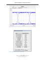
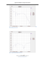
LABEL SIGNAL IDENTIFICATION CONNECTION IO Polarity is determined by connection to source/sink TPA 2 SMAs Probe Polarity is determined by connection to source/sink TPA 2 SMAs (none) Common Mode Output (none) Common mode reference (none) GND Probe Header pin (farthest from the “Vbias” SMA(not installed)) Probe Header pin (closest to the “Vbias” SMA (not installed) DESCRIPTION This pair of SMA inputs connect the MHL signals to the source TPA or sink TPA. Polarity is determined by this connection. SMA outputs connected to the N5380A probe or SMA cables either differentially or single ended as required by the measurement. Common mode measurement point All SMA shields P a g e | 20 ©2011, 2012, 2013, 2014 Wilder Technologies, LLC Document No. 910‐0020‐001 Rev. C RF Ground RF Ground AgilentBased MHL Test Adapters User Manual Figure 13. Typical mated pair 3.0 Gb/s eye diagram Figure 14. Typical mated pair 3.0 Gb/s eye measurements
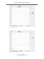
P a g e | 21 ©2011, 2012, 2013, 2014 Wilder Technologies, LLC Document No. 910‐0020‐001 Rev. C AgilentBased MHL Test Adapters User Manual Figure 15. Typical mated pair balanced insertion loss. Attenuation of series10 ohm is measured as -1.75 db.
Hence, the -3db point is -4.75 db.
Figure 16. Typical mated pair balanced return loss P a g e | 22 ©2011, 2012, 2013, 2014 Wilder Technologies, LLC Document No. 910‐0020‐001 Rev. C AgilentBased MHL Test Adapters User Manual Figure 17. Typical Differential TDR of calibration at 100 ps Rise Time
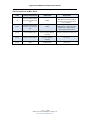
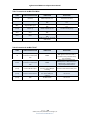
MHL Sink Calibration Electrical Specifications NOTE: All specifications in this manual are subject to change. Table 9. Electrical Specifications, MHL Sink Calibration
SPECIFICATION MINIMUM TYPICAL MAXIMUM Balanced Insertion Loss (GHz), at ‐3 db 7.44 MHL signals on Sink cal Balanced Return Loss (GHz), at ‐20 db 1.29 MHL signals on Sink cal ‐2 2 MHL signals Intra‐lane Skew (ps) NOTES P a g e | 23 ©2011, 2012, 2013, 2014 Wilder Technologies, LLC Document No. 910‐0020‐001 Rev. C AgilentBased MHL Test Adapters User Manual MHL Dongle Testing Source Receptacle without Termination
Figure 18. Dongle Testing block diagram Figure 19. The MHL‐TPA‐R‐WOSO connected as shown P a g e | 24 ©2011, 2012, 2013, 2014 Wilder Technologies, LLC Document No. 910‐0020‐001 Rev. C AgilentBased MHL Test Adapters User Manual MHL‐TPA‐R‐WOSO
HDMI Receptacle
Connector
Micro USB Receptacle High Speed Interface Figure 20. The MHL‐TPA‐R‐WOSO
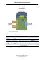
Table 10. Connections for the MHL-TPA-R-WOSO
LABEL SIGNAL IDENTIFICATION CONNECTION DESCRIPTION VBus VBus uUSB recept pin 1, jumpered to HDMI receptacle pin 18 MHL‐ Negative MHL signal uUSB receptacle pin 2 to SMA MHL+ Positive MHL signal uUSB receptacle pin 3 to SMA CBus CBus (none) GND uUSB recept pin 4, jumpered to HDMI receptacle pin 19 uUSB pin 5, HDMI pins 5, 8, 11, 17, and all SMA Shields P a g e | 25 ©2011, 2012, 2013, 2014 Wilder Technologies, LLC Document No. 910‐0020‐001 Rev. C This is the signal from the HDMI based source. This is the signal from the HDMI based source. RF Ground AgilentBased MHL Test Adapters User Manual MHL Dongle Calibration Source Receptacle without Termination
Source Plug with Termination
Figure 21. Dongle Calibration block diagram Agilent MHL Dongle Cal
MHL-TPA-R-WOSO
640-0454-000
MHL(SMAs’)
Agilent
ParBERT
19
CBUS
MHL+
(SMAs’)
18
VBUS
VBUS
MHL+
(SMA)
CBUS
MHL(SMAs’)
10
70
Jump
ers
1
50 ohm
coaxial
cables
Agilent E2678A
Probe Header
Micro USB
Type B
Receptacle
HDMI
Recep.
5,8,1
1,17
MHL-TPA-AT
640-0451-001
MHL-TPA-P-WOSO
640-0453-000
2 Micro USB
Type B
3 Receptacle
4
5
50 ohm
coaxial
cables
Micro USB
Type B
Plug
300
300
70
1.0pf
Short
Coax
~ 1"
Agilent N5380
Diff. Probe
Agilent
Scope
0
MHL+
(SMAs’)
Jumpers
MHL(SMA)
10
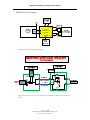
Figure 22. The MHL‐TPA‐AGIL‐DG consists of a MHL‐TPA‐R‐WOSO, the MHL‐TPA‐P‐WOSO, and the MHL‐TPA‐AT. They are connected as shown. P a g e | 26 ©2011, 2012, 2013, 2014 Wilder Technologies, LLC Document No. 910‐0020‐001 Rev. C AgilentBased MHL Test Adapters User Manual MHL‐TPA‐R‐WOSO MHL‐TPA‐P‐WOSO
MHL‐TPA‐AT Figure 23. The MHL‐TPA‐R‐WOSO, the MHL‐TPA‐P‐WOSO, and the MHL‐TPA‐AT. Table 11. Connections for the MHL-TPA-R-WOSO
LABEL SIGNAL IDENTIFICATION CONNECTION DESCRIPTION VBus VBus uUSB recept pin 1, jumpered to HDMI receptacle pin 18 MHL‐ Negative MHL signal uUSB recept pin 2 to SMA MHL+ Positive MHL signal uUSB recept pin 3 to SMA CBus CBus (none) GND uUSB recept pin 4, jumpered to HDMI receptacle pin 19 uUSB pin 5, HDMI pins 5, 8, 11, 17, and all SMA Shields This is the signal from the HDMI based source. This is the signal from the HDMI based source. RF Ground Table 12. Connections for the MHL-TPA-P-WOSO
LABEL SIGNAL IDENTIFICATION CONNECTION DESCRIPTION VBus VBus uUSB plug pin 1, jumpered to uUSB receptacle pin 1 MHL‐ Negative MHL signal uUSB plug pin 2 to SMA MHL+ Positive MHL signal uUSB plug pin 3 to SMA CBus CBus (none) GND uUSB plug pin 4, jumpered to uUSB receptacle pin 4 Both uUSB pin 5 and all SMA Shields P a g e | 27 ©2011, 2012, 2013, 2014 Wilder Technologies, LLC Document No. 910‐0020‐001 Rev. C This is the signal from the HDMI based source. This is the signal from the HDMI based source. RF Ground AgilentBased MHL Test Adapters User Manual Table 13. Connections for the MHL–TPA-AT
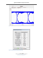
LABEL SIGNAL IDENTIFICATION CONNECTION IO Polarity is determined by connection to source/sink TPA 2 SMAs Probe Polarity is determined by connection to source/sink TPA 2 SMAs (none) Common Mode Output (none) Common mode reference (none) GND Probe Header pin (farthest from the “Vbias” SMA (not installed)) Probe Header pin (closest to the “Vbias” SMA (not installed)) DESCRIPTION This pair of SMA inputs connect the MHL signals to the source TPA or sink TPA. Polarity is determined by this connection. SMA outputs connected to the N5380 probe either differentially or single ended as required by the measurement. Common mode measurement point All SMA shields P a g e | 28 ©2011, 2012, 2013, 2014 Wilder Technologies, LLC Document No. 910‐0020‐001 Rev. C RF Ground RF Ground AgilentBased MHL Test Adapters User Manual Figure 24. Typical mated pair 3.0 Gb/s eye diagram Figure 25. Typical mated pair 3.0 Gb/s eye measurements
P a g e | 29 ©2011, 2012, 2013, 2014 Wilder Technologies, LLC Document No. 910‐0020‐001 Rev. C AgilentBased MHL Test Adapters User Manual Figure 26. Typical mated pair balanced insertion loss. Attenuation of series10 ohm is measured as -1.75 db.
Hence, the -3db point is -4.75 db.
Figure 27. Typical mated pair balanced return loss P a g e | 30 ©2011, 2012, 2013, 2014 Wilder Technologies, LLC Document No. 910‐0020‐001 Rev. C AgilentBased MHL Test Adapters User Manual Figure 28. Typical Differential TDR of calibration at 100 ps Rise Time
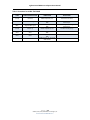
MHL Dongle Calibration Electrical Specifications NOTE: All specifications in this manual are subject to change. Table 14. Electrical Specifications, MHL Dongle Calibration
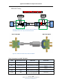
SPECIFICATION MINIMUM TYPICAL MAXIMUM Balanced Insertion Loss (GHz), at ‐3 db 6.2 MHL signals on Dongle cal Balanced Return Loss (GHz), at ‐20 db 0.7 MHL signals on Dongle cal ‐2 2 MHL signals Intra‐lane Skew (ps) NOTES P a g e | 31 ©2011, 2012, 2013, 2014 Wilder Technologies, LLC Document No. 910‐0020‐001 Rev. C AgilentBased MHL Test Adapters User Manual MHL Cable Testing Figure 29. The MHL‐TPA‐AGIL‐CB consists of a MHL‐TPA‐R‐WOC for the source and the TPA‐R‐WOSI for the sink. They are connected as shown. MHL‐TPA‐R‐WOC MHL‐TPA‐R‐WOSI
Figure 30. The MHL‐TPA‐R‐WOC and the MHL‐TPA‐R‐WOSI. Table 15. Connections for the MHL-TPA-R-WOC
LABEL SIGNAL IDENTIFICATION CONNECTION DESCRIPTION VBus VBus uUSB receptacle pin 1 to SMA MHL‐ Negative MHL signal uUSB receptacle pin 2 to SMA MHL+ Positive MHL signal uUSB receptacle pin 3 to SMA CBus CBus uUSB receptacle pin 4 to SMA (none) GND uUSB pin 5, HDMI pins 5, 8, 11, 17, and all SMA Shields RF Ground P a g e | 32 ©2011, 2012, 2013, 2014 Wilder Technologies, LLC Document No. 910‐0020‐001 Rev. C This is the signal from the Agilent ParBERT. This is the signal from the Agilent ParBERT. AgilentBased MHL Test Adapters User Manual Table 16. Connections for the MHL-TPA-R-WOSI
LABEL SIGNAL IDENTIFICATION CONNECTION DESCRIPTION (none) CD sense HDMI receptacle pin 2 Test Point to CD sense MHL+ Positive MHL signal MHL‐ Negative MHL signal HDMI receptacle pin 7 to SMA HDMI receptacle pin 9 to SMA This is the signal to the Agilent Oscilloscope. This is the signal to the Agilent Oscilloscope. (none) CD pull‐up HDMI receptacle pin 15 Test Point to CD pull‐up VBus VBus CBus CBus (none) GND HDMI receptacle pin 18 to SMA HDMI receptacle pin 19 to SMA HDMI pins 5, 8, 11, 17 and all SMA Shields P a g e | 33 ©2011, 2012, 2013, 2014 Wilder Technologies, LLC Document No. 910‐0020‐001 Rev. C RF Ground AgilentBased MHL Test Adapters User Manual MHL RxSen Testing From
Source
DUT
HDMI
Recep.
SW1
MHL(TP)
VBus
(TP)
VBus
SW2
MHL+
(TP)
MHL -
Rpu2
1.6M
Rpu1
1.6M
Vterm
(TP)
MHL +
MHL-TPA-R-SO-RSEN
640-0458-000
18
1
9
2
7
3
19
4
Micro USB
Type B
Receptacle
Cbus Tester
(Sink Emulation)
CBus
GND
5
5,
8,
11,
17
CBus
(TP)
GND
(TP)
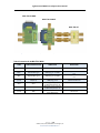
Figure 31. The Source Rx Sense consists of a MHL‐TPA‐R‐SO‐RSEN connected as shown. MHL‐TPA‐R‐SO‐RSEN
Figure 32. The HDMI receptacle to Micro‐USB receptacle (MHL‐TPA‐R‐SO‐RSEN) P a g e | 34 ©2011, 2012, 2013, 2014 Wilder Technologies, LLC Document No. 910‐0020‐001 Rev. C AgilentBased MHL Test Adapters User Manual Table 17. Connections for the MHL-TPA-R-SO-RSEN
LABEL SIGNAL IDENTIFICATION CONNECTION VBus VBus MHL‐ Negative MHL signal MHL+ Positive MHL signal CBus CBus Vterm Termination voltage Test Point For jumpered pull up resistors (none) GND uUSB pin 5, HDMI pins 5, 8, 11, 17, and all SMA Shields RF Ground uUSB receptacle pin 1, to Test Point, and to HDMI receptacle pin 18 uUSB receptacle pin 2, to Test Point, and to HDMI receptacle pin 9 uUSB receptacle pin 3, to Test Point, and to HDMI receptacle pin 7 uUSB receptacle pin 4, to Test Point, and to HDMI receptacle pin 19 P a g e | 35 ©2011, 2012, 2013, 2014 Wilder Technologies, LLC Document No. 910‐0020‐001 Rev. C DESCRIPTION Jumper for 1.6 Mohms to Vterm Jumper for 1.6 Mohms to Vterm AgilentBased MHL Test Adapters User Manual Figure 33. The Sink Rx Sense consists of a MHL‐TPA‐R‐SI‐RSEN connected as shown. MHL‐TPA‐R‐SI‐RSEN
Figure 34. The HDMI receptacle to Micro‐USB receptacle (MHL‐TPA‐R‐SI‐RSEN) P a g e | 36 ©2011, 2012, 2013, 2014 Wilder Technologies, LLC Document No. 910‐0020‐001 Rev. C AgilentBased MHL Test Adapters User Manual Table 18. Connections for the MHL-TPA-R-SI-RSEN
LABEL SIGNAL IDENTIFICATION CONNECTION DESCRIPTION VBus VBus uUSB receptacle pin 1, to Test Point, and to HDMI receptacle pin 18 The SW_RREF1 goes to RREF1_ILEAK (1.0 Mohm) or RREF1_TERM (300 kohm) or RREF1_TMDS (210 ohm), all to GND. The SW_RPU1 goes to RPU1_ILEAK (1.6 Mohm) or RPU1_TERM (100 kohm) or RPU1_TMDS (70 ohm), all to Vterm. The SW_RREF2 goes to RREF2_ILEAK (1.0 Mohm) or RREF2_TERM (300 kohm) or RREF2_TMDS (210 ohm), all to GND. The SW_RPU2 goes to RPU2_ILEAK (1.6 Mohm) or RPU2_TERM (100 kohm) or RPU2_TMDS (70 ohm), all to Vterm. Negative MHL signal uUSB receptacle pin 2, to Test Point, to SW_RREF1, Through the jumper, to SW_RPU1 and to HDMI receptacle pin 9 MHL+ Positive MHL signal uUSB receptacle pin 3, to Test Point, to SW_RREF2, Through the jumper, to SW_RPU2 and to HDMI receptacle pin 7 CBus CBus uUSB receptacle pin 4, to Test Point, and to HDMI receptacle pin 19 Vterm Termination voltage Test Point For jumpered pull up resistors (none) GND uUSB pin 5, HDMI pins 5, 8, 11, 17, and all SMA Shields Ground (all reference resistors are pulled to ground) MHL‐ Other Mechanical and Environmental Specifications NOTE: All specifications in this manual are subject to change. Table 19. General Specifications
ITEM DESCRIPTION Usage Environment Controlled indoor environment Operating Temperature 0°C to +55°C (32°F to +131°F) (Characteristic) Storage Temperature ‐40°C to +70°C (‐40°F to +158°F) (Characteristic) P a g e | 37 ©2011, 2012, 2013, 2014 Wilder Technologies, LLC Document No. 910‐0020‐001 Rev. C AgilentBased MHL Test Adapters User Manual Wilder Technologies, LLC – Limited Warranty Wilder Technologies, LLC warrants that each Test Adapter, 1) is free from defects in materials and workmanship and, 2) conforms to Wilder Technologies specifications for a period of 12 months. See Consumable and Fragile Material Warranty for exceptions to the 12 month warranty The warranty period for a Test Adapter is a specified, fixed period commencing on the date of ship from Wilder Technologies, LLC. If you did not purchase your Test Adapter directly from Wilder Technologies, LLC, the serial number and a valid proof of purchase will be required to establish your purchase date. If you do not have a valid proof of purchase, the warranty period will be measured from the date of ship from Wilder Technologies, LLC. If, during the warranty period, the Test Adapter is not in good working order, Wilder Technologies, LLC will, at its option, repair or replace it at no additional charge, except as is set forth below. In some cases, the replacement Test Adapter may not be new and may have been previously installed. Regardless of the Test Adapter’s production status, Wilder Technologies, LLC appropriate warranty terms apply. Consumable and Fragile Material Warranty Wilder Technologies, LLC warrants that consumable materials and all fragile materials supplied by Wilder Technologies, LLC either as part of an instrument or system, or supplied separately, will be free from defects in material and workmanship at the time of shipment. Extent of Warranty The warranty does not cover the repair or exchange of a Test Adapter resulting from misuse, accident, modification, unsuitable physical or operating environment, improper maintenance by you, or failure caused by a product for which Wilder Technologies, LLC is not responsible. The warranty is voided by removal or alteration of Test Adapter or parts identification labels. The initial three months are unconditional; the remaining months excludes plugs, receptacles and SMA connectors. Connectors are wear items and excluded from the warranty after the initial three months. These warranties are your exclusive warranties and replace all other warranties or conditions, express or implied, including but not limited to, the implied warranties or conditions or merchantability and fitness for a particular purpose. These warranties give you specific legal rights and you may also have other rights which vary from jurisdiction to jurisdiction. Some jurisdictions do not allow the exclusion or limitation of express or implied warranties, so the above exclusion or limitation may not apply to you. In that event, such warranties are limited in duration to the warranty period. No warranties apply after that period. Items Not Covered by Warranty
Wilder Technologies, LLC does not warrant uninterrupted or error‐free operation of a Test Adapter. Any technical or other support provided for a Test Adapter under warranty, such as assistance via telephone with "how‐to" questions and those regarding Test Adapter set‐up and installation, will be provided WITHOUT WARRANTIES OF ANY KIND. Warranty Service Warranty service may be obtained from Wilder Technologies, LLC by returning a Wilder Technologies, LLC Returns Material Authorization and the Test Adapter to Wilder Technologies, LLC during the warranty period. To obtain RMA number, contact support@wilder‐tech.com. You may be required to present proof of purchase or other similar proof of warranty entitlement. You are responsible for any associated transportation charges, duties and insurance between you and Wilder Technologies, LLC. In all instances, you must ship Test Adapters in Wilder Technologies, LLC approved packaging. Information on packaging guidelines can be found at: www.wilder‐tech.com. Wilder Technologies, LLC will ship repaired or replacement Test Adapter Delivery Duty Prepaid (DDP) and will pay for return shipment. You will receive title to the repaired or replacement Test Adapter and you will be the importer of record. P a g e | 38 ©2011, 2012, 2013, 2014 Wilder Technologies, LLC Document No. 910‐0020‐001 Rev. C AgilentBased MHL Test Adapters User Manual Wilder Technologies, LLC – Terms & Conditions of Sale 1.
2.
3.
4.
5.
6.
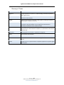
Other Documents: This Agreement may NOT be altered, supplemented, or amended by the use of any other document(s) unless otherwise agreed to in a written agreement signed by both you and Wilder Technologies, LLC. If you do not receive an invoice or acknowledgement in the mail, via e‐mail, or with your Product, information about your purchase may be obtained at support@wilder‐tech.com or by contacting your sales representative. Payment Terms, Orders, Quotes, Interest: Terms of payment are within Wilder Technologies, LLC’s sole discretion, and unless otherwise agreed to by Wilder Technologies, LLC, payment must be received by Wilder Technologies, LLC prior to Wilder Technologies, LLC's acceptance of an order. Payment for the products will be made by credit card, wire transfer, or some other prearranged payment method unless credit terms have been agreed to by Wilder Technologies, LLC. Invoices are due and payable within the time period noted on your invoice, measured from the date of the invoice. Wilder Technologies, LLC may invoice parts of an order separately. Your order is subject to cancellation by Wilder Technologies, LLC, in Wilder Technologies, LLC’s sole discretion. Unless you and Wilder Technologies, LLC have agreed to a different discount, Wilder Technologies, LLC’s standard pricing policy for Wilder Technologies, LLC‐branded systems, which includes hardware, software and services in one discounted price, allocates the discount off list price applicable to the service portion of the system to be equal to the overall calculated percentage discount off list price on the entire system. Wilder Technologies, LLC is not responsible for pricing, typographical, or other errors in any offer by Wilder Technologies, LLC and reserves the right to cancel any orders resulting from such errors. Shipping Charges; Taxes; Title; Risk of Loss: Shipping, handling, duties and tariffs are additional unless otherwise expressly indicated at the time of sale. Title to products passes from Wilder Technologies, LLC to Customer on shipment from Wilder Technologies, LLC’s facility. Loss or damage that occurs during shipping by a carrier selected by Wilder Technologies, LLC is Wilder Technologies, LLC’s responsibility. Loss or damage that occurs during shipping by a carrier selected by you is your responsibility. You must notify Wilder Technologies, LLC within 7 days of the date of your invoice or acknowledgement if you believe any part of your purchase is missing, wrong or damaged. Unless you provide Wilder Technologies, LLC with a valid and correct tax exemption certificate applicable to your purchase of Product and the Product ship‐to location, you are responsible for sales and other taxes associated with the order. Shipping dates are estimates only. WARRANTY: WILDER TECHNOLOGIES, LLC, warrants that the item(s) manufactured under the Buyer’s contract shall be free from defects in materials and workmanship furnished by WILDER TECHNOLOGIES, LLC, and shall conform to the applicable drawings and specifications. WILDER TECHNOLOGIES, LLC’S liability herein, for breach of warranty, contract or negligence in manufacturing, shall be limited to repair or replacement. Repair or replacement of defective items will be applicable only if the Buyer notifies WILDER TECHNOLOGIES, LLC, by written notice within 30‐days of delivery. All claims shall be addressed to: support@wilder‐tech.com or WILDER TECHNOLOGIES, LLC, 6101A East 18th Street, Vancouver, Washington 98661 U.S.A.; ATTENTION: Customer Service Manager. WILDER TECHNOLOGIES, LLC, reserves the right to inspect at the Buyer’s plant all items claimed to be defective or nonconforming prior to authorizing their return. WILDER TECHNOLOGIES, LLC, assumes no liability for the results of the use of its components in conjunction with other electric, electronic or mechanical components, circuits and/or systems. The foregoing constitutes the sole and exclusive remedy of the Buyer and the exclusive liability of WILDER TECHNOLOGIES, LLC, and is IN LIEU OF ANY AND ALL OTHER WARRANTIES, STATUTORY, IMPLIED OR EXPRESSED AS TO MERCHANTABILITY, FITNESS FOR THE PURPOSE SOLD, DESCRIPTION, QUALITY, and PRODUCTIVENESS OR ANY OTHER MATTER. Without limiting the foregoing, in no event shall WILDER TECHNOLOGIES, LLC, be liable for loss of use, profit or other collateral, or for special and/or consequential damages. RETURNED GOODS: WILDER TECHNOLOGIES, LLC, will accept only those goods for return that have been authorized for return. All goods authorized for return shall be assigned a Returned Material Authorization (RMA) Number. The RMA Number shall be clearly marked on the shipping container(s) and all documentation accompanying the goods authorized for return. The RMA Number shall be assigned by WILDER TECHNOLOGIES, LLC pursuant to the conditions set forth in Paragraph 4, WARRANTY. UNITED STATES GOVERNMENT CONTRACTS: In the event this offer is accepted under Government contract, WILDER TECHNOLOGIES, LLC, agrees to accept clauses required by Government regulations and to waive WILDER TECHNOLOGIES, LLC conditions inconsistent therewith. WILDER TECHNOLOGIES, LLC, certifies that it is a regular manufacturer or dealer of the goods and/or services offered herein and that the prices offered do not exceed those charged to any customer for like quantities, services or materials under the same conditions. P a g e | 39 ©2011, 2012, 2013, 2014 Wilder Technologies, LLC Document No. 910‐0020‐001 Rev. C AgilentBased MHL Test Adapters User Manual Compliance with Environmental Legislation Wilder Technologies, LLC, is dedicated to complying with the requirements of all applicable environmental legislation and regulations, including appropriate recycling and/or disposal of our products. WEEE Compliance Statement The European Union adopted Directive 2002/96/EC on Waste Electrical and Electronic Equipment (WEEE), with requirements that went into effect August 13, 2005. WEEE is intended to reduce the disposal of waste from electrical and electronic equipment by establishing guidelines for prevention, reuse, recycling and recovery. Wilder Technologies has practices and processes in place to conform to the requirements in this important Directive. In support of our environmental goals, effective January 1st, 2009 Wilder Technologies, LLC has partnered with EG Metals Inc. – Metal and Electronics Recycling of Hillsboro, Oregon, www.egmetalrecycling.com, to recycle our obsolete and electronic waste in accordance with the European Union Directive 2002/96/EC on waste electrical and electronic equipment ("WEEE Directive"). As a service to our customers, Wilder Technologies is also available for managing the proper recycling and/or disposal of all Wilder Technologies products that have reached the end of their useful life. For further information and return instructions, contact support@wilder‐tech.com. P a g e | 40 ©2011, 2012, 2013, 2014 Wilder Technologies, LLC Document No. 910‐0020‐001 Rev. C AgilentBased MHL Test Adapters User Manual Glossary of Terms TERMINOLOGY DEFINITION Aggressor A signal imposed on a system (i.e., cable assembly) to measure response on
other signal carriers. Cable MHL Cable with micro‐USB connector on the source end and HDMI Type‐A connector on the sink end. Dongle A protocol converter for conversion of MHL (USB micro‐B plug connector) to HDMI (Type‐A receptacle connector). MHL‐TPA MHL Test Point Access. A specialized assembly that interfaces to a MHL
receptacle or plug and enables access to signals for measurement or stimulation. Also allows access to VBus and CBus. Informative The designation of a test that is not required for compliance but is considered
important from a characterization standpoint. It is provided for informational purposes only. Normative The designation of a test that is required for compliance. RxSen DC Parametric measurements
Sink Device A device that contains A/V stream sinks for display and/or sound. Source Device A device that contains a stream source and originates an isochronous A/V
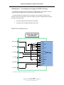
stream. Victim A signal carrier on a system that has a response imposed on it by other signals in the system. P a g e | 41 ©2011, 2012, 2013, 2014 Wilder Technologies, LLC Document No. 910‐0020‐001 Rev. C AgilentBased MHL Test Adapters User Manual Addendum A – Test Adapters in Support of MHL3 Testing This addendum provides reference information for additional MHL Test Adapters to further support testing to the MHL Version 3 Compliance Test Specification (CTS). The following listed test adapters further compliment the test adapters described in the previous sections of this document. Refer to the MHL CTS PHY and the Agilent MOI for specific usage and test model details.
The SMA to HDMI‐A Plug TPA (MHL3‐TPA‐P‐SOSIS)
The SMA to Micro‐USB plug TPA (MHL3‐TPA‐P‐SOS) MHL3‐TPA‐P‐SOSIS Reference MHL3‐TPA‐P‐SOSIS
640‐0486‐000
MHL+ (SMA)
49.9
MHL‐ (SMA)
49.9
49.9
49.9
CLK+ (SMA)
CLK‐ (SMA)
3.3K
VBUS (SMA)
CBUS (SMA)
Figure A-1. The MHL3‐TPA‐P‐SOSIS connected as shown P a g e | 42 ©2011, 2012, 2013, 2014 Wilder Technologies, LLC Document No. 910‐0020‐001 Rev. C SHELL
1 D2+
2 D2 Shield
3 D2‐
4 D1+
5 D1 Shield
6 D1‐
7 D0+
8 D0 Shield
9 D0‐
HDMI Plug
10 CK+ 11 CK Shield
12 CK‐
13 CE Remote
14 NC
15 DDC CLK
16 DDC DATA
17 GND
18 +5V
19 HP DET
SHELL
AgilentBased MHL Test Adapters User Manual MHL3‐TPA‐P‐SOSIS HDMI Type A Plug Connector Figure A-2. The MHL3‐TPA‐P‐SOSIS Table A-1. Connections for the MHL3-TPA-P-SOSIS
LABEL SIGNAL IDENTIFICATION CONNECTION DESCRIPTION (none) Ground HDMI Plug Shell and Pins 5, 8, 11, 17 and all SMA Shields RF Ground MHL+ Positive MHL signal HDMI Plug pin 7 to SMA MHL‐ Negative MHL signal HDMI Plug pin 9 to SMA CLK+ Positive Clock Signal HDMI Plug pin 10 to SMA CLK‐ Negative Clock Signal HDMI Plug pin 12 to SMA (none) CD pull‐up HDMI Plug pin 15 VBUS VBus HDMI Plug pin 18 to SMA Power CBUS CBus HDMI Plug pin 19 to SMA P a g e | 43 ©2011, 2012, 2013, 2014 Wilder Technologies, LLC Document No. 910‐0020‐001 Rev. C This is a TMDS signal from the Agilent AWG or ParBert. This is a TMDS signal from the Agilent AWG or ParBert. This is a TMDS clock from the Agilent AWG or ParBert. This is a TMDS clock from the Agilent AWG or ParBert. Test Point to CD pull‐up for MHL detection AgilentBased MHL Test Adapters User Manual MHL3‐TPA‐P‐SOS Reference MHL3‐TPA‐P‐SOS
640‐0487‐000
VBUS (SMA)
SHELL
1 VBUS
2 D‐
3 D+
4 ID
5 GND
SHELL
MHL‐ (SMA)
MHL+ (SMA)
µUSB Plug
CBUS (SMA)
Figure A-3. The MHL3‐TPA‐P‐SOS connected as shown MHL3‐TPA‐P‐SOS
Micro USB Plug Connector Figure A-4. The MHL3‐TPA‐P‐SOS P a g e | 44 ©2011, 2012, 2013, 2014 Wilder Technologies, LLC Document No. 910‐0020‐001 Rev. C AgilentBased MHL Test Adapters User Manual Table A-2. Connections for the MHL3-TPA-P-SOS
LABEL SIGNAL IDENTIFICATION CONNECTION DESCRIPTION VBus VBus uUSB plug pin 1 to SMA MHL‐ Negative MHL signal uUSB plug pin 2 to SMA MHL+ Positive MHL signal uUSB plug pin 3 to SMA CBus CBus uUSB plug pin 4 to SMA (none) GND uUSB plug shell and pin 5, and all SMA shields RF Ground This is the signal to the Agilent High‐
Bandwidth Digital Oscilloscope. This is the signal to the Agilent High‐
Bandwidth Digital Oscilloscope. P a g e | 45 ©2011, 2012, 2013, 2014 Wilder Technologies, LLC Document No. 910‐0020‐001 Rev. C AgilentBased MHL Test Adapters User Manual Index Addendum A ‐ TPAs Supporting MHL3 (Prelim.), 42 Agilent MOI, 9, 42 Cable Bend Limits, 5 Cable Tension (Pull Forces), 5 Cable Twisting (Torque), 5 Care and Handling, 5 Cleaning, 7 Compliance WEEE, 40 Connections MHL‐TPA to DUT, 5 SMA, 6 Electrostatic Discharge Information (ESD), 8 ESD Protection, 8 Glossary, 41 Handling and Storage, 7 Making Connections, 7 Mechanical and Environmental Specifications, 37 MHL CTS PHY, 9, 42 MHL Dongle Calibration Electrical Specifications, 31 MHL Sink Calibration Electrical Specifications, 23 Product Inspection, 4 Product Return, 4 Secure Storage, 4 Support, 39 Supporting Instrument Cables, 6 Tables Connections, MHL‐TPA‐AT, 12, 15, 20, 28 Connections, MHL‐TPA‐P‐SOS, 45 Connections, MHL‐TPA‐P‐SOSIS, 43 Connections, MHL‐TPA‐P‐WOSI, 17, 19 Connections, MHL‐TPA‐P‐WOSO, 11, 27 Connections, MHL‐TPA‐R‐SI‐RSEN, 37 Connections, MHL‐TPA‐R‐SO‐RSEN, 35 Connections, MHL‐TPA‐R‐WOC, 32 Connections, MHL‐TPA‐R‐WOSI, 20, 33 Connections, MHL‐TPA‐R‐WOSO, 25, 27 Connections, MHL‐TPA‐R‐WOSOD, 14 Electrical Specifications, MHL Dongle Calibration, 31 Electrical Specifications, MHL Sink Calibration, 23 General Specifications, 37 Terms and Conditions of Sale, 39 Visual Inspection, 7 Warranty, 38 Web Sites support@wilder‐tech.com, 38, 39 www.etechrecycling.com, 40 www.wilder‐tech.com, 38 WEEE, 40 P a g e | 46 ©2011, 2012, 2013, 2014 Wilder Technologies, LLC Document No. 910‐0020‐001 Rev. C Visit our website at www.wilder‐tech.com Wilder Technologies, LLC 6101A East 18th Street Vancouver, WA 98661 Phone: 360‐859‐3041 Fax: 360‐859‐3105 www.wilder‐tech.com ©2011, 2012, 2013, 2014 Wilder Technologies, LLC Document No. 910‐0020‐001 Rev. C Original Document Created: 11/19/2011 Updated: 7/18/2014