1
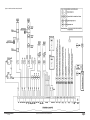
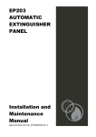
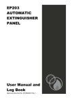
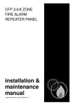
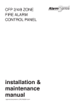
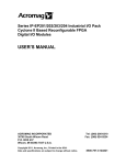
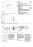
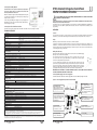
Connecting the Standby Batteries
EP203 Automatic Extinguisher Control Panel
Shortform Installation Instructions
CAUTION: There is a risk of explosion if the battery is replaced by an
incorrect type. Always dispose of used batteries in accordance with
the battery manufacturers’ instructions.
Note: On a standard ‘as-supplied’ unit, PLK1 (‘Battery Monitoring’ link)
is not fitted and a fault will occur on initial power-up if fully charged
batteries are NOT connected.
THIS EQUIPMENT MUST ONLY BE INSTALLED AND MAINTAINED BY A SUITABLY SKILLED AND
TECHNICALLY COMPETENT PERSON.
For the emergency standby power supply, only use good quality, sealed
VRLA batteries. Position and connect the 2x12Vdc, 7Ahr batteries, as
shown in diagram (see right).
This document summarises key information provided in the main Installation and Maintenance Manual (Document No.
DFU0002032). If in doubt, read the full instructions.
The EP203 is a three zone automatic extinguisher control panel that is compliant with EN12094-1 and EN54-2. The
panel incorporates a 3A, EN54-4 compliant switch mode PSU and a 128 x 64 pixel LCD that facilitates system
programming.
Connecting Circuits to the Main Control PCB
Terminate incoming and outgoing circuits at the Main Control PCB connectors (see Figure 2 overleaf).
INSTALLATION
TECHNICAL SPECIFICATION
Location
POWER SUPPLY
Mains supply:
Internal power supply:
Power rating:
230Vac, 50/60Hz @ 810mA max.
24Vdc nominal
Imax. b = 1.5A cont., 3A peak, battery peak current limited by 5A battery fuse
Imax. a = 800mA
Battery type:
YUASA Type NP7-12 (LPCB approved systems); 2 x 12Vdc, 7Ahr VRLA type, connected in series
Battery charge current:
0.7A
Max. battery resistance:
500m ohm
Imin. = 40mA approx.
Quiescent current drain on mains fail:
Mains supply/battery charger monitored for failure: YES
Batteries monitored for disconnection and failure:
YES
Earth fault monitoring:
YES
DETECTOR CIRCUITS
Number of conventional detector circuits:
3
Line monitored for open and short circuit faults:
YES
Max. cable length per circuit:
250m
Zone quiescent detector current per circuit:
2mA max. @ 19-28V
End-of-line resistor value:
6K8 ohm ± 5%, 0.25W
SOUNDER CIRCUITS
Number of conventional sounder circuits:
3 (two x 1st stage, one x 2nd stage)
Line monitored for open and short circuit faults:
YES
Sounder output rating:
19-28Vdc, fused @ 200mA per circuit
Max. sounder cable length per circuit:
50m
Max. number of polarised sounders per circuit:
10 @ 20mA each
End-of-line resistor value:
6K8 ohm ± 5%, 0.25W
MONITORED INPUTS
Number of monitored inputs:
6 (Manual Release, Flow Switch, Low Pressure, Mode, Hold, Abort)
Thresholds:
8k to 2k ohms (normal); 1.8k to 200 ohms (active); 150 to 0 ohms (short-circuit)
End-of-line resistor value:
6K8 ± 5%, 0.25W
AUXILIARY OUTPUTS
Number of auxiliary outputs:*
6 (Fire, Local Fire, Extract, 1st Stage, 2nd Stage, Fault)
Extract time:
Adjustable 1-900 seconds (1 second steps)
Relay contact rating:
30Vdc, 1A max. Note: DO NOT switch mains voltages using these outputs.
* Note: Five additional relay outputs (Reset, Mode, Discharged, Hold, Abort) are available on the EP212 Output Expansion Relay Board.
REMOTE INPUTS
Number of remote inputs:
4 (SIL, AL, FLT, RST)
Auxiliary output:
19-28V, 100mA electronic fuse
EXTINGUISHANT RELEASE OUTPUTS
Extinguishant release output:
19-28Vdc, rated at 1A for 5 mins.
Extinguishant release time delay:
Adjustable 0-60 seconds (1 second steps)
Extinguishant release duration:
Adjustable 1-300 seconds (1 second steps)
Extinguishant release flooding time: Adjustable 60-1740 seconds (1 second steps)
Extinguishant output end-of-line:
System Line Terminator (Part No. EP214)
FUSES Compliant with IEC (EN60127 Pt2)
Mains supply fuse (F1): 1A HRC, 20mm ceramic; Battery fuse (F2): 5A F, 20mm glass; Auxiliary output fuse:100mA electronic; Sounder circuit fuse: 200mA per circuit.
DIMENSIONS & WEIGHT
Physical size (W x H x D):
Back box = 439mm x 276mm x 70mm approx. (metal); Lid = 467mm x 293mm x 29mm approx. (plastic)
Weight:
4.2Kg (without batteries)
ACCESSORIES SUPPLIED WITH PANEL
1 x Shortform Installation Instructions – Document No. DFU0002033 (this document); 1 x Installation and Maintenance Manual - Document No.
DFU0002032; 1 x User Manual/Log Book - Document No. DFU0002031.
1 x Allen key (for unfastening/securing the panel lid); 1 x 1A HRC, 20mm ceramic fuse (spare mains supply fuse F1); 1 x 5A F, 20mm glass fuse
(spare battery fuse F2); 1 x set of links for PLK1 & PLK2; 1 x set of battery connection leads (red lead, black lead, green jump lead).
E&OE. No responsibility can be accepted by the manufacturer or distributors of this equipment for any misinterpretation of this instruction, or for
the compliance of the system as a whole. The manufacturer’s policy is one of continuous improvement and we reserve the right to make changes to
product specifications at our discretion and without prior notice.
EXTINGUISHER PANEL
EP203
Approved Document No. DFU0002033 Rev 4
2 of 3
The panel must be sited indoors on a dry, flat surface in an area that is well ventilated. Ideally the panel indicators
should be at eye level and the ambient light level should allow the status of any indicators to be clearly seen.
Fixing
Note: The panel’s base PCBs should be removed prior to first fix installation.
Using the five mounting holes provided, fix the base securely onto a wall. The mounting holes are suitable for use
with No.8-10, or 4-5mm countersunk screws. Assess the condition and construction of the wall and use suitable screw
fixings. Any dust or swarf created during the fixing process must be kept out of the enclosure and care must be taken
not to damage any wiring or components.
Wiring and Cable Entry
All wiring should be installed in accordance with the current edition of the IEE Wiring Regs
(BS7671), or the relevant national standards.
The requirement for the mains supply to the panel is fixed wiring, using 3-core cable
(no less than 1mm2 and no greater than 2.5mm2), or a suitable three conductor system,
fed from an isolating switched spur, fused at 3A.
In order to maintain cable segregation, the incoming mains cable should be fed into the
panel via the top right hand side knockouts (provided on the base unit). Knockouts should
be removed with a sharp, light tap using a flat 6mm broadsided screwdriver as shown in
diagram (see right). Always ensure that if a knockout is removed, the hole is filled with a
good quality 20mm cable gland. Any unused knockouts must be securely blanked off.
WARNING: DO NOT ATTEMPT TO CONNECT THE MAINS SUPPLY TO THE POWER SUPPLY PCB UNTIL ALL
PCBs ARE SECURELY INSTALLED IN THE ENCLOSURE.
Connecting Mains Supply to the Power Supply PCB
Terminate the mains cable at the Power Supply PCB connector CONN1 (see Figure 1 below).
Figure 1 - Power Supply PCB Layout and Connection Details
Incoming Mains Cable
Must be segregated from other
cables and only enter the panel
through the top RHS knockouts.
Hazardous Voltages Present LED
When lit red, hazardous voltages
are present on the components in
the shaded area of the PCB.
DO NOT TOUCH.
Mains Input (CONN1)
Live = L, Neutral = N, Earth =
CLASS 1 EQUIPMENT MUST BE
EARTHED.
Connect incoming mains earth wire
to the earth terminal and NOT to
the base earth post.
PSU Earth Strap
The PSU earth strap connects the
PCB to the base earth post.
Control Link (PLK2)
Fit PLK2 for 3.5 to 12Ahr,
NOT fitted for 1 to 3.5Ahr.
Control Link (PLK1)
If batteries NOT used, fit PLK1.
Battery Input (CONN6)
Connects to VRLA batteries.
Connector (PL3)
Connects to the Main Control PCB.
EXTINGUISHER PANEL
EP203
Approved Document No. DFU0002033 Rev 4
1 of 3
Figure 2 - Main Control PCB Connection Details
EXTINGUISHER PANEL
EP203
Approved Document No. DFU0002033 Rev 4
3 of 3