1
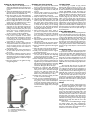
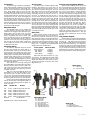
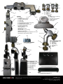
AEROVANE Jig User Manual
™
Congratulations on purchasing the world’s most accurate fletching jig. No more guessing on whether the
fletching is exactly 120 degrees apart. With the Aerovane
Jig system and its accessories, every vane fletched is perfectly spaced every time.
The Aerovane Jig is available in 2 standard packages:
the Enthusiast Set and the Ultimate Set. Additional accessories and optional parts can be purchased to make
the Aerovane Jig meet your individual needs.
Aerovane Jig, and its acces- Enthusiast Set includes:
1. Jig Body
sories available for pur2.Clamp
chase / upgrade (complete
3. Adjustable Neck
list):
4. Base Plate
1. Jig Body
5. 1 Fixed Chuck of your choice
2.Clamp
6. 1 Hook of your choice
3. Adjustable Neck
7. 3 or 4, optional 7 Index
4. Base Plate
5. Fixed Chuck
Ultimate Set includes:
0.166” (for VAP, G nock)
Enthusiast Set plus the following:
0.204” (Axis, Kinetic)
1. All 7 Fixed Chucks
0.225” (H)
2. All 3 Slide Hooks
0.244” (GT, CX)
3. Adjustable Chuck
0.285” (CX bolts)
4. Adjustable Hook
0.300” (Bolts, 22 series)
5. Arrow Leveler
Pin Nock
6. Laser Alignment Module
6. Slide Hook (up to 1.5 degree 7. Long Feather Adaptor
offset capability)
8. 3 or 4, optional 7 Index
0.204” in red (Axis, Kinetic)
9. Deluxe carrying case with wa 0.244” in black (GT, CX)
ter cut foam insert
0.300” in gold (Bolts, 22 series)
7. Adjustable Chuck
8. Adjustable Hook
9. Arrow alignment Leveler
10.Laser Module
11.Camo case with water cut inserts
12.Long Feather Adaptor
13. 3 or 4, optional 7 Index
Adjustable
Chuck
Laser
Module
Long Feather
Adaptor
Arrow
Leveler
Jig Body
Adjustable
Hook
Jig Base
Adjustable
Neck
Aerovane
Clamp
Setting up your Aerovane Jig
1. Attach the Neck to the Base by the brass 1.
Attach the adjustable neck to the base by the
brass knob located on the bottom side of the
jig base.
2. Attach the adjustable neck to the back of the
jig body at the neck attachment point using
the brass knob on the adjustable neck.
3. Place the jig body at your desired fletching
angle. Perfectly horizontal is recommended.
You can achieve the perfect horizontal position by using the level bubble on the jig body.
4. Draw a straight line that is no less than 3
inches long on an unfletched arrow. A silver
Sharpie pen works well for this step.
5. Hold the dial adjustment for the index settings knob in your right hand and push the
marked arrow onto the chuck while slowly
twisting counter-clockwise (away from you).
Ensure the arrow is completely seated on
the chuck.6. Check to ensure your marks
on the arrow line up with the guidelines
7. Place an Aerovane in the clamp. 7. (Note:
If you shoot a compound or recurve bow,
place the back end of Aerovane to the back
end of clamp as far as possible. If you shoot
a crossbow, place the back end of Aerovane
to the letter “K” on the clamp.)
8. Attach clamp to jig body / frame. Push the
clamp down and let it rest completely on the
arrow and make sure the rear end of the
clamp is touching the rear inner section of
the jig body / frame.
9. Look through the top of the clamp, down at
the vane, to line up the marks you made on
the arrow.
10.If you need to adjust the magnets to ensure
the vane lines up with the marks, loosen the
adjustment screw (do not remove), and then
use a small screwdriver to adjust the magnet
either in or out.
11.Once the magnets are set, tighten the magnet tightening knob.
3.2
3.3
3.1
Production neck
3.1 Neck/Base attachment points
3.2 Neck/Jig body attachment points
3.3 Mount screws
Fletching your first Aerovane
1. Once your jig is set with your desired offset,
check to ensure the dial index reads “0”.
2. Thoroughly clean the surface of the shaft by
dipping the shaft into a bottle of 100% pure
acetone.
3. Swirl the shaft in acetone for 10 seconds to
remove all the particles and dissolve all the
possible contaminates on the shaft.
4. Wipe the shaft dry with a clean paper towel.
5. Let air dry till the shaft is ready for fletching.
6. Hold the dial adjustment knob in your right
hand and push the unfletched arrow onto
the chuck while slowly twisting counterclockwise (away from you) and be sure not
to touch the area where you are fletching
as the oils on your hand will contaminate
the shaft). Then check whether the arrow is
completely seated on the chuck.
7. Place an Aerovane in the clamp. (Note: If
you shoot a compound or recurve bow line
up the Aerovane with the back of the clamp
as far as possible. If you shoot a crossbow
line up the Aerovane with the letter “K” on
the clamp.)
8. Dip one end of a Q-tip into the acetone and
wipe down the base of the vane from one
end to the other.
9. Take the dry end of the Q-tip and wipe the
vane dry with the same direction as above.
10.Apply a small bead of glue down the length of
the vane.
11.Place the back end of the clamp against the
inner wall of the jig just above the arrow.
12.Slowly lower the clamp until the magnets
grab hold of the clamp.
13.Firmly push the clamp all the way to the arrow, and wait the allotted time depending
on the type of glue you are using. (Firenock
Aerovane Glue sets in 15 seconds.)
14.After waiting the required time for your specific glue, remove clamp by pinching the top
together with your left hand, then twist the
dial adjustment knob towards the next index
with your right hand. When the arrow rotates about 30 degrees lift the clamp up.
15.Continue to rotate the Dial Adjustment
Knob counter-clockwise (towards yourself)
until you see “120” in the index that aligns
with the rear guide line (Note: this only
pertains for a three fletch arrow. For a two
fletch arrow, proceed directly to “180”.)
16.Follow steps 2-14 above rotating the index
to “240” for the final fletching.
17.Once you have completed fletching the arrow, and it is time to remove the arrow from
the jig body / frame, rotate the Dial Adjustment Knob clockwise slightly, enough to go
in between index settings, rotate the arrow
counter-clockwise slightly, and pull straight
off the chuck.
Jig Body/Frame
Aerovane Jig is capable of high precision
fletching with degree variances of 1/72 of a degree. This is possible because Aerovane Jig’s index
is made of titanium hard coated CNC aluminum
matted with ABEC#5 ceramic ball bearing for
perfect alignment and smoothness. For added durability, we added an index plug. Therefore, even
though the jig has been used for years, just refresh the plug and your index will be accurate
within 1/72 of a degree again. The Aerovane jig
uses a dual magnet design that allows precision
angle adjustment. Each magnet is supported by an
independent 1 mm per turn brass machine screw
which can be further tightened by hand for fine
adjustment and locked down via an Allen key. The
Aerovane jig also has a bulls eye level installed on
the top. This allows the user to adjust their jig to
be perfectly level.
4 Way Adjustable Neck
Attach the adjustable neck by using the brass
knob on the base plate and screw it on by tightening it. Once you have done that, place the jig body
on the 4 Way adjustable neck attachment point
and tighten the bass knob into place. Once you
have tightened the knob enough, you can adjust
the neck over 4 axis giving you any position possible to fletch your arrows. Keeping the jig horizontal gives you the best results. Use the bulls eye
level on the jig to help adjust it to the horizontal
position.
Production Neck
Attach the production neck to the base plate
via production neck base attachment points using the screws provided. After attaching the neck
to the base plate, use the production neck jig
attachment points to attach the neck to the jig
body. This is a neck in a fixed position. It is for the
people who don’t need anything fancy or are on a
budget. It does the job just as good as the 4 way
adjustable neck except without angle adjustment.
Base
The base will allow the user to mount the
jig to the neck and make it easier to fletch an arrow. The base has three holes in it allowing it to
be compatible for both the 4 way adjustable neck
and the production neck. When using the 4 way
adjustable neck it will have a brass knob coming
through the bottom of it to attach the neck to
it. The brass knob itself will have a mil spec Oring that sits in a groove not allowing the brass
knob to be accidentally removed. When using the
production neck, there will be mounting screws
attaching the neck to the jig.
Clamp
The Aerovane clamp is made of high precision die-casted and machined 303 stainless steel
with precision straightness up to 0.001”. For
the pivot point, we utilize zirconium ceramic ball
bearings for smooth operation, durability, and anti-rust. The extra thick spring system with a self
aligning clamp provides a good hold of any vane
even if the vane does not have an air channel like
Aerovane does. The clamp is also made shorter
to better fit today’s popular shorter vane, but can
still fletch vanes as long as 3.75”. Perfectly straight
fletching can be easily done with the use of the
Aerovane clamp.
Note: You can use the Bitzenburger straight
and helical clamps and other manufacturers’
clamps with the Aerovane Jig. When fletching the
Aerovane 2 with another clamp, please be sure to
install 1/16” brass bar to the clamp.
Fixed Chuck
The Aerovane jig is capable of accepting different chuck and hook combinations to fit all size
arrows. The fixed chucks are made of 303 stainless with a set of 3 O-rings for perfect alignment
and a wedge design to grip the arrow. In order
to change the chuck, grasp the chuck with your
left thumb and finger, at the same time rotating
the Dial Adjustment Knob clockwise (away from
yourself) until it is loose. When loose, lightly tap
the dial adjustment knob squarely on a hard surface, and then continue unscrewing the dial adjustment knob clockwise. Once the chuck is free,
attach the chuck you need for your arrow and rotate the dial adjustment knob counter-clockwise
(towards yourself) until tight.
Arrow Leveler
The water level is machined aluminum that
includes 4 ball bearings and a brass knob. Its
“C” shaped frame has an open design so you can
place the level anywhere directly on the arrow
shaft. There are 2 O-rings on the brass knob itself
which allow you not to worry about the brass
knob falling off when you unscrew it to set it on
the arrow. To install the water level on your arrow, first loosen the knob, then place the arrow
through the opening of the water level. The ball
bearings allow the water level to balance very
precisely on the arrow. With the combination of
four ball bearings and center counter weight of
the brass knob, the water level will stabilize itself
and not fall off the arrow when rotating the dial
index. Once finished completely placing the water
level, adjust the jig until the arrow is leveled. The
Adjustable Hook
The adjustable hook is to be installed and water level will let you know whether your arrow
removed similarly as the slide hook, and it also is perfectly level or not.
includes the same degree offset adjustment. (For
details, please read the slide hook and arrow Slide Hook
Place the brass washer on the knob screw
speed/index offset chart above. The adjustable
hook is compatible with all arrow shafts. This and then insert the knob screw into the hole on
makes it useful when one has to fletch different the hook, then install the hook onto the jig and
arrow sizes. The adjustable hook uses a level ad- finger tighten the knob screw. To adjust the hook,
justment screw to set your arrow perfectly level loosen the knob enough to slide the hook to dewith the help of the arrow leveler. Tighten the sired position and then tighten the knob to fix its
screw to adjust the hook up, or loosen the knob position. On the hook, there are 4 offset marking
lines (0, 0.5, 1, 1.5 degree). Recommended offset
to adjust the hook down.
setting for Aerovane is listed below:.
Adjustable Chuck
To install the adjustable chuck, first thread
the drive shaft through the chuck index at a
downward angle. Once you see the threads from
the drive shaft on the opposite side of the chuck
index push the rest of the chuck through perpendicularly. After completing that screw the dial adjustment index settings knob on the drive shaft
counter clockwise (towards you), now hold the
front of the chuck and solidly tighten the dial adjustment index settings knob using the tightening
hole with a thin allen key.
Then take the 4 or 5 O-rings starting with
the smallest (M2x1 mm) and thread it on the drive
shaft, then the next size up to form a stack of Orings. Apply some string wax on the index know
and O-ring will make the tightening operation
smoother and easier.
Take one of the shaft tightening knobs and
hand tighten it on the drive shaft with no more
than 0.5 mm space. The idea is to allow the Orings to form enough friction between the knobs
so when you open and close the shaft tightening
knob, the system will not open or close by itself.
Screw on the remaining shaft tightening knob
and use thin allen keys in the tightening holes on
each of the shaft tightening knobs to tighten towards each other.
Size
Arrow ID Arrow
166
0.160” - 0.168”Fits the “0”/G nock sizes
204
235
244
285
0.200” - 0.208”Fits Firenock “A”
0.230” - 0.240”Fits Firenock “E”
0.240” - 0.250”Fits Firenock “S” style
0.282” - 0.287”Fits Firenock “Y” style
300 0.295” - 0.305”Fits Firenock“C,F,M,V,D, J)
Pin Nock
Fits Pin Nocks
Adjustable 0.157”- 0.667” outside diameter
Arrow Speed
260 fps and above
235 - 260 fps
200 - 235 fps
under 200 fps
Offset for AV2
0 degree
0.5 degree
1.0 degree
1.5 degree
Precision Laser Alignment Module
Attach the laser with the two screws via the
laser tools attachment holes. Remove the battery
cover and insert three AAA batteries. Then turn
the switch on to see if the laser is working properly. Once you test that it is working properly,
unscrew the bottom knob to fix the laser over
the chuck. The chuck has an alignment line (using
this line will give you the best results) and once
you adjust it to the right position tighten the knob.
Loosen the top knob, this will allow you to adjust the head of the laser on the horizontal axis.
Once loose, rotate the laser’s head to let the red
laser line align with the rear guide line. Proper
adjustment of the laser will allow alignment of
the marked spine of an arrow to be within 1/4
of a degree using the jig’s index. The laser alignment module also gives you the ability to replace
a single vane on your fletched arrow without removing the remaining vanes as the laser line can
match the angle of the installed vane. Then the
new vane can be refletched to the arrow using
the index.
Long Feather Adapter
The Aerovane Jig Long Vane/Feather Adapter
adds 1.5” to what can be done with the standard
Aerovane Jig. The adapter gives the Aerovane
Jig the ability to handle longer vanes and feathers
that are up to 5.25 inches long. It is designed to
fit with every single version of the hook and chuck
set which makes this a perfect companion accessory for shops that exclusively use the Aerovane
Jig for fletching. The archery enthusiast now needs
only one jig to handle all of their fletching needs.
Please take note that the above are a general reference. One should get reasonable results
based on speed. Other factors such as arrow
weight, spine, length, bow draw cycle, and cam design may have an effect on what the “best” offset
angle needs to be.
Fixed chuck
8.1 Triple O-ring
8.2 Tampered wedge
12.1
9.1
8.1
9.2
9.3
9.6
9.7
12.2
8.2
12.3
9.8
Adjustable chuck
9.1
9.2
9.3
9.4
9.5
9.6
9.7
9.8
Chuck fingers
Chuck body
Index Knob
Drive shaft (under 9.2)
MIL spec O-rings
Shaft tightening knob 1
Shaft tightening knob 2
Tightening leverage hole
Slide hook
12.1 Ball bearings
12.2 Alignment guide line
12.3 Offset degree laser marking
Firenock 20150802©
7.3
1.15
7.4
7.5
1.6
1.9
7.2
Arrow Leveler
1.2
1.11
1.7
1.17
1.3
Clamp
Jig Body
1.1
1.8
7.1
7.1 Brass knob
7.2 Stopper O-ring
7.3Level
7.4 Ball Bearing
7.5 Retainer O-ring
5.1
5.2
5.3
5.4
5.5
5.6
1.16
1.13
1.1Magnets
1.2 Depth screw for magnet
5.2
1.3 Magnet tightening knob
1.4 Index plug
1.5 Chuck index
1.6 Dial adjustment for index setting knob
1.7 Tightening knob for hook
1.8 Standard neck attachment point
1.9 Fixed size chuck knob
1.10Laser attachment point
1.11Rear guide line
1.12Index tension screw
1.13Index plug
1.14Chuck Index degree marking
5.3
1.15Bulls eye water level
1.16Index ball bearings tension adjustment set screws
1.17Production neck attachment point
5.6
5.5
2.3
2.7
4 Way Adjustable Neck
2.4
2.1 Jig tightening knob
2.2 Jig bushing
2.3 Knob bushing
2.4 Base bushing
2.5 Retaining O-ring
2.6 Base knob
2.7Neck
Long Feather Adaptor
1.12
1.5
8.1 Tightening Knob
2.6
6.6
2.5
6.7
4.2
6.4
4.1
6.5
6.1
6.9
6.3
6.10
2.1
2.2
8.1
1.4
ABEC#5 ceramic ball bearing
Tension spring
Edge with .001” straightness
Magnet contact plate
Index markings
Clamp stop
Laser Alignment Tool
6.1 Laser module
6.2 Laser tool attachment holes
6.3 Laser mounting screws
6.4 Laser retainer knob
6.5 Laser neck knob 1
6.6 Laser neck knob 2
6.7 Power wire
6.8 Battery case
6.9 On/off switch
6.10 Screw retaining O-ring
6.2
6.8
WWW.FIRENOCK.COM
Base
4.1 4 way adjustment neck attachment
4.2 Production neck attachment
All rights reserved. Other company and products names mentioned herein may be trademarks of
their respective companies. Specifications subject to change without notice. © 2006-2014 Layout
and design, Firenock LLC.
FIRENOCK, LLC
511 Robert Street, Henry, IL 61537-1146
Fax: (309) 356-5007 Phone: (815) 780-1695
E-mail: [email protected]