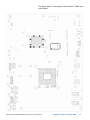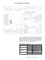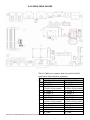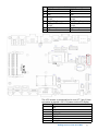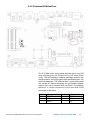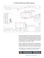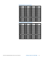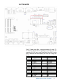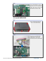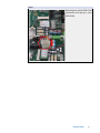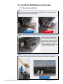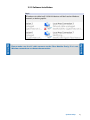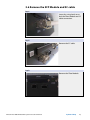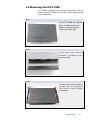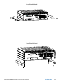
1
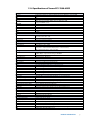
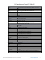
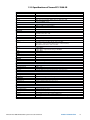
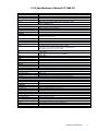
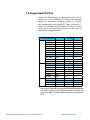
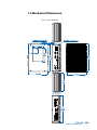
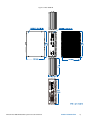
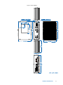
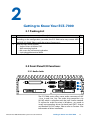
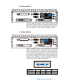
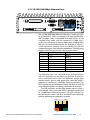
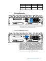
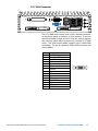
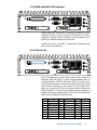
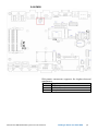
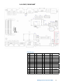
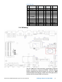
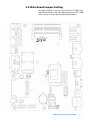
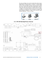
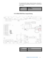
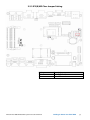
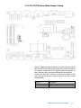
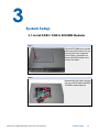
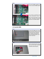
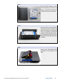
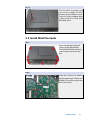
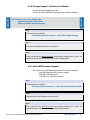
1.0.6 Edition 11/11/2015
All information is subject to change without notice.
Worldwide Technical Support and Product Information
www.vecow.com
Vecow Corporate Headquarters
12F No 111 Zhongcheng Rd Tucheng Dist New Taipei City 23674 Taiwan R.O.C.
Tel: 886 2 2268 5658
Fax: 886 2 2268 1658
For further support information, refer to the Technical Support and Professional Services
appendix. To comment on Vecow Co., Ltd. documentation, refer to the Vecow Co., Ltd.
web site at www.vecow.com.
© 2014 Vecow Co., Ltd. All rights reserved.
Record of Revision
Version
V1.00
V1.01
V1.02
V1.03
V1.04
V1.05
V1.06
Date
March 05, 2013
March 07, 2013
Oct 04, 2013
Nov 13, 2013
Nov 26, 2013
Oct 29, 2015
Nov 11, 2015
Page
All
P8
V, 2, 3, 12, 13
V, 4, 15, 29, 62-64
67
P35,36,51
70
Description
Preliminary Release
CPU List
ECS-7000-9GD & ECS-7000-9R
ECS-7000-6F Added
BIOS Revised
Update
Update
Remark
Declaimer
This manual is intended to be used as a practical and informative guide
only and is subject to change without prior notice. It does not represent
commitment from Vecow Co., Ltd. Vecow shall not be liable for direct, indirect,
special, incidental, or consequential damages arising out of the use of the
product or documentation, nor for any infringements upon the rights of third
parties, which may result from such use.
Declaration of Conformity
FCCThis equipment has been tested and found to comply with the limits for a
Class A digital device, pursuant to part 15 of the FCC Rules. These limits are
designed to provide reasonable protection against harmful interference when
the equipment is operated in a commercial environment. This equipment
generates, uses, and can radiate radio frequency energy and, if not installed
and used in accordance with the instruction manual, may cause harmful
interference to radio communications. Operation of this equipment in a
residential area is likely to cause harmful interference in which case the user will
be required to correct the interference at his own expense.
CE
The product(s) described in this manual complies with all applicable European
Union (CE) directives if it has a CE marking. For computer systems to remain CE
compliant, only CE-compliant parts may be used. Maintaining CE compliance
also requires proper cable and cabling techniques.
Copyright and Trademarks
This document contains proprietary information protected by copyright.
All rights are reserved. No part of this document may be reproduced by any
mechanical, electronic, or other means in any form without prior written
permission of the manufacturer. Company/product names mentioned herein
are used for identification
©Vecow ECS-7000 Embedded System Series User Manual
iv
Order Information
Part Number
ECS-7000-9GD
ECS-7000-9R
ECS-7000-6F
ECS-7000-6GDE
ECS-7000-6GD
ECS-7000-6R
ECS-7000-6G
ECS-7000-4G
ECS-7000-2R
ECS-7000-2G
Description
9 GbE LAN Fanless Embedded Controller, 2 HDD, Isolated DIO, SUMIT (A, B),
iAMT 8.0
9 GbE LAN Fanless Embedded Controller, 2 HDD, Isolated DIO, iAMT 8.0
6 GbE LAN for 4 Copper & 2 Fiber SFP Sockets Fanless Embedded Controller,
2 HDD
6 GbE LAN Fanless Embedded Controller, 2 HDD, Isolated DIO, SUMIT (A, B),
iAMT 8.0
6 GbE LAN Fanless Embedded Controller, 2 HDD, Isolated DIO, iAMT 8.0
6 GbE LAN Fanless Embedded Controller, 2 Front Panel Access Removable HDD
with Key Lock, iAMT 8.0
6 GbE LAN Fanless Embedded Controller, 2 HDD, iAMT 8.0
4 GbE LAN Fanless Embedded Controller, 2 HDD, iAMT 8.0
2 GbE LAN Fanless Embedded Controller, 2 Front Panel Access Removable HDD
with Key Lock
2 GbE LAN Fanless Embedded Controller, 2 HDD
Optional Accessories
Part Number
M340S-W28M1
KVR1333D3S9/4G
PWA-120WM4P
SCSI-20P-100
TMB-SCSI-20P
Description
Vecow DDR3 4GB 1333/1066MHz RAM, Wide Temperature -40°C ~ +85°C
Kingston® DDR3 4GB PC1333 RAM
120W, 24V, 90VAC to 264VAC power adapter
20-pin SCSI Cable, 1M
Terminal Board with One 20-pin SCSI Connector and DIN-Rail Mounting
v
Table of Contents
Declaimeriv
Declaration of Conformity
iv
Copyright and Trademarks
iv
FCCiv
CEiv
Order Information
Optional Accessories
v
v
General Introduction
1
1.1 Overview
1.2 Product Specification
1
2
1.2.1 Specifications of Vecow ECS-7000-9GD
1.2.2 Specifications of Vecow ECS-7000-9R
1.2.3 Specifications of Vecow ECS-7000-6F
1.2.4 Specifications of Vecow ECS-7000-6GDE
1.2.5 Specifications of Vecow ECS-7000-6GD
1.2.6 Specifications of Vecow ECS-7000-6R
1.2.7 Specifications of Vecow ECS-7000-6G
1.2.8 Specifications of Vecow ECS-7000-4G
1.2.9 Specifications of Vecow ECS-7000-2R
1.2.10 Specifications of Vecow ECS-7000-2G
2
3
4
5
6
7
8
9
10
11
1.3 Supported CPU List
1.4 Mechanical Dimension
12
13
Getting to Know Your ECS-7000
22
2.1 Packing List
2.2 Front Panel I/O Functions
22
22
2.2.1 Audio Jacks
2.2.2 Dual USB 3.0
2.2.3 Dual USB 2.0
2.2.4 10/100/1000 Mbps Ethernet Ports
2.2.5 Dual Display Port
2.2.6 DVI-D/HDMI Connector
2.2.7 VGA Connector
2.2.8 PWR and HDD LED Indicators
2.2.9 CFast Card
2.2.10 Power Button
2.2.11 Reset Tact Switch
2.2.12 SFP on ECS-7000-6F
22
23
23
24
25
25
26
27
27
28
28
29
2.3 Rear Panel I/O Functions
30
2.4 Main Board Expansion Connectors
35
2.3.1 DC-In 6~36V Mini DIN or Power Terminal Block 2.3.2 Remote Power On/Off Switch
2.3.3 Isolated 8 DI / 8 DO
2.3.4 Serial Port COM2
2.3.5 Serial Port COM1/COM3 / COM4
30
30
31
33
33
2.4.1 J1 Miscellaneous Pin Header
2.4.2 CN23, CN25, J4 LVDS
2.4.2 CN23, CN25, J4 LVDS
2.4.3 CN17, CN20 SATA3 & CN21 SATA Power Connector
2.4.4 CN13 SATA-II Connector J3 SATA DOM Power Connector
2.4.5 J2 Internal USB Dual Port
37
37
38
40
42
44
vi
2.4.6 CN8, CN14 Mini-PCIe, mSATA Connectors
2.4.7 CN16 GPIO
2.4.8 FAN1 2.4.9 CN27, CN28 SUMIT
2.4.10 Battery
45
47
48
49
50
2.5 Main Board Jumper Setting
51
2.5.1 JP3 LVDS Backlight Power Selection
2.5.2 JP2(A) CMOS Clear Jumper Setting
2.5.3 JP2(B) ME Clear Jumper Setting
2.5.4 JP1 AT/ATX Power Mode Jumper Setting
52
53
54
55
System Setup
56
3.1 Install DDR3 / DDR3L SODIMM Modules
3.2 Install HDD
3.3 Install MiniPCIe Cards
3.4 Install SATA DOM
3.5 Install the SFP Module and SC cable
56
57
59
60
62
3.5.1 Hardware Installation
3.5.2 Software Installation
62
63
3.6 Remove the SFP Module and SC cable
3.6 Mounting Your ECS-7000
64
65
BIOS and Driver
67
4.1 BIOS Settings
67
4.1.1 Main Menu
4.1.2 Advanced Function
4.1.3 Chipset Function
4.1.4 Boot Function
68
68
73
74
4.2 Operating System
4.3 Driver Installation
74
75
4.3.1 Chipset Driver Installation
4.3.2 Intel HD 4000 Graphics Driver Installation
4.3.3 Network Device Driver Installation
4.3.4 Audio Driver Installation
4.3.5 USB 3.0 Driver Installation
4.3.6 Storage Support Software Installation
4.3.7 Intel AMT Function Support
75
76
76
77
77
78
78
Appendix A : Isolating DIO Guide
79
Appendix B : GPIO & WDT Function
81
A. Entry MB PnP Mode
B. Located on Logical Device 7
C. Access the Super I/O Register
D. Start to Access the ECS-7000 GPIO Port
E. WDT ON/OFF and Timer-Counter setting
81
81
81
81
82
G
1
General Introduction
1.1 Overview
ECS-7000 series support 3 rd Gen Intel® Core™ series
processor (6M Cache, up to 3.30 GHz), DDR3L and DDR3
maximum dual channel 16GB ram, 3 independent display
(DP, DVI-D, and VGA), isolated DIO, maximum 9 GbE LANs,
CFast, two 2.5” SATA 6Gp/s HDD/SSD trays, 4 COM, 4 USB
3.0 ports, JST connector, and 2 miniPCI-express, plus with
overvoltage protection and Trusted Platform Module
which making ECS-7000 series stand out from others in
machine vision and GigE imaging, intelligent automation,
sur veillance and security, and most of embedded
applications.
ECS-7000 full series powered by cutting-edge the 3rd Gen
Intel® Quad-Core™i7 Processor (6M Cache, up to 3.3 GHz)
not only increasing power efficiency as much as 25% also
integrates Intel® HD 4000 graphics and extremely low
thermal design power as 35W providing an enhanced
reliability, safety and shock resistance for fanless operation
required environments.
Maximum 9 GbE LAN, ECS-7000 series provide stable and
speedy Ethernet with 9.6 kb/s to 1 Gb/s data transmission
option for high bandwidth and supports Ethernet Control
Automation Technology (EtherCAT).
Product Introduction
1
1.2 Product Specification
1.2.1 Specifications of Vecow ECS-7000-9GD
System
Processor
Chipset
BIOS
SIO
Memory
3rd Generation Intel® Core™ i7/i5/i3 Ivy Bridge Processors (6M Cache, up to 3.30 GHz)
Intel® QM77
AMI
IT8783F
DDR3 1066/1333/1600 MHz, DDR3L 1066/1333 MHz, Max. 16GB, 2 204-pin SO-DIMM Sockets
I/O Ports
Serial Interface
USB
Isolated DIO
LED
GPIO
3 COM RS-232, 1 COM RS-232 / 485 / 422
4 USB 3.0, 2 USB 2.0, 2 Internal USB 2.0
8 DI, 8 DO
Power, HDD and CFast LEDs
16 GPIO
Expansion
Mini PCIe
JST Connector
1 miniPCIe Socket: PCIe + USB + SIM Card Socket, 1 miniPCIe Socket: PCIe + USB
1 Internal 6-pin (Internal USB 2.0)
Graphics
Chipset
Display Memory
Interface
Intel® GMA HD 4000
Shared Memory, Up to 1.7GB
DB-15 VGA / 1920 x 1200 Max., DVI-D / 1920 x 1200 Max.,
Display Port 1 / 2560 x 1600 Max., Display Port 2 / 1920 x 1200 Max.,
LVDS / Dual Channel 24-bit / 1920 x 1200 Max.
Storage
SATA
2 SATA III 6Gbps, 1 SATA II 3Gbps - Support Horizontal Type SATA DOM
mSATA
Storage Expansion
2 SATA II 3Gbps
CFast Slot Push In / Out Ejector
Audio
Audio Codec
Audio Interface
Realtek ALC892, 5.1 Channel HD Audio
Line-in, Line-out, Mic-in, Front Audio Header
Ethernet
LAN1
LAN2
LAN3
LAN4
LAN5
LAN6
LAN7
LAN8
LAN9
Intel® 82579LM Gigabit LAN, Wake on LAN, PXE Support
Intel® 82574L Gigabit LAN, Wake on LAN, PXE Support
Intel® 82574L Gigabit LAN, Wake on LAN, PXE Support
Intel® 82574L Gigabit LAN, Wake on LAN, PXE Support
Intel® 82574L Gigabit LAN, Wake on LAN, PXE Support
Intel® 82574L Gigabit LAN, Wake on LAN, PXE Support
Intel® 82574L Gigabit LAN, Wake on LAN, PXE Support
Intel® 82574L Gigabit LAN, Wake on LAN, PXE Support
Intel® 82574L Gigabit LAN, Wake on LAN, PXE Support
Power
Power Input
Power Input Voltage
Power Adapter
Protection
1 Mini DIN, One 3-pin Terminal Block for DC-IN : V+, V-, Frame Ground
DC-IN 6 ~ 36V
AC to DC +24V / 5A 120W Max. (Optional)
On-board LT4356 for Power Input High Voltage Surge Protection
Other
Trusted Platform Module (TPM)
Watchdog Timer
HW Monitor
Infineon SLB9635, LPC interface (Optional)
Reset: 1 to 255 sec / min Per Step
Temperature / Voltages Auto Throttling Control When CPU Overheats
Mechanical
Chasis Construction
Size (W x D x H)
Weight
Mounting
Aluminum Housing
260mm x 175mm x 79mm (10.2" x 6.9" x 3.1")
2.8 Kg (6 lb)
Wall-mount by Mounting Bracket
Environmental
Operating Temperature
Storage Temperature
-25°C to 70°C (-13°F to 157°F)
-40°C to 85°C (-40°F to 185°F)
Humidity
Relative Humidity
Vibration
Shock
EMC
10% to 95% Humidity, Non-condensing
95% at 70°C
Rational: 5Grms @5~500 Hz according to IEC68-2-64
Operating, 50 Grms, Half-sine 11 ms Duration (w / SSD, According to IEC60068-2-27)
CE, FCC, RoHS, EN50155 & EN50121-3-2
©Vecow ECS-7000 Embedded System Series User Manual
Product Introduction
2
1.2.2 Specifications of Vecow ECS-7000-9R
System
Processor
Chipset
BIOS
SIO
Memory
3rd Generation Intel® Core™ i7/i5/i3 Ivy Bridge Processors (6M Cache, up to 3.30 GHz)
Intel® QM77
AMI
IT8783F
DDR3 1066/1333/1600 MHz, DDR3L 1066/1333 MHz, Max. 16GB, 2 204-pin SO-DIMM Sockets
I/O Ports
Serial Interface
USB
LED
GPIO
3 COM RS-232, 1 COM RS-232 / 485 / 422
4 USB 3.0, 2 USB 2.0, 2 Internal USB 2.0
Power, HDD and CFast LEDs
16 GPIO
Expansion
Mini PCIe
JST Connector
1 miniPCIe Socket: PCIe + USB + SIM Card Socket, 1 miniPCIe Socket: PCIe + USB
1 Internal 6-pin (Internal USB 2.0)
Graphics
Chipset
Display Memory
Interface
Intel® GMA HD 4000
Shared Memory, Up to 1.7GB
DB-15 VGA / 1920 x 1200 Max., DVI-D / 1920 x 1200 Max.,
Display Port 1 / 2560 x 1600 Max., Display Port 2 / 1920 x 1200 Max.,
LVDS / Dual Channel 24-bit / 1920 x 1200 Max.
Storage
SATA
mSATA
Storage Expansion
2 SATA III 6Gbps, 1 SATA II 3Gbps - Support Horizontal Type SATA DOM
2 SATA II 3Gbps
CFast Slot Push In / Out Ejector
Audio
Audio Codec
Audio Interface
Realtek ALC892, 5.1 Channel HD Audio
Line-in, Line-out, Mic-in, Front Audio Header
Ethernet
LAN1
LAN2
LAN3
LAN4
LAN5
LAN6
LAN7
LAN8
LAN9
Intel® 82579LM Gigabit LAN, Wake on LAN, PXE Support
Intel® 82574L Gigabit LAN, Wake on LAN, PXE Support
Intel® 82574L Gigabit LAN, Wake on LAN, PXE Support
Intel® 82574L Gigabit LAN, Wake on LAN, PXE Support
Intel® 82574L Gigabit LAN, Wake on LAN, PXE Support
Intel® 82574L Gigabit LAN, Wake on LAN, PXE Support
Intel® 82574L Gigabit LAN, Wake on LAN, PXE Support
Intel® 82574L Gigabit LAN, Wake on LAN, PXE Support
Intel® 82574L Gigabit LAN, Wake on LAN, PXE Support
Power
Power Input
Power Input Voltage
Power Adapter
Protection
1 Mini DIN, One 3-pin Terminal Block for DC-IN : V+, V-, Frame Ground
DC-IN 6 ~ 36V
AC to DC +24V / 5A 120W Max. (Optional)
On-board LT4356 for Power Input High Voltage Surge Protection
Other
Trusted Platform Module (TPM)
Watchdog Timer
HW Monitor
Infineon SLB9635, LPC interface (Optional)
Reset: 1 to 255 sec / min Per Step
Temperature / Voltages Auto Throttling Control When CPU Overheats
Mechanical
Chasis Construction
Size (W x D x H)
Weight
Mounting
Aluminum Housing
260mm x 175mm x 79mm (10.2" x 6.9" x 3.1")
2.8 Kg (6 lb)
Wall-mount by Mounting Bracket
Environmental
Operating Temperature
Storage Temperature
-25°C to 70°C (-13°F to 157°F)
-40°C to 85°C (-40°F to 185°F)
Humidity
Relative Humidity
Vibration
Shock
EMC
10% to 95% Humidity, Non-condensing
95% at 70°C
Rational: 5Grms @5~500 Hz according to IEC68-2-64
Operating, 50 Grms, Half-sine 11 ms Duration (w / SSD, According to IEC60068-2-27)
CE, FCC, RoHS, EN50155 & EN50121-3-2
Product Introduction
3
1.2.3 Specifications of Vecow ECS-7000-6F
System
Processor
Chipset
BIOS
SIO
Memory
3rd Generation Intel® Core™ i7/i5/i3 Ivy Bridge Processors (6M Cache, up to 3.30 GHz)
Intel® QM77
AMI
IT8783F
DDR3 1066/1333/1600 MHz, DDR3L 1066/1333 MHz, Max. 16GB
2 204-pin SO-DIMM Sockets
I/O Ports
Serial Interface
USB
LED
GPIO
3 COM RS-232, 1 COM RS-232 / 485 / 422
4 USB 3.0, 2 USB 2.0, 2 Internal USB 2.0
Power, HDD and CFast LEDs
16 GPIO
Expansion
Mini PCIe
JST Connector
1 miniPCIe Socket: PCIe + USB + SIM Card Socket
1 miniPCIe Socket: PCIe + USB
1 Internal 6-pin (Internal USB 2.0)
Graphics
Chipset
Display Memory
Interface
Intel® GMA HD 4000
Shared Memory, Up to 1.7GB
DB-15 VGA / 1920 x 1200 Max., DVI-D / 1920 x 1200 Max.,
Display Port 1 / 2560 x 1600 Max., Display Port 2 / 1920 x 1200 Max.,
LVDS / Dual Channel 24-bit / 1920 x 1200 Max.
Storage
SATA
mSATA
Storage Expansion
2 SATA III 6Gbps
1 SATA II 3Gbps - Support Horizontal Type SATA DOM
2 SATA II 3Gbps
CFast Slot Push In / Out Ejector
Audio
Audio Codec
Audio Interface
Realtek ALC892, 5.1 Channel HD Audio
Line-in, Line-out, Mic-in, Front Audio Header
Ethernet
LAN1
LAN2
LAN3
LAN4
Fiber SPF
Fiber SPF
Intel® 82579LM Gigabit LAN, Wake on LAN, PXE Support
Intel® 82574L Gigabit LAN, Wake on LAN, PXE Support
Intel® 82574L Gigabit LAN, Wake on LAN, PXE Support
Intel® 82574L Gigabit LAN, Wake on LAN, PXE Support
1000Base SFP Port Based On Intel® I350 Chipset
1000Base SFP Port Based On Intel® I350 Chipset
Power
Power Input
Power Input Voltage
Power Adapter
Protection
1 Mini DIN, One 3-pin Terminal Block for DC-IN : V+, V-, Frame Ground
DC-IN 6 ~ 36V
AC to DC +24V / 5A 120W Max. (Optional)
On-board LT4356 for Power Input High Voltage Surge Protection
Other
Trusted Platform Module (TPM)
Watchdog Timer
HW Monitor
Infineon SLB9635, LPC interface (Optional)
Reset: 1 to 255 sec / min Per Step
Temperature / Voltages Auto Throttling Control When CPU Overheats
Mechanical
Chasis Construction
Size (W x D x H)
Weight
Mounting
Aluminum Housing
260mm x 175mm x 79mm (10.2" x 6.9" x 3.1")
2.8 Kg (6 lb)
Wall-mount by Mounting Bracket
Environmental
Operating Temperature
Storage Temperature
-25°C to 70°C (-13°F to 157°F)
-40°C to 85°C (-40°F to 185°F)
Humidity
Relative Humidity
Vibration
10% to 95% Humidity, Non-condensing
95% at 70°C
Rational: 5Grms @5~500 Hz according to IEC68-2-64
Shock
EMC
Operating, 50 Grms, Half-sine 11 ms Duration (w / SSD, According to IEC60068-2-27)
CE, FCC, RoHS, EN50155 & EN50121-3-2
4
1.2.4 Specifications of Vecow ECS-7000-6GDE
System
Processor
Chipset
BIOS
SIO
Memory
3rd Generation Intel® Core™ i7/i5/i3 Ivy Bridge Processors (6M Cache, up to 3.30 GHz)
Intel® QM77
AMI
IT8783F
DDR3 1066/1333/1600 MHz, DDR3L 1066/1333 MHz, Max. 16GB
2 204-pin SO-DIMM Sockets
I/O Ports
Serial Interface
USB
Isolated DIO
LED
GPIO
3 COM RS-232, 1 COM RS-232 / 485 / 422
4 USB 3.0, 2 USB 2.0, 2 Internal USB 2.0
8 DI, 8 DO
Power, HDD and CFast LEDs
16 GPIO
Expansion
Mini PCIe
SUMIT A, B
JST Connector
1 miniPCIe Socket: PCIe + USB + SIM Card Socket
1 miniPCIe Socket: PCIe + USB
2 SUMIT Slots
1 Internal 6-pin (Internal USB 2.0)
Graphics
Chipset
Display Memory
Interface
Intel® GMA HD 4000
Shared Memory, Up to 1.7GB
DB-15 VGA / 1920 x 1200 Max., DVI-D / 1920 x 1200 Max.,
Display Port 1 / 2560 x 1600 Max., Display Port 2 / 1920 x 1200 Max.,
LVDS / Dual Channel 24-bit / 1920 x 1200 Max.
Storage
SATA
mSATA
Storage Expansion
2 SATA III 6Gbps
1 SATA II 3Gbps - Support Horizontal Type SATA DOM
2 SATA II 3Gbps
CFast Slot Push In / Out Ejector
Audio
Audio Codec
Audio Interface
Realtek ALC892, 5.1 Channel HD Audio
Line-in, Line-out, Mic-in, Front Audio Header
Ethernet
LAN1
LAN2
LAN3
LAN4
LAN5
LAN6
Intel® 82579LM Gigabit LAN, Wake on LAN, PXE Support
Intel® 82574L Gigabit LAN, Wake on LAN, PXE Support
Intel® 82574L Gigabit LAN, Wake on LAN, PXE Support
Intel® 82574L Gigabit LAN, Wake on LAN, PXE Support
Intel® 82574L Gigabit LAN, Wake on LAN, PXE Support
Intel® 82574L Gigabit LAN, Wake on LAN, PXE Support
Power
Power Input
Power Input Voltage
Power Adapter
Protection
1 Mini DIN, One 3-pin Terminal Block for DC-IN : V+, V-, Frame Ground
DC-IN 6 ~ 36V
AC to DC +24V / 5A 120W Max. (Optional)
On-board LT4356 for Power Input High Voltage Surge Protection
Other
Trusted Platform Module (TPM)
Watchdog Timer
HW Monitor
Infineon SLB9635, LPC interface (Optional)
Reset: 1 to 255 sec / min Per Step
Temperature / Voltages Auto Throttling Control When CPU Overheats
Mechanical
Chasis Construction
Size (W x D x H)
Weight
Mounting
Aluminum Housing
260mm x 175mm x 79mm (10.2" x 6.9" x 3.1")
2.8 Kg (6 lb)
Wall-mount by Mounting Bracket
Environmental
Operating Temperature
Storage Temperature
-25°C to 70°C (-13°F to 157°F)
-40°C to 85°C (-40°F to 185°F)
Humidity
Relative Humidity
Vibration
10% to 95% Humidity, Non-condensing
95% at 70°C
Rational: 5Grms @5~500 Hz according to IEC68-2-64
Shock
EMC
Operating, 50 Grms, Half-sine 11 ms Duration (w / SSD, According to IEC60068-2-27)
CE, FCC, RoHS, EN50155 & EN50121-3-2
Product Introduction
5
1.2.5 Specifications of Vecow ECS-7000-6GD
System
Processor
Chipset
BIOS
SIO
Memory
3rd Generation Intel® Core™ i7/i5/i3 Ivy Bridge Processors (6M Cache, up to 3.30 GHz)
Intel® QM77
AMI
IT8783F
DDR3 1066/1333/1600 MHz, DDR3L 1066/1333 MHz, Max. 16GB
2 204-pin SO-DIMM Sockets
I/O Ports
Serial Interface
USB
Isolated DIO
LED
GPIO
3 COM RS-232, 1 COM RS-232 / 485 / 422
4 USB 3.0, 2 USB 2.0, 2 Internal USB 2.0
8 DI, 8 DO
Power, HDD and CFast LEDs
16 GPIO
Expansion
Mini PCIe
JST Connector
1 miniPCIe Socket: PCIe + USB + SIM Card Socket, 1 miniPCIe Socket: PCIe + USB
1 Internal 6-pin (Internal USB 2.0)
Graphics
Chipset
Display Memory
Interface
Intel® GMA HD 4000
Shared Memory, Up to 1.7GB
DB-15 VGA / 1920 x 1200 Max., DVI-D / 1920 x 1200 Max.,
Display Port 1 / 2560 x 1600 Max., Display Port 2 / 1920 x 1200 Max.,
LVDS / Dual Channel 24-bit / 1920 x 1200 Max.
Storage
SATA
mSATA
Storage Expansion
2 SATA III 6Gbps, 1 SATA II 3Gbps - Support Horizontal Type SATA DOM
2 SATA II 3Gbps
CFast Slot Push In / Out Ejector
Audio
Audio Codec
Audio Interface
Realtek ALC892, 5.1 Channel HD Audio
Line-in, Line-out, Mic-in, Front Audio Header
Ethernet
LAN1
LAN2
LAN3
LAN4
LAN5
LAN6
Intel® 82579LM Gigabit LAN, Wake on LAN, PXE Support
Intel® 82574L Gigabit LAN, Wake on LAN, PXE Support
Intel® 82574L Gigabit LAN, Wake on LAN, PXE Support
Intel® 82574L Gigabit LAN, Wake on LAN, PXE Support
Intel® 82574L Gigabit LAN, Wake on LAN, PXE Support
Intel® 82574L Gigabit LAN, Wake on LAN, PXE Support
Power
Power Input
Power Input Voltage
Power Adapter
Protection
1 Mini DIN, One 3-pin Terminal Block for DC-IN : V+, V-, Frame Ground
DC-IN 6 ~ 36V
AC to DC +24V / 5A 120W Max. (Optional)
On-board LT4356 for Power Input High Voltage Surge Protection
Other
Trusted Platform Module (TPM)
Watchdog Timer
HW Monitor
Infineon SLB9635, LPC interface (Optional)
Reset: 1 to 255 sec / min Per Step
Temperature / Voltages Auto Throttling Control When CPU Overheats
Mechanical
Chasis Construction
Size (W x D x H)
Weight
Mounting
Aluminum Housing
260mm x 175mm x 79mm (10.2" x 6.9" x 3.1")
2.8 Kg (6 lb)
Wall-mount by Mounting Bracket
Environmental
Operating Temperature
Storage Temperature
-25°C to 70°C (-13°F to 157°F)
-40°C to 85°C (-40°F to 185°F)
Humidity
Relative Humidity
Vibration
Shock
EMC
10% to 95% Humidity, Non-condensing
95% at 70°C
Rational: 5Grms @5~500 Hz according to IEC68-2-64
Operating, 50 Grms, Half-sine 11 ms Duration (w / SSD, According to IEC60068-2-27)
CE, FCC, RoHS, EN50155 & EN50121-3-2
©Vecow ECS-7000 Embedded System Series User Manual
Product Introduction
6
1.2.6 Specifications of Vecow ECS-7000-6R
System
Processor
Chipset
BIOS
SIO
Memory
3rd Generation Intel® Core™ i7/i5/i3 Ivy Bridge Processors (6M Cache, up to 3.30 GHz)
Intel® QM77
AMI
IT8783F
DDR3 1066/1333/1600 MHz, DDR3L 1066/1333 MHz, Max. 16GB
2 204-pin SO-DIMM Sockets
I/O Ports
Serial Interface
USB
LED
GPIO
3 COM RS-232, 1 COM RS-232 / 485 / 422
4 USB 3.0, 2 USB 2.0, 2 Internal USB 2.0
Power, HDD and CFast LEDs
16 GPIO
Expansion
Mini PCIe
JST Connector
1 miniPCIe Socket: PCIe + USB + SIM Card Socket, 1 miniPCIe Socket: PCIe + USB
1 Internal 6-pin (Internal USB 2.0)
Graphics
Chipset
Display Memory
Interface
Intel® GMA HD 4000
Shared Memory, Up to 1.7GB
DB-15 VGA / 1920 x 1200 Max., DVI-D / 1920 x 1200 Max.,
Display Port 1 / 2560 x 1600 Max., Display Port 2 / 1920 x 1200 Max.,
LVDS / Dual Channel 24-bit / 1920 x 1200 Max.
Storage
SATA
mSATA
Storage Expansion
2 SATA III 6Gbps, 1 SATA II 3Gbps - Support Horizontal Type SATA DOM
2 SATA II 3Gbps
CFast Slot Push In / Out Ejector
Audio
Audio Codec
Audio Interface
Realtek ALC892, 5.1 Channel HD Audio
Line-in, Line-out, Mic-in, Front Audio Header
Ethernet
LAN1
LAN2
LAN3
LAN4
LAN5
LAN6
Intel® 82579LM Gigabit LAN, Wake on LAN, PXE Support
Intel® 82574L Gigabit LAN, Wake on LAN, PXE Support
Intel® 82574L Gigabit LAN, Wake on LAN, PXE Support
Intel® 82574L Gigabit LAN, Wake on LAN, PXE Support
Intel® 82574L Gigabit LAN, Wake on LAN, PXE Support
Intel® 82574L Gigabit LAN, Wake on LAN, PXE Support
Power
Power Input
Power Input Voltage
Power Adapter
Protection
1 Mini DIN, One 3-pin Terminal Block for DC-IN : V+, V-, Frame Ground
DC-IN 6 ~ 36V
AC to DC +24V / 5A 120W Max. (Optional)
On-board LT4356 for Power Input High Voltage Surge Protection
Other
Trusted Platform Module (TPM)
Watchdog Timer
HW Monitor
Infineon SLB9635, LPC interface (Optional)
Reset: 1 to 255 sec / min Per Step
Temperature / Voltages Auto Throttling Control When CPU Overheats
Mechanical
Chasis Construction
Size (W x D x H)
Weight
Mounting
Aluminum Housing
260mm x 175mm x 79mm (10.2" x 6.9" x 3.1")
2.8 Kg (6 lb)
Wall-mount by Mounting Bracket
Environmental
Operating Temperature
Storage Temperature
-25°C to 70°C (-13°F to 157°F)
-40°C to 85°C (-40°F to 185°F)
Humidity
Relative Humidity
Vibration
Shock
EMC
10% to 95% Humidity, Non-condensing
95% at 70°C
Rational: 5Grms @5~500 Hz according to IEC68-2-64
Operating, 50 Grms, Half-sine 11 ms Duration (w / SSD, According to IEC60068-2-27)
CE, FCC, RoHS, EN50155 & EN50121-3-2
Product Introduction
7
1.2.7 Specifications of Vecow ECS-7000-6G
System
Processor
Chipset
BIOS
SIO
Memory
3rd Generation Intel® Core™ i7/i5/i3 Ivy Bridge Processors (6M Cache, up to 3.30 GHz)
Intel® QM77
AMI
IT8783F
DDR3 1066/1333/1600 MHz, DDR3L 1066/1333 MHz, Max. 16GB
2 204-pin SO-DIMM Sockets
I/O Ports
Serial Interface
USB
LED
GPIO
3 COM RS-232, 1 COM RS-232 / 485 / 422
4 USB 3.0, 2 USB 2.0, 2 Internal USB 2.0
Power, HDD and CFast LEDs
16 GPIO
Expansion
Mini PCIe
JST Connector
1 miniPCIe Socket: PCIe + USB + SIM Card Socket, 1 miniPCIe Socket: PCIe + USB
1 Internal 6-pin (Internal USB 2.0)
Graphics
Chipset
Display Memory
Interface
Intel® GMA HD 4000
Shared Memory, Up to 1.7GB
DB-15 VGA / 1920 x 1200 Max., DVI-D / 1920 x 1200 Max.,
Display Port 1 / 2560 x 1600 Max., Display Port 2 / 1920 x 1200 Max.,
LVDS / Dual Channel 24-bit / 1920 x 1200 Max.
Storage
SATA
mSATA
Storage Expansion
2 SATA III 6Gbps, 1 SATA II 3Gbps - Support Horizontal Type SATA DOM
2 SATA II 3Gbps
CFast Slot Push In / Out Ejector
Audio
Audio Codec
Audio Interface
Realtek ALC892, 5.1 Channel HD Audio
Line-in, Line-out, Mic-in, Front Audio Header
Ethernet
LAN1
LAN2
LAN3
LAN4
LAN5
LAN6
Intel® 82579LM Gigabit LAN, Wake on LAN, PXE Support
Intel® 82574L Gigabit LAN, Wake on LAN, PXE Support
Intel® 82574L Gigabit LAN, Wake on LAN, PXE Support
Intel® 82574L Gigabit LAN, Wake on LAN, PXE Support
Intel® 82574L Gigabit LAN, Wake on LAN, PXE Support
Intel® 82574L Gigabit LAN, Wake on LAN, PXE Support
Power
Power Input
Power Input Voltage
Power Adapter
Protection
1 Mini DIN, One 3-pin Terminal Block for DC-IN : V+, V-, Frame Ground
DC-IN 6 ~ 36V
AC to DC +24V / 5A 120W Max. (Optional)
On-board LT4356 for Power Input High Voltage Surge Protection
Other
Trusted Platform Module (TPM)
Watchdog Timer
HW Monitor
Infineon SLB9635, LPC interface (Optional)
Reset: 1 to 255 sec / min Per Step
Temperature / Voltages Auto Throttling Control When CPU Overheats
Mechanical
Chasis Construction
Size (W x D x H)
Weight
Mounting
Aluminum Housing
260mm x 175mm x 79mm (10.2" x 6.9" x 3.1")
2.8 Kg (6 lb)
Wall-mount by Mounting Bracket
Environmental
Operating Temperature
Storage Temperature
-25°C to 70°C (-13°F to 157°F)
-40°C to 85°C (-40°F to 185°F)
Humidity
Relative Humidity
Vibration
Shock
EMC
10% to 95% Humidity, Non-condensing
95% at 70°C
Rational: 5Grms @5~500 Hz according to IEC68-2-64
Operating, 50 Grms, Half-sine 11 ms Duration (w / SSD, According to IEC60068-2-27)
CE, FCC, RoHS, EN50155 & EN50121-3-2
©Vecow ECS-7000 Embedded System Series User Manual
Product Introduction
8
1.2.8 Specifications of Vecow ECS-7000-4G
System
Processor
Chipset
BIOS
SIO
Memory
3rd Generation Intel® Core™ i7/i5/i3 Ivy Bridge Processors (6M Cache, up to 3.30 GHz)
Intel® QM77
AMI
IT8783F
DDR3 1066/1333/1600 MHz, DDR3L 1066/1333 MHz, Max. 16GB
2 204-pin SO-DIMM Sockets
I/O Ports
Serial Interface
USB
LED
GPIO
3 COM RS-232, 1 COM RS-232 / 485 / 422
4 USB 3.0, 2 USB 2.0, 2 Internal USB 2.0
Power, HDD and CFast LEDs
16 GPIO
Expansion
Mini PCIe
JST Connector
1 miniPCIe Socket: PCIe + USB + SIM Card Socket
1 miniPCIe Socket: PCIe + USB
1 Internal 6-pin (Internal USB 2.0)
Graphics
Chipset
Display Memory
Interface
Intel® GMA HD 4000
Shared Memory, Up to 1.7GB
DB-15 VGA / 1920 x 1200 Max., DVI-D / 1920 x 1200 Max.,
Display Port 1 / 2560 x 1600 Max., Display Port 2 / 1920 x 1200 Max.,
LVDS / Dual Channel 24-bit / 1920 x 1200 Max.
Storage
SATA
mSATA
Storage Expansion
2 SATA III 6Gbps
1 SATA II 3Gbps - Support Horizontal Type SATA DOM
2 SATA II 3Gbps
CFast Slot Push In / Out Ejector
Audio
Audio Codec
Audio Interface
Realtek ALC892, 5.1 Channel HD Audio
Line-in, Line-out, Mic-in, Front Audio Header
Ethernet
LAN1
LAN2
LAN3
LAN4
Intel® 82579LM Gigabit LAN, Wake on LAN, PXE Support
Intel® 82574L Gigabit LAN, Wake on LAN, PXE Support
Intel® 82574L Gigabit LAN, Wake on LAN, PXE Support
Intel® 82574L Gigabit LAN, Wake on LAN, PXE Support
Power
Power Input
Power Input Voltage
Power Adapter
Protection
1 Mini DIN, One 3-pin Terminal Block for DC-IN : V+, V-, Frame Ground
DC-IN 6 ~ 36V
AC to DC +24V / 5A 120W Max. (Optional)
On-board LT4356 for Power Input High Voltage Surge Protection
Other
Trusted Platform Module (TPM)
Watchdog Timer
HW Monitor
Infineon SLB9635, LPC interface (Optional)
Reset: 1 to 255 sec / min Per Step
Temperature / Voltages Auto Throttling Control When CPU Overheats
Mechanical
Chasis Construction
Size (W x D x H)
Weight
Mounting
Aluminum Housing
260mm x 175mm x 79mm (10.2" x 6.9" x 3.1")
2.8 Kg (6 lb)
Wall-mount by Mounting Bracket
Environmental
Operating Temperature
Storage Temperature
-25°C to 70°C (-13°F to 157°F)
-40°C to 85°C (-40°F to 185°F)
Humidity
Relative Humidity
Vibration
Shock
EMC
10% to 95% Humidity, Non-condensing
95% at 70°C
Rational: 5Grms @5~500 Hz according to IEC68-2-64
Operating, 50 Grms, Half-sine 11 ms Duration (w / SSD, According to IEC60068-2-27)
CE, FCC, RoHS, EN50155 & EN50121-3-2
Product Introduction
9
1.2.9 Specifications of Vecow ECS-7000-2R
System
Processor
Chipset
BIOS
SIO
Memory
3rd Generation Intel® Core™ i7/i5/i3 Ivy Bridge Processors (6M Cache, up to 3.30 GHz)
Intel® QM77
AMI
IT8783F
DDR3 1066/1333/1600 MHz, DDR3L 1066/1333 MHz, Max. 16GB
2 204-pin SO-DIMM Sockets
I/O Ports
Serial Interface
USB
LED
GPIO
3 COM RS-232, 1 COM RS-232 / 485 / 422
4 USB 3.0, 2 USB 2.0, 2 Internal USB 2.0
Power, HDD and CFast LEDs
16 GPIO
Expansion
Mini PCIe
JST Connector
1 miniPCIe Socket: PCIe + USB + SIM Card Socket
1 miniPCIe Socket: PCIe + USB
1 Internal 6-pin (Internal USB 2.0)
Graphics
Chipset
Display Memory
Interface
Intel® GMA HD 4000
Shared Memory, Up to 1.7GB
DB-15 VGA / 1920 x 1200 Max., DVI-D / 1920 x 1200 Max.,
Display Port 1 / 2560 x 1600 Max., Display Port 2 / 1920 x 1200 Max.,
LVDS / Dual Channel 24-bit / 1920 x 1200 Max.
Storage
SATA
mSATA
Storage Expansion
2 SATA III 6Gbps
1 SATA II 3Gbps - Support Horizontal Type SATA DOM
2 SATA II 3Gbps
CFast Slot Push In / Out Ejector
Audio
Audio Codec
Audio Interface
Realtek ALC892, 5.1 Channel HD Audio
Line-in, Line-out, Mic-in, Front Audio Header
Ethernet
LAN1
LAN2
Intel® 82579LM Gigabit LAN, Wake on LAN, PXE Support
Intel® 82574L Gigabit LAN, Wake on LAN, PXE Support
Power
Power Input
Power Input Voltage
Power Adapter
Protection
1 Mini DIN, One 3-pin Terminal Block for DC-IN : V+, V-, Frame Ground
DC-IN 6 ~ 36V
AC to DC +24V / 5A 120W Max. (Optional)
On-board LT4356 for Power Input High Voltage Surge Protection
Other
Trusted Platform Module (TPM)
Watchdog Timer
HW Monitor
Infineon SLB9635, LPC interface (Optional)
Reset: 1 to 255 sec / min Per Step
Temperature / Voltages Auto Throttling Control When CPU Overheats
Mechanical
Chasis Construction
Size (W x D x H)
Weight
Mounting
Aluminum Housing
260mm x 175mm x 79mm (10.2" x 6.9" x 3.1")
2.8 Kg (6 lb)
Wall-mount by Mounting Bracket
Environmental
Operating Temperature
Storage Temperature
-25°C to 70°C (-13°F to 157°F)
-40°C to 85°C (-40°F to 185°F)
Humidity
Relative Humidity
Vibration
Shock
EMC
10% to 95% Humidity, Non-condensing
95% at 70°C
Rational: 5Grms @5~500 Hz according to IEC68-2-64
Operating, 50 Grms, Half-sine 11 ms Duration (w / SSD, According to IEC60068-2-27)
CE, FCC, RoHS, EN50155 & EN50121-3-2
©Vecow ECS-7000 Embedded System Series User Manual
Product Introduction
10
1.2.10 Specifications of Vecow ECS-7000-2G
System
Processor
Chipset
BIOS
SIO
Memory
3rd Generation Intel® Core™ i7/i5/i3 Ivy Bridge Processors (6M Cache, up to 3.30 GHz)
Intel® QM77
AMI
IT8783F
DDR3 1066/1333/1600 MHz, DDR3L 1066/1333 MHz, Max. 16GB
2 204-pin SO-DIMM Sockets
I/O Ports
Serial Interface
USB
LED
GPIO
3 COM RS-232, 1 COM RS-232 / 485 / 422
4 USB 3.0, 2 USB 2.0, 2 Internal USB 2.0
Power, HDD and CFast LEDs
16 GPIO
Expansion
Mini PCIe
JST Connector
1 miniPCIe Socket: PCIe + USB + SIM Card Socket
1 miniPCIe Socket: PCIe + USB
1 Internal 6-pin (Internal USB 2.0)
Graphics
Chipset
Display Memory
Interface
Intel® GMA HD 4000
Shared Memory, Up to 1.7GB
DB-15 VGA / 1920 x 1200 Max., DVI-D / 1920 x 1200 Max.,
Display Port 1 / 2560 x 1600 Max., Display Port 2 / 1920 x 1200 Max.,
LVDS / Dual Channel 24-bit / 1920 x 1200 Max.
Storage
SATA
mSATA
Storage Expansion
2 SATA III 6Gbps
1 SATA II 3Gbps - Support Horizontal Type SATA DOM
2 SATA II 3Gbps
CFast Slot Push In / Out Ejector
Audio
Audio Codec
Audio Interface
Realtek ALC892, 5.1 Channel HD Audio
Line-in, Line-out, Mic-in, Front Audio Header
Ethernet
LAN1
LAN2
Intel® 82579LM Gigabit LAN, Wake on LAN, PXE Support
Intel® 82574L Gigabit LAN, Wake on LAN, PXE Support
Power
Power Input
Power Input Voltage
Power Adapter
Protection
1 Mini DIN, One 3-pin Terminal Block for DC-IN : V+, V-, Frame Ground
DC-IN 6 ~ 36V
AC to DC +24V / 5A 120W Max. (Optional)
On-board LT4356 for Power Input High Voltage Surge Protection
Other
Trusted Platform Module (TPM)
Watchdog Timer
HW Monitor
Infineon SLB9635, LPC interface (Optional)
Reset: 1 to 255 sec / min Per Step
Temperature / Voltages Auto Throttling Control When CPU Overheats
Mechanical
Chasis Construction
Size (W x D x H)
Weight
Mounting
Aluminum Housing
260mm x 175mm x 79mm (10.2" x 6.9" x 3.1")
2.8 Kg (6 lb)
Wall-mount by Mounting Bracket
Environmental
Operating Temperature
Storage Temperature
-25°C to 70°C (-13°F to 157°F)
-40°C to 85°C (-40°F to 185°F)
Humidity
Relative Humidity
Vibration
Shock
EMC
10% to 95% Humidity, Non-condensing
95% at 70°C
Rational: 5Grms @5~500 Hz according to IEC68-2-64
Operating, 50 Grms, Half-sine 11 ms Duration (w / SSD, According to IEC60068-2-27)
CE, FCC, RoHS, EN50155 & EN50121-3-2
Product Introduction
11
1.3 Supported CPU List
Vecow ECS-7000 accepts 3rd generation Intel® i7/i5/i3
processors via a rPGA988B CPU socket. The following
processors have been tested by Vecow Co., Ltd. for
the compatibility with Vecow ECS-7000. Instead of i73610QE, i5-3610ME and i3-3120ME, You may also select
other processor according to your consideration of
application and performance.
Series
i7
i5
i3
3840QM
3820QM
3740QM
3720QM
3632QM
3630QM
3612QM
3610QE
3610QM
3540M
3520M
3610ME
3380M
3360M
3340M
3320M
3230M
3210M
3130M*
3120ME
3120M*
3110M*
Max. TDP iAMT
45W
√
45W
√
45W
√
45W
√
35W
45W
35W
45W
√
45W
35W
√
35W
√
35W
√
35W
√
35W
√
35W
√
35W
√
35W
35W
35W
35W
35W
35W
Embedded
O
O
O
The processors with "O" are listed in Intel® Embedded Roadmap
and with a 7-year life cycle support (from 2011 to 2017). The
processors with "* " the maximum operation temperature is
55OC.
©Vecow ECS-7000 Embedded System Series User Manual
Product Introduction
12
1.4 Mechanical Dimension
Figure 1.1 ECS-7000-9GD
Product Introduction
13
Figure 1.2 ECS-7000-9R
©Vecow ECS-7000 Embedded System Series User Manual
Product Introduction
14
Figure 1.3 ECS-7000-6F
Product Introduction
15
Figure 1.4 ECS-7000-6GDE / ECS-7000-6GD
©Vecow ECS-7000 Embedded System Series User Manual
Product Introduction
16
Figure 1.5 ECS-7000-6R
Product Introduction
17
Figure 1.6 ECS-7000-6G
©Vecow ECS-7000 Embedded System Series User Manual
Getting to Know Your ECS-7000
18
Figure 1.7 ECS-7000-4G
Getting to Know Your ECS-7000
19
Figure 1.8 ECS-7000-2R
©Vecow ECS-7000 Embedded System Series User Manual
Getting to Know Your ECS-7000
20
Figure 1.9 ECS-7000-2G
Getting to Know Your ECS-7000
21
2
Getting to Know Your ECS-7000
2.1 Packing List
Item
Description
Qty
1 ECS-7000 Series fanless controller
1
(According to the configuration you order, the ECS-7000 series may contain HDD
and DDR3 SO-DIMM. Please verify these items if necessary.)
2 Accessory box, which contains
1
• Vecow Drivers & Utilities DVD
• Wall-mounting bracket
2
• M4 screws for wall-mounting bracket
4
• 4-pin pluggable terminal block
2
2.2 Front Panel I/O Functions
2.2.1 Audio Jacks
Reset
CFast
HDD
DVI-D
PWR
VGA
2
LAN2
LAN1
1
The ECS-7000 series offers stereo audio connector of MIC
, Line_In and Line_Out. The audio chip controller is by
ALC892 which is compliant with the Intel® Azalia standard.
To utilize the audio function in Windows, you need to
install corresponding drivers for both Intel QM77 chipset
and Realtek ALC892 codec. Please refer to Section 4 for
information of driver installation.
©Vecow ECS-7000 Embedded System Series User Manual
Getting to Know Your ECS-7000
22
2.2.2 Dual USB 3.0
Reset
CFast
HDD
DVI-D
PWR
VGA
LAN2
2
LAN1
1
The ECS-7000 series comes with 2 USB 3.0 hosts on the
front panel. These USB 3.0 ports allow data transfers up to 5
Gb/s. The controller supports SuperSpeed (SS), high-speed
(HS), full-speed (FS) and los-speed (LS) traffic on the bus.
2.2.3 Dual USB 2.0
Reset
CFast
HDD
DVI-D
PWR
VGA
LAN2
2
LAN1
1
The ECS-7000 series comes with 2 USB 2.0 hosts on the front
panel. The USB interface supports Plug and Play, which
enables you to connect or disconnect a device whenever
you want, without turning off the system. The hosts can
be used for an external flash disk or hard drive for storing
large amounts of data. You can also use these USB hosts to
connect to a keyboard or a mouse. The following diagram
shows the pinouts for USB1 and USB2 port.
1
Pin Number
USB1
USB2
1
+5V
+5V
2
2
USB1USB2-
3
4
3
USB1+
USB2+
4
GND
GND
Getting to Know Your ECS-7000
23
2.2.4 10/100/1000 Mbps Ethernet Ports
Reset
CFast
HDD
DVI-D
PWR
VGA
LAN2
2
LAN1
1
The 10/100/1000 Mbps Ethernet LAN ports 1 and 2 use 8-pin
RJ-45 connector. LAN1 is equipped with Intel 82579LM for
AMT function. LAN2 is equipped with Intel 82574L. Using
suitable RJ-45 cable, you can connect ECS-7000 sereis
system to a computer, or to any other piece of equipment
that has an Ethernet connection, for example, a hub or a
switch. Moreover, both of them have Wake-on-LAN and
Preboot Execution Environment capabilities. The following
diagram shows the pinouts for LAN1 and LAN2 port.
Pin No. 10 / 100 Mbps
1000 Mbps
1
E_TX+
MDI0_P
2
E_TXMDI0_N
3
E_RX+
MDI1_P
4
---MDI2_P
5
----MDI2_N
6
E_RXMDI1_N
7
----MDI3_P
8
-----MDI3_N
The Ethernet ports use standard RJ-45 jack connectors
with LED indicators on the front side to show Active/Link
status and Speed status. The LED indicators on the right
bottom corners glow a solid green color when the cable is
properly connected to a 100 Mbps Ethernet network. The
LED indicator on the left bottom corner will flash on and off
when Ethernet packets are being transmitted or received.
The LED indicators on the right bottom corners glow a
solid orange color when the cable is properly connected
to a 1000 Mbps Ethernet network. The LED indicator on
the left bottom corner will flash on and off when Ethernet
packets are being transmitted or received.
1
©Vecow ECS-7000 Embedded System Series User Manual
8
Getting to Know Your ECS-7000
24
Location
10 Mbps
Right Bottom
off
LED
Left Bottom Flash Yellow
LED
100 Mbps
Solid Green
1000 Mbps
Solid Orange
Flash Yellow
Flash Yellow
2.2.5 Dual Display Port
Reset
CFast
HDD
DVI-D
PWR
VGA
2
LAN2
LAN1
1
Each digital port is capable of driving resolutions up to
2560x1600 at 60 Hz through Display Port.
2.2.6 DVI-D/HDMI Connector
Reset
CFast
HDD
DVI-D
PWR
VGA
2
LAN2
LAN1
1
The DVI-D connector on the front panel supports both
DVI and HDMI operation mode. This connector can either
output DVI signals or HDMI signal. The DVI output mode
supports up to 1920x1200 resolutions and HDMI output
mode supports up to 1920x1200 resolutions. The DVI or
HDMI mode is automatically selected according to the
display device connected. You shall need a DVI-D to HDMI
cable when connecting to a HDMI display device.
Getting to Know Your ECS-7000
25
2.2.7 VGA Connector
Reset
CFast
HDD
DVI-D
PWR
VGA
2
LAN2
LAN1
1
The ECS-7000 series comes with a DB15 female connector
on the front panel to connect a VGA monitor. To ensure
that the monitor image remains clear, be sure to tighten
the monitor cable after connecting it to the ECS-7000
series . The VGA output mode supports up to 1920x1200
resolutions. The pin assignments of the VGA connector are
shown below.
Pin No.
1
2
3
4
5
6
7
8
9
10
11
12
13
14
15
©Vecow ECS-7000 Embedded System Series User Manual
Description
Red Color Signal
Green Color Signal
Blue Color Signal
NC
Ground
VGA Detect
Ground
Ground
VCC
Ground
NC
DDC-DATA
H-Sync.
V-Sync.
DDC-CLK
5
10
15
Getting to Know Your ECS-7000
1
6
11
26
2.2.8 PWR and HDD LED Indicators
Reset
CFast
HDD
DVI-D
PWR
VGA
2
LAN2
LAN1
1
Yellow-HDD LED: A hard disk / CFast LED. If the LED is on, it
indicates that the system’s storage is functional. If it is off, it
indicates that the system’s storage is not functional. If it is
flashing, it indicates data access activities.
Green-Power LED: If the LED is solid green, it indicates that
the system is powered on.
2.2.9 CFast Card
Reset
CFast
HDD
DVI-D
PWR
VGA
2
LAN2
LAN1
1
The ECS-7000 series system comes with a CFast socket on
the front panel for Type-I / Type-II Compact Flash card. It is
implemented by a SATA II Port from QM77 PCH. Be sure to
disconnect the power source and unscrew the CFast socket
cover before installing a CFast card. The ECS-7000 series
does not support the CFast hot swap and PnP (Plug and
Play) functions. It is necessary to remove power source first
before inserting or removing the CFast card. The following
table shows the pinouts for CFast port:
Pin No.
S1
S2
S3
S4
S5
S6
S7
PC1
Description
GND
SATA_TX_P2
SATA_TX_N2
GND
SATA_RX_N2
SATA_RX_P2
GND
NC
Pin No. Description
PC2
GND
PC3
NC
PC4
NC
PC5
NC
PC6
NC
PC7
GND
PC8
NC
CFAST_LED_N
PC9
Pin No. Description
PC10 NC
PC11 NC
PC12 NC
PC13 +3.3V
PC14 +3.3V
PC15 GND
PC16 GND
PC17 NC
Getting to Know Your ECS-7000
27
2.2.10 Power Button
Reset
CFast
HDD
DVI-D
PWR
VGA
2
LAN2
LAN1
1
The power button is a non-latched switch with dual color
LED (Blue/Orange) for indication S0, S3 and S5 status. Power
button dual-color LED indicator:
Status LED Display System Situation
S0
Solid Blue
System working
S3, S5 Solid Orange Suspend to RAM, System off with
standby power
To turn on the ECS-7000 series, press the power button
and the blue LED is lighted up. To turn off the ECS-7000
series, you can either issue a shutdown command in OS, or
just simply press the power button.
In case of system halts, you can press and hold the power
button for 4 seconds to compulsorily shut down the system.
Please note that a 4 seconds interval is kept by the system
between two on/off operations (i.e. once turning off the
system, you shall wait for 4 seconds to initiate another
power-on operation).
2.2.11 Reset Tact Switch
Reset
CFast
HDD
DVI-D
PWR
VGA
2
LAN2
LAN1
1
It is a hardware reset switch. Use this switch to reset
the system without turning off the power. Momentarily
pressing the switch will activate a reset.
©Vecow ECS-7000 Embedded System Series User Manual
Getting to Know Your ECS-7000
28
2.2.12 SFP on ECS-7000-6F
Reset
CFast
HDD
DVI-D
PWR
VGA
2
LAN2
LAN1
1
The SFP modules are input/output devices that plug
into a Gigabit Ethernet (GE) port, linking the port with a
1000BASE-X fiber-optic network.
The SFP Modules are hot-swappable input/output (I/
O) devices that plug into the sockets, which connect the
module port with the fiber-optic.
You can use any combination of SFP modules as long as
each port must match the wavelength specifications on the
other end of the cable and the cable must not exceed the
stipulated cable length for reliable communications.
Getting to Know Your ECS-7000
29
2.3 Rear Panel I/O Functions
2.3.1 DC-In 6~36V Mini DIN or Power Terminal Block
LAN3
LAN6
COM2
COM4
COM1
COM3
Isolated DIO
+
LAN5
(+)
LAN4
On / Off
Power Switch
The ECS-7000 series offers 6 to 36 VDC power input with the
terminal block. If the power is supplied properly, the Power
LED will light up a solid green.
80V power surge protection is design in in LTC4356.
Grounding and write routing help limit the effects of noise
due to EMI. Run the ground connection from the ground
screw to the grounding surface prior to connecting the
power.
See the figure shown below for the location of the earth
ground on the terminal block power connector. Connect
the earth ground wire to an appropriate grounded metal
surface.
DC 6-36V
2.3.2 Remote Power On/Off Switch
LAN3
LAN6
COM2
COM4
COM1
COM3
LAN5
Isolated DIO
+
(+)
LAN4
On / Off
Power Switch
It is a 2-pin power-on or power-off switch through Phoenix
Contact terminal block. You could turn on or off the system
power by using this contact. This terminal block support
dual function of soft power-on / power-off (instant off or
delay 4 second), and suspend mode.
©Vecow ECS-7000 Embedded System Series User Manual
Getting to Know Your ECS-7000
30
2.3.3 Isolated 8 DI / 8 DO
LAN3
LAN6
COM2
COM4
COM1
COM3
Isolated DIO
+
LAN5
(+)
LAN4
On / Off
Power Switch
The ECS-7000 series offers an 16-bit DIO ( 8-DI / 8-DO)
connector. Each bit of DI and DO equipped with a photocoupler for isolated protection. A power buffer device
TPD2007F integrated in 8-DO circuit for motors, solenoids,
and lamp drivers applications.
Pin No. Definition
1
2
3
4
5
6
7
8
9
10
11
12
13
14
15
16
17
18
19
20
INPUT0
INPUT 1
INPUT 2
INPUT 3
INPUT 4
INPUT 5
INPUT 6
INPUT 7
DI_COM
GND
OUTPUT0
OUTPUT 1
OUTPUT 2
OUTPUT 3
OUTPUT 4
OUTPUT 5
OUTPUT 6
OUTPUT 7
N.C.
External 24VDC Input
Mapping to SIO GPIO
Function
SIO_GPI50
SIO_GPI51
SIO_GPI52
SIO_GPI53
SIO_GPI54
SIO_GPI55
SIO_GPI56
SIO_GPI57
SIO_GPO20
SIO_GPO21
SIO_GPO22
SIO_GPO23
SIO_GPO24
SIO_GPO25
SIO_GPO26
SIO_GPO27
Getting to Know Your ECS-7000
31
GPI SINK Mode
Isolated GPI input circuit in SINK mode (NPN) is illustrated as
follows.
GPI SOURCE Mode
Digital GPI input signal circuit in SOURCE mode (PNP) is
illustrated as follow:
GPO SINK Mode:
Digital GPO output circuit in SINK mode (NPN) is illustrated
below.
©Vecow ECS-7000 Embedded System Series User Manual
Getting to Know Your ECS-7000
32
2.3.4 Serial Port COM2
LAN3
LAN6
COM2
COM4
COM1
COM3
Isolated DIO
+
LAN5
(+)
LAN4
On / Off
Power Switch
Serial port 2 can be configured for RS-232, RS-422, or RS485 with auto flow control communication. Serial Port 2
default setting is RS-232, if you want to use RS-422 or RS485, you can find the setting in BIOS.
BIOS Setting
COM2
Function
RS-232
RS-422 (5-wire)
RS-422 (9-wire)
RS-485
RS-485 w/z auto-flow control
The pin assignments are shown in the following table:
Serial
Pin No. RS-232 RS-422 RS-422 RS-485
Port
(5-Wire) (9-Wire) (3-Wire)
1
DCD
TXDTXDDATA2
RXD
TXD+
TXD+
DATA+
3
TXD
RXD+
RXD+
----------4
DTR
RXDRXD----------2
5
GND
GND
GND
GND
6
DSR
----------- RTS----------7
RTS
----------- RTS+
----------8
CTS
----------- CTS+
----------9
RI
----------- CTS-----------
2.3.5 Serial Port COM1/COM3 / COM4
LAN3
LAN6
LAN5
COM2
COM4
COM1
COM3
Isolated DIO
+
(+)
LAN4
On / Off
Power Switch
Getting to Know Your ECS-7000
33
COM1, COM3 and COM4 are RS-232 only and provide up to
115200 bps baud rates. The pin assignments are shown in
the following table:
BIOS Setting
Pin No.
Function
1
DCD
2
RXD
3
TXD
4
DTR
COM1, 3, 4
5
GND
6
DSR
7
RTS
8
CTS
9
RI
©Vecow ECS-7000 Embedded System Series User Manual
Getting to Know Your ECS-7000
34
2.4 Main Board Expansion Connectors
The figure below is the top view of the ECS-7000 series
main board. It shows the location of the connectors.
Figure 2.3.1 Internal Connectors and Jumpers
Getting to Know Your ECS-7000
35
The figure below is the bottom view of the ECS-7000 series
main board.
©Vecow ECS-7000 Embedded System Series User Manual
Getting to Know Your ECS-7000
36
2.4.1 J1 Miscellaneous Pin Header
These pin headers can be used as a backup for the following
functions: hard drive LED indicator, reset button, power LED
indicator, and power-on/off button. The front and top panel
already provides access to these functions. The following
table shows the pinouts for Miscellaneous port
J5 Miscellaneous Pin Header
Group
Pin No.
HDD LED
1
3
Reset Button
5
7
Power
2
LED
4
Power Button
6
8
Description
HDLED
HD_LED_N
FP_RST_BTN_N
GND
PWRLED
PWROK_100MS_N
FP_PWR_BTN_N
GND
2.4.2 CN23, CN25, J4 LVDS
These pin headers can be used as a backup for the following
functions: hard drive LED indicator, reset button, power LED
indicator, and power-on/off button. The front and top panel
already provides access to these functions. The following
table shows the pinouts for Miscellaneous port:
J1 Miscellaneous Pin Header
Group
Pin No.
HDD LED
1
3
Reset Button
5
7
Power LED
2
4
Power Button
6
8
Description
HDLED
HD_LED_N
FP_RST_BTN_N
GND
PWRLED
PWROK_100MS_N
FP_PWR_BTN_N
GND
Getting to Know Your ECS-7000
37
2.4.2 CN23, CN25, J4 LVDS
The ECS-7000 series supports dual-channel 24-bit LVDS
panel up to 1366x768 pixels resolution.
Definition
Pin
No. CN23 Channel A
CN25 Channel B
1
LDDC_CLK
LDDC_CLK
2
LDDC_DATA
LDDC_DATA
3
PANEL_VDD
PANEL_VDD
(+3.3V or +5V by jumper) (+3.3V or +5V by jumper)
4
LA_ DATA0_P
LB_ DATA0_P
5
LA_ DATA3_P
LB_ DATA3_P
6
LA_ DATA0_N
LB_ DATA0_N
7
LA_ DATA3_N
LB_ DATA3_N
8
PANEL_VDD
PANEL_VDD
(+3.3V or +5V by jumper) (+3.3V or +5V by jumper)
9
GND
GND
10 LA_ DATA1_P
LB_ DATA1_P
11 LA_ CLKP
LB_ CLKP
12 LA_ DATA1_N
LB_ DATA1_N
13 LA_ CLKN
LB_ CLKN
©Vecow ECS-7000 Embedded System Series User Manual
Getting to Know Your ECS-7000
38
Pin
No.
14
15
16
17
18
19
20
CN23 Channel A
GND
GND
PANEL_BACKLIGHT
(+12V)
LA_ DATA2_P
PANEL_BACKLIGHT
(+12V)
LA_ DATA2_N
GND
Definition
CN25 Channel B
GND
GND
PA N E L _ B A C K L I G H T
(+12V)
LB_ DATA2_P
PA N E L _ B A C K L I G H T
(+12V)
LB_ DATA2_N
GND
The LCD inverter is connected to J4 via a JST 7-pin, 2.5mm
connector to provide +5V/+12V power to the LCD display.
Pin No.
Definition
1
+5V
2
+12V
3
+12V
4
LBKLT_CTL
5
GND
6
GND
7
LBKLT_EN
Getting to Know Your ECS-7000
39
2.4.3 CN17, CN20 SATA3 & CN21 SATA Power Connector
The ECS-7000 series features 2 high performance Serial ATA
III interfaces that ease cabling to hard drives or SSD with
thin and short cables while application need larger storage
capacity.
Pin No.
Definition
1
GND
2
TXP
3
TXN
4
GND
5
RXN
6
RXP
7
GND
©Vecow ECS-7000 Embedded System Series User Manual
Getting to Know Your ECS-7000
40
The ECS-7000 series is also equipped one SATA power
connector. It supplies 5V (2A max.) and 12V (1A max)
current to the hard drive or SSD.
CN21 SATA HDD Power Connections
Pin No.
Definition
1
+12V
2
GND
3
GND
4
+5V
Getting to Know Your ECS-7000
41
2.4.4 CN13 SATA-II Connector J3 SATA DOM Power Connector
The ECS-7000 series features one SATA-II interface while
applications need SATA DOM.
Pin No.
1
2
3
4
5
6
7
©Vecow ECS-7000 Embedded System Series User Manual
Definition
GND
TXP
TXN
GND
RXN
RXP
GND
Getting to Know Your ECS-7000
42
The ECS-7000 series is also equipped one SATA DOM power
connector. It supplies 5V (0.5A max.) current to the SATA
DOM.
J3 SATA DOM Power Connections
Pin No.
Definition
1
+5V
2
GND
Getting to Know Your ECS-7000
43
2.4.5 J2 Internal USB Dual Port
The ECS-7000 series’ main board provides up to two USB
plug-and-play ports for Dongle Key or LCD touch Panel
using. The USB interface supports 480 Mbps transfer rate
which complies with high speed USB specification Rev. 2.0,
and fuse protection. The USB interface is accessed through
one 1x6-pin JST 2.0mm connector. You will need an adapter
cable if you use a standard USB connector. The adapter
cable has a 1x6-pin connector on one end and a USB
connector on the other.
Pin No.
1
3
5
©Vecow ECS-7000 Embedded System Series User Manual
Definition
USB_VCC
USBD2+
USBD3+
Pin No.
2
4
6
Definition
USBD2USBD3GND
Getting to Know Your ECS-7000
44
2.4.6 CN8, CN14 Mini-PCIe, mSATA Connectors
Both mSATA and Mini PCI-E share the same form-factor and
similar electrical pinout assignments on their connectors.
There was no clear mechanism to distinguish if a mSATA
drive or a Mini PCI-E device is plugged into the socket until
recently that SATA-IO issued an ECN change (ECN #045)
to re-define pin 43 on mSATA connector as “no connect”
instead of “return current path” ( or GND).
When an mSATA drive is inserted, its pin 43 is “no connect”,
and the respective pin on the socket is being pulled-up
to logic 1. When a Mini PCI-E device is inserted, its pin 43
forces the respective pin on the socket to ground, or logic 0.
ECS-7000 series is using Pin 43 status designed for
switching between mSATA drive and mini PCI-e device.
Status
Pin 43
Mini PCI-e card
Logic 0
mSATA drive
Logic 1
Getting to Know Your ECS-7000
45
CN8 Mini-PCIe Connector Pin Out
Pin
No.
51
49
47
45
43
41
39
37
35
Signal
Name
Reserved
Reserved
Reserved
Reserved
Status
+3.3Vaux
+3.3Vaux
GND
GND
Pin
No.
52
50
48
46
44
42
40
38
36
15
13
11
9
GND
REFCLK+
REFCLKGND
16
14
12
10
Signal
Pin Signal
Name
No. Name
+3.3Vaux 33 PETp0
GND
31 PETn0
+1.5V
29 GND
Reserved 27 GND
Reserved 25 PERp0
Reserved 23 PERn0
GND
21 GND
USB_D+ 19 Reserved
USB_D17 Reserved
Mechanical Key
Reserved 7 CLKREQ#
Reserved 5 Reserved
Reserved 3 Reserved
Reserved 1 WAKE#
Pin Signal
No. Name
34 GND
32 SMB_DATA
30 SMB_CLK
28 +1.5V
26 GND
24 +3.3Vaux
22 PERST#
20 reserved
18 GND
8
6
4
2
Reserved
1.5V
GND
3.3Vaux
CN14 Mini-PCIe Connector Pin Out
Pin
No.
51
49
47
45
43
41
39
37
35
Signal
Name
Reserved
Reserved
Reserved
Reserved
Status
+3.3Vaux
+3.3Vaux
GND
GND
Pin
No.
52
50
48
46
44
42
40
38
36
15
13
11
9
GND
REFCLK+
REFCLKGND
16
14
12
10
©Vecow ECS-7000 Embedded System Series User Manual
Signal
Pin Signal
Name
No. Name
+3.3Vaux 33 PETp0
GND
31 PETn0
+1.5V
29 GND
Reserved 27 GND
Reserved 25 PERp0
Reserved 23 PERn0
GND
21 GND
USB_D+ 19 Reserved
USB_D17 Reserved
Mechanical Key
UIM_VPP 7 CLKREQ#
UIM_RST 5 Reserved
UIM_CLK 3 Reserved
UIM_DATA 1 WAKE#
Pin Signal
No. Name
34 GND
32 SMB_DATA
30 SMB_CLK
28 +1.5V
26 GND
24 +3.3Vaux
22 PERST#
20 reserved
18 GND
8
6
4
2
UIM_PWR
1.5V
GND
3.3Vaux
Getting to Know Your ECS-7000
46
2.4.7 CN16 GPIO
The ECS-7000 series offers 16 programmable I/O within TTL
5V tolerance. If the GPIO is logic high, it indicates that the
mapping SIO GPIO pin is logic high level. If the GPIO is logic
low, it indicates that the mapping SIO GPIO pin is logic low
level.
Pin No. Description
Pin No. Description
1
GND
14
GND
2
SIO_GP17
15
SIO_GP67
3
SIO_GP16
16
SIO_GP66
4
SIO_GP15
17
SIO_GP65
5
SIO_GP14
18
SIO_GP64
6
GND
19
GND
7
SIO_GP13
20
SIO_GP63
8
SIO_GP12
21
SIO_GP62
9
SIO_GP11
22
SIO_GP61
10
SIO_GP10
23
SIO_GP60
11
GND
24
GND
12
SMB_DATA
25
+5V
13
SMB_CLK
26
+5V
Getting to Know Your ECS-7000
47
2.4.8 FAN1
FAN power connector suppor ts for higher thermal
requirement.
Pin Out
Function
1
GND
2
+12V (1.5A max)
3
Fan-speed sense
©Vecow ECS-7000 Embedded System Series User Manual
Getting to Know Your ECS-7000
48
2.4.9 CN27, CN28 SUMIT
CN28 Pin out
Pin
Out
1
3
5
7
9
11
13
15
17
19
Function
+5V_AUX
+3.3V
+3.3V
Reserved
Reserved
USB_OC#
Reserved
+5V
USB_3+
USB_3-
21 +5V
23 USB_2+
25 USB_2-
Pin
Out
2
4
6
8
10
12
14
16
18
20
Function
Pin
Out
+12V
27
SMB_DATA 29
XMB_CLK 31
Reserved
33
SPI_MISO
35
SPI_MOSI
37
SPI_CLK
39
SPI_CS10
41
SPI_CS1#
43
Reserved
45
Function
Pin
Out
+5V
28
USB_1+
30
USB_132
+5V
34
USB_0+
36
USB_038
GND
40
A_PET_P0 42
A_PET_N0 44
GND
46
22 LPC_DRQ1# 47 PERST#
24 LPC_AD0
49 WAKE#
26 LPC_AD1
51 +5V
Function
LPC_AD2
LPC_AD3
LPC_FRAME#
SERIRQ#
Reserved
CLK_33MHz
GND
A_PER_P0
A_PER_N0
APRSNT#/A_
PE_CLKREQ#
48 A_CLKP
50 A_CLKN
52 GND
Getting to Know Your ECS-7000
49
CN27 Pin Out
Pin
Out
1
3
5
7
9
11
13
15
17
19
21
23
25
Function
GND
B_PET_P0
B_PET_N0
GND
C_CLKP
C_CLKN
CPRSNT#/C_
PE_CLKREQ#
C_PET_P0
C_PET_N0
GND
C_PET_P1
C_PET_N1
GND
Pin
Out
2
4
6
8
10
12
14
Function
Pin Function
Out
GND
27 C_PET_P2
B_PER_P0 29 C_PET_N2
B_PER_N0 31 GND
GND
33 C_PET_P3
B_CLKP
35 C_PET_N3
B_CLKN
37 GND
GND
39 PERST#
Pin
Out
28
30
32
34
36
38
40
Function
16
18
20
22
24
26
C_PER_P0
C_PER_N0
GND
C_PER_P1
C_PER_N1
GND
42
44
46
48
50
52
Reserved
Reserved
+3.3V
+3.3V
+3.3V
+5V_AUX
41
43
45
47
49
51
Reserved
+5V
+5V
+5V
+5V
+5V
C_PER_P2
C_PER_N2
GND
C_PER_P3
C_PER_N3
GND
WAKE#
2.4.10 Battery
The ECS-7000 series’ real-time clock is powered by a lithium
battery. The battery is Panasonic BR2032 190mAh lithium
battery. Replacing the lithium battery on your own is NOT
recommended. If the battery needs to be changed, please
contact with the Vecow RMA service team.
©Vecow ECS-7000 Embedded System Series User Manual
Getting to Know Your ECS-7000
50
2.5 Main Board Jumper Setting
The figure below is the top view of the ECS-7000 series
main board which is the main board used in the ECS-7000
Series system. It shows the location of the jumpers.
Getting to Know Your ECS-7000
51
You may configure your card to match the needs of your
application by setting jumpers. A jumper is a metal bridge
used to close an electric circuit. It consists of two metal
pins and a small metal clip (often protected by a plastic
cover) that slides over the pins to connect them. To “close”
a jumper, you connect the pins with the clip. To “open”
a jumper, you remove the clip. Sometimes a jumper will
have three pins, labeled 1, 2 and 3. In this case you would
connect either pins 1 and 2, or 2 and 3.
2.5.1 JP3 LVDS Backlight Power Selection
©Vecow ECS-7000 Embedded System Series User Manual
Getting to Know Your ECS-7000
52
JP1 provides LVDS voltage selection function, closing Pin 1,
2 is for 3.3V LVDS power input; closing Pin 2, 3 is for 5V LVDS
power input.
Setting
1-2
2-3
Description
+3.3V (Default)
+5V
2.5.2 JP2(A) CMOS Clear Jumper Setting
Setting
1-3
3-5
Description
Normal (Default)
Clear CMOS
Getting to Know Your ECS-7000
53
2.5.3 JP2(B) ME Clear Jumper Setting
Setting
2-4
4-6
©Vecow ECS-7000 Embedded System Series User Manual
Description
Normal (Default)
Clear ME
Getting to Know Your ECS-7000
54
2.5.4 JP1 AT/ATX Power Mode Jumper Setting
The ECS-7000 main board contains a jumper that can switch
the AT/ATX Power Setting. Normally this jumper should be
set with Pin 4 and Pin 6 in ATX power mode. And power on
the system by the 2-pin terminal block at the top panel.
If you set it with Pin 2 and Pin 4 in AT power mode. It will
send the power button signal to power on the system
automatically
Setting
1-2
2-3
Description
AT Mode
ATX Mode (Default)
Getting to Know Your ECS-7000
55
3
System Setup
3.1 Install DDR3 / DDR3L SODIMM Modules
Step1.
Put the ECS-7000 series upside
down on a flat surface. You can
see the “Pet-Door” exposed.
Use a Philips screwdriver to
loose the M3 flat-head screw
on the “Pet-Door”.
Step2.
Remove the “Pet-Door” and you
can see a SATA cable and DDR3
SODIMM socket exposed.
©Vecow ECS-7000 Embedded System Series User Manual
System Setup
56
Step3.
Tile the SODIMM module and
insert it to the SODIMM socket.
As it’s firmly contacted with
socket connectors, press it
down until the clamps of the
socket snap into the latching
position of SODIMM module.
3.2 Install HDD
Step1.
Put the ECS-7000 series upside
down on a flat surface. You can
see the “Pet-Door” exposed.
Use a Philips screwdriver to
loose the M3 flat-head screw
on the “Pet-Door”.
Step2.
Remove the “Pet-Door” and you
can see a SATA cable and DDR3
SODIMM socket exposed.
System Setup
57
Step3.
Find the HDD bracket come
with “Pet-Door”, M3 screws (4
pieces), and HDD thermal pad
(1 piece) in the accessory box.
Step4.
Place the HDD into the bracket
and gently push it down to
make it contact with thermal
pad. Use a Philips screwdriver
to fix the HDD with M3 screws.
Please note that the HDD must
be placed in the right direction
as below.
Step5.
Pull out the SATA cable inside
the chassis and connect it to
HDD.
SATA Connector of HDD
©Vecow ECS-7000 Embedded System Series User Manual
System Setup
58
Step 6.
Tilt the HDD assembly and
i n s e r t t h e we d g e o f H D D
bracket to the bottom cover.
Once it’s firmly wedged, push
it down and fix it using a M3
flat-head screw.
3.3 Install MiniPCIe Cards
Step1.
Use a screwdriver to loose 9
screws on the “Back Panel”.
Find the BH-M2.5X6 (4 pieces)
screws pack in the accessory
box.
Step2.
There are 2 Mini-PCIe sockets
on the main board. Choose one
of Mini-PCIe socket to put your
mini-PCIe card in.
System Setup
59
Step3.
Using 2 BH-M2.5X6 screws to
lock your mini-PCIe card firmly.
Then you can re -screw the
back panel as the first step.
3.4 Install SATA DOM
Step1.
Use a screwdriver to loose 9
screws on the “Back Panel”.
Step2.
Preparing your SATA DOM
and finding 3 SATA DOM
connectors on the main board.
©Vecow ECS-7000 Embedded System Series User Manual
System Setup
60
Step3.
Selecting one of the SATA DOM
connector and plug in your
SATA DOM.
System Setup
61
3.5 Install the SFP Module and SC cable
3.5.1 Hardware Installation
Step1.
Please make sure the swing latch of the SFP Module is in on the bottom
before you insert it to the SFP socket.
Correct
Wrong
Step2.
Pushing the Fiber module to
the socket till it locked to the
socket firmly. Repeat Step 2 if
you are inserting a second SFP
module. Do not remove the
SFP module plugs until you are
ready to install the cables.
Step3.
Inserting the SC cable to Fiber module, and you completes installation.
Complete
©Vecow ECS-7000 Embedded System Series User Manual
System Setup
62
3.5.2 Software Installation
Step1.
If hardware installed well, 2 i350 LAN devices will be listed on Windows
network, as below graphic:
System Setup
CAUTION!
CAUTION!
Please make sure the SC cable connects to the Fiber Module firmly, if it is not,
Windwos network can not detect the connection.
63
3.6 Remove the SFP Module and SC cable
Step1.
Loose the swing latch to unlock the Fiber Module and SC
cable connection.
Step2.
Remove the SC cable.
Step3.
Remove the Fiber Module.
©Vecow ECS-7000 Embedded System Series User Manual
System Setup
64
3.6 Mounting Your ECS-7000
ECS-7000 is shipped with wall-mount brackets. You can
mount your ECS-7000 series on the wall by following the
steps listed below.
Step1.
Put the ECS-7000 series upside
down on a flat surface. Use a
Philips screwdriver to loose
screw on the back side.
Step2.
Find your wall-mounts
b rac ket s (2 pieces)in th e
accessory box.
Step3.
Fix two wall-mount brackets
to the chassis with four
M4 screws using a Philips
screwdriver.
System Setup
65
Installation Method 1
Installation Method 2
©Vecow ECS-7000 Embedded System Series User Manual
System Setup
66
4
BIOS and Driver
4.1 BIOS Settings
The board uses UEFI BIOS that is use Serial Peripheral
Interface (SPI) Flash. The SPI Flash contains the BIOS Setup
program, POST, the PCI auto-configuration utility, LAN,
EEPROM information, and Serial port support. The BIOS setup
program is accessed by pressing the <Delete> key after the
Power-On Self-Test (POST) memory test begins and before
the operating system boot begins. The menu bar is shown
below.
Figure 4.1: BIOS Menu Bar
BIOS and Driver
67
4.1.1 Main Menu
Figure 4.2: BIOS Main Screen
System Time / Date : Press “TAB” key to switch sub-items of value .Then press “ +” key
or “-“ key number key for modify value.
4.1.2 Advanced Function
Figure 4.3: ACPI Setting Setup Screen
Enable ACPI Auto Configuration: This system support ACPI function as auto process.
You should Enable / Disable that depend as your O.S.
©Vecow ECS-7000 Embedded System Series User Manual
BIOS and Driver
68
Figure 4.4: Trusted Computing Setup Screen
Security Device Support : Enables or Disables BIOS support for security device.
O.S. will now show Security Device. TCG EFT protocol and INT1A interface will not be
available.
Current Status Information :
Show as below option
SUPPORT TURNED OFF
SUPPORT TURNED ON
Figure 4.5: Trusted Computing Setup Screen
Intel Virtualization Technology : For Virtualization Application or platform usage,
when enabled, a VMM can utilize the additional hardware capabilities provided by
Vanderpool Technology,
BIOS and Driver
69
Figure 4.6: SATA Configuration Setup Screen
SATA Controller(s) :
Enables or Disables integrate SATA controller for Storage device use.
SATA Mode Selection :
Determines how the SATA transfer mode for operate. Here have three option for
choice [IDE] / [AHCI] / [RAID]. For RAID operation, please contact our technical support
for detail information.
Serial Port 0~5 :
This system offers six SATA port for connection SATA device.
Advanced->IT8783F Super IO Configuration->Serial Port 1
Figure 4.7: Serial Port 1Setup Screen
Serial Port :
Enable or Disable Serial Port .
©Vecow ECS-7000 Embedded System Series User Manual
BIOS and Driver
70
Device Setting:
Current IO address and interrupt resource of Serial Port.
Change Settings :
Select another device setting .
Here have 4 option :
IO=3F8h; IRQ=4;
IO=2F8h; IRQ=3;
IO=3E8h; IRQ=10;
IO=2E8h; IRQ=11;
Advanced->IT8783F Super IO Configuration->Serial Port 2
Figure 4.8: Serial Port 2 Setup Screen
Serial Port :
Enable or Disable Serial Port .
Device Setting:
Current IO address and interrupt resource of Serial Port.
Change Settings :
Select another device setting .
Here have 4 option :
IO=3F8h; IRQ=4;
IO=2F8h; IRQ=3;
IO=3E8h; IRQ=10;
IO=2E8h; IRQ=11;
Interface Mode:
Here have 4 option :
RS-232 Mode
RS-422 Mode
RS-485 Mode
BIOS and Driver
71
Advanced->IT8783F Super IO Configuration->Serial Port 3
Figure 4.9: Serial Port 3 Setup Screen
Serial Port :
Enable or Disable Serial Port .
Device Setting:
Current IO address and interrupt resource of Serial Port.
Change Settings :
Select another device setting .
Here have 4 option :
IO=3F8h; IRQ=4;
IO=2F8h; IRQ=3;
IO=3E8h; IRQ=10;
IO=2E8h; IRQ=11;
IO=2F0h; IRQ=6;
IO=2E0h; IRQ=7;
Advanced->IT8783F Super IO Configuration->Serial Port 4
Figure 4.10: Serial Port 4 Setup Screen
Serial Port :
Enable or Disable Serial Port .
Device Setting:
Current IO address and interrupt resource of Serial Port.
©Vecow ECS-7000 Embedded System Series User Manual
BIOS and Driver
72
Change Settings :
Select another device setting .
Here have 4 option :
IO=3F8h; IRQ=4;
IO=2F8h; IRQ=3;
IO=3E8h; IRQ=10;
IO=2E8h; IRQ=11;
IO=2F0h; IRQ=6;
IO=2E0h; IRQ=7;
4.1.3 Chipset Function
Phoenix SecureCore(tm) Setup Utility
Main
Advanced
Chipset
Boot
Security
Save & Exit
WOL configuration
Chipset->PCH-IO Configuration->Wake on LAN
Figure 4.11: Network Setup Screen
PCH LAN Controller : Enable or Disable Serial Port .
Wake on LAN : Enable or Disable integrated LAN to wake the system.
This function also can active by O.S.
Power Loss Configuration
Chipset->PCH-IO Configuration->Restore AC Power Loss
Figure 4.12: Power Loss Setu Screen
BIOS and Driver
73
PCH LAN Controller :
[Power Off ] : When plug-in the power source , system will keep on SB mode.
[Power On ] : When plug-in the power source , system will auto booting .
[Last State ] : When plug-in the power source , system will keep on last power status.
4.1.4 Boot Function
Boot Option
Chipset->PCH-IO Configuration->Wake on LAN
Figure 4.13 Boot Setup Screen
Boot option : When you press “Enter” , you can select which device you would like to
boot.
4.2 Operating System
Linux :
Ubuntu 10.04LTS or Above
Fedora 13 or Above
And another Linux kernel 2.6.33 and RHL6.0
(* The Linux kernel of RHL , please check RadHat website first )
Windows :
Windows XP
Windows 7 Home/Professional/MediaCenter/
Windows 8 ( Do not support RT version)
Windows Server 2008 R2
Windows Server 2012
©Vecow ECS-7000 Embedded System Series User Manual
BIOS and Driver
74
4.3 Driver Installation
After you setup all hardware and firmware device, you should
install the correspond Software driver then active O.S process.
When you start to install the driver , please make sure you have
administrator ID for system authenticate.
Please follow below sequence for driver install
1. Intel Chipset
2. Intel HD 4000 Graphics
3. Network Device – Include 85574L and 82579LM
4. Audio Driver
5. USB 3.0 support
6. Storage: Include “ACHI” driver and Intel Rapid Storage
Software.
7. AMT function of Intel ME(Management Engine)
4.3.1 Chipset Driver Installation
This device software installs all components of ECS-7000 platform
chipset to the system target system. After install this software,
please ensure that as following features function properly:
1.
2.
3.
4.
PCIe / PCI . ISAPNP services config.
IDE/ACHI storage interface Support
USB Support
Identification of Intel Chipset Components in the Device
Manager.
Install instruction:
Step1.
Find the driver install file
• Windows 7 64bit version :
The Chipset driver location is : [CD]:\Win7\64bit\ChipsetDriver\
Step2.
Execute and install the files which matches your operation system.
Instruction windows will pop-up when you start to setup the driver,
please follow it and complete the setup processes.
Step3.
Once you completed the Intel Chipset Driver setup, please reboot your
system , all update function will be active on next time into Windows.
BIOS and Driver
75
4.3.2 Intel HD 4000 Graphics Driver Installation
This driver will install following features or function properly:
- Display serive
- High definition Audio support
Install instruction:
Step1.
Find the driver install file
• Windows 7 64bit version :
The Graphics driver location is : [CD]:\Win7\64bit\VGADriver\
Step2.
Execute and install the files. Instruction windows will pop-up when
you start to setup the driver, please follow it and complete the setup
processes.
Step3.
Once you completed the HD Graphics Driver Driver setup, please reboot
your system , all update function will be active on next time into Windows.
4.3.3 Network Device Driver Installation
This driver will install following features or function properly:
- LAN 1 : Intel 82579LM network device
- LAN 2~ LAN 6 : Intel 82574L network device.
( Please ensure your LAN port number)
Install instruction:
Step1.
Find the driver install file
• Windows 7 64bit version :
The network driver location is : [CD]:\Win7\64bit\LanDriver\
Step2.
Execute and install the files. Instruction windows will pop-up when
you start to setup the driver, please follow it and complete the setup
processes.
©Vecow ECS-7000 Embedded System Series User Manual
BIOS and Driver
76
Step3.
Once you finish the LAN device Driver setup , the LAN connection will loss
for a while and then restart automatically.
Step4.
If you need active AMT function as well , please refer to the section of “AMT
driver install”.
4.3.4 Audio Driver Installation
This driver will install Realtek High definition device software and
Utility.
Step1.
Find the driver install file
The Audio driver location is : [CD]:\Win7\64bit\Audio\
Step2.
Execute the install file and start to install it.
Step3.
Once you finish the Audio device Driver setup ,please reboot your system
, all update function will be active on next time into Windows.
4.3.5 USB 3.0 Driver Installation
This driver will install USB 3.0 device support software.
Step1.
Find the driver install file
USB 3.0 driver location is : [CD]:\Win7\64bit\USB3.0
Step2.
Execute the install file and start to install it.
Step3.
Once you finish the USB3.0 device Driver setup ,please reboot your system
, all update function will be active on next time into Windows.
BIOS and Driver
77
4.3.6 Storage Support Software Installation
Installing the Intel Rapid software
This driver will install following features or function properly:
CAUTION!
CAUTION!
This function only use on AHCI mode.
- Software panel for SATA device
- Utilities for RAID volume creating.
Step1.
Find the driver install file
Intel Rapid software location is : [CD]:\Win7\64bit\Storage
Step2.
Execute the install file and start to install it.
Step3.
Once you finish the Rapid software setup ,please reboot your system , all
update function will be active on next time into Windows.
4.3.7 Intel AMT Function Support
This driver will install following features or function properly:
- Intel ME (Management Engine) support
- Intel AMT software panel
- SOL(Serial on LAN) device driver .
Step1.
Find the driver install file
The Chipset driver location is : [CD]:\Win7\64bit\LanDriver\ME
Step2.
Execute the install file and start to install it.
Step3.
Once you finish the AMT function setup ,please reboot your system , all
update function will be active on next time into Windows.
©Vecow ECS-7000 Embedded System Series User Manual
BIOS and Driver
78
A
ppendix A : Isolating DIO Guide
Description:
Initialize hardware and resources, and get number of
functional borads.
Syntax:
I16 _mnet104_open ()
Argument:
Name
N/C
Return:
Return Value
ERR_NoError
Other
Type
Description
Description
The function finished execution successfully.
Please reference to the Appendix error table.
Description:
Get the local DI value.
Syntax:
I16 _mnet104_read_port( U16 Offset, U8 *Val )
Argument:
Name
Type Description
Offset
U16 Pointer the access DI port address
Val [output] U8 * Return the value of local input interface.
Return:
Return Value
ERR_NoError
Other
Description
The function finished execution successfully.
Please reference to the Appendix error table.
Description:
Get the local DI value.
Syntax:
I16 _mnet104_write_port( U16 Offset, U8 Val )
Argument:
Appendix A
79
Name
Offset
Val
Return:
Return Value
ERR_NoError
Other
©Vecow ECS-7000 Embedded System Series User Manual
Type Description
U16 Pointer the access DI port address
U8
Write the value of local input interface.
Description
The function finished execution successfully.
Please reference to the Appendix error table.
Appendix A
80
A
ppendix B : GPIO & WDT Function
The GPIO& WDT are using internal Super IO function.
However, you must entry super I/O configuration mode to set
it.
The output port is set as GPIO 1 on CN13 , reg. index = 0x60
The input port is set as GPIO 4 on CN12 , reg. index = 0x62.
Super I/O special address port = 0x2E
Super I/O special data port = 0x2F
GPIO Logical device is 0x07
A. Entry MB PnP Mode
//write twice 0x87 value.
outportb(Super I/O special address port, 0x87);
outportb(Super I/O special address port, 0x01);
outportb(Super I/O special address port, 0x55);
outportb(Super I/O special address port, 0x55);
B. Located on Logical Device 7
//write 0x07 on Reg [0x07] , this setup must follow Step A. that can be workable.
outportb(Super I/O special address port, 0x07);
outportb(Super I/O special data port, 0x07);
C. Access the Super I/O Register
Base control for write Super I/O register.
outportb(special address port, Register Index.);
outportb(special data port, update_value);
Base control for read Super I/O register
outportb(special address port, Register Index.);
inportb(special data port); //It will return a BYTE value.
D. Start to Access the ECS-7000 GPIO Port
Please refer to source code for set_data() and get_data() function.
Write data to GPO(output) port
set_data( Register Index , update_value);
example :
unsigned char data = 0x82;
set_data( 0xE5 , data);
//Set bit 7 & bit 1 of GPO output port as High level ,another bit is Low
Appendix B
81
Please refer to source code for set_data() and get_data() function.
Read data to GPI(input) port
get_data( Register Index ) //It will return a BYTE value.
example :
unsigned char data
get_data( 0xF1 , data);
//Get GPI(input) port status on input_data variable.
E. WDT ON/OFF and Timer-Counter setting
Refer to GPIO setting of Step A and B. , located Logical 0x08 for WDT function.
Reg [0x30] is WatchDog ON/OFF control.
WatchDog On : set_data( 0x30 , 0x01);
WatchDog Off : set_data( 0x30 , 0x00);
Reg [0xF0] is WatchDog timer - counterON/OFF control.
WatchDog counter start : set_data( 0xF0 , 0x02);
WatchDog counter start : set_data( 0xF0 , 0x00);
Reg [0xF1] is WatchDog time-out value, "Reading" this register returns the current
value in the Watch Dog Counter, not the Watch Dog Timer Time-out value..
WatchDog time-out value : set_data( 0xF1 , );
©Vecow ECS-7000 Embedded System Series User Manual
Appendix B
82