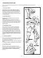
1
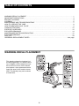
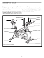
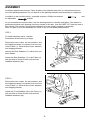
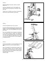
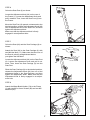
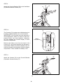
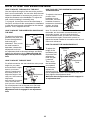
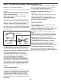
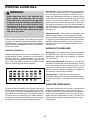
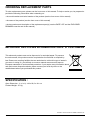
Model No. NTEVEX74612.1 Serial No. : ___________ USERʼS MANUAL Serial No Decal Write the serial number in the space above for reference. QUESTIONS ? If you have questions, or if there are missing parts, please contact us: UK Call: 08457 089 009 From Ireland: 053 92 36102 Website: www.iconsupport.eu E-mail: [email protected] Write: ICON Health & Fitness, Ltd. c/o HI Group PLC Express Way Whitwood, West Yorkshire WF10 5QJ UK CAUTION Read all precautions and instructions in this manual before using this equipment. Keep this manual for future reference. Visit our website www.iconsupport.eu TABLE OF CONTENTS WARNING DECAL PLACEMENT . . . . . . . . . . . . . . . . . . . . . . . . . . . . . . . . . . . . . . . . . . . . . . . . . . . . . . . . . . . . 1 IMPORTANT PRECAUTIONS . . . . . . . . . . . . . . . . . . . . . . . . . . . . . . . . . . . . . . . . . . . . . . . . . . . . . . . . . . . . . . . . . 3 BEFORE YOU BEGIN . . . . . . . . . . . . . . . . . . . . . . . . . . . . . . . . . . . . . . . . . . . . . . . . . . . . . . . . . . . . . . . . . . . . . .4 ASSEMBLY. . . . . . . . . . . . . . . . . . . . . . . . . . . . . . . . . . . . . . . . . . . . . . . . . . . . . . . . . . . . . . . . . . . . . . . . . . . . . . . . .5 MAINTENANCE AND TROUBLESHOOTING. . . . . . . . . . . . . . . . . . . . . . . . . . . . . . . . . . . . . . . . . . 7 HOW TO OPERATE THE BIKE . . . . . . . . . . . . . . . . . . . . . . . . . . . . . . . . . . . . . . . . . . . . . . . . . . . . . . 8 HOW TO MEASURE YOUR PULSE . . . . . . . . . . . . . . . . . . . . . . . . . . . . . . . . . .. . . . . . . . . . . . . . . . . . . . . 9 CONSOLE FEATURES. . . . . . . . . . . . . . . . . . . . . . . . . . . . . . . . . . . . . . . . . . . . . . . . . . . . . . . . . . . . . . . . . . . . . 10 EXERCISE GUIDELINES. . . . . . . . . . . . . . . . . . . . . . . . . . . . . . . . . . . . . . . . . . . . . . . . . . . . . . . . . . . . . . . . 12 EXPLODED DRAWINGS. . . . . . . . . . . . . . . . . . . . . . . . . . . . . . . . . . . . . . . . . . . . . . . . . . . . . . . . . . . . . . . . . . . . . . . . . . 14 MAINTENANCE AND TROUBLESHOOTING . . . . . . . . . . . . . . . . . . . . . . . . . . . . . . . . . . . . . . . . . . . . . . . . . . . . . . . . . . . . . . . . . . . . . . . . . 15 EXPLODED DRAWING . . . . . . . . . . . . . . . . . . . . . . . . . . . . . . . . . . . . . . . . . . . . . . . . . . . . . . . . . . . . . . . . . . . . . . . . . 17 PART LIST . . . . . . . . . . . . . . . . . . . . . . . . . . . . . . . . . . . . . . . . . . . . . . . . . . . . . . . . . . . . . . . . . . . . . . . . . 19 ORDERING REPLACEMENT PARTS. . . . . . . . . . . . . . . . . . . . . . . . . . . . . . . . . . . . . . .Last page WARNING DECAL PLACEMENT This drawing shows the location(s) of the warning decal(s). If a decal is missing or illegible, call the telephone number on the front cover of this manual and request a free replacement decal. Apply the decal in the location shown. Note: The decal(s) may not be shown at actual size. 2 IMPORTANT PReCAUTIONS WARNING : To reduce the risk of serious injury, read all important precautions and instructions in this manual and all warnings on your bike before using it. ICON assumes no responsibility for personal injury or property damage sustained by or through the use of this product. 1. Before beginning any exercise program, consult your physician. This is especially important for persons over age 35 or persons with pre-existing health problems. 2. Use the exercise bike only as described in this manual. caught on the exercise bike. Always wear athletic shoes for foot protection. 10. The exercise bike should not be used by persons weighing more than 275 lbs. (125 kg). 11. Always keep your back straight while using 3. It is the responsibility of the owner to ensure the exercise bike; do not arch your back. that all users of the exercise bike are adequa12. The exercise bike does not have a tely informed of all precautions. freewheel; the pedals will continue to move until the flywheel stops. Reduce your pedaling 4. The exercise bike is intended for home use only. Do not use the exercise bike in a commer- speed in a controlled way. cial, rental, or institutional setting. 13. To stop the flywheel quickly, press the brake lever downward. 5. Keep the exercise bike indoors, away from moisture and dust. Do not put the exercise 14. When the exercise bike is not in use, tighten bike in a garage or covered patio, or near the resistance knob completely to prevent water. the flywheel from moving. 6. Place the exercise bike on a level surface, with a mat beneath it to protect the floor or 15. To avoid damaging the brake pads, do not carpet. Make sure that there is at least 2 ft. lubricate the brake pads. (0.6 m) of clearance around the exercise bike. 16. Over exercising may result in serious injury 7. Inspect and properly tighten all parts reguor death. If you feel faint or if you experience larly. Replace any worn parts immediately. pain while exercising, 8. Keep children under age 12 and pets away from the exercise bike at all times. 9. Wear appropriate clothes while exercising; do not wear loose clothes that could become 3 BEFORE YOU BEGIN this manual. To help us assist you, note the product model number and serial number before contacting us. The model number is NTEVEX74612.1 and the location of the serial number decal are shown on the front cover of this manual. Thank you for purchasing the NordicTrack® GX 5.2. The bike provides an array of features designed to make your workouts at home more effective and enjoyable. For your benefit, read this manual carefully before you use the bike. If you have questions after reading this manual, please see the front cover of Resistance Knob Seat Brake Lever Console Handlebar Adjustment Handle Adjustment Knob Adjustment Knob Water bottle Holder* Pedal/Strap Wheel Levelling Foot Levelling Foot *Water bottle is not included 4 ASSEMBLY Assembly requires two persons. Place all parts of the elliptical exerciser in a cleared area and reASSEMBLY move the packing materials. Do not dispose of the packing materials until assembly is completed. To hire an authorized service technician to assemble the exercise bike, call 1-800-445-2480. In addition to the included tool(s), assembly requires a Phillips screwdriver and an adjustablewrench. Assembly requires two persons. Place all parts of the exercise bike in a cleared area and remove the packing materials. Do not dispose of the packing materials until assembly is completed. As you assemble the exercice bike, use the drawings below to identify small parts. The number in below each tool(s), drawingassembly is the key numberanofadjustable the part, from the PART LIST the end of Inparentheses addition to the included requires wrench , anear Phillips this manual. The number the parentheses is the quantity needed for assembly. screwdriver , andfollowing a tape measure . Note: If a part is not in the hardware kit, check to see if it has been preassembled. Note: If a part is not in the hardware kit, check to see if it has been preattached. 1.STEP 1 To make assembly easier, read the To make assembly easier, read the information above before you begin. 1 information above before you begin. 34 Remove the the two twowashers, washers, and Remove thetwo twoscrews, screws, the and thethe shipping shown)from fromthe the rear shippingbracket bracket (not (not shown) rear of the Frame thethe screws, washers, and of the Frame(1). (1).Discard Discard screws, washers, shipping bracket. and shipping bracket. 33 Identify theRear RearStabilizer Stabilizer (7), notnot Identify the (7),which whichdoes does have wheels. have wheels. 1 Attach theRear RearStabilizer Stabilizer (7) (1)(1) Attach the (7)to tothe theFrame Frame with two M10 x 25mm Screws (34) and two with two M10 x 25mm Screws (34) and two Stabilizer Washers (33). Stabilizer Washers (33). 2. Remove the two screws, the two washers, and the shipping bracket (not shown) from the front of the Frame (1). Discard the screws, washers, and 2 shipping bracket. STEP 7 2 Attach the Stabilizerthe (8) two to the Frame (1) Remove theFront two screws, washers, and two M10 x 25mm Screws (34)from and two thewith shipping bracket (not shown) the front Stabilizer Washers (33). the screws, washers, of the Frame (1). Discard and shipping bracket. 34 Attach the Front Stabilizer (8) to the Frame (1) with two M10 x 25mm Screws (34) and two Stabilizer Washers (33). 33 1 8 55 3. Identify the Right Pedal (35), which is marked 3 3 3. 3. Identify the Right Pedal (35), which is marked STEP with an “R.” with an “R.” an adjustable wrench, firmly tighten the IdentifyUsing the Right Pedal (35), which is marked Using an adjustable wrench,into firmly the (35) clockwise the tighten Right Crank with anRight “R.” Pedal Right(26). Pedal (35) clockwise into the Right Crank Arm Arm (26). Using an adjustable wrench, firmly tighten the Tighten theclockwise Left Pedalinto (not the shown) counterRight Pedal (35) Right Crank Tighten the into Leftthe Pedal shown) counterclockwise Left(not Crank Arm (not shown). Arm (26). clockwise into the Left Crank Arm (not shown). 26 26 35 35 Tighten the Left Pedal (not shown) counterclockwise into the Left Crank Arm (not shown). 4. Orient the Handlebar Post (4) as shown. 4. Orient the Handlebar Post (4) as shown. 4 4 STEP 4 Locate the Adjustment Knob (23) on the front of Locate the (1). Adjustment Knob (23) on the frontand of the Frame Loosen the Adjustment Knob Orient the Handlebar Post (4) shown. Knob and the Frame (1). Loosen theas Adjustment pull it outward. Then, insert the Handlebar Post pullinto it outward. Then, insert the Handlebar Post (4) the Frame. Locate (4) theinto Adjustment Knob (23) on the front of the the Frame. 4 4 Frame Move (1). Loosen the Adjustment Knob and the Handlebar Post (4) upward or pull it Move the insert Handlebar Post (4) upward or(4) into outward. Then, Handlebar Post downward to the the desired position, release downward to theKnob desired release the Frame. the Adjustment (23)position, into an adjustment the Adjustment Knob (23) anthen adjustment hole in the Handlebar Post,into and tighten hole in the Handlebar Post, and then tighten the Adjustment Knob. Make sure that the Move the Handlebar Post (4) upward or downward the Adjustment Knob. Make sure that the Adjustment Knob is firmly engaged in an to the desired position, release the Adjustment Adjustment hole. Knob is firmly engaged in an adjustment Knob (23) into an adjustment hole in the Handlebar adjustment hole. 1 1 Post, and then tighten the Adjustment Knob. Make sure that the Adjustment Knob is firmly engaged in an adjustment hole. 5. Attach the Handlebar (5) to the Handlebar Post (4) with the Handle (31) and the Handle Washer STEP 5(32). 5 5 Attach the Handlebar (5)(31) to the Handlebar Post (4) Note: The Handle functions like a ratchet. with theTurn Handle (31) and the Handle Washer the Handle clockwise, pull the Handle (32). outward, turn the Handle counterclockwise, push the Handle inward, and then turn the Handle clockwise Repeat this process until Turn the Note: The Handleagain. (31) functions like a ratchet. Handle is tight. the Handle clockwise, pull the Handle outward, 4 turn the Handle counterclockwise, push the Handle inward, and then turn the Handle clockwise again. Repeat this process until the Handle is tight. 31 6 6 6. Orient the Seat Post (2) as shown. 32 6 6 23 23 6. Orient the Seat Post (2) as shown. STEP 6 Orient the Seat 6 Locate the Adjustment Knob (23) on the rear of the Frame (1). Loosen the Adjustment Knob and pull (2) it outward. Then, insert the Seat Post (2) into Post as shown. the Frame. Locate the Adjustment Knob (23) on the rear of Move the Seat Post (2) upward or downward the Frame (1). Loosen Adjustment Knobthe and to the the desired position, release Adjustment pull it outward. Then, theanSeat Post (2) Knobinsert (23) into adjustment holeinto in the Seat Post, and then tighten the Adjustment Knob. the Frame. 2 Make sure that the Adjustment Knob is firmly engaged in an adjustment hole. Move the Seat Post (2) upward or downward to the desired position, release the Adjustment Knob (23) into an adjustment hole in the Seat Post, and then tighten the Adjustment Knob. Make sure that the Adjustment Knob is firmly engaged in an adjustment hole. 23 1 STEP 7 7. (22) Orientand the the SeatSeat (22) and the Seat(3) Carriage Orient the Seat Carriage as (3) as shown. shown. 7 22 Attach the Seat (22) to the Seat Carriage (3) with Attach the Seat two (22)M8toHex theNuts Seat Carriage (3)that with (71). Make sure the nose two M8 Hex Nutsof(71). Make sure that the nose the Seat is pointing straight aheadofbefore you straight tighten the Hex Nuts. the Seat is pointing ahead before you tighten the Hex Nuts. Locate the Adjustment Knob (23) on the Seat Post (2). Loosen the Adjustment Knob and pull it Locate the Adjustment Post(3) into outward.Knob Then, (23) inserton thethe SeatSeat Carriage (2). Loosen the the Adjustment Seat Post. Knob and pull it out- ward. Then, insert the Seat Carriage (3) into the Slide the Seat Carriage (3) to the desired posiSeat Post. 71 2 3 7 23 tion, release the Adjustment Knob (23) into one of the adjustment holes in the Seat Carriage, and Slide the Seat Carriage (3)the to Adjustment the desired position, then tighten Knob. Make sure release the Adjustment Knob (23)Knob into is one of the that the Adjustment firmly engaged in in an the adjustment hole. adjustment holes Seat Carriage, and then tighten the Adjustment Knob. Make sure that the Adjustment Knob is firmly engaged in an adjustment hole. STEP 8 8. Attach the Water Bottle Holder (74) to the Frame (1) with two M5 x 12mm Screws (63) and two M5 WaterWashers Bottle Holder (74) to the Frame (60). Attach the (1) with two M5 x 12mm Screws (63) and two M5 Washers (60). 8 60 63 7 74 1 9. 9Attach the Console Bracket (78) to the STEP 9 Handlebar (5) with two Bracket Screws (76). Attach the Console Bracket (78) to the Handlebar (5) with two Bracket Screws (76). 76 76 78 5 10. The Console (75) requires two AAA batteries (not included); alkaline batteries are recomSTEP 10 mended. IMPORTANT: If the Console has been exposed to coldtwo temperatures, allow The Console (75) requires AAA batteries (not it to warm to room temperature before you included); alkaline batteries are recommended. insert batteries. Otherwise, you may damIMPORTANT: If the Console has been exposed to age the console display or other electronic cold temperatures, allow it to warm to room temcomponents. 10 perature before you insert batteries. Otherwise, you may damage the console display or ofother Remove the battery cover from the back the electronic components. Console (75), and insert batteries into the battery 75 Battery Compartment compartment. Make sure that the batteries are oriented as shown by from the diagrams the Remove the battery cover the backinside of the battery compartment. Then, into reattach the batConsole (75), and insert batteries the battery tery cover. compartment. Make sure that the batteries are ori- ented as shown by the diagrams inside the battery compartment. Then, reattach the battery cover. 11. Attach the Console (75) to the Console Bracket 11 STEP 11 (78) with a Console Screw (77). 75 78 Attach the Console (75) to the Console Bracket (78) with a Console Screw (77). 77 9 8 STEP 13 12 Plug the cable wire (79) into the console (75). Insert the other end of the cable wire (79) into the plug below the frame tube as show on the drawing. Console (75) Cable Wire (79) Make sure that all parts are properly tightened before you use the exercise bike. Note: After assembly is completed, some extra parts may be left over. Place a mat beneath the exercise bike to protect the floor. 9 HOW TO USE THE EXERCISE BIKE HOW TO ADJUST THE ANGLE OF THE SEAT HOW TO ADJUST THE HORIZONTAL POSITION OF THE HANDLEBAR You can adjust the angle of the seat to the position that is most comfortable. You can also slide the seat forward or backward to increase your comfort or to adjust the distance to the handlebar. To adjust the seat, see the drawing in assembly step 7 on page 8. Loosen the nuts on the seat clamp a few turns, and then tilt the seat upward or downward or slide the seat forward or backward to the desired position. Then, retighten the nuts. To adjust the horizontal position of the handlebar, loosen the handle, move the handlebar forward or backward to the desired position, and then tighten the handle. HOW TO ADJUST THE HORIZONTAL POSITION OF THE SEAT Handlebar Handle Note: The handle functions like a ratchet. To loosen the handle, turn the handle counterclockwise, pull the handle outward, turn the handle clockwise, push the handle inward, and then turn the handle counterclockwise again. Reverse this process to tighten the handle installed in accordance with all local codes and ordinances. Seat To adjust the horizontal position of the seat, first loosen the adjustment knob and pull it downward. Then, move Adjustment the seat forward or Knob backward, release the adjustment knob into an adjustment hole in the seat carriage, and firmly tighten the adjustment knob. Make sure that the adjustment knob is engaged in an adjustment hole. HOW TO ADJUST THE HANDLEBAR POST HOW TO ADJUST THE Seat post For effective exercise, the seat should be at the proper height. As you pedal, there should be a slight bend in your knees when the pedals are in the lowest position. To adjust the height of the Adjustment seat post, first loosen the Knob Seat adjustment knob and pull it outward. Post Then, move the seat post upward or downward, release the adjustment knob into an adjustment hole in the seat post, and firmly tighten the adjustment knob. Make sure that the To adjust the Handlebar height of the Post handlebar post, first loosen the adjustment knob and pull it outward. Adjustment Then, move Knob the handlebar post upward or downward, release the adjustment knob into an adjustment hole in the handlebar post, and firmly tighten the adjustment knob. Make sure that the adjustment knob is engaged in an adjustment hole. adjustment knob is engaged in an adjustment hole. 10 HOW TO ADJUST THE PEDAL STRAPS HOW TO LEVEL THE EXERCISE BIKE To tighten the pedal straps (see the drawing on page 4), simply pull the ends of the pedal straps. To loosen the pedal straps, press and hold the tabs on the buckles, adjust the pedal straps to the desired position, and then release the tabs. If the exercise bike rocks slightly on your floor during use, turn one or both of the leveling feet on the front or rear stabilizer (see the drawing on page 4) until the rocking motion is eliminated. HOW TO ADJUST THE PEDALING RESISTANCE To increase the resistance of Resistance the pedals, turn Knob the resistance knob clockwise; to decrease the Brake resistance, turn the Lever resistance knob counterclockwise. To stop the flywheel, push the brake lever downward. The flywheel should quickly come to a complete stop. IMPORTANT: When the exercise bike is not in use, tighten the resistance knob completely. HOW TO MAINTAIN THE EXERCISE BIKE Inspect and tighten all parts of the exercise bike regularly. Replace any worn parts immediately. To clean the exercise bike, use a damp cloth and a small amount of mild detergent. IMPORTANT: To avoid damage to the console, keep liquids away from the console and keep the console out of direct sunlight. HOW TO ADJUST THE HANDLEBAR POST If the console does not display correct feedback, the reed switch should be adjusted. To adjust the reed switch, see the drawing in assembly step 13 on page 10. Rotate the flywheel until the magnet is aligned with the reed switch. Slide the reed switch slightly toward or away from the magnet. Then, rotate the flywheel for a moment. Repeat these actions until the console displays correct feedback. 11 HOW TO USE THE HEART RATE MONITOR Measure your heart rate if desired. You can measure you heart rate using the chest pulse sensor. When your pulse is detected, your heart rate will be shown in the display. If your heart rate is not shown, please read troubleshooting Never use alcohol, abrasives, or chemicals to clean the sensors. HOW TO PUT ON THE HEART RATE MONITOR The heart rate monitor has two components: a chest strap and a sensor unit (see the drawing below). Insert the tab on one end of the chest strap into one end of the sensor unit, as shown in the inset drawing. Press the end of the sensor unit under the buckle on the chest strap. Chest Strap Tab Tab Sensor Unit Sensor Unit Buckle The tab should be flush with the front of the sensor unit. Next, wrap the heart rate monitor around your chest and attach the other end of the chest strap to the sensor unit. Adjust the length of the chest strap, if necessary. The heart rate monitor should be under your clothes, tight against your skin, and as high under the pectoral muscles or breasts as is comfortable. Make sure that the logo on the sensor unit is facing forward and is rightside-up. Pull the sensor unit away from your body a few centimeters and locate the two electrode areas on the inner side (the electrode areas are covered by shallow ridges). Using saline solution such as saliva or contact lens solution, wet both electrode areas. Return the sensor unit to a position against your chest. CARE AND MAINTENANCE • Dry the heart rate monitor after each use. The heart rate monitor is activated when you wet the electrode areas and put on the heart rate monitor; the heart rate monitor shuts off when it is removed and the electrode areas are dried. If the heart rate monitor is not dried after each use, the battery may be drained prematurely. 12 • Store the heart rate monitor in a warm, dry place. Do not store the heart rate monitor in a plastic bag or other container that may trap moisture. • Do not expose the heart rate monitor to direct sunlight for extended periods of time or to temperatures above 122° F (50° C) or below 14° F (-10° C). • Do not excessively bend or stretch the sensor unit when using or storing the heart rate monitor. • Clean the sensor unit using a damp cloth—never use alcohol, abrasives, or chemicals. Hand wash and air dry the heart rate monitor. TROUBLESHOOTING If the heart rate monitor does not function properly, try the suggestions below. • Make sure that you are wearing the heart rate monitor as described at the left. Note: If the heart rate monitor does not function when positioned as described, move it slightly lower or higher on your chest. • Use saline solution such as saliva or contact lens solution to wet the two electrode areas on the sensor unit. If heart rate readings do not appear until you begin perspiring, re-wet the electrode areas. • Position yourself near the console. For the console to display heart rate readings. • The heart rate monitor is designed to work with people who have normal heart rhythms. Heart rate reading problems may be caused by medical conditions such as premature ventricular contractions (pvcs), tachycardia bursts, and arrhythmia. • The operation of the heart rate monitor can be affected by magnetic interference caused by high power lines or other sources. If it is suspected that this is a problem, try relocating the bike. console FEATURES To turn on the console, press any button on the console or simply begin pedaling. 2. Press the buttons : RESET: Press this button to clear the set-up value enter into the computer. Press RESET button and hold for 2 seconds to reset all function figures. SET : Press this button to set up the value of Time, Distance, Calories and Pulse. You can hold the button to increase the value faster. (The computer need to be in a stop condition). MODE : Press this button to confirm all settings and or to switch from one value to another one. RECOVERY : Press this button to activate the recovery test. 3. Start pedaling and follow your progress with the display : While you exercise, the console will display the selected mode. The console offers a selection of features designed to provide instant exercise feedback and make your workouts more effective. Before using the console, make sure that batteries are installed in the console and the transmitter (see assembly step 10 on page 9 and assembly step 12 on page 10). If there is a sheet of plastic on the display, remove the plastic. 4. When you are finished exercising, the console will automatically turn off. The console has an “auto-off” feature. If the pedals do not move and the console buttons are not pressed for a few minutes, the power will turn off automatically to save the batteries. Follow your progress with the display. The console has seven displays that show the following workout information: How to use the Pulse Recovery Test : RPM—This display shows your pedaling speed, in revolution per minute (rpm) or in (Km/h) and switch to another display every 6 seconds. Time—This display shows the elapsed time. Note: When a smart program is selected, the display will show the time remaining in the program instead of the elapsed time. Distance—This display shows the distance you have pedaled, in total revolutions. Calories—This display shows the approximate number of calories you have burned. SCAN—This display all the fucntion TIME -> DISTANCE -> CALORIES -> PULSE -> RPM/ SPEED in sequence. It is a function to check the condition of pulse recovery that is scaled from F1 to F6 while F1 means the best and F6 means the worst. In order to get rated correctly, users must test it right after the workout finished by pressing “TEST(RECOVERY) ” key and then stop exercising. After the key is pressed, please also apply the heart rate detector appropriately, the test will last for 1 minute and the result will show in the display. If the computer does not detect your current heart rate, pressing “TEST(RECOVERY) ” will not enter into pulse recovery test. During the pulse recovery test, press “TEST(RECOVERY) ” to exit the test and return to the stop status. HOW TO USE THE CONSOLE Make sure that the product is correctly plug (see page MAINTENANCE AND TROUBLESHOOTING). If there is a sheet of clear plastic on the face of the console, remove it. Warning : These Data do not have any medical value. This test can only give a rough idea of your changing shape after exercise. 1. Turn on the console 13 HOW TO PERSONALIZE CONSOLE SETTINGS 1. Turn on the console. Press any button to turn on the console. 2. Set a goal if desired. When the console is on, press the mode button until flashing the function you want to set up. Press the Set button until you reach the value you want to target during your workout. Press again the MODE Button, if you want to add another target. 3. Start to workout. The console displays the elapsed time and the distance you’ve pedaled. 4. Follow your progress with the display. The console displays the elapsed time and the distance you’ve pedaled. Note: When a smart program is selected, the display will show the time remaining in the program instead of the elapsed time.It also displays your pedaling speed (in RPM or Km/h), the calories you’ve burnt and also your heart rate when you use the chest belt sensor. 5. Measure your heart rate if desired. see HOW TO MEASURE YOUR HEART RATE page 12 6. When you are finished exercising, the console will automatically turn to sleeping mode If the pedals do not move for a few seconds, the console will turn to sleeping mode. If the pedals do not move and the console buttons are not pressed for a few minutes then the console will automatically turn off. 14 MAINTENANCE AND TROUBLESHOOTING Inspect and tighten all parts of the exercise bike regularly. Replace any worn parts immediately. To clean the exercise bike, use a damp cloth and a small amount of mild soap. IMPORTANT: To avoid damage to the console, keep liquids away from the console and keep the console out of direct sunlight. 15 EXERCISE GUIDELINES Burning Fat—To burn fat effectively, you must exercise at a low intensity level for a sustained period of time. During the first few minutes of exercise, your body uses carbohydrate calories for energy. Only after the first few minutes of exercise does your body begin to use stored fat calories for energy. If your goal is to burn fat, adjust the intensity of your exercise until your heart rate is near the lowest number in your training one. For maximum fat burning, exercise with your heart rate near the middle number in your training zone. WARNING: Before beginning this or any exercise program, consult your physician. This is especially important for persons over the age of 35 or persons with pre-existing health problems. The pulse sensor is not a medical device. Various factors may affect the accuracy of heart rate readings. The pulse sensor is intended only as an exercise aid in determining heart rate trends in general. These guidelines will help you to plan your exercise program. For detailed exercise information, obtain a reputable book or consult your physician. Remember, proper nutrition and adequate rest are essential for successful results. EXERCISE INTENSITY Whether your goal is to burn fat or to strengthen your cardiovascular system, exercising at the proper intensity is the key to achieving results. You can use your heart rate as a guide to find the proper intensity level. The chart below shows recommended heart rates for fat burning and aerobic exercise. Aerobic Exercise—If your goal is to strengthen your cardiovascular system, you must perform aerobic exercise, which is activity that requires large amounts of oxygen for prolonged periods of time. For aerobic exercise, adjust the intensity of your exercise until your heart rate is near the highest number in your training zone. WORKOUT GUIDELINES Warming Up—Start with 5 to 10 minutes of stretching and light exercise. A warm-up increases your body temperature, heart rate, and circulation in preparation for exercise. Training Zone Exercise—Exercise for 20 to 30 minutes with your heart rate in your training zone. (During he first few weeks of your exercise program, do not keep your heart rate in your training zone for longer than 20 minutes.) Breathe regularly and deeply as you exercise–never hold your breath. Cooling Down—Finish with 5 to 10 minutes of stretching. Stretching increases the flexibility of your muscles and helps to prevent post-exercise problems. EXERCISE FREQUENCY To find the proper intensity level, find your age at the bottom of the chart (ages are rounded off to the nearest ten years). The three numbers listed above your age define your “training zone.” The lowest number is the heart rate for fat burning, the middle number is the heart rate for maximum fat burning, and the highest number is the heart rate for aerobic exercise. To maintain or improve your condition, complete three workouts each week, with at least one day of rest between workouts. After a few months of regular exercise, you may complete up to five workouts each week, if desired. Remember, the key to success is to make exercise a regular and enjoyable part of your everyday life. 16 SUGGESTED STRETCHES The correct form for several basic stretches is shown at the right. Move slowly as you stretch— never bounce. 1 1. Toe Touch Stretch Stand with your knees bent slightly and slowly bend forward from your hips. Allow your back and shoulders to relax as you reach down toward your toes as far as possible. Hold for 15 counts, then relax. Repeat 3 times. Stretches: Hamstrings, back of knees and back. 2. Hamstring Stretch 2 Sit with one leg extended. Bring the sole of the opposite foot toward you and rest it against the inner thigh of your extended leg.Reach toward your toes as far as possible. Hold for 15 counts, then relax. Repeat 3 times for each leg. Stretches: Hamstrings, lower back and groin. 3. Calf/Achilles Stretch With one leg in front of the other, reach forward and place your hands against a wall. Keep your back leg straight and your back foot flat on the floor. Bend your front leg, lean forward and move your hips toward the wall. Hold for 15 counts, then relax. Repeat 3 times for each leg. To cause further stretching of the achilles tendons, bend your back leg as well. Stretches: Calves, achilles tendons and ankles. 3 4 4. Quadriceps Stretch With one hand against a wall for balance, reach back and grasp one foot with your other hand. Bring your heel as close to your buttocks as possible. Hold for 15 counts, then relax. Repeat 3 times for each leg. Stretches: Quadriceps and hip muscles. 5. Inner Thigh Stretch 5 Sit with the soles of your feet together and your knees outward. Pull your feet toward your groin area as far as possible. Hold for 15 counts, then relax. Repeat 3 times. Stretches: Quadriceps and hip muscles. 17 EXPLODED DRAWING—Model No. NTEVEX74612.1 18 PART LIST—Model No. NTEVEX74612.1 Item Description 1 2 3 4 5 6 7 8 9 10 11 12 13 14 15 16 17 18 19 20 21 22 23 24 25 26 27 28 29 30 31 32 33 34 35 36 37 38 39 40 41 42 43 Frame Seat Post Seat Carriage Handlebar Post Handlebar Tension Bracket Rear Stabilizer Front Stabilizer Brake Lever Felt Washer Resistance Knob Right Cover Left Cover Right Shield Left Shield Leveling Foot Handlebar Post Bushing Stabilizer Cap Post Cap Shield Cover Wheel Seat Adjustment Knob Brake Cap Frame Cap Right Crank Arm Crank Cap Drive Belt Tension Spring Crank Handle Handle Washer Stabilizer Washer M10 x 25mm Screw 35 1 Right Pedal/Strap Flywheel Flywheel Axle Pulley Flywheel Sleeve Idler Pulley Brake Pad Brake Clamp Knob Washer Qty. Item Description 1 1 1 1 1 1 1 1 1 1 1 1 1 1 1 4 1 4 3 1 2 1 3 1 1 1 2 1 1 1 1 1 4 1 4 1 1 1 1 1 2 1 1 44 45 46 47 48 49 50 51 52 53 54 55 56 57 58 59 60 61 62 63 64 65 66 67 68 69 70 71 72 73 74 75 76 77 78 79 80 81 82 83 84 Flywheel Bearing Crank Bearing Wheel Bearing Flywheel Snap Ring Crank Snap Ring T1 Nut Self-tapping Screw Flange Nut Acorn Nut Crank Nut Caliper Brake M12 Thin Hex Nut M6 Flange Nut Tension Nut M10 Locknut M5 x 10mm Screw M5 Washer M8 Hex Nut Brake Cable M5 x 12mm Screw Seat Post Bushing M10 x 16mm Bolt Left Crank Arm Left Pedal/Strap M6 x 30mm Bolt Set M6 x 40mm Bolt Brake Pad Mount M8 Hex Nut Flat Washer M10 x 25mm Bolt Water Bottle Holder Console Bracket Screw Console Screw Console Bracket Cable Wire Reed Switch Transmitter Clamp Clamp Screw Magnet * – Assembly Tool * – User’s Manual Qty. 2 2 4 1 2 1 15 1 1 2 1 3 1 1 1 2 4 4 2 4 2 4 1 1 3 1 2 2 1 1 1 1 2 1 1 1 1 1 1 1 1 Note: Specifications are subject to change without notice. For information about ordering replacement parts, see the back cover of this manual. *These parts are not illustrated. 19 ORDERING REPLACEMENT PARTS To order replacement parts, please see the front cover of this manual. To help us assist you, be prepared to provide the following information when contacting us: • the model number and serial number of the product (see the front cover of this manual) • the name of the product (see the front cover of this manual) • the key number and description of the replacement part(s) (see the PART LIST and the EXPLODED DRAWING near the end of this manual) Important Recycling Information for E. U. Customers This electronic product must not be disposed of in municipal waste. To preserve the environment, this product must be recycled after its useful life as required by law. Please use recycling facilities that are authorized to collect this type of waste in your area. In doing so, you will help to conserve natural resources and improve European standards of environmental protection. If you require more information about safe and correct disposal methods, please contact your local city office or the establishment where you purchased this product. SPECIFICATION : Open Dimension : (L x l x h): 133 x 50,5 x 121 cm Product Weight : 51 Kg Printed in China © 2013 Icon Health & Fitness, Inc.