1
www.sds.ltd.uk | 0117 9381800 | [email protected] AC10 series HA502320U001 Issue 1 Product Manual aerospace climate control electromechanical filtration fluid & gas handling hydraulics pneumatics process control sealing & shielding ENGINEERING YOUR SUCCESS. www.sds.ltd.uk | 0117 9381800 | [email protected] AC10 FAILURE OR IMPROPER SELECTION OR IMPROPER USE OF THE PRODUCTS DESCRIBED HEREIN OR RELATED ITEMS CAN CAUSE DEATH, PERSONAL INJURY AND PROPERTY DAMAGE. This document and other information from Parker Hannifin Corporation, its subsidiaries and authorized distributors provide product or system options for further investigation by users having technical expertise. The user, through its own analysis and testing, is solely responsible for making the final selection of the system and components and assuring that all performance, endurance, maintenance, safety and warning requirements of the application are met. The user must analyze all aspects of the application, follow applicable industry standards, and follow the information concerning the product in the current product catalogue and in any other materials provided from Parker Hannifin Corporation or its subsidiaries or authorized distributors. To the extent that Parker Hannifin Corporation or its subsidiaries or authorized distributors provide component or system options based upon data or specifications provided by the user, the user is responsible for determining that such data and specifications are suitable and sufficient for all applications and reasonably foreseeable uses of the components or systems. The above disclaimer is being specifically brought to the user’s attention and is in addition to and not in substitution to the Exclusions and Limitations on Liability which are set out in the terms and conditions of sale. ·A· www.sds.ltd.uk | 0117 9381800 | [email protected] AC10 AC10 User’s Manual Frames 1 - 5 HA502320U001 Issue 1 2012 © Parker Hannifin Manufacturing Limited. All rights strictly reserved. No part of this document may be stored in a retrieval system, or transmitted in any form or by any means to persons not employed by a Parker Hannifin Manufacturing Limited company without written permission from Parker Hannifin Manufacturing Ltd. Although every effort has been taken to ensure the accuracy of this document it may be necessary, without notice, to make amendments or correct omissions Parker Hannifin Manufacturing Limited cannot accept responsibility for damage, injury, or expenses resulting therefore. WARRANTY The general terms and conditions of sale of goods and/or services of Parker Hannifin Europe Sàrl, Luxembourg, Switzerland Branch, Etoy, apply to this contract unless otherwise agreed. The terms and conditions are available on our website: www.parker.com/termsandconditons/switzerland Parker Hannifin Manufacturing Limited reserved the right to change the content and product specification without notice. ·B· www.sds.ltd.uk | 0117 9381800 | [email protected] AC10 Contents I. Safety............................................................................................................ 1 1.1 Application Area ................................................................................... 1 1.2 Personnel ............................................................................................... 1 1.3 Hazards ................................................................................................. 2 II. Product ....................................................................................................... 4 2.1 Product Code ........................................................................................ 4 2.2 Nameplate ............................................................................................. 5 2.3 Product Range ...................................................................................... 6 2.4 Technical Specifications ....................................................................... 7 2.5 Appearance ........................................................................................ 9 2.6 Designed Standards for Implementation ......................................... 9 2.7 Installation precautions .................................................................... 9 2.8 Maintenance..................................................................................... 11 2.8.1 Periodic checking......................................................................... 12 2.8.2 Storage .......................................................................................... 12 2.8.3 Daily Maintenance....................................................................... 12 III. Keypad panel ......................................................................................... 13 3.1 Panel Illustration ............................................................................. 13 3.2 Remote-control panel structure ..................................................... 13 3.3 Panel Operating ............................................................................... 16 3.4 Parameters Setting .......................................................................... 16 3.5 Function Codes Switchover in/between Code-Groups ................. 17 3.6 Panel Display ................................................................................... 18 IV. Installation & Connection................................................................... 19 4.1 Installation ....................................................................................... 19 4.2 Connection ....................................................................................... 20 ·C· AC10 4.3 Measurement of main circuit voltages, currents and powers ...... 22 4.4 Functions of control terminals ....................................................... 25 4.5 Connection Overview ......................................................................... 28 4.6 Basic methods of suppressing the noise .............................................. 29 4.6.1 Noise propagation paths and suppressing methods ............... 29 4.6.2 Field Wire Connections ............................................................... 30 4.6.3 Earthing ...................................................................................... 31 4.6.4 Leakage current .......................................................................... 32 4.6.5 Electrical installation of the drive ................................................ 32 4.6.6 Application of Power Line Filter ................................................. 33 V Operation and Simple Running ........................................................... 34 5.1 Basic conception ................................................................................. 34 5.1.1 Control mode ............................................................................... 34 5.1.2 Mode of torque compensation .................................................... 34 5.1.3 Mode of frequency setting........................................................... 34 5.1.4 Mode of controlling for running command ............................... 34 5.1.5 Operating status of inverter ....................................................... 34 5.2 Keypad panel and operation method................................................ 35 5.2.1 Method of operating the keypad panel ...................................... 35 5.2.2 Switching and displaying of status parameters ........................ 35 5.2.3 Operation process of measuring motor parameters ................. 35 5.2.4 Operation process of simple running ......................................... 36 5.3 Illustration of basic operation ........................................................... 38 5.3.1 Operation process of frequency setting, start, forward running and stop with keypad panel............................................................................ 38 5.3.2 Operation process of setting the frequency with keypad panel, and starting, forward and reverse running, and stopping inverter through control terminals .................................................................... 39 5.3.3 Operation process of jogging operation with keypad panel .... 40 5.3.4 Operation process of setting the frequency with analog terminal and controlling the operation with control terminals ........ 40 ·D· AC10 VI. Function Parameters .......................................................................... 42 6.1 Basic parameters ............................................................................. 42 6.2 Operation Control ........................................................................... 50 6.3 Multifunctional Input and Output Terminals............................... 56 6.3.1 Digital multifunctional output terminals................................... 56 6.3.2 Digital multifunctional input terminals ..................................... 58 6.4 Analog Input and Output ............................................................... 62 6.5 Multi-stage Speed Control .............................................................. 65 6.6 Auxiliary Functions ......................................................................... 68 6.7 Malfunction and Protection ............................................................ 70 6.8 Parameters of the Motor................................................................. 73 6.9 Communication Parameter ............................................................ 75 6.10 PID Parameters ............................................................................. 76 6.11 Torque control parameters ........................................................... 77 Appendix 1 Trouble Shooting ................................................................... 79 Appendix 2 Selection of Braking Resistance ........................................... 81 Appendix 3 Communication Manual ...................................................... 82 I. General .................................................................................................. 82 II. Modbus Protocol ................................................................................. 82 2.1 Transmission mode ............................................................................. 82 2.1.1 Format .......................................................................................... 82 2.1.2 ASCII Mode ................................................................................. 82 2.1.3 RTU Mode .................................................................................... 82 2.2 Baud rate ............................................................................................. 82 2.3 Frame structure: ................................................................................ 83 2.4 Error Check ........................................................................................ 83 2.4.1 ASCII mode.................................................................................. 83 2.4.2 RTU Mode .................................................................................... 83 2.4.3 Protocol Converter ...................................................................... 84 2.5 Command Type & Format ................................................................ 84 2.5.1 The listing below shows the function codes. .............................. 84 ·E· AC10 2.5.2 Address and meaning .................................................................. 84 III Function Codes Related to Communication ...................................... 87 IV Physical Interface ................................................................................. 88 IV Examples ............................................................................................... 90 Appendix 4 The default applications .......................................................... 92 Application 1: basic speed control (default) ............................................... 93 Application 2 : Auto/Manual Control ......................................................... 95 Application 3: Preset Speeds ....................................................................... 97 Application 4 : Raise/Lower Trim............................................................... 99 Application 5: PID...................................................................................... 101 Appendix 5 .................................................................................................. 103 Appendix 6 Compliance ............................................................................. 119 ·F· AC10 I. Safety Important Please read these safety notes before installing or operating this equipment. This manual is to be made available to all persons who are required to install, configure or service equipment described herein, or any other associated operation. The information given is intended to highlight safety issues, and to enable the user to obtain maximum benefit from the equipment. Complete the following table for future reference detailing how the unit is to be installed and used. 1.1 Application Area The equipment described is intended for industrial motor speed control utilising AC induction motors. 1.2 Personnel Installation, operation and maintenance of the equipment should be carried out by competent personnel. A competent person is someone who is technically qualified and familiar with all safety information and established safety practices; with the installation process, operation and maintenance of this equipment; and with all the hazards involved. DANGER Risk of electric shock WARNING Hot surfaces Caution Refer to documentation Earth/Ground Protective Conductor Terminal ·1· AC10 1.3 Hazards DANGER! - Ignoring the following may result in injury • This equipment can endanger life by exposure to rotating machinery and high voltages. • The equipment must be permanently earthed due to the high earth leakage current, and the drive motor must be connected to an appropriate safety earth. • Ensure all incoming supplies are isolated before working on the equipment. Be aware that there may be more than one supply connection to the drive. • There may still be dangerous voltages present at power terminals (motor output, supply input phases, DC bus and the brake, where fitted) when the motor is at standstill or is stopped. • For measurements use only a meter to IEC 61010 (CAT III or higher). Always begin using the highest range. CAT I and CAT II meters must not be used on this product • Allow at least 5 minutes for the drive's capacitors to discharge to safe voltage levels (<50V). Use the specified meter capable of measuring up to 1000V dc & ac rms to confirm that less than 50V is present between all power terminals and between power terminals and earth. • Unless otherwise stated, this product must NOT be dismantled. In the event of a fault the drive must be returned. Refer to "Routine Maintenance and Repair". ·2· AC10 SAFETY • When there is a conflict between EMC and safety requirements, personnel safety shall always take preference. • Never perform high voltage resistance checks on the wiring without first disconnecting the drive from the circuit being tested. • Whilst ensuring ventilation is sufficient, provide guarding and /or additional safety systems to prevent injury or damage to equipment. • When replacing a drive in an application and before returning to use, it is essential that all user defined parameters for the product’s operation are correctly installed. • All control and signal terminals are SELV, i.e. protected by double insulation. Ensure all external wiring is rated for the highest system voltage. • Thermal sensors contained within the motor must have at least basic insulation • All exposed metalwork in the Inverter is protected by basic insulation and bonded to a safety earth. • RCDs are not recommended for use with this product but, where their use is mandatory, only Type B RCDs should be used. EMC • In a domestic environment this product may cause radio interference in which case supplementary mitigation measures may be required. • This equipment contains electrostatic discharge (ESD) sensitive parts. Observe static control precautions when handling, installing and servicing this product. • This is a product of the restricted sales distribution class according to IEC 61800-3. It is designated as “professional equipment” as defined in EN61000-3-2. Permission of the supply authority shall be obtained before connection to the low voltage supply. ·3· AC10 II. Product This manual offers an introduction of the installation and connection for AC10 series. Parameters setting, software and operations are also covered in this manual. 2.1 Product Code 10 G - 1 1 - 0015- B F F : Built- in filter N : without built-in filter B : Built- in braking unit Rated current(A): XXXX OOO.O Frame Size : 1: 80×135×138(153) 2: 106×150×180(195) 3: 138×152×235(250) 4: 156×170×265(280) 5: 205×196×340(355) Input voltage: 1: 230 V / 240V 1 phase 3: 230 V / 240V 3 phase 4 400 V / 480V 3 phase Industry Product model ·4· AC10 2.2 Nameplate AC10 series 2.2 kW inverter with 3-phase input nameplate is illustrated as a example. 3Ph: three-phase input; 380-480V, 50/60Hz: input voltage range and rated frequency. 3Ph: 3-phase output; 6.5A, 2.2kW: rated output current and power; ·5· AC10 2.3 Product Range Supply Part number 1Ph 220V 3Ph 220V 3Ph 400V Input Output Input kW current Current protection (A) (A) current 10G-11-0015-XX 0.2 4.0 1.5 6.0 10G-11-0025-XX 0.37 6.1 2.5 10.0 10G-11-0035-XX 0.55 8.9 3.5 14.0 10G-11-0045-XX 0.75 11.4 4.5 18.1 10G-12-0050-XX 1.1 16.1 5 24.5 10G-12-0070-XX 1.5 16.8 7 25.2 10G-12-0100-XX 2.2 21.0 10 32.0 10G-31-0015-XX 0.2 2.2 1.5 5.0 10G-31-0025-XX 0.37 4.3 2.5 8.2 10G-31-0035-XX 0.55 6.1 3.5 10.0 10G-31-0045-XX 0.75 7.6 4.5 11.5 10G-32-0050-XX 1.1 11.8 5 18.0 10G-32-0070-XX 1.5 12.0 7 18.2 10G-32-0100-XX 2.2 14.3 10 21.5 10G-41-0006-XX 0.2 1.2 0.6 2.5 10G-41-0010-XX 0.37 2.2 1 5.0 10G-41-0015-XX 0.55 3.6 1.5 5.5 10G-42-0020-XX 0.75 4.1 2 6.5 10G-42-0030-XX 1.1 6.0 3 10.2 10G-42-0040-XX 1.5 6.9 4 11.0 10G-42-0065-XX 2.2 9.6 6.5 15.0 10G-43-0080-XX 3 11.6 7 18.0 10G-43-0090-XX 4 13.6 9 21.0 10G-43-0120-XX 5.5 18.8 12 29.0 10G-44-0170-XX 7.5 22.1 17 34.0 10G-44-0230-XX 11 30.9 23 46.5 10G-45-0320-XX 15 52 32 80.0 ·6· AC10 2.4 Technical Specifications Table1-1 Input Output Technical Specifications for AC10 Series Inverters Rated Voltage Range Rated Frequency Rated Voltage Range Frequency Range Carrier Frequency Input Frequency Resolution Control Mode Start Torque Speed-control Scope Steady Speed Precision Torque Control Precision Overload Capacity Control Mode Torque Elevating VVVF Curve DC Braking Jogging Control Auto Circulating Running and multi-stage speed running Built-in PID adjusting Auto voltage regulation (AVR) Frequency Setting Operation Function Start/Stop Control Running Command Channels Frequency Source Auxiliary frequency Source Optional Protection Function 3-phase 380-480V (+10%, -15%) 1-phase 220-240V ±15% 3-phase 220-240V ±15% 50/60Hz 3-phase 0-INPUT (V) 0.50~650.0Hz 2000~10000Hz; Fixed carrier-wave and random carrier-wave can be selected by F159. Digital setting: 0.01Hz, analog setting: max frequency × 0.1% Sensorless vector control (SVC), V/Hz control 0.5 Hz / 150% (SVC) 1:100 (SVC) ±0.5%(SVC) ±5%(SVC) 150% rated current, 60 seconds. Auto torque promotion, manual torque promotion includes 1-20 curves. 3 kinds of modes: quadratic type, square type and user-defined V/Hz curve. DC braking frequency: 0.2-5.00 Hz, braking time: 0.00~30.00s Jogging frequency range: min frequency~ max frequency, jogging acceleration/deceleration time: 0.1~3000.0s Auto circulating running or terminals control can realize 15-stage speed running. easy to realize a system for process closed-loop control When source voltage changes, the modulation rate can be adjusted automatically, so that the output voltage is unchanged. Analog signal (0~5V, 0~10V, 0~20mA); keypad (terminal)▲/▼ keys, external control logic and automatic circulation setting. Terminal control, keypad control or communication control. 3 kinds of channels from keypad panel, control terminals or RS485 Frequency sources: User terminals, from the MMI or vis RS485. 5 options Built-in EMC filter, built-in braking unit Input phase loss, Output phase loss, input under-voltage, DC over-voltage, over-current, inverter over-load, motor over-load, current stall, over-heat, external disturbance, analog line disconnected. ·7· AC10 LED seven segment display showing output frequency, rotate-speed (rpm), output current, output voltage, DC bus voltage, PID feedback value, PID setting value, linear-velocity, types of faults, and parameters for the system and operation; LED indicators showing the current working status of inverter. In an indoor location, Prevent exposure from direct Equipment Location sunlight, Free from dust, tangy caustic gases, flammable gases, steam or the salt-contented, etc. Environment Temperature -10degC~+40degC (50degC with derating) Environment Environment Humidity Below 90% (no water-bead condensing) Conditions Vibration Strength Below 0.5g Height above sea level 1000m or below (2000m with derating) Environment 3C3 conformance Protection IP20 level MMI Display Applicable Motor 0.2~15kW ·8· AC10 2.5 Appearance The external structure of AC10 series inverter is plastic housings. 10G-12-0050-XX, the external appearance and structure are shown below. 2.6 Designed Standards for Implementation IEC/EN 61800-5-1: 2007 Adjustable speed electrical power drive systems safety requirements. IEC/EN 61800-3: 2004 Adjustable speed electrical power drive systems-Part 3: EMC product standard including specific test methods. 2.7 Installation precautions Please check the model in the nameplate of the inverter and the rated value of the inverter. Please do not use the product if it has been damaged in transit. Installation and application environment should be free of rain, drips, steam, dust and oily dirt; without corrosive or flammable gases or liquids, metal particles or metal powder. Environment temperature within the scope of -10 ℃ ~ +40 ℃. Please install inverter away from combustibles. Do not drop anything into the inverter. The reliability of inverters relies heavily on the temperature. As the surrounding temperature increases by 10 degrees the inverter life will be halved. The inverter is desined to be installed in a control cabinet, and smooth ventilation should be ensured and inverter should be installed vertically. If there are several inverters in one cabinet, in order to ensure ventilation, please install inverters side by side. If it is necessary to install several inverters above each other, please add additional ventilation. Never touch the internal elements within 15 minutes after power off. Wait until it is completely discharged. Input terminals R, S and T are connected to power supply of 400V while output terminals U, V and W are connected to motor. Proper grounding should be ensured with grounding resistance not exceeding 4Ω; separate grounding is required for motor and inverter. Grounding with ·9· AC10 series connection is forbidden. There should be separate wiring between control loop and power loop to avoid any possible interference. Signal line should not be too long to avoid any increase with common mode interference. If circuit breaker or contactor needs to be connected between the drive and the motor, be sure to operate these circuit breakers or contactor when the drive has no output, to avoid damaging of drive. Before using the drive, the insulation of the motors must be checked, especially if it is used for the first time or if it has been stored for a long time. This is to reduce the risk of the drive being damaged by poor insulation of the motor. Do not connect any varistor or capacitor to the output terminals of the drive because the drive’s output voltage waveform is pulse wave, otherwise tripping or damaging of components may occur. Iin addition, do not install circuit breaker or contactor at the output side of the drive as shown in Fig 1-6. M Inverter Fig 1-6 Capacitors are prohibited to be used. ·10· AC10 Derating must be considered when the drive is installed at high altitude (greater than 1000m). This is because the cooling effect of drive is deteriorated due to the thin air, as shown in Fig. 1-7 that indicates the relationship between the elevation and rated current of the drive. Iout 100% 90% 80% 1000 Fig 1-7 • 2000 3000 ( m) Derating drive’s output current with altitude Temperature derating ·11· AC10 2.8 Maintenance 2.8.1 Periodic checking Cooling fan and wind channel should be cleaned regularly to check whether it is normal; remove the dust accumulated in the inverter on a regular basis. Check inverter’s input and output wiring and wiring terminals regularly and check if wirings are ageing. Check whether screws on each terminals are fastened. 2.8.2 Storage Please put the inverter in the packing case of manufacture. If inverter is stored for long time, please charge the inverter within half a year to prevent the electrolytic capacitors damaged. The charging time should be longer than 5 hours. 2.8.3 Daily Maintenance Environment temperature, humidity, dust and vibration would decrease the life of inverter. Daily maintenance is necessary to inverters. Daily inspecting: Inspecting for noise of motor when it is working. Inspecting for abnormal vibration of motor when it is working. Inspecting for the installing environment of inverter. Inspecting for the fan and inverter temperature. Daily cleaning: Keep the inverter clean. Clean surface dust of inverter to prevent dust, metal powder, oily dirt and water from dropping into the inverter. ·12· AC10 III. Keypad panel 3.1 Panel Illustration The panel covers three sections: data display section, status indicating section and keypad operating section, as shown in Fig. 2-1. LED shows running frequency, flashing target frequency, function code, parameter value or fault code. 4 LEDs indicate working status. RUN while running. FWD running forward and FRQ when the MMI is showing frequency. Contents Press “M” for function code, and “E” for original parameters.▲and ▼keys can be used to select function codes and parameters. Press “E” again to confirm. In the mode of keypad control, ▲and▼keys can also be used for dynamic speed control. “I” and “O” keys control start and stop. Press “O” key to reset inverter in fault status. 3.2 Remote-control panel structure The remote mounted keypad can be ordered as 1001-00-00. This includes the keypad, cable and mounting brackets. 1. structure diagram ·13· AC10 2. Structure size (Unit: mm) Code 1001-00-00 A 124 B 74 C 120 3. Panel mounting structure diagram ·14· D 70 H 26 Opening size 121*71 AC10 Mounting panel Keypad frame Frame back cover 4. Panel mounting size (Unit: mm) Keypad panel size 5. F L N M 170 110 22 102 142 Port of control panel Pins 1 8 core None 6. Opening size E 2 5V 3 4 5 6 7 8 Grounding Grounding Signal 1 Signal 2 Signal 3 Signal 4 The default length of remote cable is 1m. On the occasion of heavy interference or if remote control cable is longer than 3m, please add magnetic ring on the cable. ·15· AC10 3.3 Panel Operating All keys on the panel are available for user. Refer to Table 2-1 for their functions. Table 2-1 Uses of Keys Keys Names M Menu To call function code and switch over display mode. E Enter To call and save data. Remarks ▲ Up To increase data (speed control or setting parameters) ▼ Down To decrease data (speed control or setting parameters) I Run O Stop or reset To start inverter; To stop inverter; to reset in fault status; to change function codes in a code group or between two code groups. 3.4 Parameters Setting This inverter has numerous function parameters that the user can modify to effect different modes of operation . The user should be aware that if they set password valid (F107=1), the password must be entered first. Table 2-2 Steps for Parameters Setting Steps Keys 1 M 2 ▲ or 3 E 4 ▲ or Operation Press “M” key to display function code ▼ Press “Up” or “Down” to select required function code To read data set in the function code ▼ To modify data M To show corresponding target frequency by flashing after saving the set data E To display the current function code 5 The above-mentioned step should be operated when inverter is in stop status. ·16· Display AC10 3.5 Function Codes Switchover in/between Code-Groups It has more than 300 parameters (function codes) available to user, divided into 10 sections as indicated in Table 2-3. Table 2-3 Function Code Partition Group Name Function Code Range Group No. Basic Parameters F100~F160 1 Timing control and protection function F700~F770 7 Run Control Mode F200~F280 2 Parameters of the motor F800~F850 8 Multi-functional input/output terminal F300~F340 3 F900~F930 9 Analog signals and pulse of input/output F400~F480 4 PID parameter setting FA00~FA80 10 Multi-stage speed parameters F500~F580 5 Torque control FC00~FC40 11 Subsidiary function F600~F670 6 Group Name Communication function Function Code Range Group No. As parameter setting can take time due to numerous function codes, such function is specially designed as “Function Code Switchover in a Code Group or between Two Code-Groups” so that parameters setting becomes convenient and simple. Press “M” key so that the keypad controller will display function code. If user presses “▲” or “▼” key, the function code will circularly keep increasing or decreasing by degrees within the group; if user presses the “O” key again, the function code will change circularly between two code groups when operating the “▲” or “▼” key. e.g. when function code shows F111 and DGT indicator is on, press “▲”/ “▼” key, function code will keep increasing or decreasing by degrees within F100~F160; press “O” key again, DGT indicator will be off. When pressing “▲”/ “▼” key, function codes will change circularly among the 10 code-groups, like F211, F311…FA11, F111…, Refer to Fig 2-2 (The flashing “50.00” is indicated the corresponding target frequency values). Enter correct user’s password (currently showing50.00) Display ▲ ▲ Display Display M Display DGT DGT Display O Display Fig 2-2 Switch over in a Code Group or between Different Code-Groups ·17· ▲ DGT Off DGT On AC10 3.6 Panel Display Table 2-4 Items and Remarks Displayed on the Panel Items Remarks HF-0 This Item will be displayed when you press “M” in stopping status, which indicates jogging operation is valid. But HF-0 will be displayed only after you change the value of F132. -HF- It stands for resetting process and will display target frequency after reset. OC, OC1, OE, OL1, PF1, CE Fault code, indicating “over-current OC”, “over-current OC1”, “over-voltage”, “inverter over-load”, “motor over-load” “over-heat”, “under-voltage for input”, “phase loss for output”, “phase loss for input” “Communication error” respectively. AErr, Err5 Analog line disconnected, PID parameters are set wrong, ESP External emergency stop terminal is closed, ESP will be displayed. F152 Function code (parameter code). 10.00 Indicating inverter’s current running frequency (or rotate speed) and parameter setting values, etc. 50.00 Flashing in stopping status to display target frequency. 0. Holding time when changing the running direction. When “Stop” or “Free Stop” command is executed, the holding time can be canceled A100、U100 Output current (100A) and output voltage (100V). Keep one digit of decimal when current is below 100A. b*.* PID feedback value is displayed. o*.* PID given value is displayed. L*** Linear speed is displayed. H* Heat Sink temperature is displayed. OL2, OH, LU, PF0, ·18· AC10 IV. Installation & Connection 4.1 Installation Inverter should be installed vertically, as shown in Fig 3-1. Sufficient ventilation space should be ensured in its surrounding. Clearance dimensions (recommended) are available from Table 3-1 for installing the inverter. B Clearance Dimensions Model Hanging Clearance Dimensions A≥150mm B A B≥50mm Fig 3-1 Frame Inverter Table 3-1 A External Dimension [A×B×H (H1)]note1 Mounting Size(W×L) Installation Sketch Mounting Bolt 1 2 80×135×138 (153) 106×150×180 (195) 70×128 94×170 M4 M4 3 4 138×152 ×235 (250) 156×170×265 (280) 126×225 146×255 M5 M5 5 205×196 ×340 (355) 194×330 M5 Note 1: the unit is mm. Plastic Profile Note: 1. H is the size of inverter without grounding plate. 2. H1 is the size of inverter with grounding plate. ·19· AC10 4.2 Connection Connect R/L1, S/L2 and T/L3 terminals (L1/R and L2/S terminals for single-phase) with power supply, to grounding, and U, V and W terminals to motor. Motor shall have to be grounded. Otherwise electrified motor causes interference. Model Sketch 1-phase 230V 0.2kW~0.75kW L1 L2 P B U V W 1- phase input 220V~240V 1-phase 230V 1.1kW~2.2kW Braking 3- phase output resistor 1-phase input Braking 3-phase output resistor 220V~240V 3-phase 230V 0.2kW~0.75kW U V W L1/R L2/S L3/T P B L1 L2 L3 P B U V W 3-phase input 220V~240V Braking resistor 3-phase output Grounding 3-phase 230V 1.1kW~2.2kW L1/RL2/S L3/T P 3-phase input 220V~240V ·20· B U V W Braking 3-phase output resistor AC10 3-phase 400V 0.2kW~0.55kW L1 L2 L3 P B U V W 3-phase input 380V~480V Braking 3-phase output resistor Grounding 3-phase 400V 0.75kW~11kW B U V W L1/R L2/SL3/T P 3-phase input Braking 380V~480V resistor 3-phase 400V 15kW L1/R L2/SL3/T P - 3-phase output B U V W 3-phase input 380V~480V ·21· Braking resistor 3-phase output AC10 Introduction of terminals of power loop Power Input Terminal Terminal Marking R/L1, S/L2, T/L3 Output Terminal U, V, W Terminals Grounding Terminal Input terminals of three-phase 400V AC voltage (R/L1 and S/L2 terminals for single-phase) Inverter power output terminal, connected to motor. Inverter grounding terminal. P, B Braking Terminal Terminal Function Description External braking resistor (Note: no Terminals P or B for inverter without built-in braking unit). DC bus-line output P, - Externally connected to braking unit P connected to input terminal “P” or “DC+”of braking unit, - connected to input terminal of braking unit “N” or “DC-”. Wiring for control loop as follows: TA TB 4.3 TC DO1 24V CM DI1 DI2 DI3 DI4 DI5 10V AI1 AI2 GND AO1 A+ B- Measurement of main circuit voltages, currents and powers Since the voltages and currents on the inverter power supply and output sides include harmonics, measurement data depends on the instruments used and circuits measured. When instruments for commercial frequency are used for measurement, measure the following circuits with the recommended instruments. ·22· AC10 ·23· AC10 Item Measuring Point Power supply voltage V1 Power supply side current I1 Power supply side power P1 Power supply side power factor Pf1 Across R-S,S-T, T-R R, S, and T line currents At R, S and T, and across R-S, S-T and T-R Measuring Instrument Moving-iron type AC voltmeter Moving-iron type AC voltmeter Electrodynamic type single-phase wattmeter Remarks (Reference Measurement Value) 400V±15%,230V±15% P1=W11+W12+W13 (3-wattmeter method) Calculate after measuring power supply voltage, power supply side current and Pf 1 = power supply side power.[Three phase power supply] Output side voltage V2 Output current I2 side Output side power P2 Across U-V, V-W and W-U Rectifier type AC voltmeter (Moving-iron type cannot measure) U, V and W line currents Moving-iron type AC Ammeter U, V, W and U-V, V-W,W-U Electrodynamic type single-phase wattmeter Calculate in similar manner to power supply side power factor: Converter output Across P+(P)and -(N) Power supply of control PCB Analog AO1 output Alarm signal P2 3V 2 × I 2 ×100% Difference between the phases is within ±1% of the maximum output voltage. Current should be equal to or less than rated inverter current. Difference between the phases is 10% or lower of the rated inverter current. P2 = W21 + W22 2-wattmeter method Output side power factor Pf2 Pf 2 = P1 3V 1× I1 × 100% Across 10V-GND Across 24V-CM Across AO1-GND Across TA/TC Across TB/TC Moving-coil type (such as multi-meter) Moving-coil type (such as multi-meter) Moving-coil type (such as multi-meter) Moving-coil type (such as multi-meter) Moving-coil type (such as multi-meter) ·24· DC voltage, the value is 2 × V1 DC10V±0.2V DC24V±1.5V Approx. DC10V at max frequency. <Normal> <Abnormal> Across TA/TC: Discontinuity Continuity Across TB/TC: Continuity Discontinuity AC10 4.4 Functions of control terminals To operate the inverter the user must operate the control terminals correctly and flexibly. The following is a description of the user terminals and any relevant paramaters. Table 4-3 Terminal Type DO1 TA TB Output signal TC AO1 Analog 10V power supply AI1 Input Signal AI2 GND 24V DI1 DI2 DI3 DI4 DI5 CM A+ B- Power supply Functions of Control Terminals Description Function When the token function is valid, the value The functions of output Multifunctional between this terminal and CM is 0V; when the terminals shall be defined output terminal 1 inverter is stopped, the value is 24V. per manufacturer’s value. TC is a common point, TB-TC are normally Their initial state may be closed contacts, TA-TC are normally open Relay contact contacts. The contact capacity is 10A/125VAC, changed through changing function codes. 5A/250VAC, 5A/30VDC. Running It is connected with frequency meter, speedometer or ammeter externally, and its minus pole is connected with GND. See F423~F426 for details,. frequency Internal 10V self-contained power supply of the inverter provides power Self contained to the inverter. When used externally, it can only be used as the power power supply supply for voltage control signal, with current restricted below 20mA. When analog speed control is adopted, the voltage or current signal is input through this terminal. The range of voltage input is 0~10V and the current input is 0~20mA, the input resistor is 500Ohm, and grounding: Voltage / Current GND. If the input is 4~20mA, it can be realised by setting F406 to 2. analog input The voltage or current signal can be chosen by coding switch. See table 4-2 and 4-3 for details, the default setting of AI1 is 0~10V, and the default setting of AI2 is 0-20mA. Self-contained Ground terminal of external control signal (voltage control signal or current source control signal) is also the ground of 10V power supply of Power supply Ground this inverter. Control power supply Power: 24±1.5V, grounding is CM; current is restricted below 50mA for external use. When this terminal is valid, the inverter will have jogging running. The jogging function of this terminal is valid under both at stopped and running status. The functions of input Digital terminals shall be defined External When this terminal is valid, “ESP” input per manufacturer’s value. Emergency Stop malfunction signal will be displayed. control When this terminal is valid, inverter will run Other functions can also be defined by changing terminal “FWD” Terminal forward. When this terminal is valid, inverter will run function codes. “REV” Terminal reverse. Make this terminal valid under fault status to Reset terminal reset the inverter. Grounding of Common control power The grounding of 24V power supply and other control signals. port supply Positive polarity RS485 Standard: TIA/EIA-485(RS-485) of differential communi signal Communication protocol: Modbus cation Negative polarity of Communication rate: 1200/2400/4800/9600/19200/38400/57600bps terminals Differential signal Jogging terminal ·25· AC10 . Wiring for digital input terminals: Generally, shield cable is adopted and wiring distance should be as short as possible. When active signal is adopted, it is necessary to take filter measures to prevent power supply interference. Mode of contact control is recommended. Digital input terminals are only connected by source electrode (NPN mode) or by drain electrode (PNP mode). If NPN mode is adopted, please turn the toggle switch to the end of “NPN”. Wiring for control terminals as follows: 1. Wiring for positive source electrode (NPN mode). 2. Wiring for active source electrode If digital input control terminals are connected by drain electrode, please turn the toggle switch to the end of “PNP”. Wiring for control terminals as follows: ·26· AC10 3. Wiring for positive drain electrode (PNP mode) 4. Wiring for active drain electrode (PNP mode) Wiring by source electrode is a mode most in use at present. Wiring for control terminal is connected by source electrode, user should choose wiring mode according to requirement. Instructions of choosing NPN mode or PNP mode: 1. There is a toggle switch J7 near to control terminals. Please refer to NPN PNP Fig 3-2. 2. When turning J7 to “NPN”, DI terminal is connected to CM. When turning J7 to “PNP”, DI terminal is connected to 24V. Fig 3-2 Toggle Switch J7 a) J7 is on the back of control board for single-phase inverter 0.2-0.75KW. ·27· AC10 4.5 Connection Overview * Refer to next figure for overall connection sketch for AC10 series inverters. Wiring mode is available for various terminals whereas not every terminal needs connection when applied. Note: 1. Please only connect power terminals L1/R and L2/S with power grid for single-phase inverters. ·28· AC10 4.6 Basic methods of suppressing the noise The noise generated by the drive may disturb the equipment nearby. The degree of disturbance is dependent on the drive system, immunity of the equipment, wiring, installation clearance and earthing methods. 4.6.1 Noise propagation paths and suppressing methods 1Noise categories 3 Noise propagation paths ·29· AC10 3Basic methods of suppressing the noise Noise emission Actions to reduce the noise paths When the external equipment forms a loop with the drive, the equipment may suffer nuisance tripping due to the drive’s earth leakage current. The problem can be solved if 2 the equipment is not grounded. If the external equipment shares the same AC supply with the drive, the drive’s noise may be transmitted along its input power supply cables, which may cause nuisance tripping to other external equipment. Take the following actions to solve this problem: Install noise filter at the input 3 side of the drive, and use an isolation transformer or line filter to prevent the noise from disturbing the external equipment. If the signal cables of measuring meters, radio equipment and sensors are installed in a cabinet together with the drive, these equipment cables will be easily disturbed. Take the actions below to solve the problem: (1) The equipment and the signal cables should be as far away as possible from the drive. The signal cables should be shielded and the shielding layer should be grounded. The signal cables should be placed inside a metal tube and should be located as far away as possible from the 4,5,6 input/output cables of the drive. If the signal cables must cross over the power cables, they should be placed at right angle to one another. (2) Install radio noise filter and linear noise filter (ferrite common-mode choke) at the input and output of the drive to suppress the emission noise of power lines. (3) Motor cables should be placed in a tube thicker than 2mm or buried in a cement conduit. Power cables should be placed inside a metal tube and be grounded by shielding layer Don’t route the signal cables in parallel with the power cables or bundle these cables together because the induced electro-magnetic noise and induced ESD noise may disturb the signal cables. Other equipment should also be located as far away as possible from the drive. The signal cables should be placed inside a metal tube and should be placed as far away as possible from the 1,7,8 input/output cables of the drive. The signal cables and power cables should be shielded cables. EMC interference will be further reduced if they could be placed inside metal tubes. The clearance between the metal tubes should be at least 20cm. 4.6.2 Field Wire Connections Control cables, input power cables and motor cables should be installed separately and enough clearance should be left among the cables, especially when the cables are laid in parallel and the cable length is great. If the signal cables must be laid with the power cables, they should be installed parallel to each other. ·30· AC10 Generally, the control cables should be shielded cables and the shielding metal net must be connected to the metal enclosure of the drive by cable clamps. 4.6.3 Earthing Independent earthing poles (best) Drive Shared earthing pole (good) Other equipment Drive Other equipment Drive Other equipment Shared earthing cable (not good) Drive Other equipment Note: 1. In order to reduce the earthing resistance, flat cable should be used because the high frequency impedance of flat cable is smaller than that of round cable with the same CSA. 2. If the earthing poles of different equipment in one system are connected together, then the leakage current will be a noise source that may disturb the whole system. Therefore, the drive’s earthing pole should be separated with the earthing pole of other equipment such as audio equipment, sensors and PC, etc. 3. Earthing cables should be as far away from the I/O cables of the equipment that is sensitive to noise, and also should be as short as possible. ·31· AC10 4.6.4 Leakage current Leakage current may flow through the drive’s input and output capacitors and the motor. The leakage current value is dependent on the distributed capacitance and carrier wave frequency. The leakage current includes ground leakage current and the leakage current between lines. Ground leakage current The ground leakage current can not only flow into the drive system, but also other equipment via earthing cables. It may cause the leakage current circuit breaker and relays falsely activated. The higher the drive’s carrier wave frequency, the bigger the leakage current, also, the longer the motor cable, the greater the leakage current, Suppressing methods: Reduce the carrier wave frequency, but the motor noise may be louder; Motor cables should be as short as possible; The drive and other equipment should use leakage current circuit breaker designed for protecting the product against high-order harmonics/surge leakage current; Leakage current between lines The line leakage current flowing through the distribution capacitors of the drive out side may cause the thermal relay to be falsely activated, especially for the drive whose power is lower than 7.5kW. When the cable is longer than 50m, the ratio of leakage current to motor rated current may be increased and can cause the wrong action of external thermal relay very easily. Suppressing methods: Reduce the carrier wave frequency, but the motor noise may become louder; Install reactor at the output side of the drive. In order to protect the motor reliably, it is recommended to use a temperature sensor to detect the motor’s temperature, and use the drive’s over-load protection device (electronic thermal relay) instead of an external thermal relay. 4.6.5 Electrical installation of the drive Power source cable of drive Isolation transformer EMI filter Circuit breaker Power source cable of meters Metal cabinet PLC or moters >20cm >30cm AC input reactor Metal cabinet Drive Motor cable Control cable >50cm AC output reactor Motor ·32· AC10 Note: ·Motor cable should be earthed at the drive side, if possible, the motor and drive should be earthed separately; ·Motor cable and control cable should be shielded . The shield must be earthed and avoid entangling at cable end to improve high frequency noise immunity. ·Assure good conductivity among plates, screw and metal case of the drive; use tooth-shape washer and conductive installation plate; 4.6.6 Application of Power Line Filter Power source filter should be used in the equipment that may generate strong EMI or the equipment that is sensitive to the external EMI. The power source filter should be a two-way low pass filter through which only 50Hz current can flow and high frequency current should be rejected. Function of power line filter The power line filter ensures the equipment can satisfy the conducting emission and conducting sensitivity in EMC standard. It can also suppress the radiation of the equipment. Common mistakes in using power cable filter 1. Too long power cable The filter inside the cabinet should be located near to the input power source. The length of the power cables should be as short as possible. 2. The input and output cables of the AC supply filter are too close The distance between input and output cables of the filter should be as far apart as possible, otherwise the high frequency noise may be coupled between the cables and bypass the filter. This will make the filter ineffective. 3. Bad earthing of filter The filter’s enclosure must be earthed properly to the metal case of the drive. In order to be earthed well, make use of a special earthing terminal on the filter’s enclosure. If you use one cable to connect the filter to the case, the earthing is useless for high frequency interference. When the frequency is high, so is the impedance of cable, hence there is little bypass effect. The filter should be mounted on the enclosure of equipment. Ensure to clear away the insulation paint between the filter case and the enclosure for good earthing contact. ·33· AC10 V Operation and Simple Running This chapter defines and interprets the terms and names describing the control, running and status of the inverter. Please read it carefully. It will ensure correct operation. 5.1 Basic conception 5.1.1 Control mode AC10 inverter has three control modes: sensorless vector control (F106=0), VVVF control (F106=2) and vector control 1 (F106=3). 5.1.2 Mode of torque compensation Under VVVF control mode, AC10 inverter has four kinds of torque compensation modes: Linear compensation (F137=0); Square compensation (F137=1); User-defined multipoint compensation (F137=2); Auto torque compensation (F137=3) 5.1.3 Mode of frequency setting Please refer to F203~F207 for the method for setting the running frequency of the AC10 inverter. 5.1.4 Mode of controlling for running command The channel for inverter to receive control commands (including start, stop and jogging, etc) contains 5 modes: 0. Keypad control; 1. Terminal control; 2. Keypad + terminal control 3. Modbus control; 4. Keypad + terminal +Modbus The modes of control command can be selected through the function codes F200 and F201. 5.1.5 Operating status of inverter When the inverter is powered on, it may have four kinds of operating status: stopped status, programming status, running status, and fault alarm status. They are described in the following: Stopped status If re-energize the inverter (if “auto-startup after being powered on” is not set) or decelerate the inverter to stop, the inverter is at the stopping status until receiving control command. At this point, the running status indicator on the keypad goes off and the display shows the display status before power down. Programming status Through keypad panel, the inverter can be switched to the status that can read or change the function code parameters. Such a status is the programming status. There are numbers of function parameters in the inverter. By changing these parameters, the user can realize different control modes. Running status The inverter at the stopped status or fault-free status will enter running status after having received operation command. The running indicator on keypad panel lights up under normal running status. Fault alarm status The status under which the inverter has a fault and the fault code is displayed. Fault codes mainly include: OC, OE, OL1, OL2, OH, LU, PF1 and PF0 representing “over current”, “over voltage”, “inverter overload”, “motor overload”, “overheat”, “input under-voltage”, “input phase loss”, and “output phase loss” respectively. For trouble shooting, please refer to Appendix I to this manual, “Trouble Shooting”. ·34· AC10 5.2 Keypad panel and operation method Keypad panel (keypad) is a standard part for configuration of AC10 inverter. Through keypad panel, the user may carry out parameter setting, status monitoring and operation control over the inverter. Both keypad panel and display screen are arranged on the keypad controller, which mainly consists of three sections: data display section, status indicating section, and keypad operating section. It is necessary to know the functions and how to use the keypad panel. Please read this manual carefully before operation. 5.2.1 Method of operating the keypad panel (1) Operation process of setting the parameters through keypad panel A three-level menu structure is adopted for setting the parameters through keypad panel of inverter, which enables convenient and quick searching and changing of function code parameters. Three-level menu: Function code group (first-level menu) → Function code (second-level menu) → Set value of each function code (third-level menu). (2) Setting the parameters Setting the parameters correctly is a precondition to give full inverter performance. The following is the introduction on how to set the parameters through keypad panel. Operating procedures: 1 Press the “M” key, to enter programming menu. 2 Press the key “O”, the DGT lamp goes out. Press ▲ and ▼, the function code will change within the function code group. The first number behind F displayed on the panel is 1, in other words, it displays F1××at this moment. 3 Press the key “O” again, the DGT lamp lights up, and the function code will change within the code group. Press ▲ and ▼ to change the function code to F113; press the “E” key to display 50.00; while press ▲ and ▼ to change to the need frequency. 4 Press the “E” key to complete the change. 5.2.2 Switching and displaying of status parameters Under stopped status or running status, the LED indicators of inverter can display status parameters of the inverter. Actual parameters displayed can be selected and set through function codes F131 and F132. Through the “M” key, it can switch over repeatedly and display the parameters of stopped status or running status. The followings are the description of operation method of displaying the parameters under stopped status and running status. (1) Switching of the parameters displayed under stopped status Under stopped status, inverter has five parameters of stopped status, which can be switched over repeatedly and displayed with the keys “M” and “O”. These parameters are displaying: keypad jogging, target rotary speed, PN voltage, PID feedback value, and temperature. Please refer to the description of function code F132. (2) Switching of the parameters displayed under running status Under running status, eight parameters of running status can be switched over repeatedly and displayed with the keys “M”. These parameters are displayed: output rotary speed, output current, output voltage, PN voltage, PID feedback value, temperature, count value and linear speed. Please refer to the description of function code F131. 5.2.3 Operation process of measuring motor parameters The user shall input the parameters accurately as indicated on the nameplate of the motor prior to selecting operation mode of vector control and auto torque compensation (F137=3) of VVVF control mode. Inverter will match standard motor stator resistance parameters according to the parameters indicated on the nameplate. To achieve better control performance, the user may start the inverter to measure the motor stator resistance parameters, so as to obtain accurate parameters of the motor controlled. ·35· AC10 The motor parameters can be tuned through function code F800. For example: If the parameters indicated on the nameplate of the motor controlled are as follows: numbers of motor poles are 4; rated power is 7.5kW; rated voltage is 400V; rated current is 15.4A; rated frequency is 50.00HZ; and rated rotary speed is 1440rpm, operation process of measuring the parameters shall be done as described in the following: In accordance with the above motor parameters, set the values of F801 to F805 correctly: set the value of F801 = 7.5, F802 = 400, F803 = 15.4, F804 = 4 and F805 = 1440 respectively. 2. In order to ensure dynamic control performance of the inverter, set F800=1, i.e. select rotating tuning. Make sure that the motor is disconnected from the load. Press the “I” key on the keypad, and the inverter will display “TEST”, and it will tune the motor’s parameters of two stages. After that, the motor will accelerate according to the acceleration time set at F114 and maintain for a certain period. The speed of motor will then decelerate to 0 according to the time set at F115. After auto-checking is completed, relevant parameters of the motor will be stored in function codes F806~F809, and F800 will turn to 0 automatically. 3. If it is impossible to disconnect the motor from the load, select F800=2, i.e. stationary tuning. Press the “I” key, the inverter will display “TEST”, and it will tune the motor’s parameters of two stages. The motor’s stator resistance, rotor resistance and leakage inductance will be stored in F806-F808 automatically, and F800 will turn to 0 automatically. The user may also calculate and input the motor’s mutual inductance value manually according to actual conditions of the motor. 5.2.4 Operation process of simple running Table 4-1 Brief Introduction to Inverter Operation Process Process Installation and operation environment Wiring of the inverter Checking before getting energised Checking immediately after energised Operation Install the inverter at a location meeting the technical specifications and requirements of the product. Mainly take into consideration the environment conditions (temperature, humidity, etc) and heat radiation of the inverter, to check whether they can satisfy the requirements. Wiring of input and output terminals of the main circuit; wiring of grounding; wiring of switching value control terminal, analog terminal and communication interface, etc. Make sure that the voltage of input power supply is correct; the input power supply loop is connected with a breaker; the inverter has been grounded correctly and reliably; the power cable is connected to the power supply input terminals of inverter correctly (R/L1, S/L2 terminals for single-phase power grid, and R/L1, S/L2, and T/L3 for three-phase power grid); the output terminals U, V, and W of the inverter are connected to the motor correctly; the wiring of control terminals is correct; all the external switches are preset correctly; and the motor is under no load (the mechanical load is disconnected from the motor). Check if there is any abnormal sound, smell with the inverter. Make sure that the display of keypad panel is normal, without any fault alarm message. In case of any abnormality, switch off the power supply immediately. ·36· Reference See Chapters I, II, III. See Chapter III. See Chapters I~ III See Appendix 1 and Appendix 2. AC10 Make sure to input the parameters indicated on the motor nameplate correctly, and study the parameters of the motor. The Inputting the parameters users shall check carefully, otherwise, serious problems may arise during running. Before initial running with vector control indicated on the motor’s mode, carry out tuning of motor parameters, to obtain accurate nameplate correctly, and electric parameters of the motor controlled. Before carrying out measuring the motor’s tuning of the parameters, make sure to disconnect the motor parameters. from mechanical load, to make the motor under entirely no load status. It is prohibited to measure the parameters when the motor is at a running status. Set the parameters of the inverter and the motor correctly, which mainly include target frequency, upper and lower frequency limits, Setting running control acceleration/deceleration time, and direction control command, etc. parameters The user can select corresponding running control mode according to actual applications. With the motor under no load, start the inverter with the keypad or control terminal. Check and confirm running status of the drive system. Motor’s status: stable running, normal running, correct rotary direction, normal acceleration/deceleration process, free from abnormal vibration, Checking under abnormal noise and foreign flavor. no load Inverter’ status: normal display of the data on keypad panel, normal running of the fan, normal acting sequence of the relay, free from the abnormalities like vibration or noise. In case of any abnormality, stop and check the inverter immediately. After successful test run under no load, connect the load of drive system properly. Start the inverter with the keypad or control terminal, and increase the load gradually. When the load Checking under with is increased to 50% and 100%, keep the inverter run for a period respectively, to check if the system is running normally. Load Carry out overall inspection over the inverter during running, to check if there is any abnormality. In case of any abnormality, stop and check the inverter immediately. Check if the motor is running stable, if the rotary direction of the motor is correct, if there is any abnormal vibration or noise when the motor is running, if the acceleration/deceleration process of the motor is stable, if the output status of the inverter Checking during and the display of keypad panel is correct, if the blower fan is running run normally, and if there is any abnormal vibration or noise. In case of any abnormality, stop the inverter immediately, and check it after switching off the power supply. ·37· See description of parameter group F800~F830 See description of parameter group. See Chapter Ⅳ. AC10 5.3 Illustration of basic operation Illustration of inverter basic operation: we hereafter show various basic control operation processes by taking a 7.5kW inverter that drives a 7.5kW three-phase asynchronous AC motor as an example. Figure 4-1 Wiring Diagram 1 The parameters indicated on the nameplate of the motor are as follows: 4 poles; rated power, 7.5kW; rated voltage, 400V; rated current, 15.4A; rated frequency 50.00HZ; and rated rotary speed, 1440rpm. 5.3.1 Operation process of frequency setting, start, forward running and stop with keypad panel (1) Connect the wires in accordance with Figure 4-1. After having checked the wiring successfully, switch on the air switch, and power on the inverter. (2) Press the “M” key, to enter the programming menu. (3) Measure the parameters of the motor Function Values F800 F801 1(2) 7.5 F802 F803 400 15.4 F805 1440 Press the “I” key, to measure the parameters of the motor. After completion of the tuning, the motor will stop running, and relevant parameters will be stored in F806~F809. For the details of tuning of motor parameters, please refer to “Operation process of measuring the motor parameters” in this manual and Chapter XII of this manual. (Note: F800=1 is rotating tuning, F800=2 is stationary tuning. In the mode of rotating tuning, make sure to disconnect the motor from the load). (4) Set functional parameters of the inverter: ·38· AC10 Function code F111 Values 50.00 F200 F201 0 0 F202 F203 0 0 (5) Press the “I” key, to start the inverter; (6) During running, current frequency of the inverter can be changed by pressing ▲ or ▼; (7) Press the “O” key once, the motor will decelerate until it stops running; (8) Switch off the air switch, and power off the inverter. 5.3.2 Operation process of setting the frequency with keypad panel, and starting, forward and reverse running, and stopping inverter through control terminals (1) Connect the wires in accordance with Figure 4-2. After having checked the wiring successfully, switch on the air switch, and power on the inverter; Figure 4-2 Wiring Diagram 2 (2) Press the “M” key, to enter the programming menu. (3) Study the parameters of the motor: the operation process is the same as that of example 1. (4) Set functional parameters of the inverter: Function code Values F111 50.00 F203 0 F208 1 (5) Close the switch DI3, the inverter starts forward running; (6) During running, current frequency of the inverter can be changed by pressing ▲ or ▼; ·39· AC10 (7) During running, switch off the switch DI3, then close the switch DI4, the running direction of the motor will be changed (Note: The user should set the dead time of forward and reverse running F120 on the basis of the load. If it was too short, OC protection of the inverter may occur.) (8) Switch off the switches DI3 and DI4, the motor will decelerate until it stops running; (9) Switch off the air switch, and power off the inverter. 5.3.3 Operation process of jogging operation with keypad panel (1) Connect the wires in accordance with Figure 4-1. After having checked the wiring successfully, switch on the air switch, and power on the inverter; (2) Press the “M” key, to enter the programming menu. (3) Study the parameters of the motor: the operation process is the same as that of example 1. (4) Set functional parameters of the inverter: Function code Values F124 5.00 F125 30 F126 30 F132 1 F202 0 (5) Press and hold the “I” key until the motor is accelerated to the jogging frequency, and maintain the status of jogging operation. (6) Release the “I” key. The motor will decelerate until jogging operation is stopped; (7) Switch off the air switch, and power off the inverter. 5.3.4 Operation process of setting the frequency with analog terminal and controlling the operation with control terminals (1) Connect the wires in accordance with Figure 4-3. After having checked the wiring successfully, switch on the air switch, and power on the inverter. Note: 2K~5K potentiometer may be adopted for setting external analog signals. For the cases with higher requirements for precision, please adopt precise multiturn potentiometer, and adopt shielded wire for the wire connection, with near end of the shielding layer grounded reliably. ·40· AC10 Figure 4-3 Wiring Diagram 3 (2) Press the “M” key, to enter the programming menu. (3) Study the parameters of the motor: the operation process is the same as that of example 1. (4) Set functional parameters of the inverter: Function code Values F203 1 F208 1 (5) There is a red two-digit coding switch SW1 near the control terminal block, as shown in Figure 4-4. The function of coding switch is to select the voltage signal (0~5V/0~10V) or current signal of analog input terminal AI2, current channel is default. In actual application, select the analog input channel through F203. Turn switches 1 to ON and 2 to ON as illustrated in the figure, and select 0~20mA current speed control. Another switches states and mode of control speed are as table 4-2. (6) Close the switch DI3, the motor starts forward running; (7) The potentiometer can be adjusted and set during running, and the current setting frequency of the inverter can be changed; (8) During running process, switch off the switch DI3, then, close DI4, the running direction of the motor will be changed; (9) Switch off the switches DI3 and DI4, the motor will decelerate until it stops running; (10) Switch off the air switch, and power off the inverter. (11) Analog output terminal AO1 can output voltage and current signal, the selecting switch is J5, please refer to Fig 4-5, the output relation is shown in table 4-3. ON J V J5 1 2 Fig 4-5 SW1 Fig 4-4 Table 4-2 The Setting of Coding Switch and Parameters in the Mode of Analog Speed Control F203=2, channel AI2 is selected SW1 coding switch Coding Switch 1 Coding Switch 2 F203=1, channel AI1 is selected Mode of Speed Control 0~10V voltage OFF OFF 0~5V voltage OFF ON 0~10V voltage ON ON 0~20mA current Table 4-3 The relationship between AO1 and J5 and F423 Setting of F423 AO1 output 0 1 ·41· 2 AC10 V 0~5V 0~10V Reserved I Reserved 0~20mA 4~20mA J5 VI. Function Parameters 6.1 Basic parameters F100 User’s Password Setting range: 0~9999 Mfr’s value: 0 ·When F107=1 with valid password, the user must enter correct user’s password after power on or fault reset if you intend to change parameters. Otherwise, parameter setting will not be possible, and a prompt “Err1” will be displayed. Relating function code: F107 Password valid or not F108 Setting user’s password F102 Inverter’s Rated Current (A) Mfr’s value: Subject to inverter model F103 Inverter Power (kW) Mfr’s value: Subject to inverter model · Rated current and rated power can only be checked but cannot be modified. F105 Software Edition No. Mfr’s value: Subject to inverter model Software Edition No. can only be checked but cannot be modified. F106 Control mode Setting range: 0:Sensorless vector control (SVC); 1: Reserved; 2: VVVF; 3: Vector control 1 Mfr’s value: 2 ·0: Sensorless vector control is suitable for the application of high-performance requirement. One inverter can only drive one motor. ·2: VVVF control is suitable for common requirement of control precision or one inverter drives several motors. ·3: Vector control 1 is auto torque promotion, which has the same function of F137=3. While studying motor parameters, motor does not need to be disconnected with load. One inverter can only drive one motor. Note: 1. It is necessary to study the parameters of motor before inverter runs in the sensorless vector control. 2. Under sensorless vector control, one inverter can only drive one motor and the power of motor should be similar to the power of inverter. Otherwise, control performance will be decreased or the system cannot work properly. 3. The operator may input motor parameters manually according to the motor parameters given by motor manufactures. 4. Usually, the motor will work normally by inverter’s default parameters, but the inverter’s best control performance will not be acquired. Therefore, in order to get the best control performance, please study the parameters of motor before inverter runs in the sensorless vector control. F107 Password Valid or Not Setting range: 0: invalid; 1: valid Mfr’s value: 0 F108 Setting User’s Password Setting range: 0~9999 Mfr’s value: 8 ·When F107 is set to 0, the function codes can be changed without inputting the password. When F107 is set to 1, the function codes can be changed only after inputting the user’s password by F100. ·The user can change “User’s Password”. The operation process is the same as those of changing other parameters. ·42· AC10 · Input the value of F108 into F100, and the user’s password can be unlocked. Note: When password protection is valid, and if the user’s password is not entered, F108 will display 0. F109 Starting Frequency (Hz) Setting range: 0.00~10.00 Mfr’s value: 0.00 F110 Holding Time of Starting Frequency (S) Setting range: 0.0~999.9 Mfr’s value: 0.0 ·The inverter begins to run from the starting frequency. If the target frequency is lower than starting frequency, F109 is invalid. ·The inverter begins to run from the starting frequency. After it keeps running at the starting frequency for the time as set in F110, it will accelerate to target frequency. The holding time is not included in acceleration/deceleration time. ·Starting frequency is not limited by the Min frequency set by F112. If the starting frequency set by F109 is lower than Min frequency set by F112, inverter will start according to the setting parameters set by F109 and F110. After inverter starts and runs normally, the frequency will be limited by frequency set by F111 and F112. ·Starting frequency should be lower than Max frequency set by F111. F111 Max Frequency (Hz) Setting range: F113~650.0 Mfr’s value: 50.00 F112 Min Frequency (Hz) Setting range: 0.00~F113 Mfr’s value: 0.50 · Max frequency is set by F111. · Min frequency is set by F112. · The setting value of min frequency should be lower than target frequency set by F113. · The inverter begins to run from the starting frequency. During inverter running, if the given frequency is lower than min frequency, then inverter will run at min frequency until inverter stops or given frequency is higher than min frequency. Max/Min frequency should be set according to the nameplate parameters and running situations of motor. The motor should not run at low frequency for a long time, or else motor will be damaged because of overheating. F113 Target Frequency (Hz) Setting range: F112~F111 Mfr’s value: 50.00 ·It shows the preset frequency. Under keypad speed control or terminal speed control mode, the inverter will run to this frequency automatically after startup. F114 First Acceleration Time (S) F115 First Deceleration Time (S) F116 Second Acceleration Time (S) Setting range: 0.1~3000 Mfr’s value: subject to inverter model F117 Second Deceleration Time (S) F119 is used to set the reference of setting accel/decel time. · The Acceleration/Deceleration time can be chosen by multifunction digital input terminals F316~F323 and connecting DI terminal with CM terminal. Please refer to the instructions of multi-functional input terminals. F118 Base Frequency (Hz) Setting range: 15.00~650.0 Mfr’s value: 50.00Hz · Turnover frequency is the final frequency of VVVF curve, and also is the least frequency according to the highest output voltage. ·When running frequency is lower than this value, inverter has constant-torque output. When running frequency exceeds this value, inverter has constant-power output. Setting range: 0: 0~50.00Hz F119 The reference of setting accel/decel time Mfr’s value: 0 1: 0~F111 When F119=0, acceleration/ deceleration time means the time for inverter to accelerate/ decelerate from 0Hz (50Hz) to 50Hz (0Hz). When F119=1, acceleration/ deceleration time means the time for inverter to accelerate/ decelerate from 0Hz (max frequency) to max frequency (0Hz). F120 Forward / Reverse Switchover dead-Time (S) Setting range: 0.0~3000 Mfr’s value: 0.0 · Within “forward/ reverse switchover dead-time”, this latency time will be cancelled and the inverter will ·43· AC10 switch to run in the other direction immediately upon receiving “stop” signal. This function is suitable for all the speed control modes except automatic cycle operation. · This function can ease the current impact in the process of direction switchover. F122 Reverse Running Forbidden Setting range: 0: invalid; 1: valid Mfr’s value: 0 When F122=1, inverter will only run forward no matter the state of terminals and the parameters set by F202. Inverter will not run reverse and forward / reverse switchover is forbidden. If reverse signal is given, inverter will stop. If reverse running locking is valid (F202=1), inverter has no output. When F122=1,F613=1,F614≥2 and inverter gets forward running command and motor is rotating in reverse, the inverter will run to 0.0Hz reverse, then run forward according to the setting value of parameters. F123 Minus frequency is valid in the mode of combined speed control. 0:Invalid;1:valid 0 ·In the mode of combined speed control, if running frequency is minus and F123=0, inverter will run at 0Hz; if F123=1, inverter will run reverse at this frequency. (This function is controlled by F122.) F124 Jogging Frequency (Hz) Setting range: F112~F111 F125 Jogging Acceleration Time (S) Setting range: 0.1~3000 F126 Jogging Deceleration Time (S) Mfr’s value: subject to inverter model f Receiving jogging operation instruction F124 Jogging Operation ·Carry out jogging operation through the keypad (under stopped status): a. Press the “M” key, it will display “HF-0”; b. Press the “I” key, the inverter will run to “jogging frequency” (if pressing “M” key again, “keypad jogging” will be cancelled). ·Jogging Acceleration Time: the time for inverter to accelerate from 0Hz to 50Hz. ·Jogging Deceleration Time: the time for inverter to decelerate from 50Hz to 0Hz. · In case of terminal jogging, make “jogging” terminal (such as DI1) connected to CM, and inverter will run to jogging frequency. The rated function codes are from F316 to F323. Removing jogging operation instruction ·There are two types of jogging: keypad jogging and terminal jogging. Keypad jogging is valid only under stopped status (F132 including of displaying items of keypad jogging should be set). Terminal jogging is valid under both running status and stopped status. Mfr’s value: 5.00Hz t Figure 5-1 Jogging Operation Output Frequency (Hz) F129 F130 F127 F128 Time (t) Figure 5-2 Skip Frequency ·44· AC10 F127/F129 Skip Frequency A,B (Hz) Setting range: 0.00~650.0 Mfr’s value:0.00Hz F128/F130 Skip Width A,B (Hz) Setting range: ±2.5 Mfr’s value: 0.0 · Systematic vibration may occur when the motor is running at a certain frequency. This parameter is set to skip this frequency. ·The inverter will skip the point automatically when output frequency is equal to the set value of this parameter. ·“Skip Width” is the span from the upper to the lower limits around Skip Frequency. For example, Skip Frequency=20Hz, Skip Width=±0.5Hz, inverter will skip automatically when output is between 19.5~ 20.5Hz. ·Inverter will not skip this frequency span during acceleration/deceleration. 0-Current output frequency/function-code 1-Output rotary speed 2-Output current 4-Output voltage 8-PN voltage 16-PID feedback value 32-Temperature F131 Running Display Items 64-Reserved 128-Linear speed 256-PID given value 512-Reserved 1024-Reserved 2048-Output power 4096- Output torque Mfr’s value: 0+1+2+4+8=15 · Single-phase 0.2~0.75kW inverters, 3-phase 230V 0.2~0.75kw and 3-phase 400V 0.2-0.55KW have no function of temperature display. ·Selection of one value from 1, 2, 4, 8, 16, 32, 64 and 128 shows that only one specific display item is selected. Should multiple display items be intended, add the values of the corresponding display items and take the total values as the set value of F131, e.g., just set F131 to be 19 (1+2+16) if you want to call “current output rotary speed”, “output current” and “PID feedback value”. The other display items will be covered. ·As F131=8191, all display items are visible, of which, “frequency/function-code” will be visible whether or not it is selected. ·Should you intend to check any display item, press the “M” key for switchover. ·Refer to the following table for each specific value unit and its indication: ·Whatever the value of F131 is set to, corresponding target frequency will flash under stopped status. Target rotary speed is an integral number. If it exceeds 9999, add a decimal point to it. Current display A *.* Bus voltage display U*** Output voltage display u*** Temperature H***Linear speed L***. If it exceeds 999, add a decimal point to it. If it exceeds 9999, add two decimal points to it, and the like. PID given value o*.* PID feedback value b*.* output power *.* output torque *.* ·45· AC10 F132 Display items of stop Setting range: 0: Frequency/function-code 1: Keypad jogging 2: Target rotary speed 4: PN voltage 8: PID feedback value 16: Temperature 32: Reserved 64: PID given value 128: Reserved 256: Reserved 512: Setting torque Mfr’s value: 0+2+4=6 F133 Drive ratio of driven system Setting range: 0.10~200.0 Mfr’s value: 1.00 F134 Transmission-wheel radius 0.001~1.000 (m) Mfr’s value: 0.001 ·Calculation of rotary speed and linear speed: For example, If inverter’s max frequency F111=50.00Hz, numbers of motor poles F804=4, drive ratio F133=1.00, transmission-shaft radius R=0.05m, then Transmission shaft perimeter: 2πR =2×3.14×0.05=0.314 (meter) Transmission shaft rotary speed: 60× operation frequency/ (numbers of poles pairs × drive ratio) =60×50/ (2×1.00) =1500rpm Endmost linear speed: rotary speed × perimeter=1500×0.314=471(meters/second) F136 Slip compensation · F137 Modes of torque compensation Setting range: 0~10 Setting range: 0: Linear compensation; 1: Square compensation; 2: User-defined multipoint compensation 3: Auto torque compensation F138 Linear compensation Setting range: 1~20 F139 Square compensation Setting range: 1: 1.5 3: 1.9 Mfr’s value: 0 Mfr’s value: 3 Mfr’s value: subject to inverter model 2: 1.8 4: 2.0 Mfr’s value: 1 When F106=2, the function of F137 is valid. To compensate low-frequency torque controlled by VVVF, output voltage of inverter while low-frequency should be compensated. When F137=0, linear compensation is chosen and it is applied on universal constant-torque load; V(%) 20 When F137=1, square compensation is chose and it is applied on the loads of fan or water pump; When F137=2, user-defined multipoint compensation is chosen and it is applied on the special loads of spin-drier or centrifuge; This parameter should be increased when the load is heavier, and this parameter should be decreased ·46· 1 Turnover frequency Fig 5-3 Torque Promotion f AC10 when the load is lighter. If the torque is elevated too much, the motor is easy to overheat, and the current of inverter will be too high. Please check the motor while elevating the torque. When F137=3, auto torque compensation is chose and it can compensate low-frequency torque automatically, to diminish motor slip, to make rotor rotary speed close to synchro rotary speed and to restrain motor vibration. Customers should set correctly motor power, rotary speed, numbers of motor poles, motor rated current and stator resistance. Please refer to the chapter “Operation process of measuring motor parameters”. F140 User-defined frequency point F1 Setting range: 0~F142 Mfr’s value: 1.00 F141 User-defined voltage point V1 Setting range: 0~100% Mfr’s value: 4 F142 User-defined frequency point F2 Setting range: F140~F144 Mfr’s value: 5.00 F143 User-defined voltage point V2 Setting range: 0~100% Mfr’s value: 13 F144 User-defined frequency point F3 Setting range: F142~F146 Mfr’s value: 10.00 F145 User-defined voltage point V3 Setting range: 0~100% Mfr’s value: 24 F146 User-defined frequency point F4 Setting range: F144~F148 Mfr’s value: 20.00 F147 User-defined voltage point V4 Setting range: 0~100% Mfr’s value: 45 F148 User-defined frequency point F5 Setting range: F146~F150 Mfr’s value: 30.00 F149 User-defined voltage point V5 Setting range: 0~100% Mfr’s value: 63 F150 User-defined frequency point F6 Setting range: F148~F118 Mfr’s value: 40.00 F151 User-defined voltage point V6 Setting range: 0~100% Mfr’s value: 81 Multi-stage VVVF curves are defined by 12 parameters from F140 to F151. The setting value of VVVF curve is set by motor load characteristic. Note: V1<V2<V3<V4<V5<V6,F1<F2<F3<F4<F5<F6.As low-frequency, if the setting voltage is too high, motor will overheat or be damaged. Inverter will be stalling or occur over-current protection. Voltage (%) V6 V5 V4 V3 V2 V1 F1 F2 F3 F4 F5 Fig 5-4 Polygonal-Line Type VVVF ·47· F6 Fre (Hz) AC10 F152 Output voltage corresponding to turnover frequency Setting range: 0~100 Mfr’s value: 100 This function can meet the needs of some special loads, for example, when the frequency outputs 300Hz and corresponding voltage outputs 200V (supposed voltage of inverter power supply is 400V), turnover frequency F118 should be set to 300Hz and F152 is set to(200÷400)×100=50. And F152 should be equal to 50. Please pay attention to nameplate parameters of motor. If the working voltage is higher than rated voltage or the frequency is higher than rated frequency, motor would be damaged. F153 Setting range: model Carrier frequency setting subject to inverter Mfr’s value: subject to inverter model Carrier-wave frequency of inverter is adjusted by setting this code function. Adjusting carrier-wave may reduce motor noise, avoid point of resonance of mechanical system, decrease leakage current of wire to earth and the interference of inverter. When carrier-wave frequency is low, although carrier-wave noise from motor will increase, the current leaked to the earth will decrease. The wastage of motor and the temperature of motor will increase, but the temperature of inverter will decrease. When carrier-wave frequency is high, the situations are opposite, and the interference will raise. When output frequency of inverter is adjusted to high frequency, the setting value of carrier-wave should be increased. Performance is influenced by adjusting carrier-wave frequency as below table: Carrier-wave frequency Low → Motor noise Loud → Low Waveform of output current Bad → Good Motor temperature High → Low Inverter temperature Low → High Leakage current Low → High Interference Low → High F154 Automatic voltage rectification High Setting range: 0: Invalid 1: Valid Mfr’s value: 0 2:Invalid during deceleration process This function is enable to keep output voltage constant automatically in the case of fluctuation of input voltage, but the deceleration time will be affected by internal PI adjustor. If deceleration time is forbidden being changed, please select F154=2. F155 Digital accessorial frequency setting F156 Digital accessorial frequency polarity setting Setting range: 0~F111 Setting range: 0 or 1 Mfr’s value: 0 Mfr’s value: 0 F157 Reading accessorial frequency F158 Reading accessorial frequency polarity Under combined speed control mode, when accessorial frequency source is digital setting memory (F204=0), F155 and F156 are considered as initial set values of accessorial frequency and polarity (direction). In the mode of combined speed control, F157 and F158 are used for reading the value and direction of accessorial frequency. For example, when F203=1, F204=0. F207=1, the given analog frequency is 15Hz, inverter is required to run to 20Hz. In case of this requirement, user can push “UP” button to raise the frequency from 15Hz to 20Hz. User can also set ·48· AC10 F155=5Hz and F160=0 (0 means forward, 1 means reverse). In this way, inverter can be run to 20Hz directly. F159 Random carrier-wave selection Setting range: 0: Invalid 1: Valid Mfr’s value: 1 When F159=0, inverter will modulate as per the carrier-wave set by F153. When F159=1, inverter will operate in mode of random carrier-wave modulating. Note: when random carrier-wave is selected, output torque will increase but noise will be loud. When the carrier-wave set by F153 is selected, noise will be reduced, but output torque will decrease. Please set the value according to the situation. F160 Reverting to manufacturer values Setting range: 0: Invalid 1: Valid Mfr’s value: 0 ·When there is disorder with inverter’s parameters and manufacturer values need to be restored, set F160=1. After “Reverting to manufacturer values” is done, F160 values will be automatically changed to 0. · “Reverting to manufacturer values” will not work for the function-codes marked “○”in the “change” column of the parameters table. These function codes have been adjusted properly before delivery. And it is recommended not to change them. F100 OK! ▼ F160 50.00 E E 0 1 Figure 5-3 Reverting to manufacturer values ·49· ▲ AC10 6.2 Operation Control F200 Source of start command F201 Source of stop command Setting range: 0: Keypad command; 1: Terminal command; 2: Keypad+Terminal; 3: MODBUS; 4: Keypad+Terminal+MODBUS Mfr’s value: 4 Setting range: 0: Keypad command; 1: Terminal command; 2: Keypad+Terminal; 3: MODBUS; 4: Keypad+Terminal+MODBUS Mfr’s value: 4 · F200 and F201 are the resource of selecting inverter control commands. · Inverter control commands include: starting, stopping, forward running, reverse running, jogging, etc. ·”Keypad command” refers to the start/stop commands given by the “I” or “O” key on the keypad. ·“Terminal command” refers to the start/stop command given by the “I” terminal defined by F316-F323. ·When F200=3 and F201=3, the running command is given by MODBUS communication. ·When F200=2 and F201=2, “keypad command” and “terminal command” are valid at the mean time, F200=4 and F201=4 are the same. Setting range: 0: Forward running locking; F202 Mfr’s value: 0 1: Reverse running locking; Mode of direction setting 2: Terminal setting · The running direction is controlled by this function code together with other speed control mode which can set the running direction of inverter. When auto-circulation speed is selected by F500=2, this function code is not valid. · When speed control mode without controlling direction is selected, the running direction of inverter is controlled by this function code, for example, keypad controls speed. 0 0 Direction given by other control mode 0 1 1 1 0 1 Direction given by F202 F203 Main frequency source X Running direction remarks 0 1 0 means forward. 1 0 Setting range: 0: Memory of digital given; 1: External analog AI1; 2: External analog AI2; 3: Reserved; 4: Stage speed control; 5: No memory of digital given; 6: Reserved; 7: Reserved; 8:Reserved; 9: PID adjusting; 10: MODBUS · Main frequency source is set by this function code. ·50· 1 means reverse. Mfr’s value: 0 ·0: Memory of digital given Its initial value is the value of F113. The frequency can be adjusted through the key “up” or “down”, or through the “up”, “down” terminals. “Memory of digital given” means after inverter stops, the target frequency is the running frequency before stop. If the user would like to save target frequency in memory when the power is disconnected, please set F220=1, i.e. frequency memory after power down is valid. 1: External analog AI1; 2: External analog AI2 The frequency is set by analog input terminal AI1 and AI2. The analog signal may be current signal (0-20mA or 4-20mA) or voltage signal (0-5V or 0-10V), which can be chosen by switch code. Please adjust the switch code according to practical situations, refer to fig 4-4 and table 4-2. When inverters leave the factory, the analog signal of AI1 channel is DC voltage signal, the range of voltage is 0-10V, and the analog signal of AI2 channel is DC current signal, the range of current is 0-20 mA. If 4-20mA current signal is needed, please set lower limit of analog input F406=2, which input resistor is 500OHM. If some errors exist, please make some adjustments. 4: Stage speed control Multi-stage speed control is selected by setting stage speed terminals F316-F322 and function codes of multi-stage speed section. The frequency is set by multi-stage terminal or automatic cycling frequency. 5: No memory of digital given Its initial value is the value of F113. The frequency can be adjusted through the key “up” or “down”, or through the “up”, “down” terminals. “No memory of digital given” means that the target frequency will restore to the value of F113 after stop no matter the state of F220. 9: PID adjusting When PID adjusting is selected, the running frequency of inverter is the value of frequency adjusted by PID. Please refer to instructions of PID parameters for PID given resource, PID given numbers, feedback source, and so on. 10: MODBUS The main frequency is given by MODBUS communication. Setting range: 0: Memory of digital given; 1: External analog AI1; F204 Trim frequency source 2: External analog AI2; 3: Reserved; Y 4: Stage speed control; 5: PID adjusting; 6: Reserved; Mfr’s value: 0 · When trim frequency Y is given to channel as independent frequency, it has the same function with main frequency source X. · When F204=0, the initial value of trim frequency is set by F155. When accessorial frequency controls speed independently, polarity setting F156 is not valid. · When F207=1 or 3, and F204=0, the initial value of trim frequency is set by F155, the polarity of frequency is set by F156, the initial value of accessorial frequency and the polarity of accessorial frequency can be checked by F157 and F158. · When the trim frequency is set by analog input (AI1, AI2), the setting range for the frequency is set by F205 and F206. When the trim frequency is given by keypad potentiometer, the main frequency can only select stage speed control and ·51· AC10 modbus control (F203=4, 10) · Note: trim frequency source Y and main frequency source X can not use the same frequency given channel. Setting range: F205 reference for selecting trim 0: Relative to max frequency; Mfr’s value: 0 frequency source Y range 1: Relative to main frequency X F206 Trim frequency Y range (%) Setting range: 0~100 Mfr’s value: 100 · When combined speed control is adopted for frequency source, F206 is used to confirm the relative object of the setting range for the accessorial frequency. F205 is to confirm the reference of the accessorial frequency range. If it is relative to main frequency, the range will change according to the change of main frequency X. Setting range: 0: X; 1: X+Y; 2: X or Y (terminal switchover); F207 Frequency source selecting Mfr’s value: 0 3: X or X+Y (terminal switchover); 4: Combination of stage speed and analog 5: X-Y 6: Reserved ·Select the channel of setting the frequency. The frequency is given by combination of main frequency X and accessorial frequency Y. ·When F207=0, the frequency is set by main frequency source. ·When F207=1, X+Y, the frequency is set by adding main frequency source to accessorial frequency source. X or Y can not be given by PID. ·When F207=2, main frequency source and accessorial frequency source can be switched over by frequency source switching terminal. ·When F207=3, main frequency given and adding frequency given(X+Y) can be switched over by frequency source switching terminal. X or Y can not be given by PID. ·When F207=4, stage speed setting of main frequency source has priority over analog setting of accessorial frequency source (only suitable for F203=4 F204=1). ·When F207=5, X-Y, the frequency is set by subtracting accessorial frequency source from main frequency source. If the frequency is set by main frequency or accessorial frequency, PID speed control can not be selected. Note: 1. When F203=4 and F204=1, the difference between F207=1 and F207=4 is that when F207=1, frequency source selecting is the addition of stage speed and analog, when F207=4, frequency source selecting is stage speed with stage speed and analog given at the same time. If stage speed given is canceled and analog given still exists, inverter will run by analog given. 2. Frequency given mode can be switched over by selecting F207. For example: switching PID adjusting and normal speed control, switching stage speed and analog given, switching PID adjusting and analog given, and so on. 3. The acceleration/deceleration time of stage speed is set by function code of corresponding stage speed time. When combined speed control is adopted for frequency source, the acceleration/deceleration time is set by F114 and F115. 4. The mode of automatic cycle speed control is unable to combine with other modes. 5. When F207=2 (main frequency source and accessorial frequency source can be switched over by ·52· 6. terminals), if main frequency is not set to be under stage-speed control, accessorial frequency can be set to be under automatic cycle speed control (F204=5, F500=0). Through the defined switchover terminal, the control mode (defined by X) and automatic cycle speed control (defined by Y) can be freely switched. If the settings of main frequency and accessorial frequency are the same, only main frequency will be valid. F208 Terminal two-line/three-line operation control Setting range: 0: No function 1: Two-line operation mode 1; 2: Two-line operation mode 2; 3: three-line operation mode 1; 4: three-line operation mode 2; 5: start/stop controlled by direction pulse Mfr’s value: 0 · When selecting two-line type or three-line type), F200, F201 and F202 are invalid. · Five modes are available for terminal operation control. Note: In case of stage speed control, set F208 to 0. If F208 ≠0 (when selecting two-line type or three-line type), F200, F201 and F202 are invalid. “FWD”, “REV” and “X” are three terminals designated in programming DI1~DI6. 1: Two-line operation mode 1: this mode is the most popularly used two-line mode. The running direction of mode is controlled by FWD, REV terminals. For example: “FWD” terminal-----“open”: stop, “closed”: forward running; “REV” terminal-----“open”: stop, “closed”: reverse running; “CM” terminal-----common port K1 K2 Running command 0 0 Stop K1 1 0 Forward running K2 0 1 Reverse running 1 1 Stop FWD REV CM 2. Two-line operation mode 2: when this mode is used, FWD is enable terminal, the direction is controlled by REV terminal. For example: “FWD” terminal-----“open”: stop, “closed”: running; “REV” terminal-----“open”: forward running, “closed”: reverse running; “CM” terminal-----common port ·53· AC10 K1 K2 Running command 0 0 Stop K1 0 1 Stop K2 1 0 Forward running 1 1 Reverse running FWD REV CM 3. Three-line operation mode 1: In this mode, X terminal is enable terminal, the direction is controlled by FWD terminal and REV terminal. Pulse signal is valid. Stopping commands is enabled by opening X terminal. SB2 FWD SB3 X SB1 SB3: Stop button REV SB2: Forward button. CM SB1: Reverse button. 4. Three-line operation mode 2: In this mode, X terminal is enable terminal, running command is controlled by FWD terminal. The running direction is controlled by REV terminal, and stopping command enable by opening X terminal. SB1: Running button SB2: Stop button K1: direction switch. Open stands for forward running; close stands for reverse running. SB1 FWD SB2 X K1 REV CM 5. Start/stop controlled by direction pulse: “FWD” terminal—(impulse signal: forward/stop) “REV” terminal—(impulse signal: reverse/stop) “CM” terminal—common port Note: when pulse of SB1 triggers, inverter will run forward. When the pulse triggers again, inverter will stop running. When pulse of SB2 triggers, inverter will run reverse. When the pulse triggers again, inverter will stop running. SB1 FWD SB2 Setting range: 0: stop by deceleration time; 1: free stop(coast stop) When the stop signal is input, stopping mode is set by this function code: F209 Selecting the mode of stopping the motor ·54· REV CM Mfr’s value: 0 F209=0: stop by deceleration time Inverter will decrease output frequency according to setting acceleration/deceleration curve and decelerating time, after frequency decreases to 0, inverter will stop. This is often common stopping type. F209=1: free stop After stop command is valid, inverter will stop output. Motor will free stop by mechanical inertia. F210 Frequency display accuracy Setting range: 0.01~2.00 Mfr’s value: 0.01 Under keypad speed control or terminal UP/DOWN speed control, frequency display accuracy is set by this function code and the range is from 0.01 to 2.00. For example, when F210=0.5, ▲/▼terminal is pressed at one time, frequency will increase or decrease by 0.5Hz. F211 Speed of digital control Setting range: 0.01~100.0Hz/S Mfr’s value: 5.00 When UP/DOWN terminal is pressed, frequency will change at the setting rate. The Mfr’s value is 5.00Hz/s. F212 Direction memory Setting range: 0: Invalid 1: Valid Mfr’s value: 0 · This function is valid when three-line operation mode 1(F208=3) is valid. · When F212=0,after inverter is stopped, resetted and repowered on, the running direction is not memorized. · When F212=1,after inverter is stopped, resetted and repowered on, if inverter starts running but no direction signal, inverter will run according the memory direction. F213 Auto-starting after repowered on Setting range: 0: invalid; 1: valid Mfr’s value: 0 F214 Auto-starting after reset Setting range: 0: invalid; 1: valid Mfr’s value: 0 Whether or not to start automatically after repowered on is set by F213 F213=1, Auto-starting after repowered on is valid. When inverter is power off and then powered on again, it will run automatically after the time set by F215 and according to the running mode before power-down. If F220=0 frequency memory after power-down is not valid, inverter will run by the setting value of F113. F213=0, after repower-on, inverter will not run automatically unless running command is given to inverter. ·Whether or not to start automatically after fault resetting is set by F214 When F214=1, if fault occurs, inverter will reset automatically after delay time for fault reset (F217). After resetting, inverter will run automatically after the auto-starting delay time (F215). If frequency memory after power-down (F220) is valid, inverter will run at the speed before power-down. Otherwise, inverter will run at the speed set by F113. In case of fault under running status, inverter will reset automatically and auto-start. In case of fault under stopped status, the inverter will only reset automatically. When F214=0, after fault occurs, inverter will display fault code, it must be reset by manually. F215 Auto-starting delay time Setting range: 0.1~3000.0 Mfr’s value: 60.0 F215 is the auto-starting delay time for F213 and F214. The range is from 0.1s to 3000.0s. F216 Times of auto-starting in case of Setting range: 0~5 Mfr’s value: 0 repeated faults F217 Delay time for fault reset F219 Write EEPROM by Modbus Setting range: 0.0~10.0 Mfr’s value: 3.0 Setting range: 0: invalid; 1: valid Mfr’s value: 1 F216 sets the most times of auto-starting in case of repeated faults. If starting times are more than the setting value of this function code, inverter will not reset or start automatically after fault. Inverter will run after running command is given to inverter manually. F217 sets delay time for fault reset. The range is from 0.0 to 10.0S which is time interval from fault to resetting. F220 Frequency memory after power-down Setting range: 0: invalid; 1: valid ·55· Mfr’s value: 0 AC10 F220 sets whether or not frequency memory after power-down is valid. This function is valid for F213 and F214. Whether or not to memory running state after power-down or malfunction is set by this function. ·The function of frequency memory after power-down is valid for main frequency and accessorial frequency that is given by digital. Because the digital given accessorial frequency has positive polarity and negative polarity, it is saved in the function codes F155 and F156. Table 5-1 Combination of Speed Control F204 0. Memory of 1 External 2 External digital setting analog AI1 analog AI2 F203 0 Memory of digital setting 1External analog AI1 4 Terminal stage 5 PID adjusting speed control 〇 ● ● ● ● ● 〇 ● ● ● 2External analog AI2 ● ● 〇 ● ● 4Terminal Stage speed control 5 Digital setting ● ● ● 〇 ● 〇 ● ● ● ● 9 PID adjusting ● ● ● ● 〇 10 MODBUS ● ● ● ● ● ●: Inter-combination is allowable. 〇: Combination is not allowable. The mode of automatic cycle speed control is unable to combine with other modes. If the combination includes the mode of automatic cycle speed control, only main speed control mode will be valid. 6.3 Multifunctional Input and Output Terminals 6.3.1 Digital multifunctional output terminals F300 Relay token output Setting range: 0~40 Mfr’s value: 1 F301 DO1 token output Refer to table 5-2 for detailed instructions. Mfr’s value: 14 Table 5-2 Instructions for digital multifunctional output terminal Value Function 0 no function Instructions 1 inverter fault protection When inverter trips this signal is output high. 2 3 over latent frequency 1 over latent frequency 2 4 free stop 5 In running status 1 Please refer to instructions from F307 to F309. Please refer to instructions from F307 to F309. Under free stop status, after stop command is given, ON signal is output until inverter completely stops. Indicating that inverter is running and ON signal is output. Output terminal has no functions. ·56· 6 DC braking 8 acceleration/deceleration time switchover Reserved 9 Reserved 7 10 inverter overload pre-alarm Stall Warning 11 motor overload pre-alarm 12 stalling 13 Inverter is ready to run 14 In running status 2 15 frequency arrival output At Speed overheat pre-alarm 16 Warning 17 18 19 20 21 22 23 24 25-39 40 over latent current output Analog line disconnection protection Reserved Zero current detecting output DO1 Output controlled by PC/PLC Reserved TA\TC Output controlled by PC/PLC Watchdog token output Reserved Switchover of high-frequency performance F307 Characteristic frequency 1 F308 Characteristic frequency 2 Indicating that inverter is in the status of DC braking and ON signal is output. Indicating that inverter is in the status of acceleration/deceleration time switchover After inverter overloads, ON signal is output after the half time of protection timed, ON signal stops outputting after overload stops or overload protection occurs. After motor overloads, ON signal is output after the half time of protection timed, ON signal stops outputting after overload stops or overload protection occurs. During accel/decel process, inverter stops accelerating/decelerating because inverter is stalling, and ON signal is output. When inverter is powered on. Protection function is not in action and inverter is ready to run, then ON signal is output. Indicating that inverter is running and ON signal is output. When inverter is running at 0HZ, it seems as the running status, and ON signal is output. Indicating inverter runs to the setting target frequency, and ON signal is output. See F312. When testing temperature reaches 80% of setting value, ON signal is output. When overheat protection occurs or testing value is lower than 80%of setting value, ON signal stops outputting. When output current of inverter reaches the setting overlatent current, ON signal is output. See F310 and F311. Indicating inverter detects analog input lines disconnection, and ON signal is output. Please refer to F741. When inverter output current has fallen to zero current detecting value, and after the setting time of F755, ON signal is output. Please refer to F754 and F755. 1 means output is valid. 0 means output is invalid. The token output is valid when inverter trips into Err6. When this function is valid, inverter will switch into high-frequency optimizing mode. Setting range: F112~F111Hz F309 Characteristic frequency width Setting range: 0~100% Mfr’s value: 10.00Hz Mfr’s value: 50.00Hz Mfr’s value: 50 When F300=2, 3, F301=2, 3 and F302=2, 3 and token characteristic frequency is selected, this group function codes set characteristic frequency and its width. For example: setting F301=2, F307=10, F309=10, ·57· AC10 when frequency is higher than F307, DO1 outputs ON signal. When frequency is lower than (10-10*10%) =9Hz, DO1 outputs OFF signal. F310 Characteristic current Setting range: 0~1000 Mfr’s value: Rated current F311 Characteristic current width Setting range: 0~100 Mfr’s value: 10 When F300=17 and F301=17 and F302=17 and token characteristic current is selected, this group function codes set characteristic current and its width. For example: setting F301=17, F310=100, F311=10, when inverter current is higher than F310, DO1 outputs ON signal. When inverter current is lower than (100-100*10%)=90A, DO1 outputs OFF signal. F312 Frequency arrival threshold Setting range: 0.00~5.00Hz Mfr’s value: 0.00 At Speeed When F300=15 and F301=15, threshold range is set by F312. For example: when F301=15, target frequency is 20HZ and F312=2, the running frequency reaches 18Hz (20-2), ON signal is output by DO1 until the running frequency reaches target frequency. 6.3.2 Digital multifunctional input terminals Setting range: Mfr’s value: 11 F316 DI1 terminal function setting 0: no function; 1: Run 2: Stop; 3: multi-stage speed 1; 4: multi-stage speed 2; Mfr’s value: 9 F317 DI2 terminal function setting 5: multi-stage speed 3; 6: multi-stage speed 4; 7: reset; 8: free stop; 9: external emergency stop; Mfr’s value: 15 F318 DI3 terminal function setting 10: acceleration/deceleration forbidden; 11: forward run jogging; 12: reverse run jogging; Mfr’s value: 16 F319 DI4 terminal function setting 13: UP frequency increasing terminal; 14: DOWN frequency decreasing terminal; 15: “FWD” terminal; 16: “REV” terminal; 17: three-line type input “X” terminal; 18: acceleration/deceleration time switchover 1; 19: Reserved; 20: switchover between speed and torque; 21: frequency source switchover terminal; 34: Acceleration / deceleration switchover 2 Mfr’s value: 7 F320 DI5 terminal function setting 48: High-frequency switchover 52: Jogging (no direction) 53: Watchdog 54: Frequency reset 55: switchover between manual running and auto running 56: Manual running 57: Auto running 58: Direction ·This parameter is used for setting the corresponding function for multifunctional digital input terminal. ·Both free stop and external emergency stop of the terminal have the highest priority. ·58· Table 5-3 Value Instructions for digital multifunctional input terminal Function 0 No function 1 Running terminal 2 Stop terminal 3 4 Multistage speed terminal 1 Multistage speed terminal 2 5 6 7 8 Multistage speed terminal 3 Multistage speed terminal 4 Reset terminal Free stop terminal Coast Stop 9 External emergency stop terminal Acceleration/deceleration forbidden terminal Speed Hold forward run jogging 10 11 12 reverse run jogging 13 15 UP frequency increasing terminal DOWN frequency decreasing terminal “FWD” terminal 16 “REV” terminal 17 Three-line input “X” terminal acceleration/deceleration time switchover 1 frequency source switchover terminal 14 18 21 34 48 52 Acceleration / deceleration switchover 2 High-frequency switchover Jogging (no direction) Instructions Even if signal is input, inverter will not work. This function can be set by undefined terminal to prevent mistake action. When running command is given by terminal or terminals combination and this terminal is valid, inverter will run. This terminal has the same function with “I” key in keypad. When stop command is given by terminal or terminals combination and this terminal is valid, inverter will stop. This terminal has the same function with “stop” key in keypad. 15-stage speed is realized by combination of this group of terminals. See table 5-6. This terminal has the same function with “O” key in keypad. Inverter closes off output and motor stop process is not controlled by inverter. This mode is often used when load has big inertia or there are no requirements for stop time. This mode has the same function with free stop of F209. When external malfunction signal is given to inverter, malfunction will occur and inverter will stop. Inverter will not be controlled by external signal (except for stop command), and it will run at the current output frequency. Forward jogging running and reverse jogging running. Refer to F124, F125 and F126 for jogging running frequency, jogging acceleration/deceleration time. When frequency source is set by digital given, the setting frequency can be adjusted which rate is set by F211. When start/stop command is given by terminal or terminals combination, running direction of inverter is controlled by external terminals. “FWD”、“REV”、“CM” terminals realize three-line control. See F208 for details. If this function is valid, the second acceleration/deceleration time will be valid. Please refer to F116 and F117. When F207=2, main frequency source and accessorial frequency source can be switched over by frequency source switching terminal. When F207=3, X and (X + Y) can be switched over by frequency source switching terminal. Please refer to Table 5-4. When this function is valid, inverter will switch into high-frequency optimizing mode. In the application 1 and 2, the direction of jogging command is controlled by terminal set to 58: direction. ·59· AC10 53 Watchdog 54 Frequency reset 55 Switchover between manual run and auto run 56 Manual run 57 Auto running 58 Direction During the time set by F326 elapses without an impulse being registered, inverter will trip into Err6, and inverter will stop according to stop mode set by F327. In the application 4, if the function is valid, target frequency will change to the value set by F113. In the application 2, the function is used to switch manual run and auto run. In the application 2, if the function is valid, inverter will run manually. In the application 2, if the function is valid, inverter will run automatically. In the application 1 and 2, the function is used to give direction. When the function is valid, inverter will run reverse. Or else, inverter will run forward. Table 5-4 Accel/decel selection Accel/decel switchover 2 (34) 0 Accel/decel switchover 1 (18) 0 Present accel/decel time Related parameters The first accel/decel time F114, F115 0 1 The second accel/decel time F116, F117 1 1 0 1 The third accel/decel time The fourth accel/decel time F277, F278 F279, F280 Table 5-5 Instructions for multistage speed K4 K3 K2 K1 Frequency setting Parameters 0 0 0 0 0 0 0 0 1 0 1 0 Multi-stage speed 1 Multi-stage speed 2 Multi-stage speed 3 F504/F519/F534/F549/F557/F565 F505/F520/F535/F550/F558/F566 F506/F521/F536/F551/F559/F567 0 0 0 1 1 0 1 0 Multi-stage speed 4 Multi-stage speed 5 F507/F522/F537/F552/F560/F568 F508/F523/F538/F553/F561/F569 0 0 1 1 0 1 1 0 Multi-stage speed 6 Multi-stage speed 7 F509/F524/F539/F554/F562/F570 F510/F525/F540/F555/F563/F571 0 1 1 1 Multi-stage speed 8 F511/F526/F541/F556/F564/F572 1 1 0 0 0 0 0 1 Multi-stage speed 9 Multi-stage speed 10 F512/F527/F542/F573 F513/F528/F543/F574 1 1 0 0 1 1 0 1 Multi-stage speed 11 Multi-stage speed 12 F514/F529/F544/F575 F515/F530/F545/F576 1 1 0 0 Multi-stage speed 13 F516/F531/F546/F577 1 1 1 1 0 1 1 0 Multi-stage speed 14 Multi-stage speed 15 F517/F532/F547/F578 F518/F533/F548/F579 1 1 1 1 None None ·60· Note: 1. K4 is multi-stage speed terminal 4, K3 is multi-stage speed terminal 3, K2 is multi-stage speed terminal 2, K1 is multi-stage speed terminal 1. And 0 stands for OFF, 1 stands for ON. 2. 0=OFF, 1=ON F326 Watchdog time Setting range: 0.0~3000.0 Mfr’s value: 10.0 F327 Stop mode Setting range: Mfr’s value : 0 0: Free to stop 1: Deceleration to stop When F326=0.0, watchdog function is invalid. When F327=0, and during the time set by F326 elapses without an impulse being registered, inverter will free to stop and it will trip into Err6, and digital output token is valid. When F327=1, and during the time set by F326 elapses without an impulse being registered, inverter will deceleration to stop, then inverter will trip into Err6, and digital output token is valid. Mfr’s value: 0 F325 External emergency stop terminal logic Setting range: 0: positive logic (valid for low level); 1: negative logic (valid for high level) F328 Terminal filtering times Setting range: 1~100 Mfr’s value: 10 F324 Free stop terminal logic Mfr’s value: 0 When multi-stage speed terminal is set to free stop terminal (8) and external emergency stop terminal (9), terminal logic level is set by this group of function codes. When F324=0 and F325=0, positive logic and low level is valid, when F324=1 and F325=1, negative logic and high level is valid. F330 Diagnostics of DIX terminal Only read F330 is used to display the diagnostics of DIX terminals. Please refer to Fig 5-11 about the DIX terminals diagnostics in the first digit. 1 3 2 5 4 Fig 5-6 Status of digital input terminal The dotted line means this part of digit is red. 1 stands for DI1 valid. ○ 2 stands for DI2 valid. ○ 3 stands for DI3 valid. ○ 4 stands for DI4 valid. ○ 5 ○ stands for DI5 valid. 1. Analog input monitoring F331Monitoring AI1 F332 Monitoring AI2 The value of analog is displayed by 0~4095. F335 Relay output simulation Setting range: 0:Output active 1:Output inactive. F336 DO1 output simulation Only read Only read Mfr’s value: 0 Mfr’s value: 0 Take an example of DO1 output simulation, when inverter is in the stop status and enter F336, press the UP key, the DO1 terminal is valid. Relax the UP key, DO1 remains valid status. After quitting F336, DO1 will revert to initial output status. ·61· AC10 F338 AO1 output simulation Setting range: 0~4095 Mfr’s value: 0 When inverter is in the stop status, and enter F338, press the UP key, the output analog will increase, and when press the DOWN key, the output analog will decrease. If relax the key, analog output remains stable. After quitting the parameters, AO1 will revert to initial output status. 6.4 Analog Input and Output AC10 series inverters have 2 analog input channels and 2 analog output channels. F400 Lower limit of AI1 channel input (V) Setting range: 0.00~F402 Mfr’s value: 0.01V F401 Corresponding setting for lower limit of AI1 input Setting range: 0~F403 Mfr’s value: 1.00 F402 Upper limit of AI1 channel input (V) Setting range: F400~10.00 Setting range: F403 Corresponding setting for upper limit of AI1 input Max (1.00,F401) ~2.00 F404 AI1 channel proportional gain K1 Setting range: 0.0~10.0 Mfr’s value: 10.00 F405 AI1 filtering time constant (S) Mfr’s value: 0.10 Setting range: 0.1~10.0 Mfr’s value: 2.00 Mfr’s value: 1.0 ·In the mode of analog speed control, sometimes it requires adjusting coincidence relation among upper limit and lower limit of input analog, analog changes and output frequency, to achieve a satisfactory speed control effect. · Upper and lower limit of analog input are set by F400 and F402. For example: when F400=1, F402=8, if analog input voltage is lower than 1V, system judges it as 0. If input voltage is higher than 8V, system judges it as 10V (Suppose analog channel selects 0-10V). If Max frequency F111 is set to 50Hz, the output frequency corresponding to 1-8V is 0-50Hz. · The filtering time constant is set by F405. The greater the filtering time constant is, the more stable for the analog testing. However, the precision may decrease to a certain extent. It may require appropriate adjustment according to actual application. · Channel proportional gain is set by F404. If 1V corresponds to 10Hz and F404=2, then 1V will correspond to 20Hz. · Corresponding setting for upper / lower limit of analog input are set by F401 and F403. If Max frequency F111 is 50Hz, analog input voltage 0-10V can correspond to output frequency from -50Hz to 50Hz by setting this group function codes. Please set F401=0 and F403=2, then 0V corresponds to -50Hz, 5V corresponds to 0Hz and 10V corresponds to 50Hz. The unit of corresponding setting for upper / lower limit of input is in percentage (%). If the value is greater than 1.00, it is positive; if the value is less than 1.00, it is negative. (e.g. F401=0.5 represents –50%). If the running direction is set to forward running by F202, then 0-5V corresponding to the minus frequency will cause reverse running, or vice versa. ·62· Corresponding setting (Frequency) Corresponding setting (Frequency) .0% 100.0% 0V (0mA) 10V (20mA) AI AI 0.0% -100.0% 10V (20 mA) 0V (0mA) Fig 5-12 correspondence of analog input to setting The unit of corresponding setting for upper / lower limit of input is in percentage (%). If the value is greater than 1.00, it is positive; if the value is less than 1.00, it is negative. (e.g. F401=0.5 represents –50%).The corresponding setting benchmark: in the mode of combined speed control, analog is the accessorial frequency and the setting benchmark for range of accessorial frequency which relatives to main frequency is “main frequency X”; corresponding setting benchmark for other cases is the “max frequency”, as illustrated in the right figure: B AI1 A C D A= (F401-1)* setting value B= (F403-1)* setting value C= F400 D= F402 F406 Lower limit of AI2 channel input (V) Setting range: 0.00~F408 Mfr’s value: 0.01 F407 Corresponding setting for lower limit of AI2 input Setting range: 0~F409 Mfr’s value: 1.00 F408 Upper limit of AI2 channel input (V) Mfr’s value: 10.00 F410 AI2 channel proportional gain K2 Setting range: F406~10.00 Setting range: Max (1.00,F407) ~2.00 Setting range: 0.0~10.0 F411 AI2 filtering time constant (S) Setting range: 0.1~50.0 Mfr’s value: 0.1 F409 Corresponding setting for upper limit of AI2 input Mfr’s value: 2.00 Mfr’s value: 1.0 The function of AI2 is the same with AI1. Setting range: Mfr’s value: 0.00 0~0.50V (Positive-Negative) Setting range: F419 AI2 channel 0Hz voltage dead zone Mfr’s value: 0.00 0~0.50V (Positive-Negative) Analog input voltage 0-5V can correspond to output frequency -50Hz-50Hz (2.5V corresponds to 0Hz) by setting the function of corresponding setting for upper / lower limit of analog input. The group function codes of F418 AI1 channel 0Hz voltage dead zone ·63· AC10 F418 and F419 set the voltage range corresponding to 0Hz. For example, when F418=0.5 and F419=0.5, the voltage range from (2.5-0.5=2) to (2.5+0.5=3) corresponds to 0Hz. So if F418=N and F419=N, then 2.5±N should correspond to 0Hz. If the voltage is in this range, inverter will output 0Hz. 0HZ voltage dead zone will be valid when corresponding setting for lower limit of input is less than 1.00. Setting range: 0: Local keypad panel Mfr’s value: 1 1: Remote control keypad panel 2: local keypad + remote control keypad ·When F421 is set to 0, local keypad panel is working. When F421 is set to 1, remote control keypad panel is working, and local keypad panel will be invalid for saving energy. F421 Panel selection The remote control panel is connected by 8-cores net cable. AC10 can supply one analog output channel AO1. Setting range: F423 AO1 output range 0: 0~5V; 1: 0~10V or 0~20mA Mfr’s value: 1 2: 4~20mA F424 AO1 lowest corresponding frequency (Hz) Setting range: 0.0~F425 Mfr’s value: 0.05 F425 AO1 highest corresponding frequency (Hz) Setting range: F424~F111 Mfr’s value: 50.00 F426 AO1 output compensation (%) Setting range: 0~120 Mfr’s value: 100 · AO1 output range is selected by F423. When F423=0, AO1 output range selects 0-5V, and when F423=1, AO1 output range selects 0-10V or 0-20mA. When F423=2, AO1 output range selects 4-20mA (When AO1 output range selects current signal, please turn the switch J5 to “I” position. · Correspondence of output voltage range (0-5V or 0-10V) to output frequency is set by F424 and F425. For example, when F423=0, F424=10 and F425=120, analog channel AO1 outputs 0-5V and the output frequency is 10-120Hz. · AO1 output compensation is set by F426. Analog excursion can be compensated by setting F426. Setting range: 0: Running frequency; 1: Output current; 2: Output voltage; F431 AO1 analog output signal selecting 3: Analog AI1; Mfr’s value: 0 4: Analog AI2; 6: Output torque; 7: Given by PC/PLC; 8: Target frequency · Token contents output by analog channel are selected by F431. Token contents include running frequency, output current and output voltage. · When output current is selected, analog output signal is from 0 to twice rated current. · When output voltage is selected, analog output signal is from 0V to rated output voltage. F433 Corresponding current for full range of external voltmeter Setting range: Mfr’s value: 2.00 0.01~5.00 times of F434 Corresponding current for full range of external ammeter rated current Mfr’s value: 2.00 · In case of F431=1 and AO1 channel for token current, F433 is the ratio of measurement range of external voltage type ammeter to rated current of the inverter. For example: measurement range of external ammeter is 20A, and rated current of the inverter is 8A, then, F433=20/8=2.50. F437 Analog filter width Setting range: 1~100 Mfr’s value:10 The greater the setting value of F437 is, the steadier the detecting analog is, but the response speed will decrease. Please set it according to the actual situations. ·64· Setting range: 0: straight line mode 1: folding line mode Setting range: 0: straight line mode F461 AI2 channel input mode 1: folding line mode F462 AI1 insertion point A1 voltage value (V) Setting range: F400~F464 F463 AI1 insertion point A1 setting value Setting range: F401~F465 Mfr’s value: 0 F464 AI1 insertion point A2 voltage value (V) Setting range: F462~F466 F465 AI1 insertion point A2 setting value Setting range: F463~F467 Mfr’s value: 5.00 Mfr’s value: 1.50 F466 AI1 insertion point A3 voltage value (V) Setting range: F464~F402 Mfr’s value: 8.00 F467 AI1 insertion point A3 setting value Setting range: F465~F403 F468 AI2 insertion point B1 voltage value (V) Setting range: F406~F470 Mfr’s value: 1.80 Mfr’s value: 2.00 F469 AI2 insertion point B1 setting value Setting range: F407~F471 F470 AI2 insertion point B2 voltage value (V) Setting range: F468~F472 Mfr’s value: 1.20 Mfr’s value: 5.00 F471 AI2 insertion point B2 setting value Setting range: F469~F473 Mfr’s value: 1.50 F472 AI2 insertion point B3 voltage value (V) Setting range: F470~F412 F473 AI2 insertion point B3 setting value Setting range: F471~F413 Mfr’s value: 8.00 Mfr’s value: 1.80 F460 AI1channel input mode Mfr’s value: 0 Mfr’s value: 2.00 Mfr’s value: 1.20 When analog channel input mode selects straight-line, please set it according to the parameters from F400 to F429. When folding line mode is selected, three points A1(B1), A2(B2), A3(B3) are inserted into the straight line, each of which can set the according frequency to input voltage. Please refer to the following figure: According setting (frequency) 100% F400 A1 A2 A3 F402 Fig 5-14 Folding analog with setting value F400 and F402 are lower/upper limit of analog AI1 input. When F460=1,F462=2.00V, F463=1.4, F111=50, F203=1, F207=0, then A1 point corresponding frequency is (F463-1)*F111=20Hz, which means 2.00V corresponding to 20Hz. The other points can be set by the same way. 6.5 Multi-stage Speed Control The function of multi-stage speed control is equivalent to a built-in PLC in the inverter. This function can set running time, running direction and running frequency. AC10 series inverter can realize 15-stage speed control and 8-stage speed auto circulating. ·65· AC10 F500 Stage speed type Setting range: 0: 3-stage speed; 1: 15-stage speed; 2: Max 8-stage speed auto circulating Mfr’s value: 1 ·In case of multi-stage speed control (F203=4), the user must select a mode by F500. When F500=0, 3-stage speed is selected. When F500=1, 15-stage speed is selected. When F500=2, max 8-stage speed auto circulating is selected. When F500=2, “auto circulating” is classified into “2-stage speed auto circulating”, “3-stage speed auto circulating”, … “8-stage speed auto circulating”, which is to be set by F501. Table 5-7 Selection of Stage Speed Running Mode F203 F500 4 0 4 1 4 2 Mode of Running Description The priority in turn is stage-1 speed, stage-2 speed and stage-3 speed. It can be combined with analog speed control. If F207=4, “3-stage speed control” is prior to analog speed control. 15-stage speed It can be combined with analog speed control. If F207=4, “15-stage speed control” is prior to analog speed control. control Adjusting the running frequency manually is not allowable. “2-stage Max 8-stage speed speed auto circulating”, “3-stage speed auto circulating”, … “8-stage auto circulating speed auto circulating” may be selected through setting the parameters. 3-stage speed control F501 Selection of Stage Speed Under Auto-circulation Speed Control Setting range: 2~8 Mfr’s value: 7 F502 Selection of Times of Auto-circulation Speed Control Setting range: 0~9999 (when the value is set to 0, the inverter Mfr’s value: 0 will carry out infinite circulating) F503 Status After Auto-circulation Running Finished. Setting range: 0: Stop 1: Keep running at last-stage speed Mfr’s value: 0 · If running mode is auto-circulation speed control (F203=4 and F500=2), please set the related parameters by F501~F503. · That the inverter runs at the preset stage speed one by one under the auto-circulation speed control is called as “one time”. · If F502=0, inverter will run at infinite auto circulation, which will be stopped by “stop” signal. · If F502>0, inverter will run at auto circulation conditionally. When auto circulation of the preset times is finished continuously (set by F502), inverter will finish auto-circulation running conditionally. When inverter keeps running and the preset times is not finished, if inverter receives “stop command”, inverter will stop. If inverter receives “run command” again, inverter will automatically circulate by the setting time of F502. · If F503=0, then inverter will stop after auto circulation is finished. If F503=1, then inverter will run at the speed of the last-stage after auto-circulation is finished as follows: e.g., F501=3, then inverter will run at auto circulation of 3-stage speed; F502=100, then inverter will run 100 times of auto circulation; F503=1, inverter will run at the speed of the last stage after the auto-circulation running is finished. ·66· Start auto Stage-1 Stage-2 Stage-3 circulating running speed speed speed After circulating 100 times Keep running at Stage-3 speed Figure 5-17 Auto-circulating Running Then the inverter can be stopped by pressing “O” or sending “O” signal through terminal during auto-circulation running. F504 Frequency setting for stage 1 speed (Hz) Mfr’s value: 5.00 F505 Frequency setting for stage 2 speed (Hz) Mfr’s value: 10.00 F506 Frequency setting for stage 3 speed (Hz) Mfr’s value: 15.00 F507 Frequency setting for stage 4 speed (Hz) Mfr’s value: 20.00 F508 Frequency setting for stage 5 speed (Hz) Mfr’s value: 25.00 F509 Frequency setting for stage 6 speed (Hz) Mfr’s value: 30.00 F510 Frequency setting for stage 7 speed (Hz) F511 Frequency setting for stage 8 speed (Hz) Mfr’s value: 35.00 Setting range: F112~F111 Mfr’s value: 40.00 F512 Frequency setting for stage 9 speed (Hz) Mfr’s value: 5.00 F513 Frequency setting for stage 10 speed (Hz) Mfr’s value: 10.00 F514 Frequency setting for stage 11 speed (Hz) Mfr’s value: 15.00 F515 Frequency setting for stage 12 speed (Hz) Mfr’s value: 20.00 F516 Frequency setting for stage 13 speed (Hz) Mfr’s value: 25.00 F517 Frequency setting for stage 14 speed (Hz) Mfr’s value: 30.00 F518 Frequency setting for stage 15 speed (Hz) Mfr’s value: 35.00 F519 ~ F533 Acceleration time setting for the Setting range: speeds from Stage 1 to Stage 15 (S) 0.1~3000 F534 ~ F548 Deceleration time setting for the Setting range: speeds from Stage 1 to Stage 15 (S) 0.1~3000 Subject to inverter model F549~F556 Setting range: Running directions of stage speeds from Stage 1 to 0: forward running; Stage 8 (S) 1: reverse running Mfr’s value: 0 F573~F579 Setting range: Running directions of stage speeds from stage 9 to 0: forward running; stage 15 (S) 1: reverse running Mfr’s value: 0 F557~564 Running time of stage speeds from Setting range: Stage 1 to Stage 8 (S) 0.1~3000 Mfr’s value: 1.0 F565~F572 Stop time after finishing stages from Setting range: Stage 1 to Stage 8 (S) 0.0~3000 Mfr’s value: 0.0 ·67· AC10 6.6 Auxiliary Functions Setting range: 0: Invalid; 1: braking before starting; 2: braking during stopping; 3: braking during starting and stopping F600 DC Braking Function Selection F601 Initial Frequency for DC Braking (Hz) Setting range: 0.20~5.00 F602 DC Braking efficiency before Starting F603 DC Braking efficiency During Stop F604 Braking Lasting Time Before Starting (S) F605 Braking Lasting Time During Stopping (S) Mfr’s value: 0 Mfr’s value: 1.00 Setting range: 0~100 Mfr’s value: 10 Setting range: 0.0~10.0 Mfr’s value: 0.5 · When F600=0, DC braking function is invalid. · When F600=1, braking before starting is valid. After the right starting signal is input, inverter starts DC braking. After braking is finished, inverter will run from the initial frequency. In some application occasion, such as fan, motor is running at a low speed or in a reverse status, if inverter starts immediately, OC malfunction will occur. Adopting “braking before starting” will ensure that the fan stays in a static state before starting to avoid this malfunction. ·During braking before starting, if “stop” signal is given, inverter will stop by deceleration time. When F600=2, DC braking during stopping is selected. After output frequency is lower than the initial frequency for DC braking (F601), DC braking will stop the motor immediately During the process of braking during stopping, if “start” signal is given, DC braking will be finished and inverter will start. If “stop” signal is given during the process of braking during stopping, inverter will have no response and DC braking during stopping still goes on. · Parameters related to “DC Braking”: F601, F602, F603, F604, F605 and F606, interpreted as follows: a. F601: Initial frequency of DC-braking. DC braking will start to work as inverter’s output frequency is lower than this value. b. F604: Braking duration before starting. The time lasted for DC braking before inverter starts. c. F605: Braking duration when stopping. The time lasted for DC braking while inverter stops. ·Note: during DC braking, because motor does not have self-cooling effect caused by rotating, it is in a condition of easy over-heating. Please do not set DC braking voltage too high and do not set DC braking time to long. DC braking, as shown in Figure 5-11 F607 Selection of Stalling Adjusting Function Setting range: Mfr’s value: 0 0: invalid; 1: valid 2:Reserved F608 Stalling Current Adjusting (%) Setting range: 60~200 Mfr’s value: 160 F609 Stalling Voltage Adjusting (%) Setting range: 100~200 Mfr’s value: 140 F610 Stalling Protection Judging Time (S) Setting range: 0.1~3000.0 Mfr’s value: 60.0 ·68· Initial value of stalling current adjusting is set by F608, when the present current is higher than rated current *F608, stalling current adjusting function is valid. During the process of deceleration, stalling current function is invalid. During the process of acceleration, if output current is higher than initial value of stalling current adjusting and F607=1, then stalling adjusting function is valid. Inverter will not accelerate until the output current is lower than initial value of stalling current adjusting. In case of stalling during stable speed running, the frequency will drop. If the current returns to normal during a stall condition the frequency will rise. Otherwise, the frequency will keep dropping to the minimum frequency and the protection OL1 will occur after it lasts for the time as set in F610. Initial value of stalling voltage adjusting is set by F609, when the present voltage is higher than rated voltage *F609, stalling voltage adjusting function is valid. Stalling voltage adjusting is valid during the process of deceleration, including the deceleration process caused by stalling current. Over-voltage means the DC bus voltage is too high and it is usually caused by decelerating. During the process of deceleration, DC bus voltage will increase because of energy feedback. When DC bus voltage is higher than the initial value of stalling voltage and F607=1, then stalling adjusting function is valid. Inverter will temporarily stop decelerating and keep output frequency constant, then inverter stops energy feedback. Inverter will not decelerate until DC bus voltage is lower than the initial value of stalling voltage. Stalling protection judging time is set by F610. When inverter starts stalling adjusting function and continues the setting time of F610, inverter will stop running and OL1 protection occurs. Setting range: 200~1000 F611 Dynamic Braking threshold F612 Dynamic braking duty ratio (%) Setting range: 0~100% Subject to inverter model Mfr’s value: 80 Initial voltage of dynamic braking threshold is set by F611, which of unit is V. When DC bus voltage is higher than the setting value of this function, dynamic braking starts, braking unit starts working. After DC bus voltage is lower than the setting value, braking unit stops working. Dynamic braking duty ratio is set by F612, the range is 0~100%. The value is higher, the braking effect is better, but the braking resistor will get hot. F631 VDC adjustment selection 0: invalid 1: valid 2: reserved F632 Target voltage of VDC adjustor (V) Setting range: 200~800 Subject to inverter model When F631=1, VDC adjustment function is valid. During motor running process, the PN bus voltage will rise suddenly because of load mutation, over-voltage protection will occur. VDC adjustment is used to control voltage steady by adjusting output frequency or reducing braking torque. If the DC bus voltage is higher than the setting value of F632, VDC adjustor will automatically adjust the bus voltage same as the value of F632. Setting range: 0: Invalid 1: Terminal enabled F650 High-frequency performance Mfr’s value: 2 2: Enabled mode 1 3: Enabled mode 2 F651 Switchover frequency 1 Setting range: F652-150.00 Mfr’s value: 100.0 F652 Switchover frequency 2 Setting range: 0-F651 Mfr’s value: 95.00 F650 is valid in vector control mode. (1) Enabled mode 1: when frequency is higher than F651, inverter will carry on optimized calculation for high-frequency performance. When frequency is lower than F652, the calculation will be stopped. (2) Enabled mode 2: when frequency is higher than F651, inverter will carry on optimized calculation until inverter stops. ·69· AC10 (3) Terminal enabled: when function of DIX terminal is set to 48, if DIX terminal is valid, inverter will carry on optimized calculation. 6.7 Malfunction and Protection Setting range: 0: free stop immediately; 1: delayed free stop F700 Selection of terminal free stop mode F701 Delay time for free stop and programmable terminal action Setting range: 0.0~60.0 Mfr’s value: 0 Mfr’s value: 0.0 · “Selection of free stop mode” can be used only for the mode of “free stop” controlled by the terminal. The related parameters setting is F201=1, 2, 4 and F209=1. When “free stop immediately” is selected, delay time (F701) will be invalid and inverter will free stop immediately. · “Delayed free stop” means that upon receiving “free stop” signal, the inverter will execute “free stop” command after waiting some time instead of stopping immediately. Delay time is set by F701. 0: controlled by temperature F702 Fan control mode 1: Running when inverter is powered on. Mfr’s value: 2 2: controlled by running status When F702=0, fan will run if the heat sink temperature is up to setting temperature. When F702=2, fan will run when inverter begins running. When inverter stops, fan will stop until the heat sink temperature is lower than setting temperature. F704 Inverter Overloading pre-alarm Coefficient (%) Setting range: 50~100 Mfr’s value: 80 F705 Motor Overloading pre-alarm Coefficient (%) Setting range: 50~100 Mfr’s value: 80 F706 Inverter Overloading Coefficient (%) Setting range: 120~190 Mfr’s value: 150 F707 Motor Overloading Coefficient (%) Setting range: 20~100 Mfr’s value: 100 · Inverter overloading coefficient: the ratio of overload-protection current and rated current, whose value shall be subject to actual load. · Motor overloading coefficient (F707): when inverter drives lower power motor, please set the value of F707 by below formula in order to protect motor Actual motor power Motor Overloading Coefficient= ×100%。 Matching motor power Please set F707 according to actual situation. The lower the setting value of F707 is, the faster the overload protection speed. Please refer to Fig 5-12. For example: 7.5kW inverter drives 5.5kW motor, 5.5 ×100%≈70%. When the actual 7.5 current of motor reaches 140% of inverter rated current, inverter overload protection will display after 1 minute. ·70· F707= 时间 Time (minutes) 70% 100% 10 Motor overload coefficient 1 110% Fig 5-12 140% 160% 200% Current Motor overload coefficient When the output frequency is lower than 10Hz, the heat dissipation effect of common motor will be worse. So when running frequency is lower than 10Hz, the threshold of motor overload value will be reduced. Please refer to Fig 5-13 (F707=100%): Time (minutes) <5Hz 5~10Hz >10Hz 10 1 120%140%160%180% 200% Fig 5-13 Motor overload protection value F708 Record of The Latest Malfunction Type F709 Record of Malfunction Type for Last but One F710 Record of Malfunction Type for Last but Two ·71· Setting range: 2: Over current (OC) 3: over voltage (OE) 4: input phase loss (PF1) 5: inverter overload (OL1) 6: under voltage (LU) 7: overheat (OH) 8: motor overload (OL2) 11: external malfunction (ESP) 12: Current fault before running Current AC10 (Err3) 13. studying parameters without motor (Err2) 15: Current sampling fault (Err4) 16: Over current 1 (OC1) 17: output phase loss (PF0) 18: Aerr analog disconnected 23: PID parameters are set wrong (Err5) 45: Communication timeout (CE) F711 Fault Frequency of The Latest Malfunction F712 Fault Current of The Latest Malfunction F713 Fault PN Voltage of The Latest Malfunction F714 Fault Frequency of Last Malfunction but One F715 Fault Current of Last Malfunction but One F716 Fault PN Voltage of Last Malfunction but One F717 Fault Frequency of Last Malfunction but Two F718 Fault Current of Last Malfunction but Two F719 Fault PN Voltage of Last Malfunction but Two F720 Record of overcurrent protection fault times F721 Record of overvoltage protection fault times F722 Record of overheat protection fault times F723 Record of overload protection fault times F724 Input phase loss Setting range: 0: invalid; 1: valid Mfr’s value: 1 F726 Overheat Setting range: 0: invalid; 1: valid Mfr’s value: 1 F727 Output phase loss Setting range: 0: invalid; 1: valid Mfr’s value: 0 F728 Input phase loss filtering constant (S) Setting range: 0.1~60.0 Mfr’s value: 0.5 F730 Overheat protection filtering constant (S) Setting range: 0.1~60.0 Mfr’s value: 5.0 F732 Voltage threshold of under-voltage protection (V) Setting range: 0~450 Subject to inverter model ·“Under-voltage” refers to too low voltage at AC input side. “Input phase loss” refers to phase loss of three-phase power supply, 5.5 kW and below 5.5 kW inverters have not got this function. “Output phase loss” refers to phase loss of inverter three-phase wirings or motor wirings. ·““phase loss” signal filtering constant is used for the purpose of eliminating disturbance to avoid mis-protection. The greater the set value is, the longer the filtering time constant is and the better for the filtering effect. F737 Over-current 1 protection Setting range: 0:Invalid 1: Valid Mfr’s value: 1 F738 Over-current 1 protection coefficient Setting range: 0.50~3.00 Mfr’s value: 2.50 F739 Over-current 1 protection record · F738= OC 1 value/inverter rated current ·72· · In running status, F738 is not allowed to modify. When over-current occurs, OC1 is displayed F745 Threshold of pre-alarm overheat (%) Setting range: 0~100 Mfr’s value: 80 F747 Carrier frequency auto-adjusting Setting range: 0: Invalid 1: Valid Mfr’s value: 1 When the temperature of radiator reaches the value of 95℃ X F745 and multi-function output terminal is set to 16 (Please refer to F300~F302), it indicates inverter is in the status of overheat. When F747=1, the temperature of radiator reaches 86℃, inverter carrier frequency will adjust automatically, to decrease the temperature of inverter. This function can avoid overheat malfunction. When F159=1, random carrier frequency is selected, F747 is invalid. F754 Zero-current threshold (%) Setting range: 0~200 Mfr’s value: 5 F755 Duration time of zero-current (S) Setting range: 0~60 Mfr’s value: 0.5 When the output current is fallen to zero-current threshold, and after the duration time of zero-current, ON signal is output. 6.8 Parameters of the Motor F800 Motor’s parameters tuning Setting range: 0: Invalid; 1: Rotating tuning; 2: stationary tuning F801 Rated power (kW) Setting range: 0.75~1000 F802 Rated voltage (V) Setting range: 1~460 F803 Rated current (A) Setting range: 0.1~6500 F804 Number of motor poles Setting range: 2~100 F805 Rated rotary speed (rmp/min) Setting range: 1~30000 F810 Motor rated frequency (Hz) Setting range: 1.0~650.0 Mfr’s value: 0 4 50.00 ·Please set the parameters in accordance with those indicated on the nameplate of the motor. ·Good control performance of vector control requires accurate parameters of the motor. Accurate parameter tuning requires correct setting of rated parameters of the motor. ·In order to get the excellent control performance, please configurate the motor in accordance with adaptable motor of the inverter. In case of too large difference between the actual power of the motor and that of adaptable motor for inverter, the inverter’s control performance will decrease remarkably. ·F800=0, parameter tuning is invalid. But it is still necessary to set the parameters F801~F803,F805 and F810 correctly according to those indicated on the nameplate of the motor. After being powered on, it will use default parameters of the motor (see the values of F806-F809) according to the motor power set in F801. This value is only a reference value in view of Y series 4-pole asynchronous motor. ·F800=1, rotating tuning. In order to ensure dynamic control performance of the inverter, select “rotating tuning” after ensuring that the motor is disconnected from the load. Please set F801-805 and F810 correctly prior to running testing. Operation process of rotating tuning: Press the “I” key on the keypad to display “TEST”, and it will tune the motor’s parameter of two stages. After that, the motor will accelerate according to acceleration time set at F114 and maintain it for a certain period. The motor will then decelerate to 0 according to the time set at F115. After auto-checking is completed, relevant parameters of the motor will be stored in function codes F806~F809, and F800 will turn to 0 automatically. ·F800=2, stationary tuning. ·73· AC10 It is suitable for the cases where it is impossible to disconnect the motor from the load. Press the “I” key, and the inverter will display “TEST”, and it will tune the motor‘s parameter of two stages. The motor’s stator resistance, rotor resistance and leakage inductance will be stored in F806-F809 automatically (the motor’s mutual inductance uses default value generated according to the power), and F800 will turn to 0 automatically. The user may also calculate and input the motor’s mutual inductance value manually according to actual conditions of the motor. With regard to calculation formula and method, please call us for consultation. When tuning the motor’s parameter, motor is not running but it is powered on. Please do not touch motor during this process. *Note: 1. No matter which tuning method of motor parameter is adopted, please set the information of the motor (F801-F805) correctly according to the nameplate of the motor. If the operator is quite familiar with the motor, the operator may input all the parameters (F806-F809) of the motor manually. 2. Parameter F804 can only be checked, not be modified. 3. Incorrect parameters of the motor may result in unstable running of the motor or even failure of normal running. Correct tuning of the parameters is a requirement of vector control performance. Each time when F801 rated power of the motor is changed, the parameters of the motor (F806-F809) will be refreshed to default settings automatically. Therefore, please be careful while amending this parameter. The motor’s parameters may change when the motor heats up after running for a long time. If the load can be disconnected, we recommend auto-checking before each running. F806 Stator resistance Setting range: 0.001~65.00Ω F807 Rotor resistance Setting range: 0.001~65.00Ω F808 Leakage inductance Setting range: 0.01~650.0mH F809 Mutual inductance Setting range: 0.1~6500mH ·The set values of F806~F809 will be updated automatically after normal completion of parameter tuning of the motor. ·The inverter will restore the parameter values of F806~F809 automatically to default standard parameters of the motor each time after changing F801 rated power of the motor; ·If it is impossible to measure the motor at the site, input the parameters manually by referring to the known parameters of a similar motor. Take a 3.7kW inverter for the example: all data are 3.7kW, 380V, 8.8A, 1440rmp/min, 50Hz, and the load is disconnected. When F800=1, the operation steps are as following: F812 Pre-exciting time Setting range: 0.000~30.00S F813 Rotary speed loop KP1 Setting range: 0.01~20.00 F814 Rotary speed loop KI1 Setting range: 0.01~2.00 ·74· 0.30S Subject to inverter model Subject to inverter model F815 Rotary speed loop KP2 Setting range: 0.01~20.00 Subject to inverter model F816 Rotary speed loop KI2 Setting range: 0.01~2.00 Subject to inverter model F817 PID switching frequency 1 F818 PID switching frequency 2 Setting range: 0~F111 Setting range: F817~F111 5.00 50.00 K KI F815 F814 F813 F816 f F817 F818 Fig 5-15 f F817 F818 PID parameter Dynamic response of vector control speed can be adjusted through adjusting gains of speed loop. Increasing KP and KI can speed up dynamic response of speed loop. However, if proportional gain or intergral gain is too large, it may give rise to oscillation. Recommended adjusting procedures: Make fine adjustment of the value on the basis of manufacturer value if the manufacturer setting value can not meet the needs of practical application. Be cautious that amplitude of adjustment each time should not be too large. In the event of weak loading capacity or slow rising of rotary speed, please increase the value of KP first under the precondition of ensuring no oscillation. If it is stable, please increase the value of KI properly to speed up response. In the event of oscillation of current or rotary speed, decrease KP and KI properly. In conditions of uncertainty, please decrease KP at first, if there is no effect, increase KP. Then adjust KI. Note: Improper setting of KP and KI may result in violent oscillation of the system, or even failure of normal operation. Please set them carefully. 6.9 Communication Parameter F900 Communication Address F901 Communication Mode 1~255: single inverter address 0: broadcast address 1: ASCII 2: RTU 1 1 F903 Parity Check 0: Invalid 1: Odd 2: Even 0 F904 Baud Rate(bps) Setting range: 0: 1200; 1: 2400; 2: 4800; 3: 9600; 4: 19200 5: 38400 6: 57600 3 F904=9600 is recommended for baud rate. ·75· AC10 F905 Communication timeout period Setting range: 0~3000 Mfr’s value: 0 When F905 is set to 0.0, the function is invalid. When F905 ≠ 0.0, if the inverter has not received effective command from PC/PLC during the time set by F905, inverter will trip into CE. Communication parameters refer to Appendix 3. 6.10 PID Parameters Internal PID adjusting control is used for simple close-loop system with convenient operation. FA01 PID adjusting target given source Setting range: 0: FA04 1: AI1 2: AI2 Mfr’s value: 0 When FA01=0, PID adjusting target is given by FA04 or MODBUS. When FA01=1, PID adjusting target is given by external analog AI1. When FA01=2, PID adjusting target is given by external analog AI2. FA02 PID adjusting feedback given source Setting range: 1: AI1 2: AI2 Mfr’s value: 1 When FA02=1, PID adjusting feedback signal is given by external analog AI1. When FA02=2, PID adjusting feedback signal is given by external analog AI2. FA03 Max limit of PID adjusting (%) FA04~100.0 Mfr’s value:100.0 FA04 Digital setting value of PID adjusting (%) FA05~FA03 Mfr’s value:50.0 FA05 Min limit of PID adjusting (%) 0.1~FA04 Mfr’s value:0.0 When FA01=0, the value set by FA04 is digital setting reference value of PID adjusting. 0: Positive feedback FA06 PID polarity Mfr’s value:1 1: Negative feedback When FA06=0, the higher feedback value is, the higher the motor speed is. This is positive feedback. When FA06=1, the lower the feedback value is, the higher the motor speed is. This is negative feedback. FA07 Dormancy function selection Setting range: 0: Valid 1: Invalid Mfr’s value: 1 When FA07=0, if inverter runs at the min frequency FA09 for a period time set by FA10, inverter will stop. When FA07=1, the dormancy function is invalid. FA09 Min frequency of PID adjusting (Hz) Setting range: F112~F111 The min frequency is set by FA09 when PID adjusting is valid. FA10 Dormancy delay time (S) Setting range: 0~500.0 FA11 Wake delay time (S) Setting range: 0.0~3000 FA18 Whether PID adjusting target is changed 0: Invalid 1: Valid When FA18=0, PID adjusting target can not be changed. FA19 Proportion Gain P Setting range: 0.00~10.00 FA20 Integration time I (S) Setting range: 0.1~100.0 Mfr’s value: 5.00 Mfr’s value: 15.0 Mfr’s value: 3.0 Mfr’s value: 1 Mfr’s value: 0.3 Mfr’s value: 0.3 FA21 Differential time D (S) Setting range: 0.0~10.0 Mfr’s value: 0.0 FA22 PID sampling period (S) Setting range: 0.1~10.0 Mfr’s value: 0.1 Increasing proportion gain, decreasing integration time and increasing differential time can increase the ·76· dynamic response of PID closed-loop system. But if P is too high, I is too low or D is too high, system will not be steady. PID adjusting period is set by FA22. It affects PID adjusting speed. The following is PID adjusting arithmetic. + Negative feedback I + Target Value P - Drive limit + D + Feedback Filter Feedback Gain FA29 PID dead time (%) Control Object 0.0~10.0 Sensor Mfr’s value: 2.0 FA29, PID dead time has two functions. First, setting dead time can restrain PID adjustor oscillation. The greater this value is, the lighter PID adjustor oscillation is. But if the value of FA29 is too high, PID adjusting precision will decrease. For example: when FA29=2.0 and FA04=70, PID adjusting will not invalid during the feedback value from 68 to 72. 6.11 Torque control parameters FC00 Speed/torque control 0:Speed control 1:Torque control 2:Terminal switchover 0 selection 0: speed control. Inverter will run by setting frequency, and output torque will automatically match with the torque of load, and output torque is limited by max torque (set by manufacture.) 1: Torque control. Inverter will run by setting torque, and output speed will automatically match with the speed of load, and output speed is limited by max speed (set by FC23 and FC25). Please set the proper torque and speed limited. 2:Terminal switchover. User can set DIX terminal as torque/speed switchover terminal to realize switchover between torque and speed. When the terminal is valid, torque control is valid. When the terminal is invalid, speed control is valid. FC01 Delay time of torque/speed control switchover(S) 0.0~1.0 0.1 This function is valid while terminal switchover. FC02 Torque accel/decel time (S) 0.1~100.0 The time is for inverter to run from 0% to 100% of motor rated torque. 0: Digital given (FC09) 1: Analog input AI1 FC06 Torque given channel 2: Analog input AI2 FC07 Torque given coefficient 0~3.000 1 0 3.000 FC09 Torque given command value (%) 0~300.0 100.0 FC07: when input given torque reaches max value, FC07 is the ratio of inverter output torque and motor rated torque. For example, if FC06=1, F402=10.00, FC07=3.00, when AI1 channel output 10V, the output torque of inverter is 3 times of motor rated torque. ·77· AC10 FC14 Offset torque given channel FC15 FC16 Offset torque coefficient Offset torque cut-off frequency (%) 0: Digital given (FC17) 1: Analog input AI1 2: Analog input AI2 0~0.500 0~100.0 0 0.500 10.0 FC17 Offset torque command value (%) 0~50.0 10.00 · Offset torque is used to output larger start torque which equals to setting torque and offset torque when motor drives big inertia load. When actual speed is lower than the setting frequency by FC16, offset torque is given by FC14. When actual speed is higher than the setting frequency by FC16, offset torque is 0. · When FC14≠0, and offset torque reaches max value, FC15 is the ratio of offset torque and motor rated torque. For example: if FC14=1, F402=10.00 and FC15=0.500, when AI1 channel outputs 10V, offset torque is 50% of motor rated torque. 0: Digital given (FC23) 1: Analog input AI1 FC22 Forward speed limited channel 0 2: Analog input AI2 FC23 Forward speed limited (%) FC24 Reverse speed limited channel FC25 Reverse speed limited (%) 0~100.0 0: Digital given (FC25) 1: Analog input AI1 2: Analog input AI2 10.0 0~100.0 10.00 0 ·Speed limited FC23/FC25: if given speed reaches max value, they are used to set percent of inverter output frequency and max frequency F111. 0: Digital given (FC30) 1: Analog input AI1 2: Analog input AI2 FC28 Electric torque limit channel FC29 FC30 Electric torque limit coefficient Electric torque limit (%) FC31 Braking torque limit channel FC34 Braking torque limit coefficient 0~3.000 3.000 FC35 Braking torque limit (%) 0~300.0 200.00 0~3.000 0~300.0 0: Digital given (FC35) 1: Analog input AI1 2: Analog input AI2 0 3.000 200.0 0 ·When motor is in the electric status, output torque limit channel is set by FC28, and limit torque is set by FC29. ·When motor is in the Braking status, Braking torque limit channel is set by FC31, and limit torque is set by FC34. ·78· Appendix 1 Trouble Shooting When the inverter is tripped check what the cause is and rectify as required. Take counter measures by referring to this manual in case of any malfunctions on inverter. Should it still be unsolved, contact the manufacturer. Never attempt any repairs without due authorization. Table 1-1 Fault Inverter’s Common Cases of Malfunctions Description O.C. Overcurrent OC1 Overcurrent 1 O.L1 O.L2 Inverter Overload Motor Overload Causes * too short acceleration time * short circuit at output side * locked rotor with motor * parameter tuning is not correct. * load too heavy * load too heavy Countermeasures *prolong acceleration time; *whether motor cable is broken; *check if motor overloads; *reduce VVVF compensation value * measure parameter correctly. *reduce load; *check drive ratio; *increase inverter’s capacity *reduce load; *check drive ratio; *increase motor’s capacity *supply voltage too high; *load inertia too big *deceleration time too short; *motor inertia rise again *parameter of speed loop PID is set abnormally. *check if rated voltage is input; *add braking resistance(optional); *increase deceleration time *set the parameter of rotary speed loop PID correctly. O.E. DC Over-Voltage P.F1. Input Phase loss *phase loss with input power *check if power input is normal; *check if parameter setting is correct. PF0 Output Phase loss * Motor is broken * Motor wire is loose. * Inverter is broken * check if wire of motor is loose. * check if motor is broken. L.U. Under-Voltage *input voltage on the low side Protection *check if supply voltage is normal *check if parameter setting is correct. *improve ventilation; *environment temperature too high; *clean air inlet and outlet and radiator; *poor ventilation; *install as required; *fan damaged *change fan *Carrier wave frequency or * Decrease carrier wave frequency or compensation curve is too high. compensation curve. O.H. Heatsink Overheat AErr Line disconnected * Analog signal line disconnected * Signal source is broken. ERR1 Password is wrong *When password function is valid, *please set password correctly. password is set wrong. ERR2 ERR3 ERR4 Parameters tuning wrong Current malfunction before running Current zero excursion malfunction * Change the signal line. * Change the signal source. * incorrect motor parameters entered *please connect motor correctly. *Current alarm signal exists before running. *check if control board is connected with power board well. *contact Parker *Flat cable is loosened. *Current detector is broken. *check the flat cable. *ask for help from manufacture. ·79· AC10 ERR5 CE PID parameters are * PID parameters are set wrong. set wrong, * Set the parameters correctly. *PC/PLC does not send command at fixed time *Check whether the communication line is connected reliably. No P.F1 protection for single-phase and three-phase under 5.5kW. Communicatio Communication fault n timeout Table 1-2 Malfunction Motor Malfunction and Counter Measures Items to Be Checked Wiring correct? Setting correct? Too big with Motor not Running load? Motor is damaged? Malfunction protection occurs? Wrong Direction of U, V, W wiring correct? Motor Running Parameters setting correct? Motor Turning but Wiring correct for lines with given frequency? Speed Change not Correct setting of running mode? Possible Too big with load? Motor’s rated value correct? Drive ratio Motor Speed Too correct? Inverter parameters are set High or Too Low in-corrected? Check if inverter output voltage is abnormal? Motor Running Unstable Too big load? Too big with load change? Phase loss? Motor malfunction. Power Trip Wiring current is too high? ·80· Counter Measures Get connected with power; Check wiring; Checking malfunction; Reduce load; Check against Table 1-1 To correct wiring Setting the parameters correctly. To correct wiring; To correct setting; Reduce load Check motor nameplate data; Check the setting of drive ratio; Check parameters setting; Check VVVF Characteristic value Reduce load; reduce load change, increase capacity; Correct wiring. Check input wring; Selecting matching air switch; Reduce load; checking inverter malfunction. Appendix 2 Selection of Braking Resistance Applicable Motor Inverter Models Applicable Braking Resistance Power(kW) 10G-11-0015 0.2 10G-11-0025 0.37 10G-11-0035 0.55 10G-11-0045 0.75 10G-12-0050 1.1 10G-12-0070 1.5 10G-12-0100 2.2 10G-31-0015 0.2 10G-31-0025 0.37 10G-31-0035 0.55 10G-31-0045 0.75 10G-32-0050 1.1 10G-32-0070 1.5 10G-32-0100 2.2 10G-41-0006 0.2 10G-41-0010 0.37 10G-41-0015 0.55 10G-42-0020 0.75 150W/60Ω 80W/500Ω 80W/200Ω 10G-42-0030 1.1 10G-42-0040 1.5 10G-42-0065 2.2 10G-43-0080 3.0 10G-43-0090 4.0 10G-43-0120 5.5 250W/120Ω 10G-44-0170 7.5 500W/120Ω 10G-44-0230 11 1kW/90Ω 10G-45-0320 15 1.5kW/80Ω 80W/150Ω 150W/150Ω Note: in the occasion of large inertia load, if the braking resistor heat is excessive, please adopt the larger power of resistor than recommended resistor. ·81· AC10 Appendix 3 I. General Communication Manual Modbus is a serial and asynchronous communication protocol. Modbus protocol is a general language applied to PLC and other controlling units. This protocol has defined an information structure which can be identified and used by a controlling unit regardless of whatever network they are transmitted. You can read reference books or ask for the details of MODBUS from manufactures. Modbus protocol does not require a special interface while a typical physical interface is RS485. II. Modbus Protocol 2.1 Transmission mode 2.1.1 Format 1) ASCII mode Start Address Function : (0X3A) Inverter Address Function Data Data … Data High-order Low-order Code Length 1 … N byte of LRC byte of LRC Data LRC check End Return (0X0D) Line Feed (0X0A) 2)RTU mode Start Address Function Data T1-T2-T3-T4 Inverter Address Function Code N data CRC check Low-order byte of CRC End High-order byte of CRC T1-T2-T3-T4 2.1.2 ASCII Mode In ASCII mode, one Byte (hexadecimal format) is expressed by two ASCII characters. For example, 31H (hexadecimal data) includes two ASCII characters’3(33H)’,’1(31H)’. Common characters, ASCII characters are shown in the following table: Characters ‘0’ ‘1’ ‘2’ ‘3’ ‘4’ ‘5’ ‘6’ ‘7’ ASCII Code 30H 31H 32H 33H 34H 35H 36H 37H Characters ‘8’ ‘9’ ‘A’ ‘B’ ‘C’ ‘D’ ‘E’ ‘F’ ASCII Code 38H 39H 41H 42H 43H 44H 45H 46H 2.1.3 RTU Mode In RTU mode, one Byte is expressed by hexadecimal format. For example, 31H is delivered to data packet. 2.2 Baud rate Setting range: 1200, 2400, 4800, 9600, 19200, 38400, 57600 ·82· 2.3 Frame structure: ASCII mode Byte 1 7 0/1 1/2 Function Start Bit (Low Level) Data Bit Parity Check Bit (None for this bit in case of no checking. Otherwise 1 bit) Stop Bit (1 bit in case of checking, otherwise 2 bits) 2) RTU mode Byte 1 8 0/1 1/2 Function Start Bit (Low Level) Data Bit Parity Check Bit (None for this bit in case of no checking. Otherwise 1 bit) Stop Bit (1 bit in case of checking, otherwise 2 bits) 2.4 Error Check 2.4.1 ASCII mode Longitudinal Redundancy Check (LRC): It is performed on the ASCII message field contents excluding the ‘colon’ character that begins the message, and excluding the CRLF pair at the end of the message. The LRC is calculated by adding together successive 8–bit bytes of the message, discarding any carries, and then two’s complementing the result. A procedure for generating an LRC is: 1. Add all bytes in the message, excluding the starting ‘colon’ and ending CRLF. Add them into an 8–bit field, so that carries will be discarded. 2. Subtract the final field value from FF hex (all 1’s), to produce the ones–complement. 3. Add 1 to produce the twos–complement. 2.4.2 RTU Mode Cyclical Redundancy Check (CRC): The CRC field is two bytes, containing a 16–bit binary value. The CRC is started by first preloading a 16–bit register to all 1’s. Then a process begins of applying successive 8–bit bytes of the message to the current contents of the register. Only the eight bits of data in each character are used for generating the CRC. Start and stop bits, and the parity bit, do not apply to the CRC. A procedure for generating a CRC-16 is: 1. Load a 16–bit register with FFFF hex (all 1’s). Call this the CRC register. 2. Exclusive OR the first 8–bit byte of the message with the high–order byte of the 16–bit CRC register, putting the result in the CRC register. 3. Shift the CRC register one bit to the right (toward the LSB), zero–filling the MSB. Extract and examine the LSB. 4. (If the LSB was 0): Repeat Step 3 (another shift). (If the LSB was 1): Exclusive OR the CRC register with the polynomial value A001 hex (1010 0000 0000 0001). 5. Repeat Steps 3 and 4 until 8 shifts have been performed. When this is done, a complete 8–bit byte will have been processed. When the CRC is appended to the message, the low-order byte is appended first, followed by the ·83· AC10 high-order byte. 2.4.3 Protocol Converter It is easy to turn a RTU command into an ASCII command followed by the lists: 1) 2) Use the LRC replacing the CRC. Transform each byte in RTU command into a corresponding two byte ASCII. For example: transform 0x03 into 0x30, 0x33 (ASCII code for 0 and ASCII code for 3). 3) Add a ‘colon’ ( : ) character (ASCII 3A hex) at the beginning of the message. 4) End with a ‘carriage return – line feed’ (CRLF) pair (ASCII 0D and 0A hex). So we will introduce RTU Mode in followed part. If you use ASCII mode, you can use the up lists to convert. 2.5 Command Type & Format 2.5.1 The listing below shows the function codes. code name description 03 Read Holding Registers Read the binary contents of holding registers in the slave. (Less than 10 registers once time ) 06 Preset Single Register Preset a value into holding register 2.5.2 Address and meaning The part introduces inverter running, inverter status and related parameters setting. Description of rules of function codes parameters address: 1) Use the function code as parameter address General Series: High-order byte: 01~0A (hexadecimal) Low-order byte: 00~50 (max range) (hexadecimal) Function code range of each partition is not the same. The specific range refers to manual. For example: parameter address of F114 is 010E (hexadecimal). parameter address of F201 is 0201 (hexadecimal). Note: in this situation, it allows to read six function codes and write only one function code. Some function codes can only be checked but cannot be modified; some function codes can neither be checked nor be modified; some function codes can not be modified in run state; some function codes can not be modified both in stop and run state. In case parameters of all function codes are changed, the effective range, unit and related instructions shall refer to user manual of related series of inverters. Otherwise, unexpected results may occur. 2) Use different parameters as parameter address (The above address and parameters descriptions are in hexadecimal format, for example, the decimal digit 4096 is represented by hexadecimal 1000). 1. Running status parameters Parameters Address Parameter Description(read only) ·84· 1000 Output frequency 1001 Output voltage 1002 Output current 1003 Pole numbers/ control mode, high-order byte is pole numbers, low-order byte is control mode. 1004 Bus voltage 1005 Drive ratio/inverter status High-order byte is drive ratio, low-order byte is inverter status Inverter status: 0X00: Standby mode 0X01: Forward running 0X02: Reverse running 0X04: Over-current (OC) 0X05: DC over-current (OE) 0X06: Input Phase loss (PF1) 0X07: Frequency Over-load (OL1) 0X08: Under-voltage (LU) 0X09: Overheat (OH) 0X0A: Motor overload (OL2) 0X0B: Interference (Err) 0X0C: LL 0X0D: External Malfunction (ESP) 0X0E: Err1 0X0F: Err2 0X10: Err3 0X11: Err4 0X12: OC1 0X13:PF0 0X14: Analog disconnected protection (AErr) ----AC10 1006 1007 1008 1009 0X19: PID parameters are set incorrectly (Err5) 0X2D: Communication timeout (CE) The percent of output torque Inverter radiator temperature PID given value PID feedback value ·85· AC10 2. Control commands Parameters Address Parameters Description(write only) 2000 Command meaning: 0001:Forward running (no parameters) 0002:Reverse running(no parameters) 0003:Deceleration stop 0004:Free stop 0005:Forward jogging start 0006:Forward jogging stop 0007:Reserved 0008:Run(no directions)0009:Fault reset 000A: Forward jogging stop 000B: Reverse jogging stop 2001 Lock parameters 0001:Relieve system locked (remote control locked) 0002:Lock remote control (any remote control commands are no valid before unlocking) 0003: RAM and eeprom are permitted to be written. 0004: Only RAM is permitted to be written, eeprom is prohibited being written. . Reading parameter address Function Remarks 100A Read integer power value The integer power value is read by PC. 100B DI terminal status DI1~DI5—bit0~bit4 100C Terminal output status bit0-OUT1 100D AI1 0~4095 read input analog digital value 100E AI2 0~4095 read input analog digital value 1010 Reserved 1011 1012 bit2-fault relay Reserved Reserved 1013 Present-stage speed value 1014 Reserved 1015 AO1 (0~100.00) Monitoring analog output percent 1017 Current speed Monitoring current speed. 1018 Read accurate power value ·86· Monitoring in which stage speed inverter is. 0000 Stage speed1 0001 stage speed 2 0010 Stage speed 3 0011 Stage speed 4 0100 Stage speed 5 0101 Stage speed 6 0110 Stage speed 7 0111 Stage speed 8 1000 Stage speed 9 1001 Stage speed 10 1010 Stage speed 11 1011 Stage speed 12 1100 Stage speed 13 1101 Stage speed 14 1110 Stage speed 15 1111 None Correct the power to 1 decimal place. 2. Illegal Response When Reading Parameters Command Description Function Slave parameters response Data T he highest-order byte changes into 1. Command meaning: 0001: Illegal function code 0002: Illegal address 0003: Illegal data 0004: Slave fault note 2 Note 2: Illegal response 0004 appears below two cases: 1. Do not reset inverter when inverter is in the malfunction state. 2. Do not unlock inverter when inverter is in the locked state. 2.5.3 Additional Remarks Expressions during communication process: Parameter Values of Frequency=actual value X 100 Parameter Values of Time=actual value X 10 Parameter Values of Current=actual value X 100 Parameter Values of Voltage=actual value X 1 Parameter Values of Power (100A)=actual value X 1 Parameter Values of Power (1018)=actual value X 10 Writing parameter address Function Remarks 2002 AO1output percent is set by F431=7 AO1 token output analog is controlled PC/PLC. Setting range: 0~1000 by PC/PLC. 2003 Reserved 2004 Reserved 2005 Multi-function output 1 means token output is valid. terminal DO1 0 means token output is invalid. 2006 Reserved 2007 Reserved Parameter Values of Drive Ratio=actual value X 100 Parameter Values of Version No. =actual value X 100 Instruction: Parameter value is the value sent in the data package. Actual value is the actual value of inverter. After PC/PLC receives the parameter value, it will divide the corresponding coefficient to get the actual value. NOTE: Take no account of radix point of the data in the data package when PC/PLC transmits command to inverter. The valid value is range from 0 to 65535. III Function Codes Related to Communication Function Code F200 Function Definition Source of start command Setting Rang 0: Keypad command; 1: Terminal command; 2: Keypad+Terminal; 3:MODBUS; 4: Keypad+Terminal+MODBUS ·87· Mfr’s Value 4 AC10 F201 0: Keypad command; 1: Terminal command; 2: Keypad+Terminal; 3:MODBUS; 4: Keypad+Terminal+MODBUS 0: Digital setting memory; 1: External analog AI1; 2: External analog AI2; 3: Reserved 4: Stage speed control; 5: No memory by digital setting; 6:Reserved; 7: Reserved; 8: Reserved; 9: PID adjusting; 10: MODBUS 1~255 1: ASCII mode 2: RTU mode Source of stop command F203 Main frequency source X F900 F901 Inverter Address Modbus Mode Selection F903 Parity Check F904 Baud Rate(bps) 4 0 1 1 0 0: Invalid 1: Odd 2: Even 0: 1200 1: 2400 2: 4800 3 3: 9600 4: 19200 5: 38400 6: 57600 Please set functions code related to communication consonant with the PLC/PC communication parameters, when inverter communicates with PLC/PC. IV Physical Interface 4.1 Interface instruction Communication interface of RS485 is located on the most left of control terminals, marked underneath with A+ and B4.2 Structure of Field Bus PLC/PC ·88· Actual Connecting Diagram of Field Bus Status Inverter Given Inverter Control Comman Field Bus RS485 Half-duplex communication mode is adopted for AC10 series inverter. Daisy chain structure is adopted by 485 Bus-line. Do not use 'spur' lines or a star configuration. Reflect signals which are produced by spur lines or star configuration will interfere in 485 communications. Please note that for the same time in half-duplex connection, only one inverter can have communication with PC/PLC. Should two or more than two inverters upload data at the same time, then bus competition will occur, which will not only lead to communication failure, but higher current to certain elements as well. 4.3. Grounding and Terminal Terminal resistance of 120 Ω will be adopted for terminal of RS485 network, to diminish the reflection of signals. Terminal resistance shall not be used for intermediate network. No direct grounding shall be allowed for any point of RS485 network. All the equipment in the network shall be well grounded via their own grounding terminal. Please note that grounding wires will not form closed loop in any case. Terminal Resistor The distance should be less than 0.5M. Terminal Resistor Connecting Diagram of Terminal Resistance Please think over the drive capacity of PC/PLC and the distance between PC/PLC and inverter when wiring. Add a repeaters if drive capacity is not enough. All wiring connections for installation shall have to be made when the inverter is disconnected from power supply. ·89· AC10 V Examples Eg1: In RTU mode, change acc time (F114) to 10.0s in NO.01 inverter. Query Address Function Register Address Hi 01 06 01 Register Address Lo Preset Data Hi 0E 00 Function code F114 Preset Data Lo CRC Lo 64 E8 CRC Hi 1E Value: 10.0S Normal Response Address Function Register Address Hi Register Address Lo Response Data Hi Response Data Lo CRC Lo CRC Hi 06 01 0E 00 64 E8 1E 01 Function code F114 Normal Response Abnormal Response Address Function Abnormal code CRC Lo 86 04 43 01 The max value of function code is 1. CRC Hi A3 Slave fault Eg 2:Read output frequency, output voltage, output current and current rotate speed from N0.2 inverter. Host Query Address Function First Register Address Hi First Register Address Lo Register count Hi Register count L0 CRC Lo CRC Hi 02 03 10 00 00 04 40 FA Communication Parameters Address 1000H Address Function Byte Count Data Hi Data Lo Data Hi Data Lo Data Hi Data Lo Data Hi Data Lo Crc Lo Crc Hi Slave Response: 02 03 08 13 88 01 90 00 3C 02 00 82 F6 Output Frequency Output Voltage Output Current Numbers of Pole Pairs Control Mode NO.2 Inverter’s output frequency is 50.00Hz, output voltage is 400V, output current is 6.0A, numbers of pole pairs are 2 and control mode keypad control. ·90· Eg 3: NO.1 Inverter runs forwardly. Host Query: Address Function Register Hi Register Lo Write status Hi Write status Lo CRC Lo CRC Hi 01 06 20 00 00 01 43 CA Communication parameters address 2000H Forward running Slave Normal Response: Address Function Register Hi Register Lo 01 06 20 00 Write status Hi Write status Lo CRC Lo CRC Hi 00 01 43 CA Normal Response Slave Abnormal Response: Address Function 01 Abnormal Code 86 CRC Lo 01 CRC Hi 83 A0 The max value of function code is 1. Illegal function code (assumption) Eg4: Read the value of F113, F114 from NO.2 inverter Host Query: Address Function Register Address Hi Register Address Lo Register Count Hi 02 03 01 0D 00 Communication Parameter Address F10DH Slave Normal Response: Address Function Byte count 02 03 04 Register Count L0 CRC Lo CRC Hi 02 54 07 Numbers of Read Registers The first parameters status Hi The first parameters status Lo The second parameters status Hi The second parameters status Lo CRC Lo 03 E8 00 78 49 The actual value is 10.00. The actual value is 12.00. Slave Abnormal Response: Address 02 Function Code Abnormal Code CRC Lo 08 B0 83 The max value of function code is 1. ·91· Parity check fault CRC Hi F6 CRC Hi 61 AC10 Appendix 4 The default applications The drive is supplied with 5 Applications, application 0 to application 5. Please refer to following: Application 1 is the factory default application, providing for basic speed control. Application 2 supplies speed control using a manual or auto set-point. Application 3 supplies speed control using preset speeds. Application 4 supplies speed control using terminal. Application 5 supplies speed control using PID. Control wiring of application Normally open push-button 2-position switch Normally open contact (relay) ·92· ·93· Run Direction Jog Stop Coast stop Speed tri m B- TA TB TC DO1 24V CM DI1 DI2 DI3 DI4 DI5 10V REF AI 1 AI 2 GND AO1 A+ 1 2 3 4 5 6 7 8 9 10 11 12 13 14 15 16 17 18 0 Running frequency 1 Running current 2 Running voltage 3 Analog input AI1 4 Analog input AI2 5 Output torque 6 PC/PLC control 7 Target frequency R TA TC + 14 At speed 2 Over latent frequency 1 3 Over latent frequency 2 0 None 1 Fault protection F300 Relay F V/ F SHAPING CT VT 50/ 60 Hz F810 Motor rated frequency Current li mit F137 V/F compensation 0=Linear compensation 1=Square compensation V F FWD/REV F803 Rated current I FEBK V F Reference select Motor current A DC link Volts V DIAGNOSTICS Hz Frequency Analog input V Basic speed control Application 1: F124 Jog setpoint F138 Linear compensation VT Square compensation V F111 Max frequency Max/ Min frequency 40 High-fre performance switchover User relay AI 1Analog input range 0 0- 10V 1 0- 5V + F112 Min frequency CT Linear compensatio 0-10V 0-5V 0-20mA 4-20mA AI 2 Analog input range 0 1 2 3 F431 Analog output select Spe e d Standard parameters PWM control F114 Acc el ti me RAMP F115 Decel ti me Speed demand F228 Application F111 Max frequency F112 Min frequency F114 Accel ti me F115 Decel ti me F803 Motor rated current F810 Motor rated frequency F124 Jog setpoint F209 Stop mode F137 Torque compensation F138 Linear compensation F108 Password AC10 Application 1: basic speed control (default) AC10 This Application is ideal for general purpose applications. The set-point is the sum of the two analogue B - 18 A + 17 Speed trim AO1 16 GND 15 Analog output F431=0 , running frequency is output . GND AI 2 14 Speed trim 13 Speed setpointAI 1 input0-10V REF AI1 10V 12 DI5 11 DI4 10 Jog DI3 9 Direction DI2 8 Run DI1 7 Coast stop Stop not used not used CM 24V AI 2 input4-20 mA 10V Coast stop Stop The jogging direction is controlled by DI2. Direction When the function is valid, inverter runs reverse Jog Run 6 CM 5 DO1 24V 4 not used TC 3 TB 2 TA 1 Relay output inputs AI1 and AI2, providing Speed Set-point + Speed Trim capability. ·94· ·95· TA TB TC DO1 24V CM DI1 DI2 DI3 DI4 DI5 10V REF AI 1 AI 2 GND AO1 1 2 3 4 5 6 7 8 9 10 11 12 13 14 15 16 17 18 R TA TC Run select Linear compensatio Square compensation F V/ F SHAPING CT VT F810 Motor rated frequency 50/ 60 Hz F138 Linear compensation V Current li mit Standard parameters F137 V/F compensation 0=Linear compensation 1=Square compensation V F FWD/REV F803 Rated current I FEBK V F F111 Max frequency Max/ Min frequency F112 Min frequency Application 2: Auto/ Manual control PWM control F114 Accel ti me RAMP F115 Decel ti me Speed demand F228 Application F111 Max frequency F112 Min frequency Level Sens or F114 Accel ti me Ideal for automatic control applications with li mit switches or proxi mity transducers F115 Decel ti me Level F803 Motor rated current Li mit DIAGNOSTICS F810 Motor rated frequency Switch F124 Jog setpoint Hz Frequency F209 Stop mode Speed setpt % F137 Torque compensation DC link Volts V F138 Linear compensation Motor current A F108 Password 40 High-fre perfor mance switchover 14 At speed 2 Over latent frequency 1 3 Over latent frequency 2 0 None 1 Fault protection F300 Relay User relay Sequencing logic AI1 Analog input range 0 0-10V 1 0-5V AI2Analog input range 0 0-10V 1 0-5V 2 0-20mA 3 4-20mA Aut o / Manual Sel ect or Pu mp CT : VT : Auto run Direction Auto/ manual select Manual run Coast stop Manual/auto select B- A+ Aut o Spe e d Refere nce AUTOMATI C LEVEL CONTROL AC10 Application 2 : Auto/Manual Control AC10 Two Run inputs and two Set-point inputs are provided. The Auto/Manual switch selects which pair of inputs is active. The Application is sometimes referred to as Local/Remote. B - 18 A + 17 Auto setpoint Coast stop Direction Auto/manual select Manual run Auto run AO1 16 GND 15 AI 2 14 REF AI1 13 not used not used Analog output F 431=0 , running frequency is output . GND Auto setpointAI 2 input 4-20 mA Manual setpoint AI1 input 0-10V 10V 12 DI5 10V 11 Coast stop The function is valid, inverter runs reverse . Auto / manual select The function is valid, manual run is selected. DI4 10 DI3 9 DI2 8 DI1 7 Auto run 6 CM 5 24V CM 24V DO1 4 TC 3 TB 2 TA 1 Direction Manual run not used Relay output ·96· F 300=1 , inverter outputs fault signal. ·97· Run forward Present select 3 Present select 2 A+ TA 1 2 3 4 5 6 7 8 9 10 11 12 13 14 15 16 17 R F300 Relay 14 At speed 2 Over latent frequency 1 3 Over latent frequency 2 0 None 1 Fault protection 24V Sequencing logic F510 Present 7 F511 Present 8 F508 Present 5 F509 Present 6 F506 Present 4 F505 Present 2 F506 Present 3 F504 Present 1 24V 24V SCALABLE 8 7 24V 0V 24V 0V 6 0V 0V 24V F137 V/F compensation 4 5 24V 24V 0V 24V 24V 1=Square compensation 3 0V 24V 0V V VT V/F SHAPING CT F111 Max frequency Max/Min frequency F112 Min frequency VT: Square compensation F Motor current A % DC link Volts V Speed setpt DIAGNOSTICS Hz Frequency Ideal for applications requiring multiple discrete speed levels Application 3: Presets CT: Linear compensatio 0=linear compensation F138 Linear compensation F810 Motor rated frequency 0V 1 24V 2 0V 0V 0V 0V 50/60 Hz 40 High−fre performance switchover F209 Stop mode + TB TC DO1 24V CM DI1 DI2 DI3 DI4 DI5 10V Speed trim REF AI1 AI 2 GND AO1 18 + Present select 1 Coast stop User relay B− TA TC Preset Speeds F V F F114 Accel time RAMP F115 Decel time F803 Rated current Current limit FWD/REV I FEBK V Standard parameters Speed demand F228 Application F111 Max frequency F112 Min frequency F114 Acc el time F115 Decel time F803 Motor rated current F810 Motor rated frequency F124 Jog setpoint F209 Stop mode F137 Torque compensation F138 Linear compensation F108 Password PWMcontrol AC10 Application 3: Preset Speeds AC10 This is ideal for applications requiring multiple discrete speed levels. The set-point is selected from either the sum of the analogue inputs, or as one of up to eight other pre-defined speed levels. These are selected using DI2, DI3 and DI4, refer to the Truth Table below. B- 18 A+ 17 not used not used AO1 16 Analog output GND 15 GND AI 2 14 Speed trim REF AI1 Speed trim 13 10V 12 F 431=0 , running . frequency is output AI2 input 4- 20 mA Speed setpoint AI 1 input 0-10V 10V DI5 11 Coast stop Preset select 1 DI4 10 Preset select1 See truth table below Preset select 2 DI3 9 Preset select 2 See truth table below Preset select 3 DI2 8 Preset select3 See truth table below Run forward DI1 7 Auto run 6 CM 5 24V not used Coast stop CM 24V DO1 4 TC 3 TB 2 TA 1 Relay output F 300=1 , inverter outputs fault signal . Preset Speed Truth Table DI4 DI3 DI2 Preset 0V 0V 0V 1 0V 0V 24V 2 0V 24V 0V 3 0V 24V 24V 4 24V 0V 0V 5 24V 0V 24V 6 24V 24V 0V 7 24V 24V 24V 8 ·98· ·99· Run forward Speed raise Speed lower Reset Coast stop TA TB TC DO1 24V CM DI1 DI2 DI3 DI4 DI5 10V AI1 AI 2 GND AO1 A+ B− 1 2 3 4 5 6 7 8 9 10 11 12 13 14 15 16 17 18 TA R TC 14 At speed 2 Over latent frequency 1 3Over latent frequency 2 0 None 1 Fault protection F300 Relay 0=linear compensation F138 Linear compensation F810 Rated frequency 50/60 Hz Raise/lower Sequencing logic F113 Target frequency F112 Min frequency F111 Max frequency V VT V/F SHAPING CT F111 Max frequency Max/Min frequency F112 Min frequency F V F Standard parameters Current limit FWD/REV F114 Acce l time RAMP F115 Decel time V F Speed demand F228 Application F111 Max frequency F112 Min frequency F114 Accel time F115 Decel time F803 Motor rated current F810 Motor rated frequency F124 Jog setpoint F209 Stop mode F137 Torque compensation F138 Linear compensation F108 Password F803 Rated current I FEBK Motor current A Frequency Hz DC link Volts V DIAGNOSTICS CT: Linear compensatio VT: Square compensation F137 V/F compensation 40High−fre performance switchover 1=Square compensation User relay Ideal for applications requiring speed control from multiple locations Application 4: Raise/lower trim PWMcontrol AC10 Application 4 : Raise/Lower Trim AC10 This Application mimics the operation of a motorised potentiometer. Digital inputs allow the set-point to be increased and decreased between limits. The Application is sometimes referred to as motorised Potentiometer. B- 18 A+ 17 AO1 GND AI2 16 not used not used Analog output F431=0 ,running frequency is output . 15 GND 14 not used AI 1 13 not used 10V 12 10V DI5 11 Coast stop DI4 10 Reset Lower input DI3 9 Lower input Raise input DI2 8 Raise input Run forward DI1 7 Run forward Coast stop Reset CM 24V 6 5 DO1 4 TC 3 TB 2 TA 1 CM 24V not used Relay output F300=1 , inverter outputs fault signal . ·100· ·101· Run Direction Jog Stop Coast stop Feedback source User relay TA TB TC DO1 24V CM DI1 DI2 DI3 DI4 DI5 10V Given source REF AI1 AI 2 GND AO1 A+ B− 1 2 3 4 5 6 7 8 9 10 11 12 13 14 15 16 17 18 * 0 Running frequency 1 Output current 2 Output voltage 3 Analog AI1 4 Analog AI2 5 Output torque 6 PC/PLC control 7 Target frequency F431 Analog output signal select Sequence logic 50/60 Hz V F111 Max frequency Max/ Min frequency F112 Min frequency F I FEBK V Reference select Standard parameters V F F114 Accel time RAMP Speed command F115 Decle time PWM control F228 Application F111 Max frequency F112 Min frequency F114 Acce l ti me F115 Decel ti me F803 Motor rated current F810 Motor rated frequency F124 Jog setpoint F209 Stop mode F137 Torque compensation F138 Linear compensation F108 Password FWD/REV F803 Rated current Current limit F137 V/F compensation F124 Jogging frequency VT V/F SHAPING CT Motor current A DC link Volts V 0=linear compensation 1=square compensation F Hz Speed setpoint % Frequency DIAGNOSTICS Easy tuning for setpoint/feedback control applications regulating volume or pressure, such as air handling or pumping. F138 Linear compensation F810 Rated frequency CT: Linear compensation VT: Square compensation FA19 I FA20 P 40 High−freq performance switchover 14 At speed 2Over latent frequency 1 3Over latent frequency 2 PID control R Tr ans ducer 0None 1Fault protection F300 Relay Pr es s ur e or Volu me Fe edback Spe ed Set point TC TA Application 5: PID Contro l AC10 Application 5: PID AC10 A simple application using a Proportional-Integral-Derivative 3-term controller. The set-point is taken from AI1, with feedback signal from the process on AI2. The difference between these two signals is taken as the PID error. The output of the PID block is then used as the drive set-point. B - 18 A + 17 Feedback source not used not used AO1 16 GND 15 AI2 14 Feedback source AI 2 input 4-20 mA 13 Speed setpoint AI1 input 0-10V REFAI1 Given source 10V Analog output GND 12 10V DI5 11 Coast stop Stop DI4 10 Jog DI3 9 Direction DI2 8 Direction Run DI1 7 Run 6 CM 5 24V CM 24V DO1 4 TC 3 TB 2 TA 1 F 431=0 , running frequency is output . ·102· Stop Jog The jogging direction is controlled by DI2. not used Relay output inverter runs reverse . AC10 Appendix 5 Zoom Table of Function Code Basic parameters: F100-F160 Function Code Function Definition F100 User’s Password F102 F103 Inverter’s Rated Current (A) Inverter Power (kW) F104 F105 Reserved Software Edition No. F106 Control mode F107 Password Valid or Not F108 F109 Setting User’s Password Starting Frequency (Hz) Holding Time of Starting Frequency (S) F110 Setting Range Mfr’s Value Chang e Subject to inverter model Subject to inverter model О О Subject to inverter model △ √ 0~9999 Setting range: 0:Sensorless vector control (SVC); 1: Reserved; 2: VVVF 3: Vector control 1 0: invalid; 1: valid 0~9999 0.0~10.00Hz 2 ╳ 0 √ 8 0.0 √ √ 0.0~999.9 0.0 √ F111 Max Frequency (Hz) F113~650.0Hz 50.00 √ F112 Min Frequency (Hz) 0.00Hz~F113 0.50 √ F113 Target Frequency (Hz) F112~F111 50.00 √ st F114 1 Acceleration Time (S) F115 F116 F117 F118 1stDeceleration Time (S) 2ndAcceleration Time (S) 2nd Deceleration Time (S) Turnover Frequency (Hz) Reference of setting accel/decel time Forward/Reverse Switchover dead-Time Reserved F119 F120 F121 F122 F123 Reverse Running Forbidden Minus frequency is valid in the mode of combined speed control. 0.1~3000 0.1~3000 0.1~3000 0.1~3000 15.00~650.0 0: 0~50.00Hz 1: 0~ F111 subject to inverter model √ √ √ √ 50.00 ╳ 0 ╳ 0.0 √ 0: invalid; 1: valid 0 ╳ 0:Invalid;1:valid 0 ╳ 0.0~3000 F124 Jogging Frequency F112~F111 F125 Jogging Acceleration Time 0.1~3000S F126 Jogging Deceleration Time 0.1~3000S ·103· 5.00Hz subject to inverter model √ √ √ AC10 F127 F128 Skip Frequency A Skip Width A F129 F130 Skip Frequency B Skip Width B 0.00~650.0Hz ±2.50Hz 0.00 0.00 0.00~650.0Hz 0.00 ±2.50Hz 0.00 0-Output frequency / function code 1-Output rotary speed 2-Output current 4-Output voltage 8-PN voltage 16-PID feedback value F131 Running Display Items 32-Temperature 0+1+2+4+8=15 64-Reserved 128-Linear speed 256-PID given value 512-Reserved 1024-Reserved 2048-Output power 4096- Output torque 0: frequency / function code 1: Keypad jogging 2: Target rotary speed 4: PN voltage 8: PID feedback value F132 Display items of stop 2+4=6 16: Temperature 32: Reserved 64: PID given value 128: Reserved 256: Reserved 512: Setting torque F133 Drive Ratio of Driven System 0.10~200.0 1.0 F134 Transmission-wheel radius F135 Reserved 0.001~1.000 F136 Slip compensation 0~10 √ √ √ √ √ √ √ 0.001 √ 0 ╳ 3 ╳ 0: Linear compensation; 1: Square compensation; F137 Modes of torque compensation 2: User-defined multipoint compensation 3: Auto torque compensation F138 Linear compensation 1~20 1:1.5; 2:1.8; 3:1.9; 4:2.0 F140 User-defined frequency point 1 0~F142 F139 Square compensation ·104· subject to inverter model ╳ 1 ╳ 1.00 ╳ AC10 F141 User-defined voltage point 1 F142 User-defined frequency point 2 0~100% F140~F144 4 ╳ 5.00 ╳ 13 ╳ F144 User-defined frequency point 3 F142~F146 10.00 ╳ F145 User-defined voltage point 3 F146 User-defined frequency point 4 0~100% F144~F148 24 20.00 ╳ ╳ F147 User-defined voltage point 4 F148 User-defined frequency point 5 0~100% F146~F150 45 30.00 ╳ ╳ F149 User-defined voltage point 5 F150 User-defined frequency point 6 0~100% F148~F118 63 40.00 ╳ ╳ F151 User-defined voltage point 6 Output voltage corresponding F152 to turnover frequency 0~100% 81 ╳ 10~100% 100 ╳ F143 User-defined voltage point 2 0~100% subject to inverter model F153 Carrier frequency setting subject to inverter model Automatic voltage F154 rectification Setting range: 0: Invalid 1: Valid 2:Invalid during deceleration process ╳ 0 ╳ F155 Digital accessorial frequency setting 0~F111 0 ╳ F156 Digital accessorial frequency polarity setting 0~1 0 ╳ F157 Reading accessorial frequency △ Reading accessorial frequency F158 polarity △ F159 Random carrier-wave frequency selection Reverting to manufacturer F160 values 0: Control speed normally; 1: Random carrier-wave frequency 0: Not reverting to manufacturer values; 1: Reverting to manufacturer values Running control mode: F200-F230 ·105· 1 0 ╳ AC10 F200 Source of start command 0: Keypad command; 1: Terminal command; 2: Keypad+Terminal; 4 ╳ 4 ╳ 3:MODBUS; F201 Source of stop command 4: Keypad+Terminal+MODBUS 0: Keypad command; 1: Terminal command; 2: Keypad+Terminal; 3:MODBUS; 4: Keypad+Terminal+MODBUS F202 Mode of direction setting 0: Forward running locking; 1: Reverse running locking; 2: Terminal setting 0: Digital setting memory; 1: External analog AI1; 2: External analog AI2; 3: Reserved; 4: Stage speed control; F203 Main frequency source X 5: No memory by digital setting; 6: Reserved;; 7: Reserved; 8: Reserved; 9: PID adjusting; 10: MODBUS 0: Digital setting memory; 1: External analog AI1; 2: External analog AI2; F204 Accessorial frequency source Y 3: Reserved;; 4: Stage speed control; 5: PID adjusting; 6: Reserved;; Reference for selecting 0: Relative to max frequency; F205 accessorial frequency source Y 1: Relative to main frequency X range F206 Accessorial frequency Y range 0~100% 0: X; 1: X+Y; 2: X or Y (terminal switchover); 3: X or X+Y (terminal switchover); F207 Frequency source selecting 4: Combination of stage speed and analog 5: X-Y 6: Reserved; 0: No function; 1: Two-line operation mode 1; 2: Two-line operation mode 2; Terminal two-line/three-line F208 3: three-line operation mode 1; operation control 4: three-line operation mode 2; 5: start/stop controlled by direction pulse ·106· 0 ╳ 0 ╳ 0 ╳ 0 ╳ 100 ╳ 0 ╳ 0 ╳ AC10 Selecting the mode of stopping the motor F210 Frequency display accuracy F211 Speed of digital control F212 Direction memory F213 Auto-starting after repowered on F214 Auto-starting after reset F215 Auto-starting delay time Times of auto-starting in case of F216 repeated faults F217 Delay time for fault reset F218 Reserved F219 Write EEPORM by Modbus Frequency memory after power-down F220 F221-F227 Reserved F209 F228 F229~F230 Application selection Reserved ·107· 0: stop by deceleration time; 1: free stop 0.01~2.00 0.01~100.00Hz/S 0: Invalid 1: Valid 0: invalid; 1: valid 0: invalid; 1: valid 0.1~3000.0 0 ╳ 0.01 5.00 0 0 0 60.0 √ √ √ √ √ √ 0 √ 3.0 √ 0: invalid; 1: valid 0: invalid; 1: valid 1 0 √ √ 0: Invalid 1: Basic speed control 2: auto/manual control 3: Stage speed control 4: Terminal control; 5: PID control; 0 0~5 0.0~10.0 AC10 Multifunctional Input and Output Terminals: F300-F330 Function Code Function Definition F300 Relay token output F301 DO1 token output F302 DO2 token output F303-F306 F307 F308 F309 F310 F311 F312 Setting Range 0: no function; 1: inverter fault protection; 2: over latent frequency 1; 3: over latent frequency 2; 4: free stop; 5: in running status 1; 6: DC braking; 7: accel/decel time switchover; 8-9: Reserved;10: inverter overload pre-alarm; 11: motor overload pre-alarm; 12: stalling; 13: Inverter is ready to run 14: in running status 2; 15: frequency arrival output; 16: overheat pre-alarm; 17: over latent current output 18: Analog line disconnection protection 19: Reserved; 20: Zero current detecting output 21: DO1 controlled by PC/PLC 22: Reserved; 23: TA, TC fault relay output controlled by PC/PLC 24: Watchdog 25-39: Reserved; 40: High-frequency performance switchover Mfr’s Value Change 1 √ 14 √ 5 Reserved Characteristic frequency 1 Characteristic frequency 2 Characteristic frequency width (%) Characteristic current (A) Characteristic current width (%) Frequency arrival threshold (Hz) F112~F111 10.00 √ F112~F111 50.00 √ 0~100 50 √ 0~1000 Rated current √ 0~100 10 √ 0.00~5.00 0.00 √ F313-F315 Reserved ·108· AC10 F316 DI1 terminal function setting F317 DI2 terminal function setting F318 DI3 terminal function setting F319 DI4 terminal function setting F320 DI5 terminal function setting F324 F326 Free stop terminal logic External emergency stop terminal logic Watchdog time F327 Stop mode F328 F329 F330 F331 Terminal filter times Reserved Diagnostics of DIX terminal Monitoring AI1 F332 Monitoring AI2 F335 Relay output simulation F325 F336 DO1 output simulation F338 AO1 output simulation 0: no function; 1: running terminal; 2: stop terminal; 3: multi-stage speed terminal 1; 4: multi-stage speed terminal 2; 5: multi-stage speed terminal 3; 6: multi-stage speed terminal 4; 7: reset terminal; 8: free stop terminal; 9: external emergency stop terminal; 10: acceleration/deceleration forbidden terminal; 11: forward run jogging; 12: reverse run jogging; 13: UP frequency increasing terminal; 14: DOWN frequency decreasing terminal; 15: “FWD” terminal; 16: “REV” terminal; 17: three-line type input “X” terminal; 18: accel/decel time switchover 1; 19: Reserved; 20: Reserved; 21: frequency source switchover terminal; 34: Accel / decel switchover 2 48: High-frequency switchover 52: Jogging (no direction) 53: Watchdog 54: Frequency reset 55: switchover between manual running and auto running 56: Manual running 57: Auto running 58: Direction 0: positive logic (valid for low level); 1: negative logic (valid for high level) 0.0~3000.0 0: Free stop 1: Deceleration to stop 1~100 11 √ 9 √ 15 √ 16 √ 7 √ 0 ╳ 0 ╳ 10.0 √ 0 ╳ 10 √ △ △ △ Setting range: 0:Output active. 1:Output inactive. Setting range: 0~4095 ·109· 0 ╳ 0 ╳ 0 ╳ AC10 Analog Input and Output: F400-F480 F400 Lower limit of AI1 channel input F401 Corresponding setting for lower limit of AI1 input F402 Upper limit of AI1 channel input F403 0.00~F402 0.01 √ 0~F403 1.00 √ F400~10.00 10.00 √ 2.00 √ Corresponding setting for upper limit of Max(1.00,F401)~2.00 AI1 input F404 AI1 channel proportional gain K1 0.0~10.0 1.0 √ F405 AI1 filtering time constant 0.01~10.0 0.10 √ F406 Lower limit of AI2 channel input 0.00~F408 0.01V √ 0~F409 1.00 √ F406~10.00 10.00V √ 2.00 √ 1.0 √ Corresponding setting for lower limit of F407 AI2 input F408 Upper limit of AI2 channel input Corresponding setting for upper limit of AI2 F409 input F410 AI2 channel proportional gain K2 Max(1.00,F407)~2.00 0.0~10.0 √ F411 AI2 filtering time constant F418 AI1 channel 0Hz voltage dead zone 0.01~10.0 0~0.50V (Positive-Negative) 0.10 0.00 F419 AI2 channel 0Hz voltage dead zone 0~0.50V (Positive-Negative) 0: Local keypad panel 1: Remote control keypad panel 2: Local keypad + remote control keypad 0.00 √ 1 √ 1 √ F421 Panel selection √ F422 Reserved F423 AO1 output range 0:0~5V;1:0~10V or 0-20mA 2: 4-20mA F424 AO1 lowest corresponding frequency 0.0~F425 0.05Hz √ F425 AO1 highest corresponding frequency F424~F111 50.00Hz √ ·110· AC10 F426 AO1 output compensation F427Reserved F430 0~120 0: Running frequency; 1: Output current; 2: Output voltage; 3: Analog AI1; 4: Analog AI2; 6: Output torque; 7: Given by PC/PLC; 8: Target frequency F431 AO1 analog output signal selecting Corresponding current for full range of external voltmeter 0.01~5.00 times of rated current Corresponding current for full range of F434 external ammeter F433 F435F436 Reserved F437 Analog filter width F438F459 Reserved F460 AI1channel input mode F461 AI2 channel input mode F462 F463 F464 F465 F466 F467 F468 F469 F470 F471 F472 F473 AI1 insertion point A1 voltage value AI1 insertion point A1 setting value AI1 insertion point A2 voltage value AI1 insertion point A2 setting value AI1 insertion point A3 voltage value AI1 insertion point A3 setting value AI2 insertion point B1 voltage value AI2 insertion point B1 setting value AI2 insertion point B2 voltage value AI2 insertion point B2 setting value AI2 insertion point B3 voltage value AI2 insertion point B3 setting value 1~100 0: straight line mode 1: folding line mode 0: straight line mode 1: folding line mode F400~F464 F401~F465 F462~F466 F463~F467 F464~F402 F465~F403 F406~F470 F407~F471 F468~F472 F469~F473 F470~F412 F471~F413 100 √ 0 √ 2 ╳ 2 ╳ 10 * 0 ╳ 0 ╳ 2.00V 1.20 5.00V 1.50 8.00V 1.80 2.00V 1.20 5.00V 1.50 8.00V 1.80 ╳ ╳ ╳ ╳ ╳ ╳ ╳ ╳ ╳ ╳ ╳ ╳ Multi-stage Speed Control: F500-F580 F500 Stage speed type F501 Selection of Stage Speed Under Auto-circulation Speed Control F502 0: 3-stage speed; 1: 15-stage speed; 2: Max 8-stage speed auto circulating Selection of Times of Auto- Circulation Speed Control 1 ╳ 2~8 7 √ 0~9999(when the value is set to 0, the inverter will carry out infinite circulating) 0 √ ·111· AC10 F503 F504 F505 F506 F507 F508 F509 F510 F511 F512 F513 F514 F515 F516 F517 F518 F519F533 F534F548 F549F556 F557F564 F565F572 F573F579 F580 Status after auto circulation running Finished Frequency setting for stage 1 speed Frequency setting for stage 2 speed Frequency setting for stage 3 speed Frequency setting for stage 4 speed Frequency setting for stage 5 speed Frequency setting for stage 6 speed Frequency setting for stage 7 speed Frequency setting for stage 8 speed Frequency setting for stage 9 speed Frequency setting for stage 10 speed Frequency setting for stage 11 speed Frequency setting for stage 12 speed Frequency setting for stage 13 speed Frequency setting for stage 14 speed Frequency setting for stage 15 speed 0: Stop 1: Keep running at last stage speed F112~F111 F112~F111 F112~F111 F112~F111 F112~F111 F112~F111 F112~F111 F112~F111 F112~F111 F112~F111 F112~F111 F112~F111 F112~F111 F112~F111 F112~F111 Acceleration time setting for the speeds from Stage 1 to stage 15 0.1~3000S Deceleration time setting for the speeds from Stage 1 to stage 15 0.1~3000S Running directions of stage speeds from Stage 1 to stage 8 0: forward running; 1: reverse running Running time of stage speeds from Stage 1 to stage 8 Stop time after finishing stages from Stage 1 to stage 8. Running directions of stage speeds from Stage 9 to stage 15. 0 √ 5.00Hz 10.00Hz 15.00Hz 20.00Hz 25.00Hz 30.00Hz 35.00Hz 40.00Hz 5.00Hz 10.00Hz 15.00Hz 20.00Hz 25.00Hz 30.00Hz 35.00Hz √ √ √ √ √ √ √ √ √ √ √ √ √ √ √ Subject to inverter model √ √ 0 √ 0.1~3000S 1.0S √ 0.0~3000S 0.0S √ 0 √ 0: forward running; 1: reverse running Reserved Auxiliary Functions: F600-F670 F600 F601 F602 F603 F604 F605 F606 F607 F608 0: Invalid; 1: braking before starting; DC Braking Function Selection 2: braking during stopping; 3: braking during starting and stopping Initial Frequency for DC Braking 0.20~50.00 DC Braking efficiency before Starting 0~100 DC Braking efficiency During Stop 0~100 Braking Lasting Time Before Starting 0.00~30.00 Braking Lasting Time During Stopping 0.00~30.00 Reserved Selection of Stalling Adjusting 0: invalid; 1: valid Function Stalling Current Adjusting (%) 60~200 ·112· 0 × 1.00 10 10 0.50 0.50 √ √ √ √ √ 0 √ 160 √ AC10 F609 F610 Stalling Voltage Adjusting (%) Stalling Protection Judging Time 100~200 0.1~3000 F611 Dynamic Braking threshold (V) 200~1000 F612 F613F621 Dynamic braking duty ratio (%) 0~100% F622 Dynamic braking mode 140 60.0 Subject to inverter model 80 √ √ △ ╳ Reserved F623Reserved F630 F631 VDC adjustment selection Target voltage of VDC adjustor F632 (V) F633Reserved F649 F650 High-frequency performance F651 F652 F653F670 Switchover frequency 1 Switchover frequency 2 0: Fixed duty ratio 1: Auto duty ratio 0: invalid 1: valid 200-800 Setting range: 0: Invalid 1: Terminal enabled 2: Enabled mode 1 3: Enabled mode 2 F652-150.00 0-F651 0 √ 0 √ Subject to inverter √〇 model ×〇 2 100.00 95.00 √〇 √〇 Reserved Timing Control and Protection: F700-F770 F700 F701 Selection of terminal free stop mode Delay time for free stop and programmable terminal action F702 Fan control mode F703 Reserved Inverter Overloading pre-alarm Coefficient (%) F704 F705 Overloading adjusting gains F706 F707 Inverter Overloading coefficient% Motor Overloading coefficient % F708 Record of The Latest Malfunction Type F709 Record of Malfunction Type for Last but One 0: free stop immediately; 1: delayed free stop 0 √ 0.0 √ 2 √ 50~100 80 ╳ 50~100 80 ╳ 150 100 ╳ ╳ 0.0~60.0s 0:controlled by temperature 1: Running when inverter is powered on 2: Controlled by running status 120~190 20~100 Setting range: 2: Over current (OC) 3: over voltage (OE) 4: input phase loss (PF1) 5: inverter overload (OL1) 6: under voltage (LU) 7: overheat (OH) 8: motor overload (OL2) ·113· △ △ AC10 F710 F711 F712 F713 F714 11: external malfunction (ESP) 13. studying parameters without motor (Err2) 16: Over current 1 (OC1) 17: output phase loss (PF0) 18: Aerr analog disconnected 23: Err5 PID parameters are set wrong 24: Communication timeout (CE) Record of Malfunction Type for Last but Two △ Fault Frequency of The Latest Malfunction Fault Current of The Latest Malfunction Fault PN Voltage of The Latest Malfunction Fault Frequency of Last Malfunction but One △ △ △ △ F715 Fault Current of Last Malfunction but One F716 Fault PN Voltage of Last Malfunction but One △ △ F717 Fault Frequency of Last Malfunction but Two F718 Fault Current of Last Malfunction but Two △ △ F719 Fault PN Voltage of Last Malfunction but Two F720 Record of overcurrent protection fault times △ △ F721 Record of overvoltage protection fault times △ F722 Record of overheat protection fault times F723 Record of overload protection fault times △ △ F724 Input phase loss F725 Reserved 0: invalid; 1: valid 1 ○╳ F726 Overheat 0: invalid; 1: valid 1 ○╳ F727 Output phase loss F728 Input phase loss filtering constant 0: invalid; 1: valid 0.1~60.0 0 0.5 ○ √ 0.1~60.0 5.0 Subject to inverter model 0 2.50 F730 Overheat protection filtering constant Voltage threshold of under-voltage F732 protection 0~450 F737 Over-current 1 protection F738 Over-current 1 protection coefficient F739 Over-current 1 protection record 0: Invalid 1:Valid 0.50~3.00 √ ○ △ F740Reserved F744 F745 Threshold of pre-alarm overheat (%) F747 Carrier frequency auto-adjusting 0~100 0: Invalid 1: Valid 80 1 ○* √ F754 Zero-current threshold (%) 0~200 5 ╳ 0~60 0.5 √ F755 Duration time of zero-current ·114· AC10 Motor parameters: F800-F830 F800 Motor’s parameters selection F801 Rated power F802 Rated voltage F803 Rated current F804 Number of motor poles Setting range: 0: Invalid; 1: Rotating tuning.; 2: Stationary tuning 0.2~1000kW 1~1000V 0.1~6500A 2~100 0 ╳ ○╳ ○╳ 4 ○╳ ○△ 1~30000 ○╳ F806 Stator resistance F807 Rotor resistance 0.001~65.00Ω 0.001~65.00Ω ○╳ ○╳ F808 Leakage inductance F809 Mutual inductance 0.01~650.0mH 0.1~6500mH ○╳ ○╳ F805 Rated rotary speed F810 Motor rated power F812 Pre-exciting time F813 Rotary speed loop KP1 F814 Rotary speed loop KI1 F815 Rotary speed loop KP2 F816 Rotary speed loop KI2 F817 PID switching frequency 1 F818 PID switching frequency 2 F819~ Reserved F860 1.00~300.0Hz 50.00 ○╳ √ 0.000~3.000S 0.01~20.00 0.30 Subject to inverter model 0.01~2.00 Subject to inverter model ○√ 0.01~20.00 Subject to inverter model ○√ 0.01~2.00 Subject to inverter model 5.00 50.00 ○√ 0~F111 F817~F111 ○√ √ √ Communication parameter: F900-F930 F900 Communication Address F901 Communication Mode 1~255: single inverter address 0: broadcast address 1: ASCII 2: RTU 1 √ 1 ○√ 0: Invalid 1: Odd 2: Even 0: 1200; 1: 2400; 2: 4800; 3: 9600 ; 4: 19200 5: 38400 6: 57600 0 √ 3 √ 0.0~3000.0 0.0 √ F902 Reserved F903 Parity Check F904 Baud Rate F905 Communication timeout F906Reserved F930 ·115· AC10 PID parameters: FA00-FA80 PID adjusting target given FA01 0: FA04 1: AI1 2: AI2 0 ╳ 0 √ 10.00 √ 50.0 √ 0.0 √ 1 ╳ 0 ╳ 5.00 √ 15.0 3.0 √ √ 1 ╳ source FA02 PID adjusting feedback given source 1: AI1 2: AI2 Max limit of PID adjusting FA04~100.0 (%) Digital setting value of PID FA04 FA05~FA03 adjusting (%) Min limit of PID adjusting FA05 0.0~FA04 (%) 0: Positive feedback FA06 PID polarity 1: Negative feedback FA07 Dormancy function selection 0: Valid 1: Invalid Min frequency of PID Max(F112, 0.1)~F111 FA09 adjusting (Hz) Dormancy delay time (S) 0~500.0 FA10 FA11 Wake delay time (S) 0.0~3000 FA03 Whether PID adjusting target is changed FA19 Proportion Gain P FA20 Integration time I (S) FA21 Differential time D (S) FA18 FA22 PID sampling period (S) FA29 PID dead time (%) 0: Invalid 1: Valid 0.00~10.00 0.3 √ 0.0~100.0S 0.3 √ 0.00~10.00 0.1~10.0s 0.0~10.0 0.0 0.1 2.0 √ √ √ Torque control parameters: FC00-FC40 Speed/torque control selection FC00 FC01 FC02 FC03FC05 FC06 0:Speed control 1:Torque control 2:Terminal switchover Delay time of torque/speed control 0.0~1.0 switchover(S) Torque accel/decel time (S) 0.1~100.0 Reserved Torque given channel 0: Digital given (FC09) 1: Analog input AI1 2: Analog input AI2 ·116· 0 √ 0.1 ╳ 1 √ 0 ╳ AC10 0~3.000 3.000 ╳ 0~300.0 100.0 √ Offset torque given channel 0: Digital given (FC17) 1: Analog input AI1 2: Analog input AI2 0 ╳ FC15 Offset torque coefficient 0~0.500 0.500 ╳ FC16 Offset torque cut-off frequency (%) 0~100.0 10.00 ╳ FC17 Offset torque command value (%) 0~50.0 10.00 √ FC18FC21 Reserved FC22 Forward speed limited channel 0: Digital given (FC23) 1: Analog input AI1 2: Analog input AI 0 ╳ FC23 Forward speed limited (%) 0~100.0 10.00 √ FC24 Reverse speed limited channel 0: Digital given (FC25) 1: Analog input AI1 2: Analog input AI 0 ╳ FC25 Reverse speed limited (%) 0~100.0 10.00 √ FC26FC27 Reserved FC28 Electric torque limited channel 0: Digital given (FC30) 1: Analog input AI1 2: Analog input AI2 0 ╳ FC29 Electric torque limited coefficient 0~3.000 3.000 ╳ FC30 Electric torque limited (%) 0~300.0 200.0 √ FC31 Reserved FC32 Reserved FC07 FC08 FC09 FC10FC13 Torque given coefficient Reserved Torque given command value (%) Reserved FC14 FC33 Braking torque limited channel 0: Digital given (FC35) 1: Analog input AI1 2: Analog input AI2 0 ╳ FC34 Braking torque limited coefficient 0~3.000 3.000 ╳ FC35 Braking torque limited (%) 0~300.0 200.00 √ FC36FC40 Reserved ·117· AC10 Note: × indicating that function code can only be modified in stop state. √ indicating that function code can be modified both in stop and run state. △ indicating that function code can only be checked in stop or run state but cannot be modified. ○ indicating that function code cannot be initialized as inverter restores manufacturer’s value but can only be modified manually. ·118· AC10 Appendix 6 Compliance APPLICABLE STANDARDS EN 61800-3:2004 Adjustable speed electrical power drive systems – Part 3: EMC requirements and specific test methods. EN 61800-5-1:2007 Adjustable speed electrical power drive systems – Part 5-1: Safety requirements – Electrical, thermal and energy. EN 61800-5-2:2007 Adjustable speed electrical power drive systems – Part 5-2: Safety requirements – Functional. EN ISO 13849-1:2008 Safety of machinery – Safety-related parts of control systems – Part 1: General principles for design. EN 60204-1:2006 Safety of machinery – Electrical equipment of machines – Part 1: General requirements. EN 61000-3-2:2006 Electromagnetic Compatibility (EMC) - Part 3-2: Limits – Limits for harmonic current emissions (equipment input current up to and including 16A per phase). IEC 61000-3-12:2011 Electromagnetic compatibility (EMC) – Part 3-12: Limits – Limits for harmonic currents produced by equipment connected to public low-voltage systems with input currents >16A and ≤75A per phase. EN 61000-6-2:2007 Electromagnetic compatibility (EMC) – Part 6-2: General standards – Immunity for industrial environments. EN 61000-6-3:2007 Electromagnetic compatibility (EMC) – Part 6-3: General standards - Emission standard for residential, commercial and light-industrial environments. EN 61000-6-4:2007 Electromagnetic compatibility (EMC) – Part 6-4: General standards – Emission standard for residential, commercial and light-industrial environments. ·119· AC10 RESTRICTION, EVALUATION, AUTHORISATION AND RESTRICTION OF CHEMICALS (REACH) The Regulation (EC) No 1907/2006 of the European Parliament and of the Council of 18 December 2006 concerning the Registration, Evaluation, Authorization, and Restriction of Chemicals (REACH) entered into force on June 1, 2007. Parker agrees with the purpose of REACH which is to ensure a high level of protection of human health and the environment. Parker is compliant with all applicable requirements of REACH. As of 19th December 2011 VSD products manufactured and marketed by Parker do not contain substances on the REACH SVHC candidate list in concentrations greater than 0.1% by weight per article. Parker will continue to monitor the developments of the REACH legislation and will communicate with our customers according to the requirement above. ·120· AC10 Declaration AC10 SERIES VARIABLE SPEED DRIVES MANUFACTURERS EC DECLARATIONS OF CONFORMITY Date CE marked first applied: 01/12/13 EMC Directive Low Voltage Directive In accordance with the EC Directive 2004/108/EC We Parker Hannifin Manufacturing Limited, address as below, declare under our sole responsibility that the above Electronic Products when installed and operated with reference to the instructions in the Product Manual (provided with each piece of equipment) is in accordance with the relevant clauses from the following standards:EN 61800-3 (2004)(+A1:2012) Note: Filtered versions In accordance with the EC Directive 2006/95/EC We Parker Hannifin Manufacturing Limited, address as below, declare under our sole responsibility that the above Electronic Products when installed and operated with reference to the instructions in the Product Manual (provided with each piece of equipment), is in accordance with the following standard :EN 61800-5-1 (2007) MANUFACTURERS DECLARATIONS OF CONFORMITY EMC Declaration Low Voltage and Machinery Directives We Parker Hannifin Manufacturing Limited, address as below, declare under our sole responsibility that the above Electronic Products when installed and operated with reference to the instructions in the Product Manual (provided with each piece of equipment) is in accordance with the relevant clauses from the following standards:- The above Electronic Products are components to be incorporated into machinery and may not be operated alone. The complete machinery or installation using this equipment may only be put into service when all safety considerations of the Directive 2006/42/EC are fully implemented. Particular reference should be made to EN60204-1 (Safety of Machinery - Electrical Equipment of Machines). All instructions, warnings and safety information of the Product Manual must be implemented. BSEN61800-3 (2004)(+A1:2012) Notes: Non-filtered versions This is provided to aid justification for EMC Compliance when the unit is used as a component. Mr. Jonathan McCormick (UK Quality Assurance & Compliance Manager) Parker Hannifin Manufacturing Limited, Automation Group, SSD Drives Europe, NEW COURTWICK LANE, LITTLEHAMPTON, WEST SUSSEX BN17 7RZ TELEPHONE: +44 (0) 1903 737000, FAX: +44 (0)1903 737100 Registered Number 4806503 England. Registered Office: 55 Maylands Avenue, Hemel Hempstead, Herts HP2 4SJ ·121· Parker Worldwide AE – UAE, Dubai Tel: +971 4 8127100 [email protected] FI – Finland, Vantaa Tel: +358 (0)20 753 2500 [email protected] PT – Portugal, Leca da Palmeira Tel: +351 22 999 7360 [email protected] AR – Argentina, Buenos Aires Tel: +54 3327 44 4129 FR – France, Contamine s/Arve Tel: +33 (0)4 50 25 80 25 [email protected] RO – Romania, Bucharest Tel: +40 21 252 1382 [email protected] GR – Greece, Athens Tel: +30 210 933 6450 [email protected] RU – Russia, Moscow Tel: +7 495 645-2156 [email protected] HK – Hong Kong Tel: +852 2428 8008 SE – Sweden, Spånga Tel: +46 (0)8 59 79 50 00 [email protected] AT – Austria, Wiener Neustadt Tel: +43 (0)2622 23501-0 [email protected] AT – Eastern Europe, Wiener Neustadt Tel: +43 (0)2622 23501 900 [email protected] AU – Australia, Castle Hill Tel: +61 (0)2-9634 7777 HU – Hungary, Budapest Tel: +36 1 220 4155 [email protected] AZ – Azerbaijan, Baku Tel: +994 50 2233 458 [email protected] IE – Ireland, Dublin Tel: +353 (0)1 466 6370 [email protected] SK – Slovakia, Banská Bystrica Tel: +421 484 162 252 [email protected] BE/LU – Belgium, Nivelles Tel: +32 (0)67 280 900 [email protected] IN – India, Mumbai Tel: +91 22 6513 7081-85 SL – Slovenia, Novo Mesto Tel: +386 7 337 6650 [email protected] IT – Italy, Corsico (MI) Tel: +39 02 45 19 21 [email protected] BR – Brazil, Cachoeirinha RS Tel: +55 51 3470 9144 BY – Belarus, Minsk Tel: +375 17 209 9399 [email protected] JP – Japan, Tokyo Tel: +81 (0)3 6408 3901 KR – South Korea, Seoul Tel: +82 2 559 0400 CA – Canada, Milton, Ontario Tel: +1 905 693 3000 KZ – Kazakhstan, Almaty Tel: +7 7272 505 800 [email protected] CH – Switzerland, Etoy Tel: +41 (0)21 821 87 00 [email protected] MX – Mexico, Apodaca Tel: +52 81 8156 6000 CL – Chile, Santiago Tel: +56 2 623 1216 MY – Malaysia, Shah Alam Tel: +60 3 7849 0800 CN – China, Shanghai Tel: +86 21 2899 5000 CZ – Czech Republic, Klecany Tel: +420 284 083 111 [email protected] NL – The Netherlands, Oldenzaal Tel: +31 (0)541 585 000 [email protected] DE – Germany, Kaarst Tel: +49 (0)2131 4016 0 [email protected] NO – Norway, Asker Tel: +47 66 75 34 00 [email protected] DK – Denmark, Ballerup Tel: +45 43 56 04 00 [email protected] NZ – New Zealand, Mt Wellington Tel: +64 9 574 1744 SG – Singapore Tel: +65 6887 6300 TH – Thailand, Bangkok Tel: +662 717 8140 TR – Turkey, Istanbul Tel: +90 216 4997081 [email protected] TW – Taiwan, Taipei Tel: +886 2 2298 8987 UA – Ukraine, Kiev Tel +380 44 494 2731 [email protected] UK – United Kingdom, Warwick Tel: +44 (0)1926 317 878 [email protected] US – USA, Cleveland Tel: +1 216 896 3000 VE – Venezuela, Caracas Tel: +58 212 238 5422 ZA – South Africa, Kempton Park Tel: +27 (0)11 961 0700 [email protected] PL – Poland, Warsaw Tel: +48 (0)22 573 24 00 [email protected] ES – Spain, Madrid Tel: +34 902 330 001 [email protected] European Product Information Centre Free phone: 00 800 27 27 5374 (from AT, BE, CH, CZ, DE, EE, ES, FI, FR, IE, IL, IS, IT, LU, MT, NL, NO, PT, SE, SK, UK) © 2012 Parker Hannifin Corporation. All rights reserved. Parker Hannifin Manufacturing Limited Automation Group, SSD Drives Europe, New Courtwick Lane Littlehampton, West Sussex BN17 7RZ United Kingdom Tel.: +44 (0) 1903 737000 Fax:+44 (0) 1903 737100 *HA502320U001_01* www.parker.com/ssd
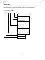
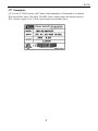
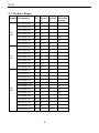
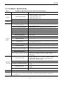
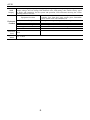
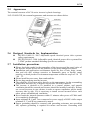
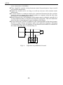
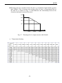

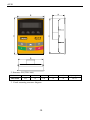
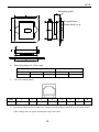
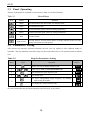
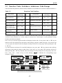
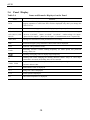
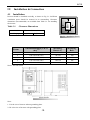
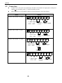
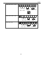
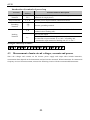
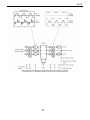
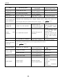
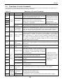
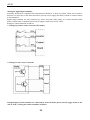
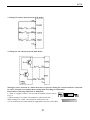
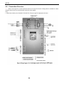
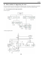
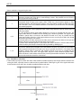
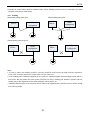
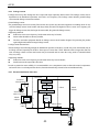
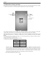
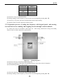
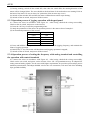
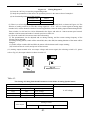
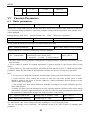
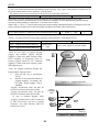
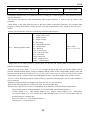
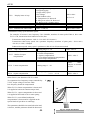
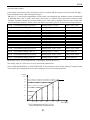
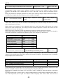
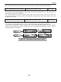
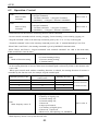
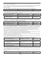
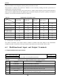
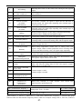
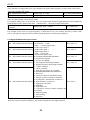
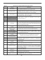
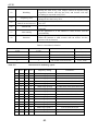
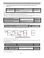
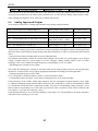
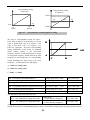
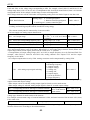
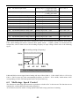
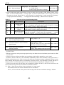
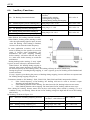
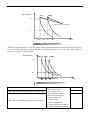
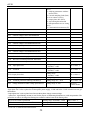
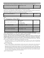
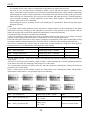
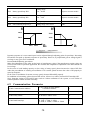
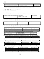
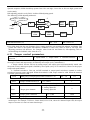
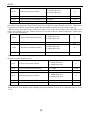
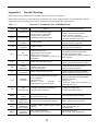
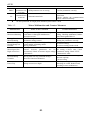
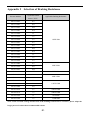
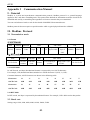
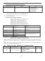
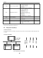
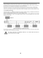
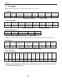
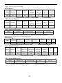
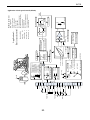
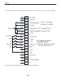
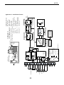
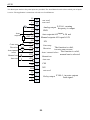
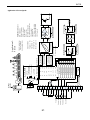
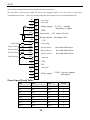
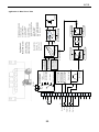
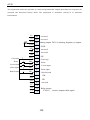
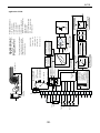
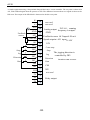
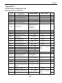
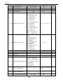
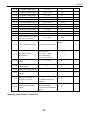
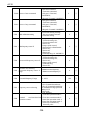
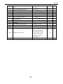
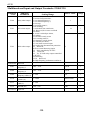
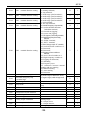
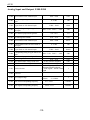
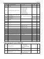
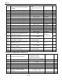

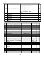
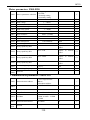
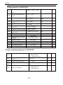
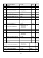

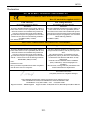
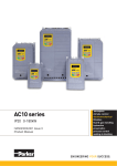
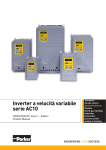
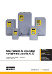

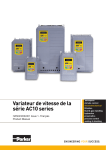
![[AC10] : HA502320U001 : Product Manual to support the Parker](http://vs1.manualzilla.com/store/data/006162733_1-f6c7f4023b54f3efd3a5308c67bef951-150x150.png)