1
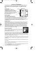
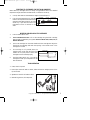
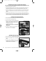
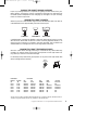
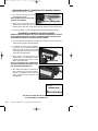
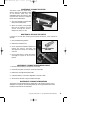
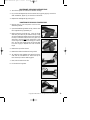
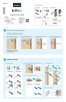
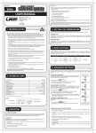
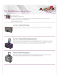
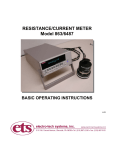
MX500-Universal.qxd
3/29/99
3:57 PM
Page 1
Test Equipment Depot - 800.517.8431 - 99 Washington Street Melrose, MA 02176 - TestEquipmentDepot.com
METCAL MX500 SYSTEM USER GUIDE
BENUTZERHANDBUCH FÜR SYSTEM METCAL MX500
MANUEL D’UTILISATION DU SYSTEME METCAL MX-500
MANUALE DI ISTRUZIONI PER L’USO DI METCAL MX-500
Copyright © 1998, Metcal, Inc. All Rights Reserved 7027-0400 Rev A
MX500-Universal.qxd
3/29/99
3:57 PM
Page 2
MX500-Universal.qxd
3/29/99
3:57 PM
Page 3
METCAL MX500 SYSTEM USER GUIDE
POWER SUPPLY
SYSTEM SET UP AND OPERATION . . . . . . . . . . . . . . . . . . . . . . . . . . . . . . . . . . . . . . . . . . . . . . 2
NO CALIBRATION NEEDED . . . . . . . . . . . . . . . . . . . . . . . . . . . . . . . . . . . . . . . . . . . . . . . . . . . . 3
SOLDER/REWORK HANDPIECE
CHOOSING THE CORRECT TIP FOR THROUGH-HOLE SOLDERING AND SMT TOUCH-UP . . . . . . . . . 4
CHOOSING THE CORRECT TIP FOR SMT REMOVAL . . . . . . . . . . . . . . . . . . . . . . . . . . . . . . . . . . . 5
INSERTING TIP CARTRIDGES INTO THE SOLDER/REWORK HANDPIECE. . . . . . . . . . . . . . . . . . . . . 6
TALON HANDPIECE
SELECTING TIP CARTRIDGES FOR THE TALON HANDPIECE . . . . . . . . . . . . . . . . . . . . . . . . . . . . . 7
INSERTING AND REPLACING TIP CARTRIDGES . . . . . . . . . . . . . . . . . . . . . . . . . . . . . . . . . . . . . 7
TALON OPERATION . . . . . . . . . . . . . . . . . . . . . . . . . . . . . . . . . . . . . . . . . . . . . . . . . . . . . . . . . 7
DESOLDERING HANDPIECE
ATTACHING THE AIR HOSE TO THE DESOLDER HANDPIECE . . . . . . . . . . . . . . . . . . . . . . . . . . . . 8
PREPARING THE DESOLDER HANDPIECE . . . . . . . . . . . . . . . . . . . . . . . . . . . . . . . . . . . . . . . . . 8
INSERTING FILTERS IN THE DESOLDER HANDPIECE . . . . . . . . . . . . . . . . . . . . . . . . . . . . . . . . . 8
CHOOSING THE CORRECT DESOLDER CARTRIDGE . . . . . . . . . . . . . . . . . . . . . . . . . . . . . . . . . . . 9
INSERTING/REPLACING TIP CARTRIDGES INTO THE DESOLDER HANDPIECE . . . . . . . . . . . . . . . . 10
MAINTENANCE: CLEANING THE COLLECTION CHAMBER . . . . . . . . . . . . . . . . . . . . . . . . . . . . . 10
MAINTENANCE: CLEANING THE VENTURI . . . . . . . . . . . . . . . . . . . . . . . . . . . . . . . . . . . . . . . . 11
MAINTENANCE: REPLACING THE VENTURI . . . . . . . . . . . . . . . . . . . . . . . . . . . . . . . . . . . . . . . 11
MAINTENANCE: CLEANING THE DESOLDERING HANDLE. . . . . . . . . . . . . . . . . . . . . . . . . . . . . . 11
MAINTENANCE: CLEANING THE WORKSTAND . . . . . . . . . . . . . . . . . . . . . . . . . . . . . . . . . . . . . 11
MAINTENANCE: REPLACING THE SWIVEL BUSHING . . . . . . . . . . . . . . . . . . . . . . . . . . . . . . . . 12
MAINTENANCE: REPLACING THE UPPER CHAMBER . . . . . . . . . . . . . . . . . . . . . . . . . . . . . . . . 12
MAINTENANCE: REPLACING CARTRIDGE SEALS . . . . . . . . . . . . . . . . . . . . . . . . . . . . . . . . . . . 13
MAINTENANCE: REPLACING CHAMBER SEALS . . . . . . . . . . . . . . . . . . . . . . . . . . . . . . . . . . . . 13
TROUBLESHOOTING
TIP CARTRIDGE WON’T HEAT OR ONE TALON TIP SEEMS TO HEAT POORLY . . . . . . . . . . . . . . . . 14
DESOLDERING TOOL DOES NOT REMOVE SOLDER. . . . . . . . . . . . . . . . . . . . . . . . . . . . . . . . . . . 15
POWER SUPPLY CYCLES ON AND OFF OR WILL NOT TURN ON . . . . . . . . . . . . . . . . . . . . . . . . . 16
EXTENDING TIP LIFE . . . . . . . . . . . . . . . . . . . . . . . . . . . . . . . . . . . . . . . . . . . . . . . . . . . . . . . 16
DETINNED TIPS . . . . . . . . . . . . . . . . . . . . . . . . . . . . . . . . . . . . . . . . . . . . . . . . . . . . . . . . . . 17
SAFETY WITH THE METCAL SYSTEM . . . . . . . . . . . . . . . . . . . . . . . . . . . . . . . . . . . . . . . . . . . 17
SPECIFICATIONS. . . . . . . . . . . . . . . . . . . . . . . . . . . . . . . . . . . . . . . . . . . . . . . . . . . . . . . . . . 18
WARRANTY . . . . . . . . . . . . . . . . . . . . . . . . . . . . . . . . . . . . . . . . . . . . . . . . . . . . . . . . . . . . . 19
®
Copyright © 1998, Metcal, Inc. All Rights Reserved 7027-0400 Rev A
MX500-Universal.qxd
3/29/99
3:57 PM
Page 2
SYSTEM SET UP AND OPERATION
The MX-500P Power Supply is a two port switchable 40-watt power supply with a
separate power cord. The MX-500P Power Supply is an upgraded version of the
Metcal STSS-PS2E. Some of the additional features in this upgrade are described
below.
AUTO SHUT-OFF
Like the STSS-PS2E, the MX-500P is
equipped with a ground sensing feature.
The AMBER LIGHT illuminates when there is
any break in the ground. To reset, turn the
power supply off and back on. If the ground
has not been re-established, the power
supply will remain off.
POWER SWITCH
GREEN POWER ON LIGHT
AMBER AUTO-OFF LIGHT
OVERRIDE
SWITCH
PORT SELECTOR
PORT
INDICATOR
PORTS
TIME-OUT FEATURE
Your MX-500P comes with a time-out
FRONT VIEW
SIDE VIEW
feature designed to maximize the life of
your tip cartridges. The time-out feature works by detecting a load difference at the
tip and sensing whether the tip cartridge has been used during the past 25-30
minutes. If no load change is sensed, the power supply shuts off. This is indicated by
the GREEN LIGHT going off. To reset, turn the power supply off and back on.
OVERRIDE SWITCH
Because the time-out feature works off a load difference, sometimes the power supply
may not sense very light loads. If, for instance, an operator is soldering 30 gauge
wire with an STTC-522 (no sponge wipe), the power supply may shut down after 30
minutes. To ensure operator satisfaction, Metcal has equipped the MX-500P with an
OVERRIDE SWITCH. To disengage the time-out feature, unscrew the set screw several
turns with the provided Allen wrench. To re-engage, turn off the power supply and
screw the set screw clockwise until it feels tight. When the power supply is turned
back on, the time-out feature will be restored.
SETTING UP THE SYSTEM
To set up the power supply, plug the power cord into the three F-CONNECTOR
pronged outlet on the back of the power supply. Plug the cord
into an appropriately rated outlet.
Turn the silver connector at the back of the handle cord assembly
counterclockwise until it is completely flush with the back of the black handle cord
assembly. Then, attach the connector to the port at the front of the power supply by
pushing the connector assembly onto the F-connector and turning the silver handle
cord connector clockwise until it is finger tight.
You can attach an additional handpiece into the other port, or leave the port open for
the addition of another handpiece later. If desired, label the ports according to
handpiece type.
Place tool(s) into the appropriate workstand(s). Select a tip cartridge and insert it into
the handpiece.
Power the system on by pressing the switch on the top left hand side to the “on”
position. The green light should come on.
Move the PORT SELECTOR to the port which corresponds to the handpiece you wish to
use. The PORT INDICATOR will be next to the appropriate port.
2
Copyright © 1998, Metcal, Inc. All Rights Reserved 7027-0400 Rev A
MX500-Universal.qxd
3/29/99
3:57 PM
Page 3
NO CALIBRATION REQUIRED
METCAL® SMARTHEAT® SOLDERING, DESOLDERING, AND REWORK SYSTEMS DO NOT REQUIRE
SYSTEM CALIBRATION FOR TEMPERATURE.
A Metcal System is comprised of a power supply with handle/cord assembly and a tip
cartridge. Each cartridge is equipped with a self-regulating heater, which senses its
own temperature and tightly maintains its pre-set idle temperature for the life of the
cartridge. The heater temperature is set by the atomic structure of the heater material.
It cannot be adjusted, and does not require any adjustment.
The power supply with handle/cord assembly does not contain the heater or any tip
temperature sensors, but simply provides the current to the heater. Any expected
variability or drift in the power supply over its life does not adversely affect its ability
to maintain the necessary current to the heater. There are no adjustments to be made.
The term calibration implies that because of inherent shift over time in a system,
periodic adjustment must be made to maintain performance. Calibration schedules
are normally based on anticipating when an out-of-tolerance condition will occur and
calibrating or adjusting prior to this event. In a Metcal System, there is nothing to
adjust, so the system cannot be changed from its initial state. Therefore, NO
CALIBRATION is required. Metcal tip cartridges control temperature inherently by
the physical properties of their materials to dynamically respond to loads.
Those companies or individuals requiring periodic verification of system performance
may do so in the following ways:
• Measure the performance of the system in 'time required to solder a defined
number of loads', or
• Measure tip idle temperature as it equates to this performance, or
• Observe start up and idle power with a Metcal Net Power Meter.
Copyright © 1998, Metcal, Inc. All Rights Reserved 7027-0400 Rev A
3
MX500-Universal.qxd
3/29/99
3:57 PM
Page 4
CHOOSING THE CORRECT TIP CARTRIDGE FOR THROUGH-HOLE SOLDERING AND
SMT TOUCH-UP
Proper tip cartridge selection is important for getting the best results from your
Metcal System. Choosing the right tip will maximize your soldering performance at
the lowest possible temperature, and will ensure you the longest tip life possible.
CHOOSE THE CORRECT GEOMETRY
For STTC soldering tips, you want to pick a tip geometry which will maximize
contact with the connection. A flat, blunt tip will transfer more heat than a fine,
pointed one. Choosing the largest tip possible will both improve performance
(enabling you to get more heat at lower temperatures), and enhance tip life.
CORRECT
TOO SMALL
TOO LARGE
CHOOSE THE CORRECT SERIES
Each Metcal cartridge is specially designed for high power delivery, which means that
you can often solder with a Metcal cartridge at a temperature 100°F or more lower
than with a conventional iron. Since Metcal tip cartridges sense thermal loads and
respond to them, you need only approximate the size of the loads you will be working
with. Start with a lower temperature, going to a higher temperature only when
necessary.
FOR MOST APPLICATIONS
HEAVY GROUND PLANES
WORKING WITH NO-CLEANS
THERMALLY SENSITIVE APPLICATIONS
600 SERIES
700 SERIES
500 SERIES
500 SERIES
LOT 1212
LOT CODE
STTC-036
SERIES/STYLE
WHEN SOLDERING MULTI-LEAD PACKAGES
Let Metcal’s Multi-lead Soldering (“hoof”) tip cartridge or one of Metcal’s blade tips
do the work for you! It’s faster than laboriously soldering point to point. It’s safer than
drag soldering with a bent hook tip, which can abrade leads and shorten tip life. For
more information, call your Authorized Distributor.
BLADE
4
M U LT I - L E A D
SOLDERING
Copyright © 1998, Metcal, Inc. All Rights Reserved 7027-0400 Rev A
MX500-Universal.qxd
3/29/99
3:57 PM
Page 5
CHOOSING THE CORRECT TIP CARTRIDGE FOR SMT REMOVAL
CHOOSE THE CORRECT GEOMETRY
First, measure the dimensions of your component. Then, using the SMTC charts which
are available from your local distributor or on Metcal’s web page (www.metcal.com),
look up your component description, and cross match it to the dimensions listed
(sometimes components with the same description can have different dimensions). If
this doesn’t work, try looking up the dimensions of other types of components; one of
them may work.
The tip you choose must match your component. A “near fit” is not good enough for
most applications. The leads must be contacted on all sides, ensuring even
performance.
SLOT
TUNNEL
QUAD
QUAD
DUAL QUAD*
THE SIMPLEST WAYS TO GET THE RIGHT TIP
Many customers have said that measuring their components and matching them up to
a chart can be difficult. That’s why Metcal developed the SMTC Tip Template Guide.
The SMTC Tip Template is a series of ESD-safe, clear plastic templates in an easy-to-use
book. Look up what type of component you have, and turn to one of our templates. Lay
the template over the component, and, if it fits and has the correct lead count, you’ve
found your tip. There’s also an outline of each tip at the edge of the template, so you can
turn the template and “try out” the tip on the component.
In addition, Metcal has a “tip picker” software program that may be of use to you.
Contact your distributor or www.metcal.com for more information.
If you are still having problems, your local Metcal Distributor or Representative can
help. Please give them a call.
CHOOSE THE CORRECT SERIES
Each Metcal cartridge is specially designed to deliver high power in response to loads.
For this reason, you can often rework with a Metcal cartridge at a temperature 100°F
or more lower than with a conventional iron. In Metcal’s tip listing, the recommended
Series is included in its own column. If you think you need a different series than
recommended, call your Metcal Distributor or Representative.
Copyright © 1998, Metcal, Inc. All Rights Reserved 7027-0400 Rev A
5
MX500-Universal.qxd
3/29/99
3:58 PM
Page 6
INSERTING TIP CARTRIDGES INTO THE SOLDER/REWORK HANDPIECE
1. Make sure the system is turned off.
2. Insert the tip cartridge into the soldering handpiece by pushing in the “back end”
of the cartridge (the end without the tip) as far as it will go. You will feel a slight
click as it locks into place
THIS
NOT THIS
REPLACING TIP CARTRIDGES
NOTE: EVEN AFTER THE SYSTEM IS TURNED OFF OR TIMED OUT, THE TIP CARTRIDGE MAY BE HOT
1. Make sure the system is turned off.
2. Pull out the cartridge using the Cartridge Removal Pad
3. Push a new cartridge into the handle as discussed above.
4. Push the power switch “on”. The new cartridge should heat up to temperature
quickly.
DO NOT USE METAL TOOLS SUCH AS PLIERS TO REMOVE TIP CARTRIDGES!
6
Copyright © 1998, Metcal, Inc. All Rights Reserved 7027-0400 Rev A
MX500-Universal.qxd
3/29/99
3:58 PM
Page 7
SELECTING TIP CARTRIDGES FOR THE TALON HANDPIECE
Metcal TATC tip cartridges come in a variety of tip geometries and in two standard
temperature ranges (500 Series and 600 Series). To select the correct tip:
1.
Use a tip that meets or overextends the length of the lead footprint.
2.
Pick the lowest temperature tip cartridge
that will accomplish the task. Start with a
500 Series cartridge and switch to a 600
Series only if you need more heat. The
temperature series is marked on the
shaft.
PART NUMBER
LOT CODE
TATC-504
INSERTION MARK
LOT-YDDD
TEMPERATURE SERIES
INSERTING AND REPLACING TIP CARTRIDGES
1.
Push the Power Switch “Off.”
2.
THE TIP CARTRIDGE MAY BE HOT. Pull out the cartridge using the black Cartridge
Removal Pad included with your system. DO NOT USE METAL TOOLS (PLIERS, ETC) TO
REMOVE CARTRIDGES!
3.
Push a new cartridge into the solder handle with the Cartridge Pad. Align the
flat side of the cartridge shaft with the opening in the handle. Push in the
cartridge until it seats.
4.
The cartridge is fully seated when the
insertion mark is flush with the front of the
handle. Do not push past this mark. Both
cartridges must be inserted properly.
5.
Push the Power Switch “On.” The new tip
cartridge will heat up to temperature in less
than 20 seconds.
INSERTION MARK
TALON OPERATION
1. Clean, then tin tips well.
2. Ensure tips contact all leads on device, either the bevel or straight portion of the
tip can be used.
3. Squeeze tool. Wait for all leads to reflow.
4. Maintaining pressure, lift component.
Copyright © 1998, Metcal, Inc. All Rights Reserved 7027-0400 Rev A
7
MX500-Universal.qxd
3/29/99
3:58 PM
Page 8
ATTACHING THE AIR HOSE TO THE DESOLDER HANDPIECE
NOTE: SAFETY GLASSES SHOULD BE WORN WHEN WORKING WITH ANY COMPRESSED AIR LINES
1. Make sure the system is turned off.
2. Clamp the Desoldering Power Cord to the air line using the clamp, making sure
that the end of the Power Cord is four inches beyond the end of the air line
3. Attach the desoldering air line to the DS1 handpiece by using the swivel fitting. A
wrench is not needed, but the connection should be as tight as your fingers can
make it.
4. Attach the other end of the Air Line to your air supply, using a filter/regulator to
maintain the proper psi. Operating the desoldering tool above 100 psi could cause
the air line to rupture. The tool works best when the air supply is set at 80 psi.
PREPARING THE DESOLDER HANDPIECE
1. Open the handpiece by sliding the top grooved portion forward.
2. Pivot the top of the handpiece open.
3. Apply a thin layer of silicone grease inside
the top of the chamber. This will aid in
keeping the roof of the chamber clear of
incidental solder splatter.
WARNING: SILICONE GREASE CAN CONTAMINATE
SOLDER JOINTS!
4. Inspect the chamber seal to be sure it is
clean and is not cut or damaged.
INSERTING FILTERS INTO THE DESOLDER HANDPIECE
1. Open the handpiece. CAUTION: THE TIP MAY BE HOT!
2. Insert a new Chamber Filter in the square
cavity.
3. Insert a new Chamber Liner in the
rectangular cavity. Be sure to orient the tab
toward the back of the handpiece.
8
Copyright © 1998, Metcal, Inc. All Rights Reserved 7027-0400 Rev A
MX500-Universal.qxd
3/29/99
3:58 PM
Page 9
CHOOSING THE CORRECT DESOLDER CARTRIDGE
Proper tip cartridge selection is important for getting the best results from your
Metcal System. Choosing the right tip cartridge will maximize your performance at
the lowest possible temperature. Since changing tip cartridges is so quick and easy,
there is no need to compromise.
CHOOSING THE CORRECT GEOMETRY
Select a tip with an inside diameter larger than the lead diameter. Select a tip with an
outside diameter that is approximately the same size as the pad.
CORRECT
TOO SMALL
TOO LARGE
A standard STDC cartridge can desolder a maximum lead length of 0.0170." For fast,
safe removal of devices that are difficult to reach on densely populated boards, or to
remove long pin connectors, try the STDC long reach cartridges. They are identical to
standard STDC tip cartridges, but with a 0.46" long extension at the tip.
CHOOSING THE CORRECT TEMPERATURE (SERIES)
Start with a 600 Series cartridge, switching to a 700 Series only where absolutely
necessary; for example, when working with ground planes or multi-layer boards. For
long reach tips, start with a 700 Series cartridge.
For extremely heavy loads tied to ground planes, or very thick multi-layer boards, 800
Series cartridges may be necessary.
End-on
View of Tip
Lead
A
Pad
B
A
B
InsideOutside
Diameter
Diameter
(A)
(B)
0.025"
0.055"
0.030"
0.066"
0.040"
0.070"
0.050"
0.080"
0.060"
0.090"
0.095"
0.125"
Part Number
600
Series
STDC-002
STDC-003
STDC-004
STDC-005
STDC-006
STDC-007
700
Series
STDC-102
STDC-103
STDC-104
STDC-105
STDC-106
STDC-107
800
SERIES
STDC-802
STDC-803
STDC-804
STDC-805
STDC-806
STDC-807
LONG
Reach*
N/A
STDC-703L
STDC-704L
STDC-705L
N/A
N/A
long reach
800 series
N/A
STDC-803L
STDC-804L
STDC-805L
N/A
N/A
*When using long reach cartridges, 600 Series heat delivery is insufficient for fast, safe device removal.
Therefore, long reach desolder tips are only available in 700 and 800 Series.
Copyright © 1998, Metcal, Inc. All Rights Reserved 7000-0760 Rev D
9
MX500-Universal.qxd
3/29/99
3:58 PM
Page 10
INSERTING/REPLACING TIP CARTRIDGES INTO THE DESOLDER HANDPIECE
1. Make sure the system is turned off.
2. Pull out the cartridge using the
Cartridge Removal Pad
DO NOT USE METAL TOOLS SUCH AS PLIERS
TO REMOVE TIP CARTRIDGES!
TAILPIPE IS ORIENTED DOWN
3. Insert the tip cartridge into the
desoldering handpiece by pushing in the “back end” of the cartridge (the end
without the tip) as far as it will go. Notice that the tailpipe must be oriented down.
4. Turn on the system. The new cartridge should heat up to temperature quickly.
MAINTENANCE: CLEANING THE COLLECTION CHAMBER
WARNING: ALTHOUGH THE DESOLDER TOOL CAN BE OPENED AND CLEANED WHILE THE SYSTEM IS
ON, THE CARTRIDGE WILL BE HOT. USE EXTREME CAUTION WHEN OPENING THE TOOL SO AS TO
AVOID BURNING YOUR FINGERS OR HAND ON THE EXPOSED CARTRIDGE
1. Open the Desoldering Handle and remove the Chamber Liner. The liner has a
convenient lift-out tab to facilitate removal.
2. In addition to replacing the Chamber
Liner when full, you should periodically
scrape any solder or resin from the inside
of the upper half of the handle in the area
around the Cartridge tailpipe.
3. Apply a layer of silicone grease to the
surface after it is scraped clean. Check
that the chamber seal surface is clean
before closing the handle.
FILTER
CHAMBER LINER
NOTE: SILICONE GREASE WILL CONTAMINATE
ELECTRONIC CONNECTIONS AND SHOULD BE USED
WITH CARE AROUND ELECTRONIC PARTS.
4. Two cleaning brushes are included with
your system. Use these with Isopropyl
Alcohol or detergent to clean flux and
solder residue from the chamber and
cartridge seals.
CLEANING THE CARTRIDGE CHAMBER
CARTRIDGE BRUSH
GENERAL PURPOSE BRUSH
NOTE: DO NOT USE FREON, KETONES, OR TRICHLORS
TO CLEAN CHAMBER OR CARTRIDGE SEALS.
10
Copyright © 1998, Metcal, Inc. All Rights Reserved 7027-0400 Rev A
MX500-Universal.qxd
3/29/99
3:58 PM
Page 11
MAINTENANCE: CLEANING THE VENTURI
The Venturi Filter will collect resins
and will need to be replaced as often
as use dictates. After time, the
passageways below the filter will also
clog with resin. When this happens,
follow the procedure below.
1. Open the Desoldering Handle and
remove the chamber filter.
FILTER
CHAMBER LINER
2. Squirt flux cleaner in the passage,
then pull the trigger to suck the
solvent through the Venturi.
Repeat until Venturi is clear.
MAINTENANCE: REPLACING THE VENTURI
If vacuum is still low after checking and cleaning the Venturi, it will have to be
replaced.
1. Open the Desoldering Handle.
2. Remove the Chamber filter.
3. Use an appropriate slotted screwdriver to
remove the Venturi cartridge. The
cartridge should screw out normally. Do
not force.
VENTURI CARTRIDGE
GOES HERE
4. Use a torque driver to install the Venturi
Cartridge to a torque of 10 to 15 inchpounds.
MAINTENANCE: CLEANING THE DESOLDERING HANDLE
1. Remove the Desoldering Cartridge from the handle.
2. Disconnect the power cord and air hose from the handle.
3. Remove the cartridge and chamber seals.
4. Clean the handle in a mild vapor degreaser or ultrasonic bath.
5. Allow time for the tool to dry, then replace the seals.
MAINTENANCE: CLEANING THE WORKSTAND
The exterior of the workstand can be cleaned with a soft bristle brush and a mild
detergent. The cradle can be cleaned separately by removing the attachment screw,
located on the bottom of the workstand.
Copyright © 1998, Metcal, Inc. All Rights Reserved 7027-0400 Rev A
11
MX500-Universal.qxd
3/29/99
3:58 PM
Page 12
MAINTENANCE: REPLACING THE SWIVEL BUSHING
1. Turn off shop air.
2. Unscrew air hose from the desolder tool.
3. Using an adjustable wrench, unscrew the swivel bushing.
Note: the swivel bushing is secured in the tool with a sealant so it may be difficult
to remove.
4. When you remove the swivel bushing, you will see a spring. Keep it in place.
5. Make sure the area where the swivel bushing screws in is clean of foreign materials
(this may require removing the spring temporarily).
6. Wrap Teflon pipe sealant around the end of the swivel bushing and with the spring
in place, screw the swivel bushing into the back of the desolder tool using a torque
wrench to 30-50 in-lbs.
7. Screw in the air hose onto the swivel bushing.
8. Turn on shop air and check for leaks.
MAINTENANCE: REPLACING THE UPPER CHAMBER
For an illustration of many of the steps in this technique, see opposite page.
1. Remove the power cord from back of the upper chamber.
2. Open the upper chamber.
3. Insert a long, thin tool in the back hinge where the upper chamber hinges to the
tool handle assembly.
4. Push tool inwards and pull the upper chamber away from the tool handle
assembly.
5. Completely remove upper chamber.
6. Remove old pins and springs from the front and back pin bores.
7. Insert two new springs, and two new hinge pins, into the pin bores on either end
of the tool handle assembly. Ensure that the smaller, tapered ends of the hinge
pins, are pointing outward.
8. Install upper chamber assembly onto tool handle assembly by pushing the hinge
pins into their bores until the arms of the upper chamber assembly will slide onto
the handle assembly. The hinge pins should slide out into their pilot holes in the
arms of the upper chamber.
9. Check the functioning of the slide latch and hinge by operating the latch, opening
and closing the upper body a few times. The parting lines (gaps) between the rear
of the chamber and the top rear of the right handle should be parallel.
12
Copyright © 1998, Metcal, Inc. All Rights Reserved 7027-0400 Rev A
MX500-Universal.qxd
3/29/99
3:58 PM
Page 13
MAINTENANCE: REPLACING CARTRIDGE SEALS
1. Turn off the system and remove the desolder cartridge.
2. Pry out the cartridge seal (at the front end of tool) by gently prying it out with a
small screwdriver, paper clip, or other blunt instrument.
3. Replace the cartridge seal by pushing it in.
MAINTENANCE: REPLACING CHAMBER SEALS
1. Remove the air line and power cord from the
desoldering handle.
2. Open the desoldering handle and lay it down with
the hinge side facing up toward you
3. Before removing the hinge pins, cover the hinge
area with your hand as you remove the top. They
are spring loaded and might shoot out of the tool as
the top is removed. Take the end of a paper clip
and push it into the small hole at the front or rear
of the hinge. This will push the hinge pin into the
tool. You can then wiggle the top of the tool away
from the hinge pin. Repeat this with the other
hinge.
4. Remove the top half of the tool.
5. Remove the solder chamber seal using a knife.
6. To install the new chamber seal, start with a short
side, and use a screwdriver or other blunt tip to
tuck the seal lip into the retaining grove
7. Next, tuck the other short side.
8. Finish with the long sides.
Copyright © 1998, Metcal, Inc. All Rights Reserved 7027-0400 Rev A
13
MX500-Universal.qxd
3/29/99
3:58 PM
Page 14
TROUBLESHOOTING GUIDE
TIP CARTRIDGE WON’T HEAT OR ONE TALON TIP SEEMS TO HEAT POORLY
1. Is the green light on? If not, the MX-500P time-out feature may have shut the
power supply off. To reset, turn the power supply off and back on.
2. Be sure the tip cartridge is pushed all the way into the handpiece.
3. Be sure that the switch is positioned on the port you are using.
4. Check the connectors. The connector must be tightened securely to the power
supply output connector.
5. SOLDERING AND DESOLDERING HANDPIECES ONLY: If you have another cartridge, turn
off the system and replace the cartridge. Then, turn the system back on. If the new
cartridge heats, discard the old cartridge or call Metcal Customer Service to see if
it is still in warranty
TALON HANDPIECE ONLY: If one side appears to be operating better than the other,
check to see if both tips are the same temperature series, make sure tips are
properly tinned, and check for damage.
If neither tip appears to work, and since both cartridges have to be functioning for
either to work, you must test each cartridge using the following procedure:
a. Insure that both cartridges are fully seated.
b. With cartridge “A” inserted, replace cartridge “B”.
c. Test. If both cartridges function, cartridge “B” is bad. Check warranty and call
Metcal Customer Service, if applicable, to return. If neither cartridge
functions, proceed to step D.
d. Reinsert cartridge “B” and replace “A” with a new cartridge. Test. If both
cartridges function, cartridge “A” is bad. Check warranty and call Metcal
Customer Service, if applicable, to return. If neither cartridge functions,
proceed to step E.
e. Replace “B” with a new cartridge. Test. If both new cartridges function, both
“A” and “B” are bad. Check warranty and call Metcal Customer Service, if
applicable, to return.
6. Check to see if the amber light is on. If the amber light is on, something has
triggered the automatic “Auto-Off” feature. Turn the system off and then on again
to reset this feature. If the amber light remains on, you may have a bad handpiece
or a bad cartridge.
7. The power supply contains an over-temperature cutoff feature. A system operated
at a high duty cycle and/or in a high ambient temperature may reach a
temperature that will trip the resettable thermal switch. After cutoff and
shutdown, the power supply will remain off until it cools to an acceptable
operating temperature, at which time it will return to normal operation. If, after
waiting for cool down, the unit still does not turn on, remove the fuse (located
next to the power cord inlet) and check for damage. Replace if blown.
14
Copyright © 1998, Metcal, Inc. All Rights Reserved 7027-0400 Rev A
MX500-Universal.qxd
3/29/99
3:58 PM
Page 15
TROUBLESHOOTING GUIDE
DESOLDERING TOOL DOES NOT REMOVE SOLDER
1.
Check if the tip is heating up by applying solder to the tip. If it does not heat,
follow the steps under “Tip Will Not Heat” earlier in this manual.
2.
Turn the power supply off.
3.
Open the handle.
4.
Replace the Chamber Filter if it appears dirty and full of flux.
5.
Replace the Chamber Liner if it is full.
6.
Lay the edge of your hand over the top of the collection chamber to provide a
seal. Press the trigger of the tool and verify that you feel a strong suction against
your hand.
7.
If the suction is not strong, proceed to step 12. If the suction is strong and you
replaced either the chamber filter or liner, close the tool, insert a cartridge, turn
the system on and press the trigger while melting some solder with the tip.
8.
If the solder is not sucked into the tool, try cleaning the tip with a thin wire or
Tip Cleaner.
9.
If this does not help, turn the system off, remove the cartridge, and visually
inspect the cartridge seal and chamber seal for leaks (tears, nicks, debris). Close
the tool, remove the cartridge, and place your thumb over the front opening of
the tool while pressing the trigger.
10. If you do not feel a strong suction, try replacing the chamber seal.
11. If you still do not feel a strong suction, adjust the set screw under the front lip of
the top slide latch.
12. If the suction is weak, check the air pressure (80 psi is ideal).
13. If there is still no vacuum generated by the unit, check all air lines to the handle
for cuts, kinks, or obstructions.
14. Clean the Venturi. Squirt flux cleaner in the passage (or on a fresh Venturi), then
pull the trigger for a few seconds (with the handle open).
15. If this does not work, replace the Venturi cartridge as described in “Replacing
the Venturi”.
If the above steps do not result in proper performance, call your Metcal representative
or Metcal Technical Service at 800-776-1778 from inside the United States or 1-650325-3291 from outside of the United States.
Copyright © 1998, Metcal, Inc. All Rights Reserved 7027-0400 Rev A
15
MX500-Universal.qxd
3/29/99
3:58 PM
Page 16
TROUBLESHOOTING GUIDE
POWER SUPPLY CYCLES ON AND OFF OR WILL NOT TURN ON
1. Is the green light on? If not, the MX-500P time-out feature may shut the power
supply off. To reset, turn the power supply off and back on. To reset, turn the
power supply off and back on. If this does not help, check to see if the power
supply is plugged into the wall.
2. The power supply unit contains an over-temperature cutoff feature. A system
operated at a high duty cycle and/or in a high ambient temperature may reach a
temperature that will trip the resettable thermal switch. After cutoff and
shutdown, the power supply unit will remain off until it cools to an acceptable
operating temperature, at which time it will return to normal operation.
EXTENDING TIP LIFE
1. Each day, remove, inspect, and clean the cartridge shaft and handle using
denatured alcohol and a clean cloth. Stubborn flux deposits on the shaft (and on
the entire SMTC or TATC tip) can be removed using a brass brush. Do not use a
brass brush on the tip itself for STTC tips as it will damage the plating and
shorten tip life.
2. After you turn on the system, and each time you return the tip to the holder,
apply rosin core solder to the tinned surfaces of the tip. The solder protects the tip
from oxidation and prolongs the life of the tip.
3. Use the lowest tip temperature that will do the job. Lower temperatures decrease
tip oxidation and are easier on the components being joined.
4. Use fine point tips only when necessary. The plating on fine precision tips is less
durable than the plating on blunter tips.
5. Do not use the tip as a prying tool. Bending the tip can cause the plating to crack,
shortening tip life.
6. Use the minimum activation flux necessary to do the job. Higher activation flux is
more corrosive to the tip plating.
7. When making a solder connection, apply fresh solder to the members being
joined, not to the hot soldering tip.
8.
Switch the system off when not in use.
9. Don’t apply pressure to the tip. More pressure does not equal more heat. To
improve heat transfer, use solder to form a thermal bridge between the tip and the
solder joint.
10. Clean the tip on a clean, wet sponge -- not on a rag or dirty, dry sponge.
16
Copyright © 1998, Metcal, Inc. All Rights Reserved 7027-0400 Rev A
MX500-Universal.qxd
3/29/99
3:58 PM
Page 17
DETINNED TIPS
A detinned tip is one not wetted with solder. This exposes the plating to oxidation
and degrades the heat transfer efficiency of the tip. Detinning is caused by:
a.
b.
c.
d.
Failure to keep the tip covered with fresh solder during idling periods.
High tip temperatures.
Lack of sufficient flux in soldering operations.
Wiping the tip on dirty or dry sponges and rags. (Always use a clean, wet,
industrial grade, sulfur-free sponge.)
e. Impurities in the solder, iron plating, or on the surfaces to be soldered.
To restore a detinned tip:
1. Remove the tip cartridge from the solder handle and allow the tip to cool down.
2. Remove scale and oxides from the tinned area of the tip with 80-grit abrasive
polyurethane foam stock (Plato AB-3 Polishing Bar or Multicore Tip
Tinner/Cleaner or equivalent) or a 100-grit emery cloth.
3. Wrap rosin core solder (0.031” diameter or larger) around the newly exposed iron
surface, insert the tip cartridge into the handle, and turn on the system.
NOTE: Detinned tips are preventable with proper daily care!
SAFETY WITH THE METCAL SYSTEM
Metcal Systems provide unique safety advantages due to our proprietary SmartHeat
technology that is unavailable from any other tool. However, maximum safety
requires the user’s participation.
1. Although Metcal Systems offer superior EOS (Electrical Overstress) protection,
periodic checks of the instrument cord should be incorporated into standard
operator maintenance procedures. Also, make sure the instrument cord is in good
working condition with no damage to the shielding. caution: failure to do so
could result in intermittent EOS conditions that may be detrimental to EOSsensitive devices. Operators should make weekly checks to ensure that the
instrument cord is securely fastened to the power supply. This is done by making
sure the connection is finger-tight.
The recommended frequency and methods for checking shield integrity of the
instrument cord are very dependent on the applications and available test
equipment. For suggestions as to how to implement such checks, contact your
local Metcal representative or Metcal direct.
2. Since Metcal tip cartridges heat up in seconds, the MX-500P power supply should
be turned off when not in use even though it is equipped with a time-out feature.
This not only saves tip life and energy, but minimizes the danger of injury caused
by accidental contact with unattended hot soldering tools.
3. Metcal systems have the smallest exposed heated area of any tool on the market,
but always remember to treat this area as if it were at 600°F or higher. Always turn
off the system prior to tip removal and insertion, and always use a Cartridge
Removal Pad to remove tips.
Copyright © 1998, Metcal, Inc. All Rights Reserved 7027-0400 Rev A
17
MX500-Universal.qxd
3/29/99
3:58 PM
Page 18
SYSTEM SPECIFICATIONS
POWER SUPPLY
Tip-to-Ground Potential
Tip-to-Ground Resistance
Idle Temperature Stability
Ambient Operating Temp.
Maximum Enclosure Temp.
Thermal Switch
Input Line Voltage
Input Line Frequency
Fuse
Output Power
Output Frequency
Auto-Off Feature
Power Cord (3-wire)
WxHxD
Weight
Standards Compliance
SOLDERING HANDPIECE
Weight
Handle Cord Assembly
ESD Materials
TALON HANDPIECE
Weight (handle)
Handle Cord Assy
ESD Materials
DESOLDERING HANDPIECE
Input Air Pressure
Vacuum
Weight
Handle Cord Assembly
ESD Materials
TIP CARTRIDGES
STTC Startup Power
Maximum Temperature
18
< 2 mV True RMS, 50-500 Hz
< 2 ohms
DC, unit on
± 2° F (± 1.1°C)
Still air
50 - 104° F (10 - 40 °C)
150 ° F (65°C)
Setpoint at 150 ± 3° F (66 ± 1.2°C)
Auto-reset once cooled to 110° F (43°C)
90 - 130 VAC (-11)
190-260VAC (-21)
45 - 70 Hz (-11)
50-60Hz (-21)
250V, 1.25 A, “Slo-Blo”
40 Watts maximum
@ 72°F (22°C) ambient temperature
13.56 MHz
10 millisecond lag time
6 ft (183 cm) 18/3 SJT
5.3” x 9.5” x 4.7” (13.5cm x 24.1cm x 11.9cm)
7.5 lbs. (3.41kg)
MIL-STD-2000, -1686, -45743E, WS-6536D/E
2 oz (56.7 g)
6 ft (183 cm) carbon loaded silicone, shielded
105 - 1012 ohm/square as per ASTM D257
(105 - 109 ohm/square where possible)
2 oz (56.7 g)
6 ft (183 cm)
Carbon loaded silicone, shielded
105 - 1012 ohm/square as per ASTM D257
(105 - 109 ohm/square where possible)
60-100 psig required
18 inches Hg minimum
10.5 oz (298 g)
6 ft (183 cm) carbon loaded silicone, shielded
105 - 1012 ohm/square as per ASTM D257
(105 - 109 ohm/square where possible)
500 Series > 25 Watts
600 Series > 25 Watts
700 Series > 30 Watts
500 Series ≤ 575°F (302°C)
600 Series ≤ 675°F (352°C)
700 Series ≤ 775°F (405°C)
Copyright © 1998, Metcal, Inc. All Rights Reserved 7027-0400 Rev A
MX500-Universal.qxd
3/29/99
3:58 PM
Page 19
WARRANTY
Metcal, Inc. warrants Power Supplies against any defects in materials or workmanship
for four (4) years from the date of purchase by the original owner. All Handle/Cord
Assemblies and the DS1 Desolder Tool are warranted against any defects in materials
or workmanship for one (1) year from the date of purchase by the original owner.
Metcal warrants all other products except consumables against any defects in materials
or workmanship for ninety (90) days from the date of purchase by the original owner.
This Warranty excludes normal maintenance and shall not apply to any opened,
misused, abused, altered or damaged items.
Metcal warrants that the heater in its STTC, STDC, TATC, SDC, and SSC tip cartridges
will operate according to specifications for the lifetime of the tip plating. Because tip
plating is mainly dependent upon the user’s application and practices, tip cartridges
are not warranted for plating wear. Tip cartridges are warranted against any defects in
materials or workmanship. Misused, abused, altered or damaged tip cartridges are not
warranted.
All tip cartridges that fail to heat will be repaired or replaced at Metcal’s option.
Metcal will repair or replace (at Metcal’s sole option) a Power Supply that fails in
normal use within three (3) years after the expiration of the four-year warranty at the
then current repair or exchange rate. This offer does not apply to any previously
opened, modified, repaired, altered, misused or damaged Power Supply.
This Warranty excludes normal maintenance and shall not apply to any opened,
misused, abused, altered or damaged items. If the product should become defective
within the warranty period, Metcal, Inc., will repair or replace it free of charge at its
sole option. The replacement item(s) will be shipped, freight prepaid, to the original
purchaser.
The warranty period will start from the date of purchase. If the date of purchase cannot
be substantiated, the date of manufacture will be used as the start of the warranty period.
99 Washington Street
Melrose, MA 02176
Phone 781-665-1400
Toll Free 1-800-517-8431
Visit us at www.TestEquipmentDepot.com
Copyright © 1998, Metcal, Inc. All Rights Reserved 7027-0400 Rev A
19