1
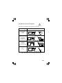
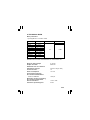
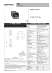
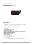
TRANSDUCER SUPPLIED FROM A CURRENT LOOP P17 TYPE USER’S MANUAL 1 2 CONTENTS 1. Application .............................................................................. 5 2. Transducer set ........................................................................ 5 3. Basic requirements and operational safety ........................ 5 4. Instalation ................................................................................ 8 4.1. Way of fixing .................................................................................... 8 4.2. External connection diagrams ......................................................... 9 5. Service ................................................................................... 10 6. Technical data ........................................................................ 11 7. Ordering codes ..................................................................... 13 8. Maintenance and warranty .................................................. 14 3 4 1. APPLICATION The P17 transducer with 6.2 mm width, supplied from a current loop, converts the signal from a temperature sensor or standard voltage signal into a 4...20 mA standard signal. 2. TRANSDUCER SET The set of the P17 transducer is composed of: - P17 transducer - user’s manual - warranty card 1 pc. 1 pc. 1 pc. When unpacking the instrument, please check whether the type and execution code on the data plate correspond to the order. 3. BASIC REQUIREMENTS AND OPERATIONAL SERVICE Symbols located in this user’s manual mean: WARNING! Warning of potential, hazardous situations. Especially important. One must acquaint with this before connecting the P15 transducer. The non-observance of notices marked by these symbols can occasion severe injuries of the personnel and the damage of the instrument. ? CAUTION! Designates a general useful note. If you observe it, handling of the recorder is made easier. One must take note of this, when the instrument is working inconsistently to the expectations. Possible consequences if disregarded ! In the security scope the transducer meets the requirements of the EN 61010 -standard. 5 Remarks concerning the operator safety: 1. General - The P17 transducer is destined to be mounted on a 35 mm DIN rail. - Non-authorized removal of the required housing, inappropriate use, incorrect installation or operation, create the risk of injury to personnel or damage to equipment. For more detailed information please study this user’s manual. - All operations concerning transport, installation, and commissioning as well as maintenance must be carried out by qualified, skilled personnel and national regulations for the prevention of accidents must be observed. - According to this basic safety information, qualified, skilled personnel are persons who are familiar with the installation, assembly, commissioning, and operation of the product and who have qualifications necessary for their occupation. 2. Transport, Storage Please observe the notes on transport, storage and appropriate handling. Observe the climatic conditions given in technical data. 3. Installation - The transducer must be installed according to the regulation and instructions given in this user’s manual. - Ensure proper handling and avoid mechanical stress. - Do not bend any components and do not change any insulation distances. - Do not touch any electronic components and contacts. - Instruments may contain electrostatically sensitive components, which can easily be damaged by inappropriate handling. - Do not damage or destroy any electrical components since this might endanger your health! 6 4. Electrical Connection - Before switching the instrument on, one must check the correctness of connection to the network. - In case of the protection terminal connection with a separate lead one must remember to connect it before the connection of the instrument to the mains. - When working on live instruments, the applicable national regulations for the prevention of accidents must be observed. - The electrical installation must be carried out according to the appropriate regulations (cable cross-sections, fuses, PE connection). Additional information can be obtained from the user’s manual. - The documentation contains information about installation in compliance with EMC (shielding, grounding, filters and cables). These notes must be observed for all CE-marked products. - The manufacturer of the measuring system or installed devices is responsible for the compliance with the required limit values demanded by the EMC legislation. 5. Operation - Measuring systems including P15 transducers, must be equipped with protection devices according to the corresponding standard and regulations for prevention of accidents. - After the instrument has been disconnected from the supply voltage, live components and power connections must not be touched immediately because capacitors can be charged. - The housing must be closed during operation. 6. Maintenance and servicing - Please observe the manufacturer’s documentation. - Read all product-specific safety and application notes in this user’s manual. - Before taking the housing out, one must turn the supply off. - The removal of the housing during the warranty contract period may cause its cancellation. 7 4. INSTALLATION 4.1. Way of fixing P17 transducers are designed to be installed on a 35 mm rail acc. to EN 60715 standard. The housing with dimensions: 6.5 x 99.1 x 76.9 mm is made of a self-extinguishing plastic. Terminal strips, with screws, enable the connection of external wires of 2.5 mm2 cross-section. Overall dimensions and fixing way are presented on the fig. 1 Fig.1. View of the P17 Transducer 8 4.2. External connection diagrams Connections of external signals are shown on the fig.2. Measured signal Connection way Rload Thermocouple or voltage 0 ... 60 mV Resistance thermometer or resistance measurement in a two-wire system. Resistance thermometer or resistance measurement in a three-wire system. - + + - Supply Rload Supply + Rload Supply + Rload - Voltage 0 ... 10 V Supply + + Fig.2. Description of P17 transducer terminal strips 9 The P17 transducer in versions destined to co-operate with resistance thermometer sensors works with the automatic compensation function of wire resistance changes. In case of application in a two-wire system, one must short-circuit the terminal 1 with the terminal 3. The P17 transducer in versions destined to co-operate with thermocouples works with the automatic compensation function of cold junction temperature changes. The P17 transducer is supplied from the current loop, and the 4...20 mA signal output is the input supplying the transducer. Working in such a configuration, the transducer acts as an active load and the absorbed current is proportional to changes of the measured signal on the transducer input. In case of the transducer operation in a high interference environment, one must apply shielded wires. 5. SERVICING After the connection of external signals and the supply switching on, the transducer is ready to work. The P17 transducer has parameters programmed acc. to the customer’s order. 10 6. TECHNICAL DATA Basic parameters: - input signals acc. to version codes Type of input Full range Voltage Voltage J (Fe-CuNi) K (NiCr-NiAl) N (NiCrSi-NiSi) E (NiCr-CuNi) Pt100 Pt100 Resistance Resistance (0...10) V (0...60) mV (-100...+1200)oC (-100...+1370)oC (-100...+1300)oC (-100...+900)oC (-50...+100)oC (-50...+400)oC (0...150) W (0...250) W Conversion error Input resistance > 1 MW 0.5 > 9 MW Thermocouple characteristics acc. to EN 60584-1 Resistance thermometer characteristics acc. to EN 60751+A2 Range of analog output 4...20 mA Output resolution 0.005 mA Additional error from ambient temperature changes ± (0.25 % range /10K) Conversion time Power consumption 1s < 0.7 VA Current flowing through the resistance thermometer: - Pt100 or resistance < 400 mA Resistance of wires connecting the resistance thermometer with the transducer < 10 W / wire Transducer preheating time 15 min 11 Rated operating conditions: - supply voltage - ambient temperature - storage temperature - relative air humidity - operating position 19...30 V d.c. (Umin=19 V at max. load, Rload = 500 W) at a smaller load, Umin = 7 V + Rload 24 mA -25...23...55 oC -25...+85 oC <95% (inadmissible condensation) any Sustained overload capacity: - thermocouples, resistance thermometers - voltage and resistance 1% 20 % Short duration overload capacity (3 s): - sensor and voltage inputs: 30 V Ensured protection degree: - housing - electric connections Dimensions IP50 IP20 6.2 x 99.1 x 76.9 mm Weight 80 g Mounting on a 35 mm rail Electromagnetic compatibility: - noise immunity, acc. to EN 61000-6-2 - noise emissions, acc. to EN 61000-6-4 Safety requirements acc. to EN 61010-1 - installation category III - pollution degree 2 - phase-to-earth working voltage 50 V 12 7. ORDERING CODE Version codes of the P17 transducer ORDER CODES Version codes of the P17 transducer Transducer supplied from a current loop P17 - XX X Input signal: Voltage (0 ... 10) V ..................... 00 Thermocouple J (-100 ... +1200) oC ........ 01 Thermocouple K (-100 ... +1370) oC ........ 02 Thermocouple N (-100 ... +1300) oC ........ 03 Thermocouple E (-100 ... +900) oC .......... 04 Resistance thermometer Pt100 (-50 ... 100) oC ............... 05 Resistance thermometer Pt100 (-50 ... 400) oC ............... 06 Resistance (0 ... 150) W .................. 07 Resistance (0 ... 250) W .................. 08 Voltage (0 ... 60) mV .................. 09 On order* ........................................................... XX Acceptance tests: Without additional requirements ................................ 8 With a quality inspection certificate ........................... 7 Acc. to customer’s agreement* .................................. X * after agreement with the manufacturer ORDERING EXAMPLE: The code: P17-05.8 comp. auto means a transducer version supplied from a current loop, 05 - Input signal: Pt100 RTD, range: -50...100°C 8 - Without additional quality inspection requirements 13 8. MAINTENANCE AND WARRANTY The P17 transducer does not require any periodical maintenance. In case of some incorrect operations: 1. After the dispatch date and within the period stated in the warranty card. One should return the instrument to the Manufacturer’s Quality Inspection Dept. If the instrument has been used in compliance with the instructions, the Manufacturer warrants to repair it free of charge. The disassembling of the housing causes the cancellation of the granted warranty. 2. After the warranty period One should send the instrument to repair it in an authorized service workshop. Spare parts are available for the period of five years from the date of purchase. Our policy is one of continuous improvement and we reserve the right to make changes in design and specifications of any products as engineering advances or necessity requires and revise the above specifications without notice. 14 15 16