1
M-THERMO2
M-THERMO 8
M-THERMO 16
µ-THERMO 8
M-SENS2
M-SENS 4
M-SENS 8
M-SENS 8plus
M-CNT2
M-FRQ
M-RTD2
MultiDAQ
CANpressure
Engine Compartment Measurement
October 2013
Mc-THERMO
Content
Content
1 Important and general information ..................................................... 6
1.1
1.1.1
1.1.2
1.2
1.2.1
1.2.2
1.2.3
1.2.4
1.2.5
1.3
Important information .......................................................................................................6
Safety and Warning instructions..................................................................................................6
Liability, Warranty, Copyright, License agreement......................................................................6
General information .......................................................................................................10
About this manual......................................................................................................................10
Version.......................................................................................................................................10
Legend of used icons ................................................................................................................10
Support ......................................................................................................................................11
Related documentation..............................................................................................................11
Documentation feedback ...............................................................................................11
2 General system ................................................................................... 12
2.1
2.2
2.2.1
2.2.2
2.3
2.3.1
2.3.2
2.3.3
2.3.4
2.3.5
2.4
2.4.1
2.4.2
2.4.3
2.5
2.6
2.6.1
2.6.2
2.6.3
2.6.4
2.6.5
2.6.6
Modular system structure...............................................................................................12
Connecting the devices via the CAN-Bus ...................................................................... 13
Basics of CAN-Bus ....................................................................................................................13
Ampacity and voltage drop ........................................................................................................15
Synchronous data acquisition ........................................................................................ 16
Principle of the synchronous signal acquisition.........................................................................16
Master clock as higher system clock.........................................................................................16
Measurement systems without master clock.............................................................................17
IPETRONIK measurement system with/without synchronization clock ....................................17
Software settings .......................................................................................................................18
General device description ............................................................................................19
Properties and structure ............................................................................................................19
Interpretation of the LED display (flashing codes).....................................................................20
Reverse polarity protection........................................................................................................21
Cables............................................................................................................................ 21
Mechanical accessories.................................................................................................22
Differences of the M design.......................................................................................................22
Mounting brackets for M case Version 2 (BR) and M2 case.....................................................22
Mounting brackets for M-THERMO2 .........................................................................................23
Adapter plates............................................................................................................................23
µ-THERMO snap-in fastener.....................................................................................................24
IPErack, quick assembly system for M-Series devieces...........................................................25
3 General software description ............................................................ 27
3.1
3.2
3.3
3.3.1
3.3.2
3.3.3
3.3.4
Requirements.................................................................................................................27
Supported CAN interfaces .............................................................................................27
Configuration with IPEmotion (general) .........................................................................28
Main dialog ................................................................................................................................28
The title bar................................................................................................................................29
The file menu .............................................................................................................................29
Using the options.......................................................................................................................29
IPETRONIK Engine Compartment Measurement
IPETRONIK GmbH & Co. KG
ipetronik.com
2/ 92
Content
3.3.5
3.3.6
3.3.7
3.3.8
3.3.9
3.3.10
3.3.11
3.3.12
3.3.13
3.3.14
3.3.15
3.4
3.4.1
3.4.2
3.4.3
3.4.4
3.5
Creating a support file ...............................................................................................................32
The quick access bar.................................................................................................................33
The main navigation tabs ..........................................................................................................34
Project........................................................................................................................................35
Signals .......................................................................................................................................36
Acquisition .................................................................................................................................36
View ...........................................................................................................................................37
Data manager ............................................................................................................................37
Analysis .....................................................................................................................................38
Info.............................................................................................................................................38
The first acquisition....................................................................................................................39
Downloading firmware (CANdownload 2) ...................................................................... 44
User interface ............................................................................................................................44
Creating a user defined library ..................................................................................................46
Manual configuration .................................................................................................................46
Automatic configuration .............................................................................................................46
Resetting devices to default values (M-MOD-DEF) ....................................................... 48
4 M-THERMO2, M-THERMO 8, M-THERMO 16..................................... 50
4.1
4.2
4.3
4.3.1
4.3.2
4.3.3
4.4
4.5
Temperature acqusition with thermocouples ................................................................. 50
Input cable 600-888.xxx................................................................................................. 50
Specific input settings ....................................................................................................51
Break detection..........................................................................................................................51
Averaging...................................................................................................................................51
Status LED at the input..............................................................................................................51
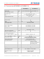
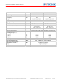
Technical data (M-THERMO 8, M-THERMO 16)........................................................... 52
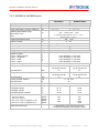
Technical data (M-THERMO2) ...................................................................................... 53
5 µ-THERMO ........................................................................................... 54
5.1
5.2
5.3
5.3.1
5.3.2
5.4
Temperature acqusition with thermocouples ................................................................. 54
Input cable 625-506.xxx................................................................................................. 54
Specific input settings ....................................................................................................55
Break detection..........................................................................................................................55
Averaging...................................................................................................................................55
Technical data................................................................................................................56
6 M-RTD2 ................................................................................................ 57
6.1
6.2
6.3
6.3.1
6.3.2
6.4
Temperature acqusition with RTDs (Pt100)................................................................... 57
Input cable 670-937.xxx................................................................................................. 57
Specific input settings ....................................................................................................58
Scaling .......................................................................................................................................58
Averaging...................................................................................................................................58
Technical data................................................................................................................59
7 M-SENS, M-SENS2, M-SENS 8/8plus................................................. 60
7.1
7.2
7.2.1
7.2.2
Voltage/Current acquisition with sensor excitation ........................................................ 60
Input cable 670-xxx.xxx .................................................................................................61
Input cable 670-807.xxx (M-SENS 4, SIM-SENS) ....................................................................61
Input cable 670-810.xxx (M-SENS 8 / 8plus) ............................................................................61
IPETRONIK Engine Compartment Measurement
IPETRONIK GmbH & Co. KG
ipetronik.com
3/ 92
Content
7.3
7.3.1
7.3.2
7.4
7.4.1
7.4.2
7.4.3
7.4.4
7.4.5
7.5
7.5.1
7.5.2
Input / Principle details...................................................................................................62
Filter in the measurement engineering - Why do we use filters? ..............................................62
Filter in the measurement engineering - How do we use filters? ..............................................63
Extended input settings.................................................................................................. 64
Scaling, measuring range..........................................................................................................64
Sensor, initial excitation.............................................................................................................64
Filter, averaging.........................................................................................................................64
Offset adjust...............................................................................................................................65
Status-LED am Messeingang....................................................................................................65
Technical data................................................................................................................66
M-SENS, M-SENS2...................................................................................................................66
M-SENS 8, M-SENS 8plus ........................................................................................................68
8 Mc-THERMO ........................................................................................ 70
8.1
8.2
8.2.1
8.2.2
8.2.3
8.3
8.3.1
8.3.2
8.4
Voltage and temperature acquisition ............................................................................. 70
Input cable ..................................................................................................................... 70
Input cable 620-644.xxx Mc-THERMO VIN CL Cable open .....................................................70
Input cable 620-645.xxx Mc-THERMO VIN CL Cable Banana .................................................71
Input cable 620-643.xxx Mc-THERMO VIN CL Cable BNC/S ..................................................71
Extended input settings.................................................................................................. 72
Sensor mode .............................................................................................................................72
Break detection and averaging..................................................................................................72
Technical data................................................................................................................72
9 M-FRQ, M-CNT2................................................................................... 74
9.1
9.2
9.3
9.3.1
9.3.2
9.4
9.4.1
9.4.2
9.4.3
9.4.4
9.4.5
9.5
Frequecy- / Cycle acquisition incl. sensor supply .......................................................... 74
Input cable 670-858.xxx................................................................................................. 75
Input / Principle details...................................................................................................76
Measuring method.....................................................................................................................76
Status LED at the input..............................................................................................................77
Extended input settings.................................................................................................. 77
Scaling, measuring ranges ........................................................................................................77
Input signal ................................................................................................................................78
Sensor, initial excitation.............................................................................................................79
Filter...........................................................................................................................................79
Mode (M-CNT2).........................................................................................................................79
Technical data................................................................................................................80
10 MultiDAQ.............................................................................................. 82
10.1
10.2
10.3
10.4
42 Channel multi input device T/ U/ I/ f .......................................................................... 82
Input cable ..................................................................................................................... 82
Create and configure MultiDAQ .....................................................................................82
Technical data................................................................................................................84
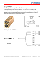
11 CANpressure ....................................................................................... 86
11.1 Pressure sensor with CAN output.................................................................................. 86
11.2 Pressure connections ....................................................................................................86
11.3 Input / Principle details...................................................................................................87
IPETRONIK Engine Compartment Measurement
IPETRONIK GmbH & Co. KG
ipetronik.com
4/ 92
Content
11.4 Extended input settings.................................................................................................. 87
11.4.1 Scaling .......................................................................................................................................87
11.4.2 Filter, averaging.........................................................................................................................88
11.4.3 Adjust.........................................................................................................................................88
11.5 Technical data................................................................................................................89
12 Appendix.............................................................................................. 90
12.1 Linear signal scaling ......................................................................................................90
IPETRONIK Engine Compartment Measurement
IPETRONIK GmbH & Co. KG
ipetronik.com
5/ 92
Important and general information
1 Important and general information
1.1 Important information
Please follow these instructions before and during the use and application on any IPETRONIK
product!
1.1.1 Safety and Warning instructions
Please follow the instructions and information as contained in the user manual!
1. The user can influence an electronic system by applying the IPETRONIK product. This
might cause risk of personal injury or property damages.
2. The use and application of the IPETRONIK product is permitted only to qualified
professional staff, as well as, only in appropriate manner and in the designated use.
3. Before using an IPETRONIK measurement system in the vehicle it has to be verified that no
function of the vehicle, which is relevant for secure operation, might be influenced:
- by the installation of the IPETRONIK measurement system in the vehicle,
- by an potential malfunction of the IPETRONIK system during the test drive.
In order to avoid possible danger or personal injury and property damages, appropriate actions
are to be taken; such actions have to bring the entire system into a secured condition (e.g. by
using a system for emergency stop, an emergency operation, monitoring of critical values).
Please check the following points to avoid errors:
-
Adaption of sensors to components of the electrical system / electronics, brake system,
engine and transmission control, chassis, body.
-
Tap of one or several bus systems (CAN, LIN, ETHERNET) including the required electrical
connection(s) for data acquisition.
-
Communication with the vehicle’s control units (ECUs), especially with such of the brake
system and/or of the engine and transmission control (power train control system).
-
Installation of components for remote data transmission (mobiles, GSM/GPRS modems, WiFi
and Bluetooth components).
4. Before directly or indirectly using the data acquired by an IPETRONIK measurement system
to calibrate control units, please review the data regarding to plausibility.
5. With regard to the application of IPETRONIK products in vehicles during use on public roads the
manufacturer and/or registered user of the vehicle has to ensure that all
changes/modifications have no influence concerning the license of the vehicle or its
license of operation.
6. User does agree to the instructions and regulations as mentioned above. In case the user
does not agree with the instructions and regulations as mentioned above, he has to notify this
expressly and immediately in writing to IPETRONIK before confirming the sales contract.
1.1.2 Liability, Warranty, Copyright, License agreement
Limitation of liability
Any liability of IPETRONIK, its representatives, agents and the like, especially with regard to personal
injury or damage to property of any kind, shall be excluded (within the legally admissible framework), as
far as, the instructions and warnings, as mentioned below, have not been followed.
Warranty
Products, accessories and services have a 24 months warranty.
All product data, specifications, drawings, etc., correspond to the current condition of the indicated
creation date. For the purpose of optimizing technical processes and production, some details of our
modules and accessory components may be modified at any time without prior notification.
IPETRONIK Engine Compartment Measurement
IPETRONIK GmbH & Co. KG
ipetronik.com
6/ 92
Important and general information
Although the present document has been prepared with the utmost attention to detail, it may not be
exempt of misprints, typing or transcription errors. These errors are not covered by any warranty.
Copyright and Duplication
All rights reserved to IPETRONIK GmbH & Co. KG, in particular those of property, copyright and
trademarks. The rights related to any third party trademarks mentioned in the present document remain
unaffected.
This document may not be duplicated, partially or entirely without the prior approval from IPETRONIK
GmbH & Co. KG. All graphics and explanations are copyright protected. Any use beyond the scope of the
document is prohibited.
Software license agreement
This software is property of IPETRONIK GmbH & Co. KG, and is protected by copyright laws. Its total or
partial reproduction is strictly forbidden.
General license agreement
IMPORTANT - READ CAREFULLY! THIS IS A LEGAL AGREEMENT BETWEEN YOU, LICENSEE,
AND IPETRONIK GMBH & CO. KG/IPETRONIK INC. ("IPETRONIK"). BY CHECKING “I ACCEPT ALL
OF THE TERMS CONTAINED IN THE ABOVE AGREEMENT” DURING INSTALLATION, COPYING OR
USING THIS PRODUCT IN ANY WAY YOU ACKNOWLEDGE THAT YOU HAVE READ THIS LICENSE
AND THAT YOU UNDERSTAND AND EXPRESSLY AGREE TO BE BOUND BY THE TERMS AND
CONDITIONS SET FORTH BELOW.
A valid software license is required to use the software.
1. Definitions
a.
SOFTWARE is defined as computer program in object code or machine-readable format,
together with any and all modifications, enhancements, updates, and improvements
provided by IPETRONIK as well as any subsequent versions, corrections, bug fixes,
enhancements, updates or other modifications, regardless of the source. The term
“Licensed Software” shall not include the source code version of the Licensed Software.
b.
EQUIPMENT is defined as automotive measuring equipment produced by IPETRONIK as
well as other parties.
c.
LICENSEE is defined as the recipient of this SOFTWARE and any of its employees, agents
or representatives.
d.
MODIFY or MODIFICATION is defined as change to the SOFTWARE by LICENSEE in
order to customize the SOFTWARE for use solely by LICENSEE.
2. License Terms
a.
As long as LICENSEE complies with all terms in this Software License Agreement
IPETRONIK grants LICENSEE a non-exclusive, non-transferable license to load and use
the SOFTWARE upon the terms and conditions set forth below.
b.
LICENSEE has the right to load the SOFTWARE for use on any internal computer or piece
of EQUIPMENT, as long as it is only on one computer or piece of EQUIPMENT at any
given time.
c.
LICENSEE will notify all of its employees, agents or representatives permitted access to
the SOFTWARE of the duties and obligations under this Software License Agreement.
d.
LICENSEE has the right to MODIFY the SOFTWARE for use on any internal computer or
of EQUIPMENT, as long as it is only on one computer or piece of EQUIPMENT at any
given time.
e.
Any MODIFICATION(S) to the SOFTWARE are subject to the terms and conditions of this
Agreement.
f.
LICENSEE may not:
i.
Loan, rent, lease, give, sublicense, distribute, transmit or otherwise transfer the
SOFTWARE, or otherwise exercise any of IPETRONIK's legal rights in and to the
IPETRONIK Engine Compartment Measurement
IPETRONIK GmbH & Co. KG
ipetronik.com
7/ 92
Important and general information
SOFTWARE, or any derivative works of the SOFTWARE, in whole or in part, except
with the prior written agreement of IPETRONIK.
ii.
Copy, translate, reverse engineer, decompile, disassemble the SOFTWARE, in whole
or in part.
iii.
Except as provided is Section 2(d), create derivative works based on the SOFTWARE,
in whole or in part.
iv. Remove, modify or cause not to be displayed any copyright or trademark notices,
license agreements, or startup messages contained in the programs or
documentation.
v.
Transmit or otherwise export outside of the Unites States any of the SOFTWARE or
technology in violation of United States or other applicable laws or regulations.
3. Ownership of Intellectual Property
LICENSEE agrees and acknowledges that the SOFTWARE is being provided to it only for use
in EQUIPMENT in the ordinary course of business and that LICENSEE agrees and
acknowledges that IPETRONIK is the owner of all title and proprietary rights in the
SOFTWARE, including, without limitation, any and all patents, copyrights, trademarks or any
other intellectual property rights associated with it under the laws of the United States or any
jurisdiction throughout the world. No right, title or interest in the SOFTWARE or any IPETRONIK
patent, copyright, trademark, or any other intellectual property right is transferred to LICENSEE
or any other party through this Software License Agreement.
4. Disclaimer of Warranties; Liability Limitations
a.
THE SOFTWARE IS PROVIDED TO YOU "AS IS". THERE ARE NO WARRANTIES OF
ANY KIND, WHETHER EXPRESS OR IMPLIED, INCLUDING BUT NOT LIMITED TO THE
WARRANTIES OF MERCHANTABILITY, FITNESS FOR A PARTICULAR PURPOSE AND
COMPATIBILITY, AND TITLE.
b.
LICENSEE ASSUMES ALL RISK AS TO THE SELECTION, USE, PERFORMANCE AND
QUALITY OF THE SOFTWARE. IN NO EVENT WILL IPETRONIK OR ANY OTHER
PARTY WHO HAS BEEN INVOLVED IN THE CREATION, PRODUCTION OR DELIVERY
OF THE SOFTWARE BE LIABLE FOR SPECIAL, DIRECT, INDIRECT, INCIDENTAL OR
CONSEQUENTIAL DAMAGES, INCLUDING LOSS OF PROFITS OR INABILITY TO USE
THE LICENSED MATERIAL. IN NO EVENT SHALL IPETRONIK'S LIABILITY FOR ANY
DAMAGES OR LOSS TO LICENSEE OR TO ANY THIRD PARTY EXCEED ANY
LICENSE FEE ACTUALLY PAID BY THE LICENSEE TO IPETRONIK FOR THE
SOFTWARE.
c.
Since some states or jurisdictions do not permit the exclusion of implied warranties or
limitation of liability for consequential damages, in such states or jurisdictions, the liability is
limited to the fullest extent permitted by law.
5. Intellectual Property Infringement Indemnification
a.
IPETRONIK shall defend, indemnify, and hold LICENSEE harmless from and against any
claims and fees (including attorneys’ fees), damage awards arising in connection with a
claim that the licensed SOFTWARE or documentation, when properly used, infringes upon
any presently existing, valid and enforceable United States patent, trademark, or other
intellectual property right, provided that:
i.
such claim of infringement is not based on any Modification or action taken or suffered
by LICENSEE other than the use of the licensed SOFTWARE and documentation in
accordance with the terms and conditions of this agreement;
ii.
such claim of infringement is not based on any action by LICENSEE in modifying the
SOFTWARE pursuant to the terms of Section 2(d).
iii.
LICENSEE promptly notifies IPETRONIK of such claim in writing at
[email protected], and gives IPETRONIK exclusive control over the defense and
settlement of such claim;
iv.
LICENSEE provides such cooperation and assistance, at IPETRONIK’S expense, as
IPETRONIK may reasonably request to settle or oppose any such claim; and
IPETRONIK Engine Compartment Measurement
IPETRONIK GmbH & Co. KG
ipetronik.com
8/ 92
Important and general information
v.
b.
c.
such claim of infringement is based only on the licensed SOFTWARE and
documentation as provided to LICENSEE.
In the event of any infringement claim for which IPETRONIK is liable pursuant to section 5
(a), IPETRONIK may, at its sole option and expense:
i.
procure for LICENSEE the right to continue using the licensed SOFTWARE or
documentation;
ii.
modify or amend the licensed SOFTWARE or documentation so that it becomes noninfringing;
iii.
replace the licensed SOFTWARE or documentation with a non-infringing substitute; or
iv.
recover the infringing licensed software and documentation from LICENSEE and
repay to LICENSEE all license fees paid to IPETRONIK in connection therewith, less
a reasonable amount based on LICENSEE’s use prior to such recovery and refund.
This Article 5 sets forth IPETRONIK’s sole obligations and liability for intellectual property
infringement. These indemnity provisions only apply to the SOFTWARE as originally
licensed to LICENSEE and do not cover any MODIFICATIONS made by LICENSEE or any
other third party.
6. Limitation of Liability
a.
EXCEPT WITH RESPECT TO ITS INTELLECTUAL PROPERTY INDEMNIFICATION
OBLIGATIONS, AS SET FORTH IN ARTICLE 5, IN NO EVENT SHALL IPETRONIK BE
LIABLE FOR SPECIAL, INDIRECT OR CONSEQUENTIAL DAMAGES (INCLUDING,
WITHOUT LIMITATION, LOST PROFITS, LOST DATA, OR LOST SAVINGS), EVEN IF
IPETRONIK WAS ADVISED OF THE POSSIBILITY OF SUCH DAMAGES.
FURTHERMORE, IPETRONIK’S LIABILITY (WHETHER IN CONTRACT, TORT, OR
OTHERWISE) ARISING OUT OF, OR CONNECTED WITH, THIS AGREEMENT OR THE
LICENSED SOFTWARE OR DOCUMENTATION SHALL IN NO CASE EXCEED THE
PAYMENTS RECEIVED BY IPETRONIK FROM LICENSEE FOR THE LICENSED
SOFTWARE AND DOCUMENTATION.
b.
EXCEPT IN CONNECTION WITH ITS OBLIGATIONS UNDER ARTICLE 5:
i.
IN NO EVENT SHALL LICENSEE BE LIABLE FOR SPECIAL, INDIRECT OR
CONSEQUENTIAL DAMAGES (INCLUDING, WITHOUT LIMITATION, LOST
PROFITS, LOST DATA, OR LOST SAVINGS), EVEN IF LICENSEE WAS ADVISED
OF THE POSSIBILITY OF SUCH DAMAGES; AND
ii.
LICENSEE’S LIABILITY (WHETHER IN CONTRACT, TORT, OR OTHERWISE)
ARISING OUT OF, OR CONNECTED WITH, THIS AGREEMENT OR THE
LICENSED SOFTWARE OR DOCUMENTATION SHALL IN NO CASE EXCEED THE
PAYMENTS OWED TO LICENSOR FOR THE LICENSED SOFTWARE AND
DOCUMENTATION.
7. Indemnification Obligations of LICENSEE
a.
LICENSEE shall defend, indemnify, and hold IPETRONIK harmless from any claims,
losses, expenses, fees (including attorneys’ fees), costs or damages arising in connection
with a MODIFICATION or LICENSEE’S unauthorized use of the Licensed Software or
Documentation.
8. Merger Clause
a.
LICENSEE agrees that this Software License Agreement is the complete and exclusive
agreement between LICENSEE and IPETRONIK governing the SOFTWARE. This
Software License Agreement supersedes and merges all prior agreements with
IPETRONIK concerning the SOFTWARE and can only be modified by a subsequent
written agreement signed by IPETRONIK. To the extent that there is any conflict between
this Software License Agreement and any IPETRONIK purchase order or other written
agreement for the purchase of IPETRONIK parts or products, the terms of the purchase
order or written agreement control.
IPETRONIK Engine Compartment Measurement
IPETRONIK GmbH & Co. KG
ipetronik.com
9/ 92
Important and general information
9. General
a.
If any provision or portion of a provision of this Software License Agreement is determined
to be invalid or unenforceable, it shall be deemed omitted and the remaining provisions of
this Software License Agreement shall remain in full force and effect to the fullest extent
permitted by law.
b.
LICENSEE may not assign or transfer all or part of this Software License Agreement to any
third party without the express written approval of IPETRONIK.
c.
This Software License Agreement will be governed by the laws of the State of Michigan
without regard to its conflict of laws provisions.
d.
All disputes arising out of, or in connection with, the present contract shall be finally settled
under the Rules of Arbitration of the International Chamber of Commerce by one or more
arbitrators appointed in accordance with the said Rules.
1.2 General information
1.2.1 About this manual
The manual describes the structure of the IPEmeasue CAN-Bus devices M-THERMO2, M-THERMO
8/16, Mc-THERMO, µ-THERMO 8, M-RTD2, M-SENS2, M-SENS 4/8/8plus, M-CNT2, M-FRQ, MultiDAQ
and CANpressure, as well as, peripheral devices and accessories.
1.2.2 Version
Handbuch Motorraum-Messtechnik
This manual has the version number 01.09.00, released October 2013 © All rights reserved !
IPEmotion PlugIn IPETRONIK CAN
Contents described in this document relates to the current release version 01.09.
IPEmotion
Contents described in this document relates to the release versions 01.06. to 3.01.00
To run this PlugIn an IPEmotion release ≥ V02.00 has to be installed on your computer.
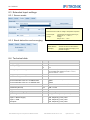
1.2.3 Legend of used icons
Tip
This icon indicates a useful tip that facilitates the application of the software.
Information
This icon indicates additional information for a better understanding.
Attention!
This icon indicates important information to avoid potential error messages.
IPETRONIK Engine Compartment Measurement
IPETRONIK GmbH & Co. KG
ipetronik.com
10/ 92
Important and general information
1.2.4 Support
Headquarter:
IPETRONIK GmbH & Co. KG
Im Rollfeld 28
76532 Baden-Baden, Germany
Phone +49 72 21 99 22 0
Fax +49 72 21 99 22 100
[email protected]
www.ipetronik.com
Limited commercial partnership with its head office in Baden-Baden, registry court HRA No. 201313
IPETRONIK Verwaltungs-GmbH Baden-Baden is an individually liable society, registry court Mannheim
HRB No. 202089
CEOs: Erich Rudolf, Andreas Wocke
Technical support and product information
www.ipetronik.com
E-Mail: [email protected]
1.2.5 Related documentation
IPEmotion
The documentation IPEmotion.pdf provides you with a description and useful information related to
IPEmotion. This documentation is stored in the following standard language dependent directory:
C:\Program Files (x86)\IPETRONIK\IPEmotion Vxx.xx.xx\Help.
1.3 Documentation feedback
At IPETRONIK, the technical publications team strives to produce documentations of the highest quality
and values your feedback as a reader and user. If you have any comments or suggestions regarding our
product manuals, contact us under [email protected] .
When commenting on our products, please include the following information:
Version number
Name of the guide
Page number or section title
Brief description of the content (e.g. inaccurate instructions, grammatical errors, or information
that require clarification)
Any suggestions for a general documentation improvement
IPETRONIK Engine Compartment Measurement
IPETRONIK GmbH & Co. KG
ipetronik.com
11/ 92
General system
2 General system
2.1 Modular system structure
IPETRONIK Engine Compartment Measurement contains devices of the M2 series (M-THERMO2,
M-RTD2, M-SENS2, M-CNT2) and the M series (M-THERMO, M-SENS, M-FRQ, Mc-THERMO), µTHERMO, as well as, CANpressure. Each device is an independent acquisition system and can be used
as a stand-alone devices, as well as, in combination with other devices (also with SIM series devices) in a
CAN bus network. The signals (Temperature, Voltage, Current, Pressure) are detected by using
corresponding inputs, are digitized as 16 bit sign and output as CAN message on the CAN bus. Each
devices has 4 or 8 inputs depending on the design.
CANpressure is a 1-channel pressure sensor with integrated acquisition electronics including a CAN
controller. The acquired pressure, as well as, the temperature of the pressure tap are directly output as a
CAN signal.
The configuration of all parameters takes place by using IPEmotion and a PC/Notebook with CAN
interface (e.g. PCMCIA CAN card or USB-CAN-Interface). IPEmotion, as well as, software applications by
different providers can be used for acquiring the signals as CAN message.
An alternative to the Windows PC system is the use of devices or device combinations with an
IPETRONIK data logger (M-LOG, S-LOG, FLEETlog, IPElog).
IPETRONIK Engine Compartment Measurement
IPETRONIK GmbH & Co. KG
ipetronik.com
12/ 92
General system
2.2 Connecting the devices via the CAN-Bus
2.2.1 Basics of CAN-Bus
CAN-Standard
The communication of the IPETRONIK SIM and M devices takes place by using the CAN bus according
to the CAN 2.0 A (11 Bit Identifier) and CAN 2.0 B (29 Bit Identifier) specification. Each software
application, which is able to detect CAN data via a suitable interface, can detect the device data and
process. Examples: CANalyzer, INCA, DIAdem, LabVIEW. The device configuration takes place by using
the CAN bus and the IPETRONIK configuration software.
Structure of a CAN message
User data within the CAN
message:
Maximum 8 values in the byte
format or 4 values (4 channels) in
the Word format can be
transferred depending on the
CAN message.
recessive
Remoteframe CAN 2.0A (11 Bit Identifier)
Start
1 Bit
Identifier
11 Bits
RTR IDE r0
1 Bit 1 Bit 1 Bit
DLC
4 Bit
CRC
15 Bit
Data
0..8 *8 Bit
ACK
2 Bit
EOF + IFS
10 Bit
Data
0..8 *8 Bit
CRC
15 Bit
recessive
Remoteframe CAN 2.0B (29 Bit Identifier)
Start
1 Bit
Identifier
11 Bits
SRR IDE
1 Bit 1 Bit
Identifier
18 Bits
RTR r1 r0
1 Bits 1 Bit 1 Bit
DLC
4 Bit
ACK
2 Bit
EOF + IFS
10 Bit
CAN 2.0A (11 Bit Identifier)
CAN 2.0B (29 Bit Identifier)
Bits
Description
Bits
1
SOF
Start of Frame
1
SOF
Start of Frame
11
ID
Identifier
11
ID
Identifier
1
SRR
1
1
IDE
Identifier Extension (0)
RTR
1
r0
4
DLC
Remote Transmission Request
Description
1
IDE
Identifier Extension (1)
18
ID
Identifier (extended)
1
RTR
Remote Transmission Request
1
r1
1
r0
Number of following data bytes
4
DLC
Number of following data bytes
64
Data
Data bytes
64
Data
Data bytes
15
CRC
Error Identification Code
15
CRC
Error Identification Code
2
ACK
Acknowledge
2
ACK
Acknowledge
10
EOF
End of Frame
10
EOFS
End of Frame
Summe
130
110
Word
0
1
2
3
Byte
0
1
2
3
4
5
6
7
Summe
Bit (Message layout in the displaying format „Intel Standard“)
7
15
23
31
39
47
55
63
6
14
22
30
38
46
54
62
IPETRONIK Engine Compartment Measurement
5
13
21
29
37
45
53
61
4
12
20
28
36
44
52
60
3
11
19
27
35
43
51
59
2
10
18
26
34
42
50
58
IPETRONIK GmbH & Co. KG
1
9
17
25
33
41
49
57
ipetronik.com
0
8
16
24
32
40
48
56
13/ 92
General system
Access to the CAN-Bus, Transferring properties
The CAN bus allows a safe and effective data transfer of the connected devices (non-destructive bitwise
arbitration = resource distribution to different devices). The CAN bus is therefore used as a standard
communication medium in the automotive area and the industrial automation.
The most important characteristic CAN bus properties are:
Every bus participant (node) can send, as well as, receive.
First of all, the node, which wants to send, needs the authorization. All participants become
automatically a recipient (There is no abortion of the data sending process > non-destructive
collision).
No stations are addressed but messages.
Every message is characterized by its name (Identifier).
The less the identifier, the higher the message priority.
A message can transport up to 8 * 8 Bit = 64 Bit (8 Byte) user data, whereas each message requires
110 Bit or 130 Bit (Extended ID).
Depending on the hardware and the bus line length, up to 1 MBit/ s can be transferred.
The following important conclusions result from the properties above:
The less the bus load, the less the probability of a “Bus access conflict” (you can call this a real-time
capable area).
A high bus load forces stations to loose messages with a high identifier or to send them more slowly.
Messages with a high identifier can “get lost”.
Not sent messages are only registered by the “Recipient node” because data are missing. If no
timeout has been defined, the last valid value is generally sent, i.e. a mistakenly constant value.
Transfer rate, Bus line length
The CAN bus supports a max. transfer rate of 1 MBit/s according to Norm ISO 11898-2.
This value is limited in practice by the following points:
the bus line length
the branch line length to the CAN stations
the bus lines quality and the plug contacts
the bus line design (twisted, single or two-wire bus)
bus connection structure and
type and strength of external perturbations
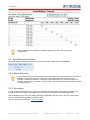
Example
Data rate on the bus
Data length of a CAN message
User data in a message
Time for a CAN message
Calculating the total sampling rate
Converted to one channel
Theoretical transfer rate
Practical experiences
1 MBit/s = 1 µs/Bit
130 Bits gesamt
64 Bit = 4 values with 16 Bit resolution each
130 Bit x 1 µs/Bit = 130 µs/message, i.e. 4 values require 130 µs
130 µs match 7.69 kHz
4 x 7.69 kHz = 30.76 kHz
30 channels with 1 kHz = 30 kHz
26 channels with1 kHz = 26 kHz
The value is lower at guaranteed synchronity.)
If CAN messages are not completely used (e.g. only three 16 bit values instead of four per message),
less data can be transferred although the sum sampling rate has not yet reached the maximum. This also
applies if different sampling rates are defined in one system, because the data division to the CAN
messages is not time-optimized (minimum time required).
IPETRONIK Engine Compartment Measurement
IPETRONIK GmbH & Co. KG
ipetronik.com
14/ 92
General system
2.2.2 Ampacity and voltage drop
Besides the fact that the max. bus line length is defined by the desired data transfer rate, the ampacity
and the voltage drop in the system have primarily to be checked. This is especially important for systems
with a high number of devices and/or long connections lines of the devices (e.g. distributed systems with
connection lines of 3 m (9.84 ft) and more between the device groups). Additional actions should be taken
accordingly to the situation.
Ampacity
The maximum current via the M-CAN system cables (e.g. 620-560.xxx) is 4 A (heat generation by
transition resistances of the plug contacts).
The system capacity and therefore the power consumption can approximately be calculated by using the
number of devices (including the sensor supply). A direct power acquisition in the real system provides
exact values.
We recommend one or several of the following actions if the limit value is exceeded:
Increasing the supply voltage of the devices (e.g. 24 V DC power supply or 42 V DC
instead of 12 V)
Centered voltage supply via T connection or as close as possible to the devices with high
requirements (rather than at the beginning or end of the system chain)
power
Additional system supply via a T connection at a suitable position
Voltage drop
Even if the limit value for the ampacity is not reached, long lines in an extensive system can cause
perturbations in the acquisition process. This mainly applies to devices at the end of the system chain,
because the voltage of the last devices does not exceed the input threshold of 9 V (due to a high voltage
drop in the system).
We recommend one or several of the actions mentioned above.
The voltage drop can be calculated by using the following formula:
U=RxI
R = 2 x RCable [Ω/m] x LengthCable [m]
I = PDevices [W] / VDevices [V]
For estimating the voltage drop, a resistance of
50 mΩ/m for the M-CAN cables and
35 mΩ/m for the SIM-CAN cables
can be used including the transition resistances of the plug contacts. Systems, which are in the limit
range of the voltage drop, should be controlled in individual cases. To do so, our support will be pleased
to assist you.
As the power consumption of a device depends on the supply voltage, it is useful to calculate the voltage
drop from the chain end to the feeding point. In this case, a minimum voltage of 9 V is set to the last
device and the required excitation is calculated. The calculated value should be generously rounded
upwards for guaranteeing a safe operation.
Another fact is the variable internal resistance of the input power supplies (low excitation = lower internal
resistance).
In practice, this means: If the net excitation decreases (e.g. because of a weak power supply or a high
resistivity with long cables), the devices have to readjust to cover the current power requirements. This
causes a higher power consumption, which additionally increases the voltage drop.
IPETRONIK Engine Compartment Measurement
IPETRONIK GmbH & Co. KG
ipetronik.com
15/ 92
General system
2.3 Synchronous data acquisition
2.3.1 Principle of the synchronous signal acquisition
Every device has an internal clock, which guarantees an equidistant signal acquisition, i.e. the sampling
of the momentary values of the continuous signal takes place in identical intervals. This clock
synchronizes the A/D conversion of all channels within a device, but not the channels of other devices in
the system. The clocks of every device have no reference to each other and differ regarding the clock
frequency and phase shifting. Reasons for that are components and manufacturing tolerances, as well
as, different environmental conditions.
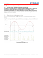
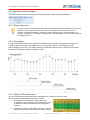
2.3.2 Master clock as higher system clock
To counteract those disadvantages, a single system clock for all devices (Synchronization clock) is
required.
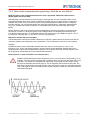
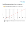
The graphic shows that signals with a high sampling rate, as well as, signals with a low sampling rate are
always synchronously detected. This guarantees an simultaneous acquisition of values, which are stored
at one date.
IPETRONIK Engine Compartment Measurement
IPETRONIK GmbH & Co. KG
ipetronik.com
16/ 92
General system
2.3.3 Measurement systems without master clock
The non-synchronous acquisition seriously influences the comparability and therefore the plausibility of
the acquisition – especially at long-term acquisitions. The time variation of the single clock generators
sums with the acquisition time, i.e. the longer the acquisition the higher the deviation. If the frequency
deviation and the drift direction of the different clocks is unknown, you cannot assume that all values,
which are assigned to a specific value at the time axis, did really exist at that moment.
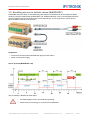
2.3.4 IPETRONIK measurement system with/without synchronization clock
These cables offer besides the
voltage supply and the CAN bus
additional wires for the 2 kHz
synchronization signal.
IPETRONIK Engine Compartment Measurement
IPETRONIK GmbH & Co. KG
ipetronik.com
17/ 92
General system
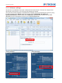
2.3.5 Software settings
The devices in the standard mode (clock = free) work with internal clocks. The user can configure if the
devices are synchronously or non-synchronously detecting the signals.
The synchronous data acquisition is activated with the property of the corresponding bus system by using
the main navigation point Signals within the CAN bus system IPETRONIK-1 ► Options ►
Synchronized mode (or via the context menu Properties). IPEmotion sets one device as the clock
generator and the remaining devices are set to the synchronized clock.
System properties
IPETRONIK Engine Compartment Measurement
Device properties
IPETRONIK GmbH & Co. KG
ipetronik.com
18/ 92
General system
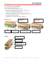
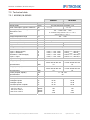
2.4 General device description
2.4.1 Properties and structure
The devices have the following properties in common:
different channel sampling rates, depending on the device up to 2 kHz
all channels are completely electrically isolated
output of the 16 bit data on the CAN bus according to ISO 11898-2
extended operating temperature range (-40 °C to +125 °C / -40 F to + 257 F)
very compact case in IP67 protection
dovetail guide for connecting M series devices without tools
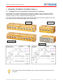
Dovetail guide for
connecting devices
without tools
M-Series modules
Input female
connectors
µ-THERMO
LED for the
operating status
Sockets for the CAN bus
and the power supply
Anodized aluminium
case (IP 67) with
mounting holes
LED for the input
status
Anodized aluminium
case (IP 67)
LED for the
operating status
Sockets for the CAN bus
and the power supply
Input female
multi connector
IPETRONIK Engine Compartment Measurement
IPETRONIK GmbH & Co. KG
ipetronik.com
19/ 92
General system
CANpressure
LED for the
operating status
Sockets for the CAN bus
and the power supply
Stainless steel case
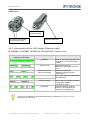
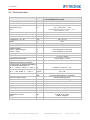
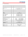
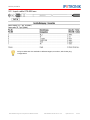
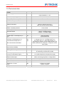
2.4.2 Interpretation of the LED display (flashing codes)
M-THERMO, µ-THERMO , M-SENS, M-FRQ, MultiDAQ, CANpressure
LED display
(intervals in seconds)
0.9
0.1
0.25
0.5
0.1
0.9
0.9
0.25
0.25
0.5
0.1
0.25
0.25
0.5
0.1
0.9
0.25
Mode
Meaning
Operation
Ready for use or data transfer to the
configuration (no measuring data
transfer)
Measurement running!
Operation in system with a master
device
Measurement running!
Operation in system without a
master device
Error, which requires a restart (PWR
OFF/ PWR ON)
System mode
Freerunning mode
(also synchronized)
0.25
0.5
Error
Download kernel
Download
Device ready for firmware download
(only at initial update or
manufacturer reset)
Firmware download, flashing
frequency corresponds to the
transfer of the program lines
The LED color depends on the ambient temperature. Temperatures > 100 °C / 212 °F
change the color to yellow.
IPETRONIK Engine Compartment Measurement
IPETRONIK GmbH & Co. KG
ipetronik.com
20/ 92
General system
Mc-THERMO, M-THERMO2
Mc-THERMO und M-THERMO2 verfügen über eine Mehrfarben- Status-LED, dadurch unterscheidet sich
die LED-Anzeige von den oben genannten Modulen.
LED display
(intervals in seconds)
0.1
0.9
0.1
0.9
Mode
Meaning
Operation
Ready for use or configuration data transfer
(no measuring data transfer)
Freerunning mode Measurement running!
(also synchronized)
Error
0.5
0.5
0.5
0.5
Serious error happend during configuration,
measurement initialization or communication
CAN error
Init error
Error in CAN bus communication
Error in basic initialization of the module,
Current configuration does not match to to
the device firmware.
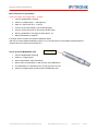
2.4.3 Reverse polarity protection
All M devices have an electronic reverse polarity protection and an additional inrush current limitation.
The reverse polarity protection shields the complete excitation range of the corresponding device and
avoids damages due to lines changing PWR+ (red) and PWR GND (black).
The inrush current limitation avoids too high inrush currents, which reduce the durability of switches and
relays contacts and avoids the burning of the plug contacts if cables of the power supply are plugged
under tension.
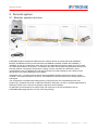
2.5 Cables
In order to electrically connect the devices, as well as, the sensors, cables with different lengths and
various plug configurations are available:
System cable
Connect the devices at the CAN bus and contain the data lines (CAN bus and synchronization lines), as
well as, the power supply.
I/O cable
Connect the device input with the respective sensor. The cables are open ended with lengths of 3 m, 6 m,
and 10 m (9.84/ 19.68/ 32.8 ft).
Cable number
The cable part number identifies the cable type and length, e.g.:
620-502.030
Cable series
(e.g. M-CAN)
Consecutive
number
IPETRONIK Engine Compartment Measurement
Length in dm 030 =
30 dm = 3 m
IPETRONIK GmbH & Co. KG
ipetronik.com
21/ 92
General system
2.6 Mechanical accessories
2.6.1 Differences of the M design
The extension of the M series by the new M-THERMO 16 and M-SENS 8 devices requires new
connection mechanics to meet the higher practice demands. The new devices are exclusively available in
the 2nd version of the dovetail mechanics (identification BR). The existing devices M-THERMO 8, MSENS 4 and M-FRQ are available in the 1st version, as well as, in the 2nd version of the connection
mechanics. A mechanical compatibility between the devices is guaranteed at using corresponding
adapters. If the devices of the same version are connected, only one adapter is required as a bridge
between both connecting systems.
M case V1 (horizontal)
Longitudinal nut and dovetail
(horizontal)
Holes for screw mounting
Top, rear view
Bottom, rear view
M case V2 (BR)
Transverse nut and dovetail
(vertical)
optional: lateral mounting of
the brackets
Longitudinal groove for IPErack
Top, rear view
Bottom, rear view
2.6.2 Mounting brackets for M case Version 2 (BR) and M2 case
The brackets are used for the screw fastening of the devices with new connection mechanics. Each
device requires 2 brackets, which allow different mounting positions.
MOD-M-HWI-100
IPETRONIK Engine Compartment Measurement
IPETRONIK GmbH & Co. KG
ipetronik.com
22/ 92
General system
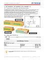
2.6.3 Mounting brackets for M-THERMO2
MOD-M-TH2-HWI-1
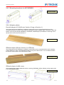
2.6.4 Adapter plates
Dovetail adapter V1/V2 (M case Version 2 long at Version 1)
The existing devices M-THERMO 8, M-SENS 4 and M-FRQ can be connected with devices of the
connection mechanics version 2 (only long case design) by using an adapter plate. This plate is slid at the
bottom of the long M case (M-THERMO 16, M-SENS 8, M-SENS 8plus) and allows the mounting of 2 M
devices each in the short case version V1.
MOD-M-ADAPT-100
IPErack adapter (M case Version 1 at IPErack)
The existing devices M-THERMO 8, M-SENS 4 and M-FRQ can be connected with the quick assembly
system IPErack by using a dovetail adapter plate for fixing to the device back. You can therefore fasten
the devices without tools to the IPErack device plate.
MOD-M-ADAPT-200
IPErack adapter for M2 cases
The Dovetail adapter plate enables M2 device mounting (THERMO2, RTD2, SENS2, CNT2) without tools
to the IPErack device plate.
MOD-M2-ADAPT-1
IPETRONIK Engine Compartment Measurement
IPETRONIK GmbH & Co. KG
ipetronik.com
23/ 92
General system
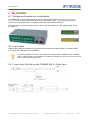
2.6.5 µ-THERMO snap-in fastener
MOD-SNP-HWI-900
The µ-THERMO snap-in fastener allows the combination of µ-THERMO devices without tools in
horizontal, as well as, in vertical order. Each device requires a snap-in fastener.
IPETRONIK Engine Compartment Measurement
IPETRONIK GmbH & Co. KG
ipetronik.com
24/ 92
General system
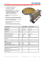
2.6.6 IPErack, quick assembly system for M-Series devieces
Carrier system containing two
exchangeable device plates
2 different sizes available
per device plate up to: ( ) = small design
- 20 (10) devices of the M-THERMO 8,
M-SENS 4 or M-FRQ type
or
- 10 (5) devices of the M-THERMO 16
or
M-SENS 8 / M-SENS 8plus type
Mixed mountings of the listed devices
possible
Use of devices without a dovetail connection at
the back by using mechanical adapter plates
Safety pins on both sides avoid the accidental
extraction of the device plates
Robust carrier system and device plates out
of milled aluminum
Different transfer and elongated mounting
holes for fastening the system at the location.
Carrier system
Basic plate
Length/Width
Side plate
Length/Width
Basic plate, Side plate
Thickness
Height carrier system
without/with device plates
Weight carrier system
without device plates
with two device plates
Material
Slide-in for device plates with two safety
pins each
IPEcrack 20/40
IPEcrack 10/20
mm
522 / 180
302/ 180
mm
237 / 124
237 / 124
mm
10
10
mm
247 / 302
247 / 302
g
g
2180
1800
5480
3600
Aluminum, black anodized
2
2
Pcs.
Device plate with carrying handle
Width
Height
Top without handle
Top with handle
Thickness (without/with guide)
Mass
Material
Maximum mounting
M-THERMO 8, M-SENS 4, M-FRQ and
mixed mountings
Maximum mounting
M-THERMO 16, M-SENS 8 / 8plus and
mixed mountings
Big plate
Small plate
mm
454
234
mm
mm
mm
g
Pcs.
242
242
292
292
8 / 10
8 / 10
1650
900
Aluminum, golden brown hard-coated
20 (per plate)
10 (per plate)
Pcs.
10 (per plate)
IPETRONIK Engine Compartment Measurement
5 (per plate)
IPETRONIK GmbH & Co. KG
ipetronik.com
25/ 92
General system
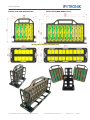
IPErack 10/20 (MOD-IPERACK-003)
IPErack 20/40 (MOD-IPERACK-001)
All dimensions stated in millimeters (mm)
IPETRONIK Engine Compartment Measurement
IPETRONIK GmbH & Co. KG
ipetronik.com
26/ 92
General software description
3 General software description
3.1 Requirements
Further requirements besides the hardware:
Notebook with CAN interface
(e.g. IPEcan, ... ) or
PC with CAN interface
(e.g. IPEcan, ... ) or
M-LOG, S-LOG, FLEETlog or IPElog
(IPETRONIK data logger with real-time operating system)
The IPEmotion software for configuring the device and for acquiring the data via the CAN bus.
The CAN interface must be installed correctly. See the respective manufacturer’s manual for
further information.
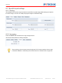
3.2 Supported CAN interfaces
Select the CAN system (e.g. IPETRONIK-1) and choose the CAN hardware tab for listing the supported
CAN interfaces.
IPETRONIK Engine Compartment Measurement
IPETRONIK GmbH & Co. KG
ipetronik.com
27/ 92
General software description
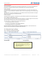
3.3 Configuration with IPEmotion (general)
You can find a detailed description of IPEmotion in the manual, which can be opened in the software as a
PDF.
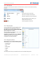
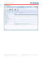
3.3.1 Main dialog
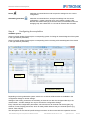
After the start of IPEmotion, the following screen appears.
IPEmotion automatically detects all available hardware connections at starting.
If you want to reduce the required time, select Options > PlugIns for deactivating those
interfaces, which are not used.
Quick Access Bar
Main Navigation Tabs
Main window at selected tab „Project“
Message window
IPETRONIK Engine Compartment Measurement
IPETRONIK GmbH & Co. KG
ipetronik.com
28/ 92
General software description
3.3.2 The title bar
The title bar contains the quick access bar, the software name, as well as, a tool bar with the following
functions:
Minimize the Ribbon
Ctrl+F1
Only show tab names on the ribbon
Help
F1
Open the documentation IPEmotion.pdf
Minimize
Minimize the application window of IPEmotion
Maximize
Make the application window visible on your
desktop and refit the prior size
Close
Close the application of IPEmotion
3.3.3 The file menu
Click on the File button to open the application menu.
The application menu contains basic functions as:
New, Open, Save, Save As, Runtime version, Print
and Close, as well as, further properties such as View,
Options, Support file and About.
The right partial view of the application menu contains
a list of the recently used projects.
The View function contains the menu points Message
window and the Reset command. Show or hide the
message window and reset the displaying
configuration to the default parameters.
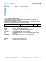
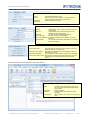
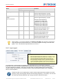
3.3.4 Using the options
With the Options entry, you have the ability to edit user
defined settings. You can define the following options:
Frequently used
Basic settings
View
Data manager
Analysis
Units
PlugIns
The following section offers you a detailed overview over the available setting options.
IPETRONIK Engine Compartment Measurement
IPETRONIK GmbH & Co. KG
ipetronik.com
29/ 92
General software description
Frequently used
Activate or deactivate Start with the latest configuration and define the settings for the automatic
hardware detection. Activate or deactivate the automatic hardware detection at start of IPEmotion
and select a possible standard command after successful detection:
Guided configuration
Automatic configuration or
Manual configuration
Basic settings
Select a preferred configuration type:
Hardware configuration
Signals configuration
Activate or deactivate the options: Accurate acquisition chain required and Expert mode.
View
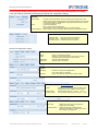
Define your view settings according the following listed points:
Language selection
Skin selection
Displaying tooltips
Font size of the visual elements
Transparency of configuration dialogs (0 – 30 percent),
Activate or deactivate the use of the Windows standard dialogs for the file and directory selection.
The Open file dialog is skin-enabled, i.e. it is shown in the selected user interface type.
IPETRONIK Engine Compartment Measurement
IPETRONIK GmbH & Co. KG
ipetronik.com
30/ 92
General software description
Data manager
Define the Time channel format as Relative or Absolute (This setting is currently not supported for the
export into external formats!) and activate or deactivate the option: Merge time channels with equal
acquisition rate.
Analysis
Select the points per diagram graph. Define if all signals are considered in the analysis diagrams at
drawing the graph or only the samples. Move the bar accordingly to the preferred speed or quality.
Units
Get an overview according the common physical values and their respective unit and edit them.
IPETRONIK Engine Compartment Measurement
IPETRONIK GmbH & Co. KG
ipetronik.com
31/ 92
General software description
PlugIns
Activate or deactivate the hardware systems to be used.
This PlugIn is for all IPETRONIK
CAN bus devices.
With the Settings button, you have the ability to define the components (module type and priority, e.g.
for the type selection of the Dry configuration) of the respective hardware system and to edit additional
options settings.
The selection of the hardware components for the configuration by using a signal library is based on the
Priority. This preselection with a priority assignation of the system components facilitates the device
selection and improves the system speed.
The High priority defines a preferred use of the corresponding hardware component at configuring with a
signal library. The hardware components, which are defined with the Not used priority, cannot be
selected for an acquisition.
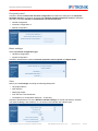
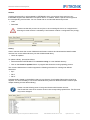
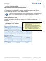
3.3.5 Creating a support file
Enter in the appearing Create support file screen an error description. Accept the
default location for the file. To select another location click on the
symbol.
After you have specified the location and a user defined file name, click Save to
return to the Create support file screen.
After clicking on OK a zip file is generated that contains the error description, as well
as, the following information:
System information (Windows version, computer name, free memory on the local
drives, …)
Current configurations (acquisition, online view, script configurations)
Trace files (.NET, C++)
IPETRONIK Engine Compartment Measurement
IPETRONIK GmbH & Co. KG
ipetronik.com
32/ 92
General software description
If you have any problems while working with IPEmotion, send us this support file at
[email protected].
3.3.6 The quick access bar
The quick access bar is integrated in the title bar and contains functions that are frequently used. Each of
these functions is displayed as an icon.
New
Ctrl+N
Create a new configuration
Open
Ctrl+O
Open an already existing configuration
Save
Ctrl+S
Save the actual configuration
Save as
Save the actual configuration under a new name
Generate
Automatically generating an new configuration with
the actual connected devices
Quick print
Directly printing on the standard printer
Cut
Ctrl+X
Cut the currently selected elements
Copy
Ctrl+C
Copy the selected elements into the clipboard
Paste
Ctrl+V
Add elements from the clipboard
Paste behind
Paste elements from the clipboard behind
Copy to file
Copy the currently selected elements to a file
Paste from file
Add elements from a file
Delete
Delete the selected elements
Clean
Delete all subordinate elements
Undo
Ctrl+Z
IPETRONIK Engine Compartment Measurement
Undo the last step(s)
IPETRONIK GmbH & Co. KG
ipetronik.com
33/ 92
General software description
Redo
Ctrl+Y
Redo undone actions
Properties
Open the configuration dialog
Options
Show/edit general IPEmotion options
Help
F1
The online help will be opened
About
Show information about IPEmotion (edition, license,
options)
3.3.7 The main navigation tabs
The main navigation tabs allow a quick activation of the different main functions of IPEmotion. A tab
displayed in light blue indicates an active function.
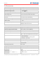
IPEmotion is designed to follow the main navigation tabs from left to right. Use this reasonable order like
a read thread, which guides you step-by-step to a successful acquisition.
Project
Signals
Acquisition
View
Data
manger
Analysis
Reporting
Scripting
Info
Project
Define your general user defined project data.
Signals
Configure the connected acquisition systems and modules.
Acquisition
Configure the desired storage groups and channels.
View
Take a measurement defined by the connected hardware modules and the set
configurations.
Data manager
Manage your stored acquired data in all the supported formats.
Analysis
Visualize your channels with diagrams.
Reporting
Create reports and project documentations.
Scripting
Automate your acquisition sequences.
Info
Get a basic overview and general support.
IPETRONIK Engine Compartment Measurement
IPETRONIK GmbH & Co. KG
ipetronik.com
34/ 92
General software description
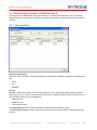
3.3.8 Project
IPETRONIK Engine Compartment Measurement
IPETRONIK GmbH & Co. KG
ipetronik.com
35/ 92
General software description
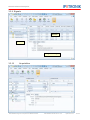
3.3.9 Signals
Channels
Systems
Configuration dialogs
3.3.10
Acquisition
IPETRONIK Engine Compartment Measurement
IPETRONIK GmbH & Co. KG
ipetronik.com
36/ 92
General software description
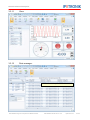
3.3.11
View
3.3.12
Data manager
Refer to IPEmotion hlep for further information
IPETRONIK Engine Compartment Measurement
IPETRONIK GmbH & Co. KG
ipetronik.com
37/ 92
General software description
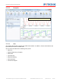
3.3.13
Analysis
Refer to IPEmotion hlep for further information
3.3.14
Info
The chapter offers a basic overview of the IPEmotion software. In addition, it shows useful advices and
tips and tricks on how to use IPEmotion.
The view Info is divided into the following menu points:
Welcome
Release Notes (only in English)
Red thread
Tips and tricks
Keyboard handling
Documentations
Contact and support
IPETRONIK Engine Compartment Measurement
IPETRONIK GmbH & Co. KG
ipetronik.com
38/ 92
General software description
3.3.15
The first acquisition
Step 1
Connect the device and switch it on
Connect the device(s) to a notebook/PC and to the power supply correctly poled, as described in chapter
Modular system structure. Cable types and lengths can vary depending on the application. Switch-on
the power supply. The devices will start measuring immediately after switching-on the power supply. The
status LED shows the current operating status (see chapter Interpretation of the LED display).
If you use M devices in one system together with SIM devices, please note the following advices:
Connect the cable for the power supply by using the SIM devices, not the M devices. The MCAN cables allow a lower current load than the SIM-CAN cables.
Only the M devices allow an operation at a DC supply voltage of 6 V to 42 (55) V. This range is
for almost all SIM devices 9 to 36 V.
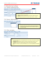
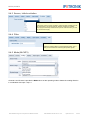
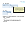
Step 2
Settings for the hardware interface
With the Signals main navigation tab under the CAN bus system
IPETRONIK-1 ► CAN hardware, you can configure the
communication with the measuring devices. Configuring the
settings is normally not required because IPEmotion
automatically detects the interface and the devices.
The baud rate of the CAN interface (Baud rate) can differ from the baud rate of the devices
(Device baud rate). When using e.g. devices with 1 MBd (MBit/s), which are currently set to
500 kBd (kBit/s), only change the baud rate of the devices to 1 MBd. The configuration data are
then sent with 500 kBd and the devices are finally set to 1 MBd. For automatically adapting the
CAN interface baud rate to the device baud rate, the Baud rate initialization must be
activated.
If there are devices in the system, which are set to different baud rates, they cannot be
addressed. For resetting all devices in a system to one (default) baud rate of 500 kBd, use the
M-DEF-100 or M-MOD-DEF-200 plugs.
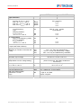
Step 3
Detecting devices, Reading out settings
IPEmotion automatically detects all available interfaces if they are activated with the Options ►
Frequently used function. The
corresponding PlugIn IPETRONIK
CAN must be activated (Options ►
PlugIns).
Select Detect or Automatic
generation for identifying all
connected hardware components. If
components are already existing in the
current system, these settings are
overwritten.
Save the current system configuration
if required.
IPETRONIK Engine Compartment Measurement
IPETRONIK GmbH & Co. KG
ipetronik.com
39/ 92
General software description
Detect
reads the connected devices and accepts the settings into the current
configuration.
Automatic generation
reads the connected devices, accepts the settings into the current
configuration, creates a storage group, and creates a graphic view.
Devices with default settings (no channel active) are transferred into the
storage group with a data rate of 1 Hz and all channels are activated.
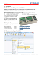
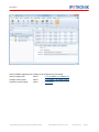
Step 4
Configuring the acquisition
CAN-Bus system
Select in the left window (Systems) the corresponding system for listing all channels/signals of the system
in the right window (Channels).
Select in the left window (Systems) the corresponding device for listing all channels/signals of the device
in the right window (Channels).
Channels
Systems
Configuration dialogs
Depending on having selected a system, a device or a channel, different tabs are available in the
configuration dialogs for further settings.
Settings of the scaling, as well as, the activating of channels can also be configured directly in the
channel table – all other settings can only be set with the configuration dialogs.
Every channel has configuration parameters, which do exist for all channel and device types (e.g.
General, Format, Display) and those, which do always differ because they are channel specific (e.g.
Sensor, Filter, Adjust).
The descriptions of the channel specific dialogs are shown in this manual with the respective devices.
IPETRONIK Engine Compartment Measurement
IPETRONIK GmbH & Co. KG
ipetronik.com
40/ 92
General software description
General
Active
Name
CAN system activated for using
Select any name for the system. The name can also be
automatically generated with the serial number.
Measuring system description
Description
Reference
CAN hardware
Medium
CAN interface , which connects the devices with the
PC/Notebook.
CAN bus
CAN interface bus for communicating (only if the
interface has several bus inputs)
Baud rate
Bus data rate of the CAN interface [kBit/s]
Device baud rate
Bus data rate of the devices [kBit/s]
Baud rate initialization IPEmotion initialized the CAN interface with the set
baud rate.
29-bit identifier
Use of 29-bit CAN identifier (Extended ID) for activating
the CAN messages.
Options
Synchronized mode
IPEmotion defines a device as clock generator, to which all
system devices are synchronized to.
Automatic CAN ID placing
IPEmotion automatically assigns the identifiers of the CAN
messages to a set rule.
Accelerated initialization
Only parameters, which have been changed, are reinitialized.
Names out of serial numbers Automatically generates the channel/signal name out of the
serial number of the respective device and the channel
number.
General settings and information about the device
General
Name
Description
Referenz
Sampling rate
IPETRONIK Engine Compartment Measurement
Select any name for the system. The name
can also be automatically generated with the
serial number.
Device description
CAN bus system for communicating with
IPEmotion
Signal acquiring rate for all channels (sampling
rate)
IPETRONIK GmbH & Co. KG
ipetronik.com
41/ 92
General software description
Select in the left window (Systems) the corresponding device for listing all channels/signals of the device
in the right window (Channels) and showing the tabs for the configuration dialogs.
Extended
Front number
Clock
Channel balance
The part of the serial number, which is imprinted on the device front. If the
devices are manually configured (without connected hardware), enter the front
number of the device for automatically creating the channel names (if Names
out of serial numbers is active).
Type od data detection
(Free = with internal hardware clock,
synchronized = common hardware clock for all system devices)
Offset calibration of the respective measuring chain of the device channels
Information
Calibration date
Hardware version
Firmware version
Date of the last device calibration
Hardware version of the device
Firmware version on the device
General configuration dialog
General
Active
Name
Kanal zur Verwendung aktiviert.
Select any name for the system. The name can also be
automatically generated with the serial number.
Channel or signal description
Serial number of the device
Description
Reference
Format
Data type
Resolution and sign of the digital value
(8 or 16 Bit, signed or unsigned)
Value, which is shown, if the current value is invalid
NoValue
Scaling
see Linear signal scaling
Mode
Selection of voltage and current acquisition, sets
the default unit V for voltage and A for current
Sensor signal range e.g. +/- 10 V, 0 ... 20 mA
Unit and range of the physical size e.g. 0 ... 5 bar
Sensor range
Physical range
Display
Min / Max
Decimal places
IPETRONIK Engine Compartment Measurement
Defines the y-axis range of the graphical
display for the Fix setting.
Defines the number of decimals of the
alphanumerical display, as well as, the current
value display in the signal tab
IPETRONIK GmbH & Co. KG
ipetronik.com
42/ 92
General software description
Step 5
Start displaying
Click Start displaying
within the main navigation tab Signals or View for starting the acquisition and
changing to the data displaying.
The connected devices are initialized with the current configuration. Finally, all values are shown in the
Current value column.
If you have already
created screen pages
for displaying the data
(e.g. y-t chart,
alphanumerical display,
analog pointer…), you
can select any screen
pages without
interrupting the running
acquisition.
Step 6
Start storing
Click Start storing
within the main navigation tab Acquisition or View for storing the data on a local
medium. First of all, a storage group is required, which contains at least one signal. If required, define
individual trigger conditions to start data storage.
IPETRONIK Engine Compartment Measurement
IPETRONIK GmbH & Co. KG
ipetronik.com
43/ 92
General software description
3.4 Downloading firmware (CANdownload 2)
The firmware of the IPETRONIK M devices is subject to continuous developments. You can use these
developments for your M devices. Therefore, an update of the devices’ processor software (Firmware) is
required.
3.4.1 User interface
Interface configuration
Define the used CAN driver, the corresponding port (if several are available), as well as, the desired baud
rate.
Driver
Port
Baudrate
Devices
Devices – Detect and update the connected devices, as well as, measuring chains and get information
about the device, the version, the default baud rate, and the available firmware. Please note that you can
only upgrade firmware and not downgrade it!
Detect devices
Update devices
Auto update devices
The Update devices function offers the ability to select the desired firmware version.
The Auto update devices function contains both functions and has no possibility to manually select the
firmware.
IPETRONIK Engine Compartment Measurement
IPETRONIK GmbH & Co. KG
ipetronik.com
44/ 92
General software description
Actions
Load the download file (*.cal) generated by IPETRONIK, which you received via e-mail from your
IPETRONIK support and download it to a specific device. In addition, define a specific device type and
the corresponding serial number. You can create and run an individual download process.
Load
Download
Please note that this process can only be run at connecting the device as a single device!
Entering the serial number is mandatory if the firmware contains a configuration file (Config.).
Library
Get an overview about the current CANdownload firmware versions and download the latest firmware
versions from a user defined directory into the CANdownload library.
Check for updates
To update a library, proceed as follows:
Select the desired IPETRONIK FTP connection string or a user defined directory.
Click on the Check for updates button. A progress bar shows the running updating process.
The current CANdownload 2 version supports the following structures for creating user defined
directories:
ftp://
file:///
file:////
CANdownload is based on the definition that only one directory for all update files and the fw.lst file is
required. You have the ability to use a user defined directory with own released firmware versions (see
chapter Creating an user defined library).
Please note the following need of using own libraries with firmware versions:
The file with the name fw.lst must be stored in the corresponding update folder. The file name
may not be changed!
IPETRONIK Engine Compartment Measurement
IPETRONIK GmbH & Co. KG
ipetronik.com
45/ 92
General software description
3.4.2 Creating a user defined library
CANdownload 2 allows for defining an own firmware library and creating an user defined directory with all
firmware files. If the access onto the corresponding directory is realized via the normal file access, the
storage of a text file in the user defined directory is mandatory! This file contains a list of the directory
content and is named fw.lst.
The library file name is structured as follows:
“device type”_”download type”_”version”.cdf
The current CANdownload 2 version supports the following download types:
DLK: Download kernel
RDLK: RAM Download kernel
ADLK: Application Download kernel
PIC: PIC-Firmware
FPGA: FPGA-Firmware
APPL: Firmware
TBL: Table
CFG: Config
SPC1: Input Processor 1
SPC2: Input Processor 2
SPC3: Input Processor 3
SPC4: Input Processor 4
FDLK: FPGA-Download kernel
PDLK: PIC-Download kernel
CDLK: Channel Processor Download kernel
CHN: Channel Prozessor Firmware
3.4.3 Manual configuration
To update the firmware of devices, proceed as follows:
Connect the devices with the power supply.
Click Detect devices. The appearing list contains the current firmware versions of each device. The
Target FW column shows a required update.
Select the latest firmware version.
Click Update devices to start the updating process. This process can take some minutes.
3.4.4 Automatic configuration
To automatically update the firmware of devices, proceed as follows:
Connect the devices with the power supply.
Click Auto update devices to start the updating process. All connected devices are automatically
detected and all firmware versions, which do not correspond to the latest one, are
updated. This
process can take some minutes.
IPETRONIK Engine Compartment Measurement
IPETRONIK GmbH & Co. KG
ipetronik.com
46/ 92
General software description
Please note
Due to continuous developments of the hardware and software components, incompatibilities
can occur. Please contact our support department at +49 (0) 7221/ 9922-333 or mail to
[email protected].
Make sure that the voltage supply will not be interrupted during the download process.
Do not run further programs under Windows during the download process.
If several devices in one system are updated, they must be set to one baud rate (see
“Configure HW…”). In case of doubt, the setting of the respective devices should be
checked because a break of the download process could cause a loss of being able to
address all devices.
After (every) successful firmware download, the device must be restarted (Power off/ Power on)
for guaranteeing a correct operating. This is especially required when transferring several files
to one device.
IPETRONIK Engine Compartment Measurement
IPETRONIK GmbH & Co. KG
ipetronik.com
47/ 92
General software description
3.5 Resetting devices to default values (M-MOD-DEF)
IPETRONIK offers the ability to simultaneously reset single or several devices to the respective default
values by using the default plugs (M-MOD-DEF-100, M-MOD-DEF-200). This is recommended if devices
are set to different and unknown baud rates for the data transfer. Or if a single device, which has not
been configured correctly, must be reset.
Preparation
Connect the devices and the M-MOD-DEF plug as shown above.
Switch-on the power supply.
How to proceed (M-MOD-DEF-100)
The proceeding is divided into three steps.
The default plug must be connected during booting.
Please note the chronology for a successful reinitialization.
IPETRONIK Engine Compartment Measurement
IPETRONIK GmbH & Co. KG
ipetronik.com
48/ 92
General software description
Brief instruction for proceeding:
Valid for firmware with release date > 12/2006
1. Connect M-MOD-DEF-100 plug
2. Switch-on voltage supply LED lights up
3. Wait 10 s, disconnect plug LED off
4. As soon as the LED relights, connect M-DEF again
5. As soon as the LED turns off, disconnect M-DEF again
6. Running initialization, LED lights up after approx. 5 s
7. Default initialization completed
If all steps were successful, the default initialization starts.
After the successful default initialization (approx. 5 s), the device(s) is in the standby mode because no
channels are active (LED is permanently on).
How to proceed (M-MOD-DEF-200)
Socket LED
1. Connect M-MOD-DEF-200 plug
2. Switch-on voltage supply
3. Device LED flashes, Plug LED flashes
4. Device LED is permanently on after a while, Plug LED flashes
5. The initialization is complete as soon as the plug LED turns off
6. Switch-off voltage supply and disconnect M-MOD-DEF-200
IPETRONIK Engine Compartment Measurement
IPETRONIK GmbH & Co. KG
ipetronik.com
49/ 92
M-THERMO2, M-THERMO 8, M-THERMO 16
4 M-THERMO2, M-THERMO 8, M-THERMO 16
4.1 Temperature acqusition with thermocouples
M-THERMO offers temperature acquisitions (range –60 °C to +1370 °C / -76 °F to 2498 °F) with thermocouples of K type as 8 channel, as well as, 16 channel version with miniature thermo sockets.
PT resistors at the aluminum tub of the sockets (M-THERMO 8/16) respective at each input connector
(M-THERMO2) calculate the thermo-electric voltage and provide the cold junction compensation. For
providing exact results within the entire acquisition range, the non-linear characteristic of the
thermocouple is adjusted by an internal linearization table. An optional impressed current through the
sensor allows a sensor break detection, which is activated within the software.
Due to the different thermo-electric voltages and the nonlinear characteristic, a thermocouple with an input of the
K type is not recommended for other thermocouples..
M-THERMO K16
M-THERMO K8
M-THERMO2 K8
4.2 Input cable 600-888.xxx
All input cables are also available in different lengths, as well as, with further plug
configurations.
IPETRONIK Engine Compartment Measurement
IPETRONIK GmbH & Co. KG
ipetronik.com
50/ 92
M-THERMO2, M-THERMO 8, M-THERMO 16
4.3 Specific input settings
The break detection and the averaging are activated within the configuration dialog Thermo.
4.3.1 Break detection
A low current flows through the thermocouple at activated sensor break detection, which has no
influence on the measuring result. If this flow is interrupted (sensor break), the result is –
Fullscale. A distinction between –Fullscale by sensor break and real –Fullscale value is not
possible. But the value –Fullscale is rarely possible. The break detection can therefore be used
for identifying errors.
4.3.2 Averaging
In order to reduce the noise level in a signal, M-THERMO offers the ability to activate the averaging. The
average value of the signals is calculated online over a period of the last 4 CAN sampling periods.
With a sampling rate of 10 Hz, the floating average is calculated online out of the 4 previous CAN outputs
and sent with the defined updating rate (here 10 Hz).
4.3.3 Status LED at the input
Only 16 channel thermocouples and the M-THERMO2 have a status LED at every input.
The respective LED indicates the following two states:
1. Identification of the respective channel during the
configuration. The LED flashes if the respective channel
or several channels are selected in the configuration
software.
2. Indication of a sensor break during measuring. The LED
is permanently on when interrupting the sensor current.
IPETRONIK Engine Compartment Measurement
IPETRONIK GmbH & Co. KG
ipetronik.com
51/ 92
M-THERMO2, M-THERMO 8, M-THERMO 16
4.4 Technical data (M-THERMO 8, M-THERMO 16)
M-THERMO 8
HW ≥ V 4.80, FW ≥ V 3.20
General
Voltage supply
Power consumption, typical
Operating temperature range
Permanent/ 1 hour
V DC
W
12, 24, 42, power supply, switch-off at voltage < 6 V
1.1
1.2
°C
-40 ... +120/ +120 ... +125
An immediate safety shutdown runs at T > 125 °C,
which is reset at T < 120 °C..
Notice
Storage temperature range
Relative humidity
Enclosure
Dimensions (W * H * D/D)
M-THERMO 16
°C
%
mm
-55 ... +150
5 ... 95
golden anodized aluminum, IP 67
120 * 41 * 55/58
204 * 41 * 55/58
Weight
Thermocouple input
g
320
Overvoltage protection
V
50
V
V
100, temporary (1 ms) 200
100, temporary (1 ms) 200
-60 to 1370
(without/with sockets)
Galvanic isolation
Input Device supply
Input Input
Range type K (Ni10Cr/NiAl)
Resolution
°C
°C
630
electrically isolated
0.174 ( 13 Bit)
look-up table, 13 Bit
Characteristic linearization
Cold junction compensation
Pt100
(Reference temperature over RTD)
Accuracy at 25 °C ambient temperature
and measured temperature of:
-60 °C ... 1000 °C / 1000 °C ... 1370 °C %
Drift at ambient temperature:
-40 °C ... +85 °C/+85 °C ... +120 °C
ppm/K
Input resistance, approx
MΩ
MΩ
Align of the AD converter
Sensor break detection
Status LED at the input
Hardware filter
Channel sample rates
Aggregate sample rate
CAN output
Hz
Hz
Hz
Programmable data rate
Data in the CAN message
Resolution / Format
Sign
Configuration interface
Bit/s
Bit
IPETRONIK Engine Compartment Measurement
2
4
±0.035 % / ±0.035 % + 3 K
20 / 30
1 (sensor break detection active)
10 (sensor break detection not active)
before acquiring a value
can be activated with the software
not available
1. Identification of the
respective channel
2. Sensor break displaying
in acquisition mode
1.0, filter type R-C-low pass 1st order
1/ 2/ 5/ 10/ 20
max. 160
max. 320
2.0 B, electrically isolated
max. 1 MBit/s acc. to ISO11898-2
8 / Byte or 16 / Word
signed, unsigned
CAN
IPETRONIK GmbH & Co. KG
ipetronik.com
52/ 92
M-THERMO2, M-THERMO 8, M-THERMO 16
4.5 Technical data (M-THERMO2)
General
Voltage supply
Power consumption, typical
Operating temperature range
Permanent/ 1 hour
V DC
W
°C
1.1
-40 ... +120/ +120 ... +125
An immediate safety shutdown runs at T > 125 °C,
which is reset at T < 120 °C..
Notice
Storage temperature range
Relative humidity
Enclosure
Dimensions (W * H * D)
Weight
Thermocouple input
6 to 36
°C
%
mm
g
-55 ... +150
5 ... 95
golden anodized aluminum, IP 67
106 * 30 * 50
250
electrically isolated
Galvanic isolation
Input Device supply
Input CAN
Input Input
V
V
V
nominal voltage 100 / pulse voltage 500
nominal voltage 100 / pulse voltage 500
nominal voltage 100 / pulse voltage 500
Range type K (Ni10Cr/NiAl)
Resolution
°C
°C
-60 to 1370
Characteristic linearization
Cold junction compensation
(Reference temperature over RTD)
Accuracy at 25 °C ambient temperature %
Drift at ambient temperature:
-40 °C ... +125 °C
ppm/K
Input resistance, approx
MΩ
MΩ
Align of the AD converter
Sensor break detection
Status LED at the input
Hardware filter
Channel sample rates
Aggregate sample rate
CAN output
Programmable data rate
Data in the CAN message
Resolution / Format
Sign
Configuration interface
Hz
1/min
Hz
Hz
Bit/s
Bit
IPETRONIK Engine Compartment Measurement
0.087 ( 14 Bit)
look-up table, 15 Bit
each input with Pt100
±0.035 % of total range
40
2.6 (sensor break detection active)
4.1 (sensor break detection not active)
before acquiring a value
can be activated with the software
1. Identification of the respective channel
2. Sensor break displaying in acquisition mode
1.0, filter type R-C-low pass 1st order
1/ 2/ 5/ 10
1/ 2/ 5/ 10/ 20/ 50/ 100
max. 800
2.0 B, electrically isolated
max. 1 MBit/s acc. to ISO11898-2
8 / Byte or 16 / Word
signed, unsigned
CAN
IPETRONIK GmbH & Co. KG
ipetronik.com
53/ 92
µ-THERMO
5 µ-THERMO
5.1 Temperature acqusition with thermocouples
µ-THERMO offers temperature acquisitions (range –60 °C to +1370 °C / -76 °F to 2498 °F) with
thermocouples of K type as 8 channel version with a 16-pin Lemo socket. 2 PT resistors in an isothermal
block calculate the thermo-electric voltage and provide the cold junction compensation. For providing
exact results within the entire acquisition range, the non-linear characteristic of the thermocouple is
adjusted by an internal linearization table. An optional impressed current through the sensor allows a
sensor break detection, which is activated within the software.
5.2 Input cable 625-506.xxx
IPETRONIK Engine Compartment Measurement
IPETRONIK GmbH & Co. KG
ipetronik.com
54/ 92
µ-THERMO
All input cables are also available in different lengths, as well as, with further plug
configurations.
5.3 Specific input settings
The break detection and the averaging are activated within the configuration dialog Thermo.
5.3.1 Break detection
A low current flows through the thermocouple at activated sensor break detection, which has no
influence on the measuring result. If this flow is interrupted (sensor break), the result is –
Fullscale. A distinction between –Fullscale by sensor break and real –Fullscale value is not
possible. But the value –Fullscale is rarely possible. The break detection can therefore be used
for identifying errors.
5.3.2 Averaging
In order to reduce the noise level in a signal, M-THERMO offers the ability to activate the averaging. The
average value of the signals is calculated online over a period of the last 4 CAN sampling periods.
With a sampling rate of 10 Hz, the floating average is calculated online out of the 4 previous CAN outputs
and sent with the defined updating rate (here 10 Hz).
Please also refer to Averaging at 4.3.2 M-THERMO
IPETRONIK Engine Compartment Measurement
IPETRONIK GmbH & Co. KG
ipetronik.com
55/ 92
µ-THERMO
5.4 Technical data
General
Voltage supply
Power consumption, typical
Operating temperature range
Permanent/ 1 hour
V DC
W
°C
Valid for HW version
≥ 5.20 and FW-Version ≥ 3.20
12, 24, 42, power supply, switch-off at voltage < 6 V
1.1
-40 ... +120/ +120 ... +125
An immediate safety shutdown runs at T > 125 °C,
which is reset at T < 120 °C..
Notice
Storage temperature range
Relative humidity
Enclosure
Dimensions (L * H * W)
Weight
Thermocouple input
°C
%
Overvoltage protection
V
50
Galvanic isolation
Input Device supply
Input Input
V
V
100, temporary (1 ms) 200
100, temporary (1 ms) 200
Range type K (Ni10Cr/NiAl)
Resolution
°C
°C
0.174 ( 13 Bit)
mm
g
Characteristic linearization
Cold junction compensation
2
(Reference temperature over RTD)
Accuracy at 25 °C ambient temperature
and measured temperature of:
-60 °C ... 1000 °C / 1000 °C ... 1370 °C %
Drift at ambient temperature:
-40 °C ... +85 °C/+85 °C ... +120 °C
ppm/K
Input resistance, approx
Align of the AD converter
Sensor break detection
Hardware filter
Channel sample rates
Aggregate sample rate
CAN output
Programmable data rate
Data in the CAN message
Resolution / Format
Sign
Configuration interface
MΩ
MΩ
Hz
Hz
Hz
Bit/s
Bit
IPETRONIK Engine Compartment Measurement
-55 ... +150
5 ... 95
golden anodized aluminum, IP 67
118 * 46 * 32
218
electrically isolated
-60 to 1370
look-up table, 13 Bit
Pt100
±0.035 % / ±0.035 % + 3 K
20 / 30
1 (sensor break detection active)
10 (sensor break detection not active)
before acquiring a value
can be activated with the software
1.0, filter type R-C-low pass 1st order
1/ 2/ 5/ 10/ 20
max. 160
2.0 B, electrically isolated
max. 1 MBit/s acc. to ISO11898-2
8 / Byte or 16 / Word
signed, unsigned
CAN
IPETRONIK GmbH & Co. KG
ipetronik.com
56/ 92
M-RTD2
6 M-RTD2
6.1 Temperature acqusition with RTDs (Pt100)
M-RTD2 offers temperature acquisitions (range –50 °C to +450 °C / -58 °F to 842 °F) with RTD sensors
(Pt100 resistor). The 4-wire sensor connection ensures good accuracy even for long distance sensor
cables.
6.2 Input cable 670-937.xxx
All input cables are also available in different lengths, as well as, with further plug
configurations.
IPETRONIK Engine Compartment Measurement
IPETRONIK GmbH & Co. KG
ipetronik.com
57/ 92
M-RTD2
6.3 Specific input settings
6.3.1 Scaling
The settings for the sensor range are fixed for Pt100 RTDs. Physical range default settings are equal to
the sensor range. The user can modify the physical range for individual scaling.
6.3.2 Averaging
Enter the Thermo tab to activate the moving average function.
The sensor break detection is always activated.
The monitoring of the constant current through the RTD is used to detect a sensor break.
A distinction between –Fullscale by sensor break and real –Fullscale value is supported.
IPETRONIK Engine Compartment Measurement
IPETRONIK GmbH & Co. KG
ipetronik.com
58/ 92
M-RTD2
6.4 Technical data
General
Voltage supply
Power consumption, typical
Operating temperature range
Permanent/ 1 hour
V DC
W
°C
Galvanic isolation
Input Device supply
Input Excitation
Input CAN
Input Input
Range Pt100
AD converter resolution (ADC SAR)
Accuracy at ambient temperature
Ta = 25 °C
Ta = -40 °C to 85 °C
Ta = -40 °C to 125 °C
Hardware filter
Channel sample rates
Aggregate sample rate
CAN output
Programmable data rate
Data in the CAN message
Resolution / Format
Sign
Configuration interface
-40 ... +120/ +120 ... +125
An immediate safety shutdown runs at T > 125 °C,
which is reset at T < 120 °C..
Notice
Storage temperature range
Relative humidity
Enclosure
Dimensions (W * H * D)
Weight
RTD input
9 to 36, switch-off at voltage < 6 V
2.5
°C
%
mm
g
V
V
V
V
°C
Bit
-40 ... +150
5 ... 95
golden anodized aluminum, IP 67
106 * 43 * 60
400
electrically isolated
100, temporary (1 ms) 200
100, temporary (1 ms) 200
100, temporary (1 ms) 200
100, temporary (1 ms) 200
-50 to 450
16
K
K
K
Hz
1/min
Hz
Hz
±0.10 K
(0.02 % of total range)
±0.60 K
(0.12 % of total range)
±1.25 K
(0.25 % of total range)
150 Hz, filter typ Butterworth 8-pole
1/ 2/ 5/ 10
1/ 2/ 5/ 10/ 20 / 50/ 100
max. 400
2.0 B, electrically isolated
Bit/s
max. 1 MBit/s acc. to ISO11898-2
Bit
IPETRONIK Engine Compartment Measurement
8 / Byte or 16 / Word
signed, unsigned
CAN
IPETRONIK GmbH & Co. KG
ipetronik.com
59/ 92
M-SENS, M-SENS2, M-SENS 8/8plus
7 M-SENS, M-SENS2, M-SENS 8/8plus
7.1 Voltage/Current acquisition with sensor excitation
The M-SENS is an universal measuring device for acquiring voltages, currents, and sensor signals of
active sensors. It provides 4 or 8 analog inputs and allows the setting of different voltage and current
acquisition ranges, as well as, different channel sampling rates.
The channels and the separately adjustable sensor supply voltages are electrically isolated to each other,
to the other channels, to the supply voltage, and to the CAN bus.
M-SENS 8
M-SENS
M-SENS 8plus
M-SENS2
The sockets for the inputs are available in Lemo. Other sockets and ODU versions (Fips)
on request.
IPETRONIK Engine Compartment Measurement
IPETRONIK GmbH & Co. KG
ipetronik.com
60/ 92
M-SENS, M-SENS2, M-SENS 8/8plus
7.2 Input cable 670-xxx.xxx
7.2.1 Input cable 670-807.xxx (M-SENS 4, SIM-SENS)
Only M-SENS 8 and M-SENS 8plus provide a negative sensor supply via pin 6. M-SENS
reserves this pin for TEDS.
7.2.2 Input cable 670-810.xxx (M-SENS 8 / 8plus)
IPETRONIK Engine Compartment Measurement
IPETRONIK GmbH & Co. KG
ipetronik.com
61/ 92
M-SENS, M-SENS2, M-SENS 8/8plus
All input cables are also available in different lengths, as well as, with further plug
configurations.
7.3 Input / Principle details
7.3.1 Filter in the measurement engineering - Why do we use filters?
Filters of analog measuring amplifiers are used for avoiding interrupting frequencies (frequency
spectra, which do not contribute to the signal and/or which cannot be processed by the
system). A low pass filter, which reduces the amplitudes of the frequencies above a specific
cut-off frequency, is usually used for avoiding negative effects to the useful signal. The
threshold in the range of the cut-off frequency (the barrier between the useful and the
unrequested signal) is continuous.
Depending on the measuring task, the following filter properties are to be respected:
Useful signals below the cut-off frequency are also damped. (A damping of 3 dB at the cut-off
frequency means a reduction of the initial signal of 30 %.)
Filters always cause a time shifting (phase shifting) between the initial signal and the filtered one. The
value of the phase shifting depends on the filter type (e.g. Bessel, Butterworth, Tschebyscheff) and the
filter order (pole number).
The image above shows the result of two inputs with the same input signal of 4 V amplitude and 12.5 Hz
frequency.
Channel 2
Channel 3
black
red
without filter
with 30 Hz hardware filter (Bessel type)
Channel 3 clearly shows the damping, the phase shifting, as well as, the start oscillation of the filter.
IPETRONIK Engine Compartment Measurement
IPETRONIK GmbH & Co. KG
ipetronik.com
62/ 92
M-SENS, M-SENS2, M-SENS 8/8plus
7.3.2 Filter in the measurement engineering - How do we use filters?
Modern systems offer qualified hardware filters and, if applicable, additional software filters
(Digital Signal Processor DSP).
Although today’s microprocessors provide a high processing power, the use of hardware filters is still
essential. Especially when users cannot exclude that (periodic) signals can pass the AD converter and
software filter, which cannot process the signals. Every sampling system follows Shannon’s sampling
theorem whereby one must at least sample with twice the signal frequency. Otherwise, aliasing effects
can occur, whereas the acquired frequency is considerably lower than the actual signal (see image
below).
But this theoretic view is not sufficient for practical applications because the systems (compared to lab
devices) do not have FFT analyzers (Fast Fourier Transformation) for calculating the initial frequency.
The hardware filter frequency of IPETRONIK devices with voltage inputs (VIN, SENS) is approx. 1/10 of
the maximum sampling rate e.g. 100 Hz at 1 kHz max. sampling rate.
Why do we additionally filter with DSP?
The hardware filter at the input excludes a distortion by frequency spectra above the system limit with the
maximum sampling rate. Depending on the application, it can be required to lower the cut-off frequency.
Example:
M-SENS devices provide a switchable hardware filter with 150 Hz cut-off frequency. If the cut-off
frequency is e.g. 50 Hz, interrupting frequency spectra (of devices with additional software filter) in the
range between 50 Hz and the hardware filter frequency can be filtered with DSP. The filter frequency can
be configured in defined steps up to the hardware filter frequency.
Aliasing effects in spite of hardware and software filter?
Despite sophisticated measurement engineering, errors can occur due to wrong settings. If, for
example, a 100 Hz signal is acquired with a sampling rate of 100 Hz (also the output rate to the
CAN bus). The system can independently acquire the correct signal, but the result is wrong
because the sampling rate was set too low. This is especially valid for devices with DSP. The
DSP always acquires the signal with a higher clock rate than the maximum adjustable sampling
rate. If the signal is sent to the CAN bus with a lower sampling / output rate, the result does not
reflect the initial signal.
IPETRONIK Engine Compartment Measurement
IPETRONIK GmbH & Co. KG
ipetronik.com
63/ 92
M-SENS, M-SENS2, M-SENS 8/8plus
7.4 Extended input settings
7.4.1 Scaling, measuring range
Scaling
1.
2.
3.
Select the voltage or current acquisition.
Select a sensor range. Depending on the device/channel, different ranges are
available.
Define a physical range and the unit with the scaling calculator – if required.
7.4.2 Sensor, initial excitation
Sensor
-
If the sensor rquires a sensor excitation, select the initial excitation from the
list. Depending on the device/channel, different voltages are available.
The supply is electrically isolated to the input and channels nearby, as well
as, to the device supply.
7.4.3 Filter, averaging
Filter
1.
2.
3.
Activate the hardware filter for avoiding aliasing effects. This is always recommended for measuring
with periodic signals.
Activate the averaging (floating average) for smoothing unrequested signal interrupts or noise
components.
Activate the software filter for additionally filtering the signal. Select the filter type (Bessel,
Butterworth, Tschebychev ) and the cut-off frequency (0.1 Hz...495.0 Hz, depending on the sampling
rate).
IPETRONIK Engine Compartment Measurement
IPETRONIK GmbH & Co. KG
ipetronik.com
64/ 92
M-SENS, M-SENS2, M-SENS 8/8plus
7.4.4 Offset adjust
The offset adjustment is supported by the respective device from the following firmware version:
M-SENS, M-SENS 8 >=
V3.12.07
M-SENS 8plus
>=
V3.12.08
The calibration function with a broadcast command (IPEhotkey) also allows the offset adjustment during a
running acquisition to a user defined target value (reference value). The following actions are permitted:
None
no offset calibration
Manually only channels with this status are calibrated with the Manual calibration
command
Group X channels, which are assigned to a specific group (1…4), are calibrated
with the desktop icon IPEhotkey and the Calibration Group command.
The channel assignation to one group can also be effected for all devices (e.g.
SENS type, STG, CANpressure mixed in one group). A signal-based calibration
is therefore possible.
7.4.5 Status-LED am Messeingang
Only M-SENS 8 and M-SENS 8plus devices have a status LED at every input. The respective LED
indicates the following two states:
1. Identification of the respective channel during the
configuration. The LED flashes if the respective channel or
several channels are selected in the configuration software.
2. Indication of an overcurrent during measuring. The LED is
permanently on if the maximum current load of the respective
sensor excitation is exceeded.
IPETRONIK Engine Compartment Measurement
IPETRONIK GmbH & Co. KG
ipetronik.com
65/ 92
M-SENS, M-SENS2, M-SENS 8/8plus
7.5 Technical data
7.5.1 M-SENS, M-SENS2
M-SENS
HW ≥ V 3.20
General
Voltage supply
Power consumption, typical / maximum
Operating temperature range
Permanent/ 1 hour
V DC
W
°C
9 to 36, switch-off at voltage < 6 V
3.0 / 9.0
3.0 / 9.0
-40 ... +120/ +120 ... +125
An immediate safety shutdown runs at T > 125 °C,
which is reset at T < 120 °C..
Notice
Storage temperature range
Relative humidity
Enclosure
Dimensions (W * H * D)
Weight
Voltage / current input
M-SENS2
°C
%
mm
g
-55 ... +150
5 ... 95
golden anodized aluminum, IP 67
120 * 41 * 55
106 * 43 * 58
370
380
electrically isolated
Galvanic isolation
Input Device supply
Input Excitation
Excitation Device supply
Input Input
V
V
V
V
100, t = 1 ms: 200
100, t = 1 ms: 200
100, t = 1 ms: 200
100, t = 1 ms: 200
100 Unominal, 500 Upulse
100 Unominal, 500 Upulse
100 Unominal, 500 Upulse
100 Unominal, 500 Upulse
Acquisition ranges
Voltage unipolar (0 ... )
V
Input resistance
Voltage bipolar (+/-)
MΩ
V
Input resistance
Current (unipolar, bipolar)
Input resistance
MΩ
mA
Ω
0.1/ 0.2/ 0.5/ 1/ 2/ 5/
10/ 20/ 30/ 50/ 60/ 100
10
0.1/ 0.2/ 0.5/ 1/ 2/ 5/
10/ 20/ 30/ 50/ 60/ 100
10
0.1/ 0.2/ 0.5/ 1/ 2/ 5/
10/ 20/ 30/ 50/ 60/ 100
10
0.1/ 0.2/ 0.5/ 1/ 2/ 5/
10/ 20/ 30/ 50/ 60/ 100
10
Resolution
Accuracy at TAmbient = 25 °C
Voltagesn bipolar
Voltages unipolar
Currents bipolar / unipolar
Drift at TAmbient
-40 °C to +85 °C
+85 °C to +105 °C
+105 °C to +125 °C
Bit
0 ... 20, 20
50
16
%
%
%
0.05
0.13
0.30
0.30
0.30
0.30
ppm/K
ppm/K
ppm/K
40
80
120
40
80
120
IPETRONIK Engine Compartment Measurement
IPETRONIK GmbH & Co. KG
ipetronik.com
66/ 92
M-SENS, M-SENS2, M-SENS 8/8plus
M-SENS
M-SENS2
Filter, sample rates
Hardware filter
Frequency
Type
Channel sample rates
Aggregate sample rate
Sensor excitation
Hz
Hz
kHz
Selectable output voltage
V
Output current
Short-circuit protection
Accuracy at TAmbient
and voltage output 10 V
+23 °C
+85 °C
+120 °C
mA
off/
off/
2.5/ 5.0/ 7.5/
2,5/ 5.0/ 7.5/
10.0/ 12.5/ 15.0
10.0/ 12.5/ 15.0
max. 60
max. 60
Current limiting with safety shutdown at overcurrent
%
%
%
0.20
0.20
0.40
0.40
0.60
0.60
2.0 B, electrically isolated
Bit/s
max. 1 MBit/s acc. to ISO11898-2
CAN output
Programmable data rate
Data in the CAN message
Resolution / Format
Sign
Configuration interface
150
500
8-pole Butterworth
8-pole Butterworth
1/ 2/ 5/ 10/ 20/ 50/ 100/ 200/ 500/ 1000/ 2000
max. 8
max. 8
single, galvan. isolated single, galvan. isolated
Bit
IPETRONIK Engine Compartment Measurement
8 / Byte or 16 / Word
signed, unsigned
CAN
IPETRONIK GmbH & Co. KG
ipetronik.com
67/ 92
M-SENS, M-SENS2, M-SENS 8/8plus
7.5.2 M-SENS 8, M-SENS 8plus
M-SENS 8
M-SENS 8plus
General
Voltage supply
Power consumption, typical / maximum
Operating temperature range
Permanent/ 1 hour
V DC
W
°C
Galvanic isolation
Input Device supply
Input Excitation
Input CAN
Input Input
Acquisition ranges
Voltage unipolar (0 ... )
-40 ... +120/ +120 ... +125
An immediate safety shutdown runs at T > 125 °C,
which is reset at T < 120 °C..
Notice
Storage temperature range
Relative humidity
Enclosure
Dimensions (W * H * D)
Weight
Voltage / current input
9 to 36, switch-off at voltage < 6 V
3.5 / 11.0
3.5 / 11.0
°C
%
mm
g
V
V
V
V
V
Input resistance
Voltage bipolar (+/-)
MΩ
V
Input resistance
Current (unipolar, bipolar)
Input resistance
MΩ
mA
Ω
Resolution
Accuracy at TAmbient = 25 °C
Voltagesn bipolar
Voltages unipolar
Currents bipolar / unipolar
Drift at TAmbient
-40 °C to +85 °C
+85 °C to +105 °C
+105 °C to +125 °C (range ≥ 0.1 V)
+105 °C to +125 °C (range 0.01 V)
Bit
-55 ... +150
5 ... 95
golden anodized aluminum, IP 67
204 * 41 * 55
204 * 41 * 55
695
695
electrically isolated
100, temporary (1 ms) 200
100, temporary (1 ms) 200
100, temporary (1 ms) 200
100, temporary (1 ms) 200
0.1/ 0.2/ 0.5/ 1/ 2/ 5/
10/ 20/ 30/ 50/ 100
10
0.1/ 0.2/ 0.5/ 1/ 2/ 5/
10/ 20/ 30/ 50/ 100
10
0 ... 20, 20
50
16
%
%
%
0.10
0.15
0.50
ppm/K
ppm/K
ppm/K
ppm/K
40
80
250
Status LED at the input
IPETRONIK Engine Compartment Measurement
0.01/ 0.1/ 0.2/ 0.5/ 1/ 2/ 5/
10/ 20/ 30/ 50/ 100
10
0.01/ 0.1/ 0.2/ 0.5/ 1/ 2/ 5/
10/ 20/ 30/ 50/ 100
10
0.06
0.10
0.40
40
80
250
450
1. Identification of the respective channel
2. Overcurrent displaying in acqusition mode
IPETRONIK GmbH & Co. KG
ipetronik.com
68/ 92
M-SENS, M-SENS2, M-SENS 8/8plus
M-SENS 8
M-SENS 8plus
Filter, sample rates
Hardware filter
Frequency
Type
Channel sample rates
Aggregate sample rate
Hz
Hz
kHz
150
8-pole Butterworth
1/ 2/ 5/ 10/ 20/ 50/ 100/ 200/ 500/ 1000/ 2000
max. 16
(at 1 MBit/s data rate without additional bus load of further devices)
Sensor excitation
dual, electrically isolated
Selectable output voltage
V
off/
2.5/ 5.0/ 7.5/ 8.0/ 10.0/12.5/ 15.0
Output current
mA
25
mA
mA
mA
max. 30
max. 30
max. 40
max. 40
max. 45
max. 45
25
(independent from the output voltage setting)
Initial current at an output voltage of
2.5 or 10.0 V
5.0 or 12.5 V
7.5 or 15.0 V
Derating
%/K
Short-circuit protection
Accuracy at TAmbient
and voltage output 10 V
-40 °C
+23 °C
+85 °C
+120 °C
Current limiting with safety shutdown at overcurrent
%
%
%
%
0.50
0.40
0.30
0.25
0.50
0.40
0.70
0.50
2.0 B, electrically isolated
Bit/s
max. 1 MBit/s acc. to ISO11898-2
CAN output
Programmable data rate
Data in the CAN message
Resolution / Format
Sign
Configuration interface
-1,25
(from 85 °C ambient temperature)
The sum of the maximum output power of the
sensor supplies is reduced with the increasing
ambient temperature by this percentage per Kelvin!
Bit
IPETRONIK Engine Compartment Measurement
8 / Byte or 16 / Word
signed, unsigned
CAN
IPETRONIK GmbH & Co. KG
ipetronik.com
69/ 92
Mc-THERMO
8 Mc-THERMO
8.1 Voltage and temperature acquisition
Mc-THERMO is an universal measuring device for acquiring temperatures from –60 °C to +1370 °C /
-76 °F to +2498 °F with thermocouples of the K type and voltages up to 30 V. Each of the 8 analog
inputs can be configured with the configuration and measuring software IPEmotion.
The channels are electrically isolated to each other, to the other channels, to the supply voltage, and to
the CAN bus.
8.2 Input cable
Different input cables are available for acquiring the temperature and voltage signals. The thermocouple
input cables are listed under the M-THERMO.
The following cables are used for the voltage measuring with Mc-THERMO. All Mc-THERMO
VIN CL cables provide a current limiter for avoiding the danger of a short circuit due to the open
ends of the connected thermo plug.
8.2.1 Input cable 620-644.xxx Mc-THERMO VIN CL Cable open
IPETRONIK Engine Compartment Measurement
IPETRONIK GmbH & Co. KG
ipetronik.com
70/ 92
Mc-THERMO
8.2.2 Input cable 620-645.xxx Mc-THERMO VIN CL Cable Banana
8.2.3 Input cable 620-643.xxx Mc-THERMO VIN CL Cable BNC/S
IPETRONIK Engine Compartment Measurement
IPETRONIK GmbH & Co. KG
ipetronik.com
71/ 92
Mc-THERMO
8.3 Extended input settings
8.3.1 Sensor mode
Scaling
Select the sensor mode for voltage or temperature acqusition.
Thermocouple
Voltage
Temperature with thermocouple K type,
Range –60 °C ... +1370 °C
Voltage
Range –30 V ... +30 V
8.3.2 Break detection and averaging
Thermo
Break detection
Averaging
Activates the sensor break detection
Activates the floating averaging out of
previous averages
8.4 Technical data
General
Voltage supply
VDC
6 to 36
W
1.1
°C
-40 ... +125 (Continuous operation)
Power input, typical
Working temperature range
An immediate safety shutdown runs at T > 125 °C,
which is reset at T < 120 °C.
Storage temperature range
°C
-55 ... +150
Relative humidity
%
5 ... 95
Input sockets
Front membrane color acc. to DIN IEC 584
Front membrane color acc. to ANSI MC 96.1
Miniature thermocouple sockets
green
yellow
Enclosure
Aluminium, nature anodized, IP 65
Dimensions (W*H*D)
mm
106 * 24* 50
Weight
g
215
Temperature / Voltage input
electrically isolated
Input voltage max.
V
50 (permanent), 100 (t < 2ms)
Galvanic separation
Input Device supply
Input CAN
all inputs
V
V
V
50, temporary (2 ms) 200
50, temporary (2 ms) 200
50, temporary (2 ms) 200
IPETRONIK Engine Compartment Measurement
IPETRONIK GmbH & Co. KG
ipetronik.com
72/ 92
Mc-THERMO
Temperature measuring range
°C
-60 to 1370
Sensor type
Thermocouple K type (Ni10Cr/NiAl)
Resolution
0.087 ( 14 Bit) at 1 Hz sampling rate
°C
Characteristic linearization
numeric, interpolated, resolution 15 bit
Cold junction compensation
PT100 for reference temperature
measurement at every input
Accuracy [1] at 25 °C ambient temperature
%/K
±0.035 % of the temperature acqu. range
at 1 Hz sampling rate
Drift [1] at ambient temperature:
-40 °C to +85 °C
+85 °C to +125 °C
ppm/K
ppm/K
±40
±40
Input resistance, approx.
MΩ
MΩ
2.6
4.1
Hardware filter
Hz
10, R-C low pass filter type 1st order
Sensor break detection
(Sensor break detection active)
(Sensor break detection deactivated)
can be activated with the software
30
Voltage measuring range
V
Resolution
mV / Bit 0,92 (16 Bit)
[1]
%/V
±0.1 % of the voltage acqu. range
(±60 mV) at 1 Hz sampling rate
ppm/K
ppm/K
±50
±50
Input resistance, approx.
MΩ
MΩ
MΩ
4.1 @ TA = 25 °C
3.6 @ TA = 85 °C
1.2 @ TA = 125 °C
Hardware filter
Hz
330, R-C low pass filter type 1st order
Bit
24
Accuracy
at 25 °C ambient temperature
Drift [1] at ambient temperature:
-40 °C to +85 °C
+85 °C to +125 °C
General input
Resolution ADC
Calibration of the A/D chain
before acquiring a value
Status LED at the input
1. Identification of the respective channel
during the configuration (LED flashes)
2. Sensor break displaying in acqu. mode
(LED is permanently on)
Channel sampling rates
Hz
0.033/ 0.083/ 0.167/ 1/ 2/ 5/ 10/ 20/ 50/ 100
Aggregate sample rate
Hz
max. 800
CAN output
Programmable data rate
Data in the CAN message
Resolution / Format
Sign
Configuration interface
IPETRONIK Engine Compartment Measurement
2.0 B, electrically isolated
Bit/s
max. 1 MBit/s acc. to ISO11898-2
Bit
8 / Byte or 16 / Word
signed, unsigned
CAN
IPETRONIK GmbH & Co. KG
ipetronik.com
73/ 92
M-FRQ, M-CNT2
9 M-FRQ, M-CNT2
9.1 Frequecy- / Cycle acquisition incl. sensor supply
The M-FRQ and M-CNT2 are universal counters. Main applications are the acquisition of inductive
sensors in the fields ABS, wheel speed and fan speed. The following measuring modes are available:
frequency, cycle, pulse, pause duration and duty cycle. The device provides 4 signal inputs with
adjustable trigger thresholds, 2 voltage ranges for data evaluation and different channel sampling rates.
The channels and the separately adjustable sensor supply
per channel are electrically isolated to each other, to the
other channels, to the supply voltage, and to the CAN bus.
M-FRQ
M-CNT2
The sockets for the inputs are available in Lemo. Other sockets and ODU versions (Fips)
on request.
IPETRONIK Engine Compartment Measurement
IPETRONIK GmbH & Co. KG
ipetronik.com
74/ 92
M-FRQ, M-CNT2
9.2 Input cable 670-858.xxx
All input cables are also available in different lengths, as well as, with further plug
configurations.
IPETRONIK Engine Compartment Measurement
IPETRONIK GmbH & Co. KG
ipetronik.com
75/ 92
M-FRQ, M-CNT2
9.3 Input / Principle details
9.3.1 Measuring method
The analog and digital input signal is evaluated with a programmable comparator threshold (switching
threshold, hysteresis) and the following 48 bit counter. The FPGA and the digital signal processor (DSP)
convert the respective counter values online into a frequency output (and duty cycle or time period).
The input signal is compared with the defined switching thresholds by using a comparator (see image).
The result is a square wave voltage similar to the frequency at the comparator output. The pulse and the
interval duration of this square wave voltage is detected with the internal 100 MHz counter.
If the timeout expires without any detection of an ON threshold, the zero indication will output the user
defined minimal value. The setting of the timeout is recommended in order to avoid time delays in signal
evaluation. A correct signal evaluation is supported only with sequent detections of ON and OFF
thresholds.
Frequency
The frequency is acquired with the interval duration acquisition described above. The reciprocal value of
the counter result of the interval duration measurement is scaled and sent correspondingly to the
measuring range setting.
Duty cycle
The counter value of the pulse duration is divided by the counter value of the interval duration and
correspondingly scaled and sent to the measuring range setting.
If the frequency is too low (or 0 Hz), 0 % (low level) or 100 % (high level) is sent depending on the signal
level.
The thresholds on and off do usually differ and cause different results of the pulse duration and the duty
cycle if the signal edges are low, depending on the defined thresholds.
IPETRONIK Engine Compartment Measurement
IPETRONIK GmbH & Co. KG
ipetronik.com
76/ 92
M-FRQ, M-CNT2
Interval duration
The interval duration is acquired with the acquisition described above. The counter value between two
thresholds on is detected, scaled, and sent correspondingly to the measuring range setting.
Pulse duration
The pulse duration is acquired with the acquisition described above. The counter value between the
threshold on and the threshold off is detected, scaled, and sent correspondingly to the measuring range
setting.
The thresholds on and off do usually differ and cause different results of the pulse duration if the signal
edges are low, depending on the defined thresholds.
Pause duration
The pause duration acquisition corresponds to the pulse duration acquisition with inverted input signal.
9.3.2 Status LED at the input
The status LED at the respective input indicates the acquisition of a frequency signal. This is the case if
both switching thresholds of every value are reached (threshold on and off).
The status LED is on / flashes in time with the signal frequency if:
the corresponding channel is active and
the device is in the acquisition mode (acquiring data) and
the switching thresholds are correctly defined.
Due to the slowness of visual proceeding, only frequencies under approx. 10 Hz can be seen as a
flashing. The LED is permanently on at higher signal frequencies.
9.4 Extended input settings
9.4.1 Scaling, measuring ranges
Scaling M-FRQ
Scaling M-CNT2
Scaling
1.
2.
3.
Select the mode for frequency or period acquisition.
Select a sensor range. Depending on the device/channel,
different ranges are available.
Define a physical range and the unit with the scaling
calculator – if required.
IPETRONIK Engine Compartment Measurement
IPETRONIK GmbH & Co. KG
ipetronik.com
77/ 92
M-FRQ, M-CNT2
Mode
Remarks
Ranges
Min.
Max.
Unit
Frequency
0 ... 200
0 ... 200
kHz
Maximum > Minimum
minimum signal frequency 0.03 Hz
maximum signal frequency 200 kHz
Duty cycle
Range
0.01 % to 99.99 %
0 ... 100
0 ... 100
%
Periodic duration
0 ... 200
0 ... 200
s
Pulse duration
0 ... 200
0 ... 200
s
Pause duration
0 ... 200
0 ... 200
s
Maximum > Minimum
minimum signal frequency 0.03 Hz
maximum signal frequency:
10 kHz at 1 % duty cycle
250 kHz at 25 % duty cycle
500 kHz at 50 % duty cycle
250 kHz at 75 % duty cycle
10 kHz at 99 % duty cycle
Maximum > Minimum
maximum interval duration 200 s
minimum interval duration 1 µs
Maximum > Minimum
maximum pulse duration 200 s
minimum pulse duration 1 µs
Maximum > Minimum
maximum pause duration 200 s
minimum pause duration 1 µs
Select values >=1 Hz for the frequency with Sensor range Min! This avoids an unnecessary
long response time until the value 0 Hz or –FS is sent if a signal is missing or has the value
approx. 0 Hz. The maximum response time at 0 Hz is 40 s.
9.4.2 Input signal
Input signal
1.
2.
3.
4.
Select the upper threshold with Threshold on in a range of +/-40 V.
Select the lower threshold with Threshold off in a range of +/-40 V.
The lower threshold must always smaller than the upper one.
Select an edge for defining the positive or negative signal edge. If
the negative edge is selected, the input signal will be inverted.
The DC compensation disables the direct current component in the
signal with a passive high-pass (1-pole, 0.8 Hz cut-off frequency).
An oscilloscope is recommended for displaying the signal behavior for configuring the switching
thresholds on and off. If the sensor signal does not exceed the threshold on or fall below the threshold off,
no exact acquisition is possible. In this case, the value does not change although the revolutions per
minute increase and the sensor is connected correctly. Correct the threshold values in the configuration
and run a test acquisition.
Please note that a lot of speed sensors send an almost ideal square wave signal in the lower
frequency range, but the graph changes with increasing frequency (> saw tooth). This can also
be caused by external capacities e.g. a (long) connection cable to the sensor.
IPETRONIK Engine Compartment Measurement
IPETRONIK GmbH & Co. KG
ipetronik.com
78/ 92
M-FRQ, M-CNT2
9.4.3 Sensor, initial excitation
Sensor
If the sensor rquires a sensor excitation, select the initial excitation from the
list. Depending on the device/channel, different voltages are available.
The supply is electrically isolated to the input and channels nearby, as well
as, to the device supply.
9.4.4 Filter
Filter
Select the hardware filter for avoiding aliasing effects. This is
always recommended for measuring with periodic signals.
9.4.5 Mode (M-CNT2)
Channel 2 and Channel 4 provide the Mode tab to set the operating mode to detect the rotating direction
in combination with input 1 resp. 3.
IPETRONIK Engine Compartment Measurement
IPETRONIK GmbH & Co. KG
ipetronik.com
79/ 92
M-FRQ, M-CNT2
9.5 Technical data
M-FRQ
M-CNT2
General
Voltage supply
Power input, typical / maximum
Working temperature range
V DC
W
°C
9 to 36, switch-off at voltage < 6 V
2.0 / 7.0
2.0 / 7.0
-40 ... +120/ +120 ... +125
An immediate safety shutdown runs at T > 125 °C, which is reset
at T < 120 °C.
Storage temperature range
Relative humidity
Enclosure
Dimensions (W * H * D)
Weight
°C
%
mm
g
Voltage input
electrically isolated
Galvanic isolation
Input Device supply
Input Excitation
Excitation Device supply
Input Input
Adjustable thresholds
Range 1 / (Quantization)
Range 2 / (Quantization)
Accuracy at TAmbient = 25 °C
Accuracy at -40 < TAmbient < 120 °C
V
V
V
V
V
V
%
%
Signal evaluation
Frequency mode
min. signal frequency
max. signal frequency
Duty cycle mode
min. signal frequency
max. signal frequency
Resolution
Period, pulse, pause duration mode
min.
max.
Resolution
-55 ... +150
5 ... 95
golden anodized aluminum, IP 67
120 * 41 * 55
106 * 43 * 58
350
370
100, t = 1 ms: 200
100 Unominal, 500 Upulse
100 Unominal, 500 Upulse
100, t = 1 ms: 200
100 Unominal, 500 Upulse
100, t = 1 ms: 200
100 Unominal, 500 Upulse
100, t = 1 ms: 200
Evalutation with voltage comparator
4 / (0.025)
40 / (0.2)
3
8
Online with DSP
Hz
kHz
%
Hz
kHz
µs
µs
s
µs
Event counting mode
IPETRONIK Engine Compartment Measurement
0.03
200
Measuring range 0.01 % to 99.99 %
0.03
10
at
1 % Duty cycle
250
at
25 % Duty cycle
500
at
50 % Duty cycle
250
at
75 % Duty cycle
10
at
99 % Duty cycle
1 or 1/100 fg Filter (greater value)
1
200
1 or 1/100 fg Filter (greater value)
Reset functions: without
reset, reset at clock,
overflow,
Up / down counting with
detection of rotation
direction
IPETRONIK GmbH & Co. KG
ipetronik.com
80/ 92
M-FRQ, M-CNT2
M-FRQ
M-CNT2
Signal evaluation
Internal time basis
Accuracy at TAmbient = 25 °C
Drift, -40 < TAmbient < 85 °C
Drift, 85 < TAmbientg < 105 °C
Drift, 105 < TAmbient < 125 °C
Hardwarefilter
Cut-off frequency
Type
Damping deviation
TAmbient = 25 °C
-40 < TAmbient < 120 °C
DC compensation
lower cut-off frequency (-3 dB)
Damping deviation
TAmbient = 25 °C
-40 < TAmbient < 120 °C
Channel sample rates
(= output rate at the CAN bus)
Aggregate sample rate.
(depending on number of CAN-IDs and
bit rate)
%
ppm/K
ppm/K
ppm/K
Hz
filter off, 1 Hz ... 30 kHz
5-pole Bessel
dB
dB
1.5
3.0
Hz
0.8
dB
dB
Hz
1.0
2.0
1/ 2/ 5/ 10/ 20/ 50/ 100/ 200/ 500/ 1000/ 2000/ 5000
kHz
kHz
kHz
kHz
max. 5 (without restriction)
max. 4 x 2, max. two CAN-IDs busy
max. 4 x 5, only one CAN-ID busy, 1 MBit/s
max. 2 x 5, only one CAN-ID busy, 500 kBit/s
Sensor excitation
Selectable output voltage
Output current
((independent from the voltage setting)
Accuracy at ambient temperature
23 °C / 85 °C / 120 °C
electrically isolated
V
mA
%
CAN output
Programmable data rate
Data in the CAN message
Resolution / Format
Sign
Configuration interface
0.01 (100 ppm)
1.5
2.5
5.0
off/2.5/ 5.0/ 7.5/10.0/ 12.5/ 15.0
max. 60
(Short-circuit-proof, with safety shutdown at
overcurrent)
and 10 V output voltage
5.0 / 6.0 / 7.0
2.0 B, electrically isolated
Bit/s
max. 1 MBit/s acc. to ISO11898-2
Bit
8 / Byte or 16 / Word
signed, unsigned
CAN
IPETRONIK Engine Compartment Measurement
IPETRONIK GmbH & Co. KG
ipetronik.com
81/ 92
MultiDAQ
10 MultiDAQ
10.1 42 Channel multi input device T/ U/ I/ f
MultiDAQ is a 42 channel multi input module for data acquisition of temperatures through K-Type
thermocouples, voltages/ currents incl. sensor excitation and frequency signals. Each input channel is
equipped with a separate LED to indicate signal/ sensor status.
MultiDAQ provides the following number and types of inputs:
32
Thermocouple type K
-60 °C to +1370 °C (-76 °F to +2498 °F)
8
Voltage/ current incl. sensor excitation
up to 100 V/ 20 mA
2
Frequency/ period signals (voltage)
up to 200 kHz, voltage input range up to 40 V
Each of the 42 inputs can be configured with
the configuration and measuring software
IPEmotion.
The channels are electrically isolated to
each other, to the other channels, to the
supply voltage, and to the CAN bus.
10.2 Input cable
Get more details regarding to the respective
input cables:
Thermocouple inputs
refer to
4.2 M-THERMO, M-THERMO 16
Voltage/ current inputs
refer to
7.2 M-SENS 4, M-SENS 8/ 8plus
Frequency/ period inputs
refer to
9.2 M-FRQ
10.3 Create and configure MultiDAQ
IPETRONIK Engine Compartment Measurement
IPETRONIK GmbH & Co. KG
ipetronik.com
82/ 92
MultiDAQ
Get more details regarding to the setting of the respective input channels:
Thermocouple inputs
refer to
4.3 M-THERMO, M-THERMO 16
Voltage/ current inputs
refer to
7.4 M-SENS 4, M-SENS 8/ 8plus
Frequency/ period inputs
refer to
9.3 M-FRQ
IPETRONIK Engine Compartment Measurement
IPETRONIK GmbH & Co. KG
ipetronik.com
83/ 92
MultiDAQ
10.4 Technical data
General
Measurement ranges Temperature
-60 °C to +1370 °C (-76 °F to +2498 °F)
Measurement ranges Voltage
Covering input signals 0.1 V to 100 V
Measurement ranges Current
0 ... 20 mA, 20 mA
Measurement ranges Frequency/Period
up to 200 kHz / 10 µs (100 kHz)
Input voltage (IN+ ↔ IN-)
max. ±100 V, short-time (1 ms) ±200 V
Channel sample rates
1/ 2/ 5/ 10/ 50/ 100/ 200/ 500/ 1000/ 2000 Hz
Voltage supply
6 VDC ... 36 VDC
Power consumption, typical
maximum
6.0 W
17.0 W (max. load on all excitations)
Working temperature range
-40 °C ... +85 °C (-40 °F ... +185 °F)
Storage temperature range
-55 °C ... +125 °C (-67 °F ... +257 °F)
Relative humidity
5 ... 95 %
IP-Code (Ingress protection)
IP 67 (DIN EN 60529)
Dimensions (enclosure)
L261 mm x W116 mm x H55 mm
(W10.28 in x W4.57 in x H2.17 in)
Weight
1950 g (4.30 lb)
Thermocouple input (bank 1 and 2)
32 inputs, electrically isolated
Sensor type
K-Type thermocouple (Ni10Cr/NiAl)
Measuring range type K (Ni10Cr/NiAl)
-60 °C to 1370 °C (-76 °F to 2498 °F)
AD converter resolution
16 Bit
Linearization look-up table resolution
13 Bit / better than 0.174 °C (0.31 °F)
Cold junction compensation
8 PT100 (RTD) to measure the reference temperature
Input resistance
approx. 1 MΩ with activated sensor break detection
approx. 10 MΩ with inactivated sensor break detection
Input channel status LED
1. Identify the respective channel in configuration
mode (LED flashes)
2. Identify sensor break in measuring mode
(LED lights continuously)
Align of the AD converter
before processing each measuring value
Sensor break detection
activated per software on command
Hardware filter
1.0 Hz, filter type single pole RC low-pass
Channel sample rates
1/ 2/ 5/ 10/ min
1/ 2/ 5/ 10/ 20 Hz
Total sampling rate per bank
max. 320 Hz
Voltage / Current input (bank 3)
8 inputs, electrically isolated
Voltage ranges
Voltage unipolar ( 0 ... )
Input resistance
Voltage bipolar ( + / - )
Input resistance
Current unipolar ( 0 ... ) / bipolar ( + / - )
Input resistance
IPETRONIK Engine Compartment Measurement
0.1/ 0.2/ 0.5/ 1/ 2/ 5/ 10/ 20/ 30/ 50/ 100 V
10 MΩ
±0.1/ ±0.2/ ±0.5/ ±1/ ±2/ ±5/ ±10/ ±20/ ±30/ ±50/ ±100 V
10 MΩ
0 ... 20 mA, ±20 mA
50 Ω
IPETRONIK GmbH & Co. KG
ipetronik.com
84/ 92
MultiDAQ
Signal resolution
16 Bit
Input channel status LED
1. Channel identification for configuration (LED flashes)
2. Current overload indication (LED on)
Offset adjust by broadcast command
(Also supported during measurement!)
- manual offset adjust
- offset adjust for all channels of a group
Hardware filter, switchable
150 Hz, filter type 8-pole Butterworth
Software filter (DSP), optional
cut-off frequency and filter type selectable
Channel sample rates
1/ 2/ 5/ 10/ 50/ 100/ 200/ 500/ 1000/ 2000 Hz
Total sampling rate per bank
max. 16 kHz (1 MBit/s data rate, no other devices)
Sensor excitation
electricllay isolated
Selectable output voltage
Off/ ±2.5/ ±5/ ±7.5/ ±10/ ±12.5/ ±15 VDC
Output current (short circuit proof)
at Voutput ±2.5/ ±10.0 V
at Voutput ±5.0/ ±12.5 V
at Voutput ±7.5/ ±15.0 V
±25 mA (independent from output voltage)
max. ±30 mA
max. ±40 mA
max. ±45 mA
Frequency / Counter input (bank 4)
2 inputs, electrically isolated
Adjustable trigger thresholds
Quantization at range ±4 V
Accuracy at 25 °C / -40 ... +125 °C
0.025 V
3%/8%
Quantization at range ±40 V
Accuracy at 25 °C / -40 ... +125 °C
0.2 V
3%/8%
Signal modes
Online calculated by DSP
Frequency (min. / max. signal frequency)
0.03 Hz / max. 200 kHz
Duty cycle (range)
min. signal frequency
max. signal frequency (at 1 % accuracy)
(Reduced accuracy at higher signal frequency
and / or worst case duty cycle.)
Resolution
0.01 % ... 99.99 %
0.03 Hz
10 kHz
@ 1 % duty cycle (worst case)
500 kHz
@ 50 % duty cycle (best case)
10 kHz
@ 99 % duty cycle (worst case)
1 µ or 1/100 fC Filter (higher value)
Period duration, Pulse duration, Pause duration
min. / max. duration, resolution
1 µs / 200 s, 1 µ or 1/100 fC Filter (higher value)
Hardware filter, adjustable
Attenuation Variance at 25 °C / -40 ... +125 °C
Off, 1 Hz ... 30 kHz, filter type 5-pole Bessel
±1.5 dB / ±3.0 dB
DC compensation
Attenuation Variance at 25 °C / -40 ... +125 °C
0.8 Hz (lower cut-off frequency (- 3 dB)
±1.0 dB / ±2.0 dB
Channel sample rates
1/ 2/ 5/ 10/ 50/ 100/ 200/ 500/ 1000/ 2000/5000 Hz
Total sampling rate per bank
(depends on number of CAN IDS and bit rate)
max. 4 kHz (without restriction)
2x 5 kHz (max. 1 CAN ID used @ 500 kBit/s data rate)
Sensor excitation
electricllay isolated
Selectable output voltage
Off/ 2.5/ 5/ 7.5/ 10/ 12.5/ 15 VDC
Max. output current
60 mA (short circuit proof and overload protected)
CAN output (bank 1, 2, 3, 4)
CAN 2.0 B, electricllay isolated
Selectable data transfer rate (bit rate)
up to 1 MBit/s according to ISO11898-2
CAN message data format (signal)
Resolution (Format)
Sign
8 Bit (Byte) and 16 Bit (Word) selectable
signed, unsigned
Configuration interface
CAN
IPETRONIK Engine Compartment Measurement
IPETRONIK GmbH & Co. KG
ipetronik.com
85/ 92
CANpressure
11 CANpressure
11.1 Pressure sensor with CAN output
CANpressure is a pressure sensor with CAN output for relative or absolute pressure measurements with
synchronous data acquisition up to 2 kHz sampling rate. The temperature is additionally acquired with a
PT1000 directly at the piezoelectric element.
11.2 Pressure connections
Male thread
Female thread
Dimensions
D
L1
L2
M 10 x 1 male
M 10 x 1 female
M 14 x 1,5 male
M 14 x 1,5 female
G ¼ male
G ¼ female
10 mm
10 mm
14 mm
14 mm
13.2 mm
13.2 mm
8.5 mm
9.5 mm
9.5 mm
10.5 mm
9.5 mm
10.5 mm
25.5 mm
26.5 mm
25.5 mm
26.5 mm
25.5 mm
26.5 mm
!
Wrench size
17 ... 23 Nm
17 ... 23 Nm
17 ... 23 Nm
17 ... 23 Nm
17 ... 23 Nm
17 ... 23 Nm
24 mm / 0.94 in
24 mm / 0.94 in
24 mm / 0.94 in
24 mm / 0.94 in
24 mm / 0.94 in
24 mm / 0.94 in
Do not exceed the specified max. fastening torque!
Pressure transducer
(relative, absolut)
0 ...
0 ...
0 ...
0 ...
0 ...
0 ...
Fastening torque
1 bar / 0 …
2 bar / 0 …
5 bar / 0 …
10 bar / 0 …
20 bar / 0 …
25 bar / 0 …
0 ... 50 bar / 0 …
0 ... 100 bar / 0 …
0 ... 250 bar / 0 …
other pressure ranges
Overload pressure
Burst pressure
14.5 psi
29.0 psi
72.5 psi
145 psi
290 psi
363 psi
3 x FS (Full Scale)
3 x FS
3 x FS
3 x FS
3 x FS
3 x FS
> 200 bar / 2,901 psi
> 200 bar / 2,901 psi
> 200 bar / 2,901 psi
> 200 bar / 2,901 psi
> 200 bar / 2,901 psi
> 200 bar / 2,901 psi
725 psi
1,450 psi
3,626 psi
3 x FS (Full Scale)
3 x FS
3 x FS
> 850 bar / 12,328 psi
> 850 bar / 12,328 psi
> 850 bar / 12,328 psi
on request
Medium compatibility
Gases and fluids (also fuels and break fluids) up to 200 bar / 2,901 psi, other conditions on request
IPETRONIK Engine Compartment Measurement
IPETRONIK GmbH & Co. KG
ipetronik.com
86/ 92
CANpressure
11.3 Input / Principle details
Difference between relative and absolute pressure sensors
A pressure acquisition is always a comparative acquisition of pressure ratios between two different
physical systems (acquisition and reference range). Relative pressure sensors use a variable reference
as counter pressure (e.g. the atmospheric air pressure). Absolute pressure sensors acquire against a
constant and calibrated reference (e.g. vacuum or defined pressure).
A sensor can only acquire either relative pressure or absolute pressure. Due to the mechanical
sensor structure, the reference pressure is preset and therefore the pressure type. For
measuring against both reference pressures, two different sensors are required.
Medium compatibility of the sensor
CANpressure can be used for almost all media (incl. brake fluids and fuels). Restrictions are to be tested
in particular cases before using very aggressive media like acids or high pressures and/or media
temperatures.
Scaling
11.4 Extended input settings
11.4.1 Scaling
1.
2.
3.
IPETRONIK Engine Compartment Measurement
The sensor mode is set as pressure for channel 1 and as
temperature for channel 2.
The sensor range is set for channel 1 with the respective
pressure range (depending on the CANpressure version)
and for channel 2 with a temperature range of –50 ... +150
°C.
Define a physical range and the unit with the scaling
calculator – if required and if it does not match the real
range.
IPETRONIK GmbH & Co. KG
ipetronik.com
87/ 92
CANpressure
11.4.2 Filter, averaging
Filter
1.
2.
11.4.3 Adjust
3.
Activate the hardware filter for avoiding aliasing effects.
This is always recommended for measuring with
periodic signals.
Activate the averaging (floating average) for smoothing
unrequested signal interrupts or noise components.
Activate the software filter for additionally filtering the
signal. Select the filter type (Bessel, Butterworth,
Tschebychev ) and the cut-off frequency (0.1 Hz...495.0
Hz, depending on the sampling rate).
The calibration function with a broadcast command (IPEhotkey) also allows the offset adjustment during a
running acquisition to a user defined target value (reference value). The following actions are permitted:
None
no offset calibration
Manually only channels with this status are calibrated with the Manual calibration
command
Group X channels, which are assigned to a specific group (1…4), are calibrated
with the desktop icon IPEhotkey and the Calibration Group command.
The channel assignation to one group can also be effected for all devices (e.g.
SENS type, STG, CANpressure mixed in one group). A signal based calibration is
therefore possible.
IPETRONIK Engine Compartment Measurement
IPETRONIK GmbH & Co. KG
ipetronik.com
88/ 92
CANpressure
11.5 Technical data
General
Voltage supply
V DC
Power consumption, typical
Operationg temperature range
Storage temperature range
Relative humidity
Enclosure
Pressure connection
W
°C
°C
%
IP protection class
Relative / absolute pressure
General input
IP 52 / IP 68
electrically isolated
Electrical isolation
Resolution (p, T)
Hardware filter, cut-off frequency fC
Type
Software filter,
minimum cut-off frequency fCmin
maximale Grenzfrequenz fCmin
Bit
Hz
Hz
Hz
Filter characteristics selectable
Channel data rates
(output at the CAN-Bus)
6 ... 36
Input threshold U >= 6 V
< 0.7
-40 ... +125 (with safety shutdown)
-55 ... +150
5 ... 95
Stainless steel 4435
M 10 x 1 / M 14 x 1,5 / G ¼
male and female thread available
Hz
Signal – excitation supply
CAN bus – excitation supply
16
1200, switchable
8-pole Butterworth
selectable in 0.1 Hz resp. 1 Hz steps
0.1 Hz @ 1 Hz fsample, 10 Hz @ 2 KHz fsample
0.4 Hz @ 1 Hz fsample, 496 Hz @ 2 KHz fsample
depending on sampling rate and selected filter type
Bessel, Butterworth, Chebyshev, Chebyshev invers,
each 8-pole
1/ 2/ 5/ 10/ 20/ 50/ 100/ 200/ 500/ 1000/ 2000
Signal amplifier
Accuracy pressure signal
%
Measuring range of temperature signal
Accuracy of temperature signal
°C
K
Special funcons
Pressure offset adjust
CAN output
Programmable data rate
Data in the CAN message
Resolution / Format
Sign
Configuration interface
0.5 % FS (nominal pressure) TEB (-40 °C ... +125 °C)
all measuring uncertainties included
-40 ... +150
3.0 (total temperature and pressure range)
offline, at running acquisition, to target value
2.0 B, electrically isolated
Bit/s
Bit
IPETRONIK Engine Compartment Measurement
max. 1 MBit/s acc. to ISO11898-2
8 / Byte or 16 / Word
signed, unsigned
CAN
IPETRONIK GmbH & Co. KG
ipetronik.com
89/ 92
Appendix
12 Appendix
12.1 Linear signal scaling
The conversion of a raw value (binary value, e.g. in a CAN message) into a physical value (value with
unit) is effected with the scaling. IPETRONIK offers the scaling calculator and supports linear scaling with
the line equation as factor/offset or 2 point scaling.
The scaling of a voltage or current signal (sensor output) into a corresponding physical or percentage
value is effected in the same way. The following examples show the connections.
Mathematical basis for the line equation
Point slope form
2 points form
y=m*x+b
b=y-m*x
m = dy / dx
m = (y1 – y2) / (x1 – x2)
m = Slope
b = Constant (Offset)
m = Slope
Calculation and explanation
1. The linear equation y = m * x + b shows the mathematical connection.
2. Calculate the m slope within any input range (signal) and the related output range (physical
value).
3. Calculate the constant b by using the x and y values for a known point.
4. Calculate, if required, further y values by using the corresponding x values and the equation, e.g.
for calculating the physical values for another input range (Channel min, max).
IPETRONIK Engine Compartment Measurement
IPETRONIK GmbH & Co. KG
ipetronik.com
90/ 92
Appendix
Example pressure sensor
A pressure sensor has an output signal of -0.5 to 4.5 V in the acquisition range 0…20 bar.
The voltage signal is converted to the physical value with the linear scaling.
x1
x2
y1
y2
m
b’
b
4.5
-0.5
20
0
4
2
2
Example CAN raw value in the Word unsigned format as temperature
A temperature signal is a CAN message in the Word unsigned format. The value range of 0… 65535 (16
Bit) corresponds to a temperature range of –50 °C… +200 °C.
Please note that the output range has an offset of –50 °C. This must be respected at
calculating: (b’ = Offset without output offset, b = Offset + output offset).
x1
x2
y1
y2
m
b’
b
65535
0
200
-50
0.0038147
0
-50
IPETRONIK Engine Compartment Measurement
IPETRONIK GmbH & Co. KG
ipetronik.com
91/ 92
Appendix
Example CAN raw value in the Word signed format as temperature
A temperature signal is a CAN message in the Word signed format. The value range of -32768… 0 ...
32767 (16 Bit) corresponds to a temperature range of –50 °C… +200 °C.
Please note that the output range has an offset of –50 °C. This must be respected at
calculating: (b’ = Offset without output offset, b = Offset + output offset).
x1
x2
y1
y2
m
b’
b
32767
-32768
200
-50
0.0038147
125.0019
75.0019
IPETRONIK Engine Compartment Measurement
IPETRONIK GmbH & Co. KG
ipetronik.com
92/ 92