1
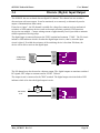
User Manual
605M-R1 Industrial Router &
Device Server
ELPRO Technologies Pty Ltd, 9/12 Billabong Street, Stafford Q 4053, Australia.
Tel: +61 7 33524533 Fax: +61 7 33524577
Email: [email protected]
Web: www.elprotech.com
ELPRO 24 hour Support Help-line America (866) 7134409 Rest of the world +617 3352 5276
605M-R1 Industrial Router
User Manual
Thank you for your selection of the 605M-R1 Industrial Router. We trust it will give
you many years of valuable service.
ATTENTION!
Incorrect termination of supply wires may
cause internal damage and will void warranty.
To ensure your 605M-R1 enjoys a long life,
double check ALL your connections with
the user’s manual
before turning the power on.
Caution!
For continued protection against risk of fire, replace the internal module fuse only with the same type
and rating.
DO NOT:
operate the equipment near electrical blasting caps or in an explosive atmosphere
All equipment must be properly grounded for safe operations. All equipment should be serviced only
by a qualified technician.
Man_605M-R1 Rev 1.0
Page 2
Chapter One
Introduction
Important Notice
ELPRO products are designed to be used in industrial environments, by experienced industrial
engineering personnel with adequate knowledge of safety design considerations.
ELPRO products are designed to operate in the presence of noise and interference, however in an
extreme case, noise and interference could cause product operation delays or operation failure. Like
all industrial electronic products, ELPRO products can fail in a variety of modes due to misuse, age,
or malfunction. We recommend that users and designers design systems using design techniques
intended to prevent personal injury or damage during product operation, and provide failure tolerant
systems to prevent personal injury or damage in the event of product failure. Designers must warn
users of the equipment or systems if adequate protection against failure has not been included in the
system design. Designers must include this Important Notice in operating procedures and system
manuals.
These products should not be used in non-industrial applications, or life-support systems, without
consulting ELPRO Technologies first.
1.
To avoid the risk of electrocution, Ethernet/serial cables and all terminals of the 605M-R1
module should be electrically protected. To provide maximum surge, the module should be
connected to a suitable earth and the module should be installed as recommended in the
Installation Guide.
4.
To avoid accidents during maintenance or adjustment of remotely controlled equipment, all
equipment should be first disconnected from the 605M-R1 module during these adjustments.
Equipment should carry clear markings to indicate remote or automatic operation. E.g. "This
equipment is remotely controlled and may start without warning. Isolate at the switchboard
before attempting adjustments."
5.
The 605M-R1 module is not suitable for use in explosive environments without additional
protection.
Page 3
March 2008
605M-R1 Industrial Router
User Manual
Limited Lifetime Warranty, Disclaimer and Limitation of Remedies
ELPRO products are warranted to be free from manufacturing defects for the “serviceable lifetime” of
the product. The “serviceable lifetime” is limited to the availability of electronic components. If the
serviceable life is reached in less than three years following the original purchase from ELPRO,
ELPRO will replace the product with an equivalent product if an equivalent product is available.
This warranty does not extend to:
-
failures caused by the operation of the equipment outside the particular product's specification,
or
-
use of the module not in accordance with this User Manual, or
-
abuse, misuse, neglect or damage by external causes, or
-
repairs, alterations, or modifications undertaken other than by an authorized Service Agent.
ELPRO’s liability under this warranty is limited to the replacement or repair of the product. This
warranty is in lieu of and exclusive of all other warranties. This warranty does not indemnify the
purchaser of products for any consequential claim for damages or loss of operations or profits and
ELPRO is not liable for any consequential damages or loss of operations or profits resulting from the
use of these products. ELPRO is not liable for damages, losses, costs, injury or harm incurred as a
consequence of any representations, warranties or conditions made by ELPRO or its representatives or
by any other party, except as expressed solely in this document.
CONTENTS
CHAPTER ONE
1.1
INTRODUCTION ............................................................................ 6
NETWORK TOPOLOGY ..................................................................................................... 6
CHAPTER TWO
INSTALLATION ............................................................................... 7
2.1
GENERAL ........................................................................................................................ 7
2.2
POWER SUPPLY ............................................................................................................... 7
2.3
SERIAL CONNECTIONS .................................................................................................... 8
2.3.1
RS232 Serial Port .................................................................................................. 8
2.3.2
RS485 Serial Port .................................................................................................. 9
2.4
DISCRETE (DIGITAL) INPUT/OUTPUT ............................................................................. 10
CHAPTER THREE
OPERATION............................................................................. 11
3.1
DEFAULT CONFIGURATION ........................................................................................... 11
3.2
CONFIGURING THE UNIT FOR THE FIRST TIME ............................................................... 11
3.2.1 Set PC to same network as 605M-R1 ..................................................................... 11
3.2.2 Set 605M-R1 to same network as PC ...................................................................... 12
3.3
NETWORK CONFIGURATION .......................................................................................... 12
3.4
SERIAL PORT CONFIGURATION...................................................................................... 12
3.4.1 Serial Gateway ......................................................................................................... 12
Man_605M-R1 Rev 1.0
Page 4
Chapter One
Introduction
3.4.2 Modbus TCP to RTU Gateway................................................................................ 12
3.5
DIGITAL INPUT/OUTPUT ................................................................................................ 12
3.6
MODBUS I/O TRANSFER ................................................................................................ 12
3.7
MODULE INFORMATION CONFIGURATION ..................................................................... 12
3.8
MESSAGE FILTERING..................................................................................................... 12
CHAPTER FOUR DIAGNOSTICS.................................................................................. 12
4.1
4.2
CONNECTION STATISTICS .............................................................................................. 12
DIAGNOSTICS CHART .................................................................................................... 12
CHAPTER FIVE
SPECIFICATIONS .......................................................................... 12
APPENDIX A FIRMWARE UPGRADE ......................................................................... 12
APPENDIX B
CONNECTION SCENARIOS ................................................................. 12
APPENDIX C UTILITIES ................................................................................................ 12
PING .................................................................................................................................... 12
IPCONFIG ........................................................................................................................... 12
APPENDIX D RS-232 PPP SERVER ............................................................................... 12
APPENDIX E
Page 5
GLOSSARY ............................................................................................... 12
March 2008
605M-R1 Industrial Router
Chapter One
User Manual
INTRODUCTION
The 605M-R1 Industrial Router provides data routing functionality between multiple connected
TCP/IP devices. Since TCP/IP connections are point-to-point only, a number of remote TCP/IP
clients may each connect to the 605M-R1 simultaneously, which can then route data between those
client devices as necessary. More specifically, when connected to a LAN with internet access, the
605M-R1 can be used to route data between remote 605M-D1 GPRS/GSM modems and/or other
Ethernet devices.
The 605M-R1 unit also provides two serial connections (RS-232 and RS-485) as well as a standard
RJ45 10/100Mbps Ethernet connection. It is possible to use all three data connections concurrently,
allowing the 605M-R1 to act as a Device Server. The 605M-R1 also provides several Modbus
protocol features including smart routing of Modbus frames, built-in Modbus RTU and TCP master,
and Modbus TCP to RTU conversion.
1.1
Network Topology
The 605M-R1 is an Ethernet device, and must be configured as part of an Ethernet network. To
enable routing of data between remote GPRS devices, the 605M-R1 must be connected to a LAN
with internet access. Once appropriate internet access is provided, the 605M-R1 can route data
between up to 50 remote GPRS devices and/or Ethernet devices with network access.
In performing the necessary data routing functions relevant to remote GPRS devices, the 605M-R1
acts as a standard TCP/IP server allowing multiple remote devices to connect to the server, and then
routing data between connected devices. The data routing functions provided by the 605M-R1 can
eliminate sending costly data transmissions to unintended remote GPRS devices by using either the
Master/Slave protocol mode or the Modbus aware protocol mode.
Devices can also connect to the 605M-R1 via the on board RS232 or RS485 serial ports using serial
client/server or PPP (point-to-point) protocol. PPP allows the 605M-R1 to connect serial
communications into the Ethernet network.
For illustrated examples of using the 605M-R1 to route date between remote GPRS devices refer to
Appendix B Connection Scenarios.
Man_605M-R1 Rev 1.0
Page 6
Chapter Two
Installation
Chapter Two
INSTALLATION
2.1
General
The 605M-R1 module is housed in an rugged aluminium case, suitable for DIN-rail mounting.
Terminals will accept wires up to 2.5 sqmm (12 gauge) in size.
All connections to the module must be SELV. Normal 110-250V mains supply should not
be connected to any terminal of the 605M-R1 module. Refer to Section 2.3 Power Supply.
Before installing a new system, it is preferable to bench test the complete system. Configuration
problems are easier to recognize when the system units are adjacent.
The foldout sheet 605M-R1 Installation Guide provides an installation drawing appropriate to
most applications. Further information is detailed below.
Each 605M-R1 module should be effectively earthed via the "GND" terminal on the 605M-R1
module - this is to ensure that the surge protection circuits inside the 605M-R1 module are
effective.
2.2
Power Supply
The 605M-R1 module can be powered from a 9 - 30VDC power supply. The power supply
should be rated at 1 Amp. The positive side of the supply must not be connected to earth. The
supply negative is connected to the unit case internally. The DC supply may be a floating supply
or negatively grounded.
The power requirements of the
605M-R1 unit is 240mA @ 12V or
150mA @ 24VDC. This is
inclusive Ethernet port & serial
ports plugged in.
B
9 - 30
VDC
_
+
A
RS485
+
SUPPLY
A Ground Terminal is provided on
COM
605M-R1
the back of the module. This
DIO
Terminal should be connected to
the Main Ground point of the installation in order to provide efficient surge protection for the
module (refer to the Installation Diagram).
Page 7
March 2008
605M-R1 Industrial Router
User Manual
2.3
2.3.1
Serial Connections
RS232 Serial Port
The serial port is a 9 pin DB9 female and provides for connection to a host device as well as a
PC terminal for configuration, field testing and for factory testing. Communication is via
standard RS232 signals. The 605M-R1 is configured as DCE equipment with the pinouts detailed
below.
605M-R1
DB9
MALE
DTE HOST
DB9
FEMALE
605M-R1
DB9
MALE
DCE HOST
DB9
MALE
Hardware handshaking using the CTS/RTS lines is provided. The CTS/RTS lines may be used to
reflect the status of the local unit’s input buffer. The 605M-R1 does not support XON/XOFF.
Example cable drawings for connection to a DTE host (a PC) or another DCE hosts (or modem) are
detailed above.
DB9 Connector Pinouts
Pin
Name
Direction
Function
1
DCD
Out
Data carrier detect –
2
RD
Out
Transmit Data – Serial Data Output
3
TD
In
Receive Data – Serial Data Input
4
DTR
In
Data Terminal Ready -
5
SG
6
DSR
Out
Data Set Ready - always high when unit is powered on.
7
RTS
In
Request to Send -
8
CTS
Out
Clear to send -
9
RI
Signal Ground
Man_605M-R1 Rev 1.0
Ring indicator -
Page 8
Chapter Two
2.3.2
Installation
RS485 Serial Port
The RS485 port provides for communication between the 605M-R1 unit and its host device using a
multi-drop cable. Up to 32 devices may be connected in each multi-drop network.
As the RS485 communication medium is shared, only one of the units on the RS485 cable may
send data at any one time. Thus communication protocols based on the RS-485 standard require
some type of arbitration.
It is important to maintain the polarity of the two RS485 wires. An RS485 network should be
wired as indicated in the diagram below and terminated at each end of the network with a 120
ohm resistor. On-board 120 ohm resistors are provided and may be engaged by operating the
single DIP switch in the end plate next to the RS485 terminals. The DIP switch should be in the
“1” or “on” position to connect the resistor. If the module is not at one end of the RS485 cable,
the switch should be off.
605M-R1
HOST
HOST
120Ω
DIP SWITCH
FOR 120Ω
DIO
SUPPLY
RS485
RS232
ETHERNET
DEFAULTS DIP SWITCH
-
-
120
+
+
+
Ω
RS485 CONNECTION USING TERMINATING RESISTOR
Page 9
March 2008
605M-R1 Industrial Router
User Manual
2.4
Discrete (Digital) Input/Output
The 605M-R1 has one on-board discrete/digital I/O channel. This channel can act as either a
discrete input or discrete output. It can be monitored, or set remotely, or alternatively used to
output a communications alarm status.
If used as an “input”, the I/O channel is suitable for voltage free contacts (such as mechanical
switches) or NPN transistor devices (such as electronic proximity switches). PNP transistor
devices are not suitable. Contact wetting current of approximately 5mA is provided to maintain
reliable operation of driving relays.
The digital input is connected between the "DIO" terminal and common "COM". The I/O circuit
includes a LED indicator which is lit when the digital input is active, that is, when the input
circuit is closed. Provided the resistance of the switching device is less than 200 ohms, the
device will be able to activate the digital input.
V+
DIO
Voltage-free
contact input
GND
V-
605M-R1
The I/O channel may also be used as a discrete output. The digital outputs are transistor switched
DC signals, FET output to common rated at 30VDC 500 mA.
The output circuit is connected to the "DIO" terminal. The digital output circuit includes a LED
indicator which is lit when the digital output is active.
+
Max 30VDC
0.5A
_
Man_605M-R1 Rev 1.0
DC
Load
DIO
GND
605M-R1
Page 10
Chapter Three
Operation
Chapter Three
3.1
OPERATION
Default Configuration
The default factory configuration of the 605M-R1 is
•
IP address192.168.0.1XX, where XX is the last two digits of the serial number (the default IP
address is shown on the printed label on the back of the module)
•
netmask 255.255.255.0
•
Username is “user” and the default password is “user”
The 605M-R1 will temporarily load some factory-default settings if powered up with the
SETUP/RUN switch (on the end-plate of the module) in SETUP position. The previous
configuration remains stored in non-volatile memory and will only change if a configuration
parameter is modified and the change saved.
Do not forget to set the switch back to the RUN position and cycle power at the conclusion
of configuration for resumption of normal operation.
3.2
Configuring the Unit for the First Time
The 605M-R1 has a built-in web server, providing online configuration and diagnostics. The
configuration can be accessed using Microsoft® Internet Explorer. This program is shipped with
Microsoft Windows or may be obtained freely via the Microsoft® website.
Configuration of IP Address, Gateway Address and Subnet Mask may also be accessed via the
RS-232 serial port.
Accessing Configuration for the first time
There are two methods for accessing the configuration inside a 605M-R1. The first method requires
changing your computer settings so that the configuring PC is on the same network as the 605M-R1
with factory default settings. This is the preferred method and is much less complicated than the
second method. You will need a “straight-through” Ethernet cable between the PC Ethernet port
and the 605M-R1. The factory default Ethernet address for the 605M-R1 is 192.168.0.1XX where
XX are the last two digits of the serial number (check the label on the back of the module).
The second method requires setting an IP address in the 605M-R1 such that it is accessible on your
network without having to change your network settings.
3.2.1
Set PC to same network as 605M-R1
Connect the Ethernet cable between unit and the PC configuring the module.
•
Set the SETUP/RUN Switch to the SETUP position. This will start the 605M-R1 with Ethernet
IP address 192.168.0.1XX, subnet mask 255.255.255.0, gateway IP 192.168.0.1. Do not forget
Page 11
March 2008
605M-R1 Industrial Router
User Manual
to set the switch back to the RUN
position and cycle power at the
conclusion of configuration for
resumption of normal operation.
•
Power up the 605M-R1 module.
•
Open “Network Settings” on your PC
under Control Panel. The following
description is for Windows XP earlier Windows operating systems
have similar settings.
•
Open “Properties” of Local Area
Connection.
•
Select Internet Protocol (TCP/IP)
and click on Properties.
Man_605M-R1 Rev 1.0
Page 12
Chapter Three
Operation
•
On the General tab enter IP
address 192.168.0.1,
Subnet mask
255.255.255.0, and default
gateway 192.168.0.1.
•
Open Internet Explorer and ensure that settings will allow you to connect to the IP address
selected. If the PC uses a proxy server, ensure that Internet Explorer will bypass the Proxy
Server for local addresses. This option may be modified by opening Tools -> Internet Options > Connections Tab -> LAN Settings->Proxy Server -> bypass proxy for local addresses.
•
Enter the default IP address for the 605M-R1 http://192.168.0.1XX where XX is the last two
digits of the serial number
•
A welcome webpage should be displayed as illustrated below.
•
Configuration and Diagnostics may be opened by clicking on any of the menu items, and
entering the username “user” and default password “user”. Configure the unit to your
requirements (refer later sections of this manual).
When Configuration is complete, switch SETUP/RUN switch on 605M-R1 to RUN position, and
cycle power to resume normal configured operation.
Page 13
March 2008
605M-R1 Industrial Router
3.2.2
User Manual
Set 605M-R1 to same network as PC
This is the alternate procedure to setting an IP address in the 605M-R1. Consult your network
administrator for an IP address on your network, the gateway IP address, and network mask.
a)
Switch the SETUP/RUN switch on 605M-R1 to SETUP position.
b) Connect the RS232 port on the 605M-R1 to the RS232 port on the PC using a “straightthrough” serial cable.
c)
Open a terminal package (such as Hyperterminal) with 19200bps data rate, 8 data bit, 1 stop, no
parity and no flow control. Make sure that no other programs have control of the serial port.
Man_605M-R1 Rev 1.0
Page 14
Chapter Three
Operation
d) Power up 605M-R1. Basic network settings will be displayed on the terminal as illustrated
below. When prompted, hit enter key to stop automatic boot process. You have 5 seconds to
abort the boot process.
My Right Boot 2.1
Copyright 1999-2004 Cybertec Pty Ltd, All rights reserved.
This software is provided by Cybertec ``as is'' and with NO
WARRANTY.
http://www.cybertec.com.au/
ROM :
RAM :
256KB @ 0xffe00000
8192KB @ 0x00000000 (143KB / 0x00023d8c)
ROM Configuration table ... PASSED.
RAM address pattern check . PASSED.
RAM address bus check ..... PASSED.
Product
Variant
Serial No.
Release
Released date
Released host
Build date
Build host
Boot Flags
:
:
:
:
:
:
:
:
:
Boot
Boot
Boot
Boot
Boot
Boot
Boot
:
:
:
:
:
:
:
delay
Filename
Address
Netmask
Gateway
Host
Mac 0
E24g
605MR1
10050004 - 1105xxx0004
epm_mrb_elpro_E24g_1.64
1 June 2006
Anxosity
Mon May 29 11:39:56 2006
Anxosity
no RAM test, no ROM test, bus timer on, wdog on
static IP, auto-boot, net-boot, reset on
local file, no binary load
2
/memory/0xffe40000,0xc0000
192.168.0.219
255.255.255.0
192.168.9.4
192.168.9.220
00:12:af:00:07:9f
RTE data store .... no error
Setting bus timer (on) and watchdog (on) ... PASSED
802.11 Interface Power ON...
Reset 802.11 Interface...
Checking 802.11 NIC (Base Address: 0x30000000)
Register Read-Write Test...Failed: register = 1, test value = 0
Recovery Configuration :
ip address : 192.168.0.104
net mask
: 255.255.255.0
gateway
: 192.168.0.1
host
: 192.168.0.1
eip: mount point /memory
fec0: connected at 100M Full Duplex.
fec0: local ip = 192.168.0.104, server ip = 192.168.0.1
Press ENTER to abort automatic booting ... 5
Page 15
March 2008
605M-R1 Industrial Router
User Manual
e)
Check values for Boot Address, Boot Netmask, and Boot Gateway. These values should be set
to reflect those of the PC you are using to configure the unit. If these are correct skip to step (h).
You may check settings again with the rct command. For further help, type the help command.
f)
Set Boot Netmask to the same settings as the computer you have the Ethernet cable connected
to. This may be performed with the command: bnm <Type the netmask>
g) Set Boot Gateway to the same settings as the computer you have the Ethernet cable connected
to. This may be performed with the command: bgw <Type the gateway IP address>
h) Choose an IP address for the 605M-R1 being upgraded. This IP address must be on the same
network as the computer you have connected the Ethernet cable to. This may be performed with
the command: bip <Type the IP address>
i)
Switch SETUP/RUN switch on 605M-R1 to RUN position.
j)
Type the command reset, or cycle power to the unit. The 605M-R1 will reset and start with the
network settings you have entered.
k) Open Internet Explorer and ensure that settings will allow you to connect to the IP address
selected. If the PC uses a proxy server, ensure that Internet Explorer will bypass the Proxy
Server for local addresses. This option may be modified by opening Tools -> Internet Options > Connections Tab -> LAN Settings->Proxy Server -> bypass proxy for local addresses.
l)
Enter the webpage http://xxx.xxx.xxx.xxx/ where xxx.xxx.xxx.xxx is the IP address selected for
the module. A welcome webpage should be displayed as illustrated.
m) Clicking on any of the menu items, and entering the username “user” and password “user” may
open Configuration and Diagnostics. If the password has previously been configured other than
the default password, then enter this instead.
Man_605M-R1 Rev 1.0
Page 16
Chapter Three
Operation
3.3
Network Configuration
You can view or modify Ethernet network parameters by selecting the “Network Settings” menu.
When prompted for username and password, enter “user” as the username, and “user” as the
password in the password field. If IP address or password has been forgotten, the SETUP/RUN
switch may be used to access the existing configuration. Refer to section 3.1 above.
The Network Configuration page allows configuration of parameters related to the wired Ethernet
interface. In general, IP address selection will be dependant upon the connected wired Ethernet
device(s) – before connecting to an existing LAN consult the network administrator.
TCP/IP Configuration Fields
MAC Address
This is the unique hardware address of the 605M-R1, assigned in
the Factory. For the majority of systems, this item should not be
changed.
IP Address
The IP address of the 605M-R1 on its wired Ethernet port.
Subnet Mask
The network mask of the 605M-R1 on its Ethernet port.
Default Gateway
This IP address of the Gateway which connects to devices beyond
the LAN, i.e. Internet access.
Keepidle
This is the time (in seconds) before the first keepalive probe is sent
on a given TCP/IP connection (if keepalive probes are enabled for
that connection).
Keepintvl
This is the interval (in seconds) between successive keepalive probes
on a given TCP/IP connection. If 8 successive keepalive probes are
sent with no response, the connection is dropped.
The 605M-R1 is primarily a TCP/IP Routing Server, to which a number of external TCP/IP Clients
(typically 605M-D1 GPRS modems) may connect. Since TCP/IP connections are point-to-point
only, a number of remote TCP/IP clients may each connect to the 605M-R1 simultaneously, which
can then route data between the separate remote client devices as necessary.
In order to route data between connected devices efficiently, the 605M-R1 would need to have
detailed knowledge of the protocol comprising that data. Alternatively, if the protocol is not known
by the module, then any data frame arriving from a given device can simply be forwarded to all
other devices (i.e. broadcast). The 605M-R1 Routing Server functionality supports a Modbus RTU
protocol aware routing mode, a generic master/slave protocol mode, and a broadcast mode.
The example below illustrates the type of topology that would typically be used in conjunction with
the 605M-R1 – that is, a number of remote GPRS modems connecting to the 605M-R1, whose job
it is to route data between those devices. In the example, a server located on a corporate LAN uses
port forwarding to forward TCP/IP data arriving from remote GPRS modems to the 605M-R1. In
this case, the fixed IP address of the 605M-R1 is used by the server for port forwarding, whereas the
Page 17
March 2008
605M-R1 Industrial Router
User Manual
remote GPRS modems connect to the server using a domain name and TCP port number.
Alternatively, the need for a separate server performing port forwarding can be eliminated by
obtaining a public IP address for the 605M-R1, a possibility which is normally expensive and less
flexible than the previous option. For further examples see Appendix B Connection Scenarios.
605M-D1
Modem
RS232
Device
A
605M-R1
Router
Internet
GPRS Connections
605M-D1
Modem
RS232
Device
B
LAN
605M-D1
Modem
RS232
Device
N
As mentioned earlier, there are 3 modes of operation that the 605M-R1 can use to route data
between the connected devices:
1) Protocol Aware Routing. If the 605M-R1 is aware of the protocol used by the remote
devices then it can efficiently route data only to the required location based on the
addressing inherent in that protocol. The 605M-R1 currently supports the Modbus RTU
protocol. When this mode is used, the 605M-R1 initially has to learn the location of slave
devices by broadcasting requests to unknown slave devices. However, once the slave device
responds it’s location is learnt, and an entry is made in the internal routing table so that
subsequent data directed at that slave device is sent only on the desired remote device
connection.
2) Master/Slave Routing. If the protocol used by the remote devices is a Master/Slave type
protocol (i.e. a single master device requests data transfers with slave devices), but is a
protocol other than Modbus RTU, then data being sent by the master device is broadcast to
all connected slave devices since the router can not know the required destination without
knowledge of the protocol. However, data being sent by any slave device is always routed
only to the master device.
3) Broadcast Mode. If the protocol being used by the remote devices is not a master/slave type
protocol – then data being sent by any remote device can be broadcast to all other connected
remote devices. This is the least efficient mode in terms of data transfer, however may be
suitable for point-to-point or small multipoint systems, or in cases where the amount of data
being transferred is small.
The 605M-R1 can route data between up to 10 separate groups of remote devices using any of the 3
modes described above for any group. These Routing Servers can be configured on the Network
Settings configuration web page. The current module firmware can support a maximum of 50
remote devices connected to the 605M-R1 in total. If at least one master and one slave device are
Man_605M-R1 Rev 1.0
Page 18
Chapter Three
Operation
connected to a Routing Server in Master/Slave mode – or at least two devices are connected to a
Routing Server in broadcast mode, the Link LED will be illuminated; otherwise the link LED will
be off. The link status for each Routing Server is also available in onboard Modbus status registers
(see Modbus I/O Transfer section), and comprehensive connection statistics are available online via
the Statistics configuration web page.
Routing Server Configuration Fields
Master Port
When a master/slave protocol is to be used by remote devices,
specify the TCP Port number on the 605M-R1 that the master device
will connect to. Set this field to 0 if there is no master device.
Slave Port
Specify the TCP port number on the 605M-R1 that non-master
remote devices will connect to.
Max Connections
Enter the maximum number of devices that are allowed to connect to
this Routing Server (default is 32, maximum is 50).
Modbus Mode
If the remote devices are communicating using the Modbus RTU
protocol, select this option to enable the 605M-R1 to route Modbus
data frames to the correct location.
Max Poll Fail
When Modbus Mode is enabled, enter the maximum number of
times a slave device may fail to respond to a master request before
that slave address is removed from the internal Modbus routing
tables (and it’s location must therefore be rediscovered using
broadcast messages). Enter 0 if entries in the routing table are never
to be cleared.
Inactivity Timeout
Enter the time, in seconds, after which if no data has been sent or
received on any remote device connection to this routing server then
that connection will be closed. Enter 0 if an inactivity timeout is not
required.
Send Keepalive
TCP/IP messages can be used to maintain the status of inactive
remote device connections as an alternative to an inactivity time. If
this option is enabled then TCP keepalive probes will be sent on idle
connections after the configurable Keepidle and Keepintvl times (see
the TCP/IP Configuration Fields table above).
Password
For added security, remote devices can be required to provide a
password in order to connect to the 605M-R1. Enter the password
here or leave blank if no password is required.
Each of the 3 Routing Server modes of operation is illustrated in the example configuration below
where it can be seen that 3 separate Routing Servers have been configured (note that in the majority
of actual applications that only 1 Routing Server would normally be configured per 605M-R1). The
first entry uses the Modbus aware protocol mode, the second entry uses the generic Master/Slave
mode, and the final entry uses Broadcast mode. We will take a closer look at the configuration of
each entry below.
Page 19
March 2008
605M-R1 Industrial Router
User Manual
Looking at the first entry in the example above a Routing Server has been configured to operate in
the Modbus aware protocol mode. The Master Port is set to 5001, so the remote TCP/IP client
device where the Modbus Master is located must connect to TCP Port 5001 of the 605M-R1. The
Slave Port set to 5002, so that all remote TCP/IP client devices where Modbus Slaves are located
must connect to TCP Port 5002 of the 605M-R1. Max connections are set to 10 meaning that a total
of 10 remote TCP/IP clients may connect to this Routing Server. Modbus Mode is selected so that
the 605M-R1 can route Modbus frames directly to their intended destination. Max Poll Fails is set
to 5 – meaning that if 5 consecutive Modbus requests directed to a particular Modbus Slave fail to
get a response then the routing table entry for that slave device will be deleted. Inactivity Timeout is
set to 0, so that Inactivity Timeouts will not apply for this Routing Server. Similarly Keepalive
messages are not sent on inactivity. Finally a password has not been specified, meaning that any
remote TCP/IP client may connect to this Routing Server.
The second entry in the example has been configured to operate in the generic Master/Slave
protocol mode. The main difference between the configuration of this entry, and that of the Modbus
aware server configured in the first entry, is that the Modbus Mode option is not selected.
Consequently the Max Poll Fail parameter cannot apply when the specific protocol is unknown and
is therefore set to zero. Finally, since the protocol is some sort of a generic Master/Slave type, we
specify the Master Port as the port that the remote Master must connect to, and the Slave Port as the
port that all remote slave devices must connect to. Data arriving at the Master Port will then be
broadcast to all devices connected to the Slave Port, whereas data arriving at the Slave port will be
forwarded to the Master Port only.
The third and final entry in the example above configures a Routing Server to operate in broadcast
mode. Only a Slave Port is configured in this case, and this is the TCP Port number of the 605M-R1
that all remote devices must connect to. Data arriving from any remote device will then be broadcast
to all other devices that are connected to this port.
Man_605M-R1 Rev 1.0
Page 20
Chapter Three
3.4
Operation
Serial Port Configuration
The 605M-R1 has an RS-232, and RS-485 port for serial communications. The 605M-R1 offers
three different serial functions which are Serial Gateway, Modbus TCP to RTU Gateway, and PPP
server. The PPP Server is made available for legacy devices – details on PPP Server configuration
can be found in Appendix C. Serial port configuration may be performed via the Serial Ports
configuration web page.
3.4.1
Serial Gateway
Serial Gateway functionality is available for both RS-232 and RS-485 ports independently, and
enables serial data to be routed via the wired LAN. The implemented serial gateway functionality
allows point-to-point and multipoint serial data transfer.
Each 605M-R1 serial port may be configured as Server, Client, or Multicast Group. When
configured as Server, the module will wait for a connection to be initiated by a remote client. When
configured as Client, the module will automatically attempt to connect to the specified remote
server. When configured as Multicast Group, the module will broadcast data to all members of the
same Multicast Group.
The most common use for the serial gateway functionality in the 605M-R1 is to connect the local
serial port(s) to a Routing Server in order to exchange data with remote GPRS modems. The
example configuration below illustrates how to configure the local RS232 port to connect to a
Routing Server (for details on how to configure a Routing Server refer to the previous section titled
Network Configuration).
Page 21
March 2008
605M-R1 Industrial Router
User Manual
It can be seen that we enable the RS232 serial gateway and select client mode to connect to the local
Routing Server. We specify the special loopback IP Address of 127.0.0.1 for Remote Device IP
Address, which simply means that we are connecting internally to our own IP Address since the
Routing Server is local to the same module (alternately we could have explicitly specified our own
fixed IP Address). For Remote Device Port we specify the corresponding port on the Routing Server
that we wish to connect to (i.e. Master Port or Slave Port). Data arriving on the RS232 port will then
be routed in the same way as data on any remote device connection to the Routing Server. A
complete description of all possible Serial Gateway settings is provided in the table below.
Serial Gateway Settings:
Enable Serial Gateway
Check this box to enable Serial Gateway Server on the specified
serial port.
Data Rate
Specify the serial baud rate. Serial data rates available range from
110bps to a maximum of 230,400bps.
Data Bits Parity Stop Bits
The data format desired. Data formats of 8N1, 7E1, 7O1, 7E2,
7O2 are supported.
Character Timeout
Enter the maximum time allowed to elapse (in msec) between
received serial characters before packet is sent via the network.
Packet Size
Enter the maximum number of received serial characters that can
be buffered before the packet is sent on the network.
Server
When configured as Server, the module will wait for a TCP/IP
connection to the serial port to be initiated by a remote client.
Listen Port
Server Only. Enter the TCP port number on which the server must
listen for incoming connections.
Client
When configured as Client, the module will automatically attempt
to connect to the specified server.
Remote Device Port
Client only. Enter the TCP port number of the remote server (i.e.
the remote port to automatically connect to).
Remote Device IP
Address
Client only. Enter the IP Address of the remote server (i.e. the
remote IP Address to automatically connect to).
Multicast Group Port
Enter the UDP port number that all members of the group will use
(i.e. all group members should use the same port number).
Multicast Group IP
Enter a valid Multicast IP Address identifying the group (i.e. all
group members should use the same Multicast Group IP Address).
Valid Multicast IP Addresses are in the range 224.0.1.0 to
238.255.255.255.
Man_605M-R1 Rev 1.0
Page 22
Chapter Three
3.4.2
Operation
Modbus TCP to RTU Gateway
The Modbus TCP to RTU Gateway allows an Ethernet Modbus TCP Client (Master) to
communicate with a serial Modbus RTU Slave directly connected to either the onboard RS485 or
RS232 port. The Modbus TCP to RTU Gateway can not be configured for the RS232 and RS485
ports at the same time. When enabled, the Modbus TCP to RTU Gateway will accept TCP/IP
connections on well known Modbus TCP Port 502.
Enable RS-232 Modbus
TCP to RTU Gateway
Enable RS-485 Modbus
TCP to RTU Gateway
Data Rate
Data Bits Parity Stop Bits
Pause Between Requests
Response Timeout
Connection Timeout
Maximum Request Retries
Maximum Connections
Page 23
Check this box to enable the Modbus TCP to RTU Gateway on the RS232 port. Only a single serial port is allowed at a time.
Check this box to enable the Modbus TCP to RTU Gateway on the RS485 port. Only a single serial port is allowed at a time.
The serial data rate desired. Serial data rates available range from
110bps to a maximum of 115,200bps.
The data format desired. Data formats of 8N1, 7E1, 7O1, 7E2, 7O2 are
supported.
Enter the delay between serial request retries in milliseconds
Enter the serial response timeout in milliseconds – a serial retry will be
sent if a response is not received within this timeout.
Enter the TCP connection timeout in seconds – if no Modbus/TCP data
is received within this timeout then the TCP connection will be
dropped. Set this field to zero for no timeout.
Enter the maximum number of request retries performed serially.
Enter the maximum number of simultaneous TCP connections to the
server allowed.
March 2008
605M-R1 Industrial Router
3.5
User Manual
Digital Input/Output
The functionality of the shared Digital Input/Output pin may be configured via the “Modbus I/O”
configuration webpage. As this pin is shared, the Digital Input status will be ON when the Digital
Output is set ON.
The status of the onboard Digital I/O can also be transferred to/from another device using Modbus
(see section “3.6 Modbus I/O Transfer” below) or it can be configured to provide status of the
module communications.
3.6
Modbus I/O Transfer
The 605M-R1 provides Modbus TCP and RTU Client and Modbus TCP Server functionality for I/O
transfer. 5000 x 16bit general purpose registers are provided for Modbus (including the onboard
Digital Input/Output) and are shared for both Client and Server. Modbus Client (Master) and
Modbus TCP Server (Slave) are both supported simultaneously, and enable the 605M-R1 to transfer
I/O to/from almost any combination of Modbus TCP or RTU devices.
The layout of the 605M-R1 internal I/O Registers is summarized in the table below. Each register is
internally saved as a 16 bit value. A Modbus transaction may access the entire 16 bit value of any
register, or alternatively the most significant bit of a register may be accessed as a discrete value.
The main use for the general purpose I/O registers is for intermediate storage, i.e. when transferring
I/O from one Modbus Slave device to another. Also provided is the status of the onboard digital I/O,
as well as the link status of connections to the Routing Server. The 16 bit status registers will
contain the value FFFF(hex) for ON and 0000(hex) for OFF. Inverted status registers are also
provided where the registers contain 0000(hex) for ON and FFFF(hex) for OFF.
Man_605M-R1 Rev 1.0
Page 24
Chapter Three
Operation
Registers
Purpose
1 – 4299
General purpose I/O registers (read/write)
4300
On-board Digital Input value (read only)
4301
Link LED Status (read only)
4320
On-board Digital Output value (read/write)
4370
On-board Digital Input inverted value (read only)
4371
Link LED Status inverted (read only)
4500-4509
Link Status for Routing Servers 1-10 respectively
4550
Connection Status for Routing Server 1, Master Port
4551
Connection Status for Routing Server 1, Slave Port
4552-4569
Connection Status for Routing Servers 2-10, Master and
Slave Ports respectively
4600-4659
Inverted values of registers 4500-4569 respectively
Modbus Client (Master) enables the 605M-R1 to connect to one or more Modbus TCP or RTU
Servers (Slaves). All Modbus Master messages are directed either to/from the onboard I/O registers
depending on configuration (described below). Modbus Client functionality allows connections to a
maximum of 25 different TCP/IP Servers. The built in Modbus Master may be configured to
transfer either Modbus TCP or Modbus RTU data frames. In the case of Modbus RTU the intended
slave device would typically be connected to a Routing Server Slave Port.
Modbus TCP Server (Slave) enables the 605M-R1 to accept connections from one or more Modbus
TCP Clients (Masters). All Modbus transactions routed to the onboard Modbus TCP Server are
directed either to or from the onboard general purpose I/O registers. The Modbus TCP Server is
shared with the Modbus TCP to RTU Gateway, so that the Modbus “Device ID” is used to
determine if a Modbus transaction is to be routed to the onboard Modbus TCP Server or to a
Modbus RTU device connected to the serial port. Care should therefore be taken that all Modbus
devices connected to the local serial port use a different Modbus Device ID (i.e. Modbus Slave
Address) to the onboard Modbus TCP Server. Up to 32 separate connections to the Modbus TCP
Server are supported.
The 605M-R1 provides a configurable option to automatically reset the value of the onboard I/O
registers to zero in the event of a communications failure. If a valid Modbus transaction directed
to/from a given register has not been completed for longer than a configurable timeout, then the
value of that register will be reset to zero.
The example below illustrates how to configure the 605M-R1 to act as a Modbus Master and
transfer 5x16 bit registers between two Modbus Slave devices. Each of the Modbus Slave devices
are connected via 605M-D1 GPRS modems to the Slave Port of a Routing Server, therefore the
Modbus Master configuration is directed at the Master Port of this local Routing Server (see section
Page 25
March 2008
605M-R1 Industrial Router
User Manual
3.3 Network Configuration for further details on Routing Server operation). The topology of the
system described in this example is also illustrated as Scenario 1 in Appendix B: Connection
Scenarios.
From the screen shot above it can be seen that we have enabled the Modbus Client (Master) and
have configured a scan rate of 30 seconds, meaning that the master will send a request (i.e. as
configured in Modbus Client Mappings) every 30 seconds.
To actually transfer the required 5 registers from one remote Modbus Slave device to another, we
will need to configure two Modbus Client Mappings. The first mapping will read the 5 input
registers from the first remote device and store them in the internal general purpose registers of the
605M-R1. Next we configure a second mapping to send the contents of those 5 internal registers
(which will now contain a copy of the remote device registers) to the second remote device.
Looking at the first mapping above it can be seen that we are reading registers 1-5 from the remote
Modbus Device ID 1 into our own local registers 1-5. The Server IP Address we specify is the
special loopback IP Address 127.0.0.1 because we are connecting to the local Routing Server which
will then route the Modbus message to the appropriate remote device. Likewise the TCP Port we
specify for the mapping is the Master Port of the local Routing Server. The protocol is RTU since
the remote devices we are polling are Modbus RTU Slaves, and the response timeout is set to
10seconds which is how long we will wait for a response from the slave device.
Man_605M-R1 Rev 1.0
Page 26
Chapter Three
Operation
Looking at the second mapping, we now take the 5 local registers 1-5 (that we read into in the first
mapping) and write these registers to Modbus Device ID 2 registers 1-5. As with the first mapping,
we specify IP Address and TCP Port corresponding to the Master Port of the local Routing Server.
Modbus Configuration Fields:
Enable Modbus TCP Server
(Slave)
Modbus Server Device ID
Enable Modbus Client
(Master)
Modbus Client Scan Rate
Reset Registers on Comm’s
Fail
Comms Fail Timeout
Check this box to enable the onboard Modbus TCP Server. All Modbus
TCP connections to the module IP Address and specified Modbus
Server Device ID will be routed to the onboard I/O registers.
Specify the Modbus Device ID for the onboard Modbus TCP Server.
Allowed values are 0 to 255.
Check this box to enable the onboard Modbus Client. I/O to be
transferred via the Modbus client is specified with Modbus Client
Mappings.
Enter the delay (in milliseconds) between the execution of consecutive
Modbus Client Mappings to the same Server.
When Enabled the value in any onboard I/O register will be reset to zero
if a valid Modbus transaction directed to/from the given register has not
been completed for longer than the Comms Fail Timeout.
The period of time after which onboard I/O registers will be reset if a
valid Modbus transaction directed at that register has not completed.
Modbus Client Mapping Fields:
Local Register
I/O Count
Function Code
Destination Register
Device ID
Server IP Address
Response Timeout
Comm Fail Register
Protocol
Port
Page 27
Enter the starting onboard I/O register number that the specified
Modbus Master transaction will transfer I/O to/from.
Specify the number of consecutive I/O register to be transferred for the
specified transaction.
Specify the Modbus Function Code for the transaction.
Enter the starting I/O register number in the destination device that the
specified Modbus Master transaction will transfer I/O to/from.
Enter the Modbus Device ID of the destination Modbus device
Specify the IP Address of the destination TCP/IP Server for the
specified transaction.
Enter the timeout (in milliseconds) to wait for a response to the
specified transaction.
Enter the onboard I/O Register number to store the communication
status of the specified transaction. The Specified register will be set to 0
if communications is successful, 0xFFFF if there is no connection to the
specified server, or 0xFFxx where xx is the Modbus Exception Code
Specify the whether the data frame sent to the specified server will be
Modbus TCP or Modbus RTU
Specify the TCP Port number of the destination TCP/IP server. Modbus
TCP Servers normally use port 502.
March 2008
605M-R1 Industrial Router
3.7
User Manual
Module Information Configuration
Module Information Webpage Fields
This configuration page is primarily for information purposes. With the exception of the password,
the information entered here is displayed on the root webpage of the 605M-R1.
Password
When changing the password on this screen, it will be sent
unencrypted over any wired network.
Device Name
A text field if you wish to label the particular 605M-R1.
Owner
A text field for owner name.
Contact
A text field for owner phone number, email address etc.
Description
A text field used for a description of the purpose of the unit.
Location
A text field used to describe the location of the 605M-R1.
Man_605M-R1 Rev 1.0
Page 28
Chapter Three
3.8
Operation
Message Filtering
The 605M-R1 may be configured to reject or accept messages to and from certain Addresses. To
accept messages from particular devices a “Whitelist” of Addresses must be made. Alternatively to
reject messages from particular devices, a “Blacklist” of Addresses must be made.
The Filter comprises of two lists: one of MAC Addresses and another listing IP protocol details.
Each list may be set as either a blacklist (to block traffic for listed devices and protocols), or as a
whitelist (to allow traffic for listed devices and protocols). The Filter operates on two rules listed
below.
1. A Blacklist has priority over a whitelist. Traffic matching detail in a blacklist will be discarded if
it also appears in a whitelist.
2. When one or both lists are whitelists, traffic must have matching detail in at least one of the
whitelists for it to be passed. Note that, as this must agree with rule 1 above, the traffic detail must
not match anything in a blacklist, if present, for it to be passed.
When configuring a Whitelist it is important to add the Addresses of all devices connected to the
605M-R1 wired Ethernet port. It is particularly important to add the Address of the configuration
PC to the Whitelist. Failure to add this address will prevent the configuration PC from making any
further changes to configuration. Design of the filter may be simplified by monitoring network
traffic and forming a profile of traffic on the wired network. Network Analysis software, such as
the freely available Ethereal program, will list broadcast traffic sent on the network.
It is advisable to use the Apply Changes button to test the configuration entered. Once the
configuration is determined to be correct, the Apply Changes and Save button should be used. In
the event that the configuration is incorrect, a power reset will revert the unit to previously saved
configuration.
If an erroneous configuration has prevented all access to the module, SETUP mode may be
used analyze what is wrong with the configuration. Simply switch the dipswitch to SETUP and
cycle power. The 605M-R1 will retain its configuration, however will load up at IP address
192.168.0.1XX, netmask 255.255.255.0 with the filter disabled. The XX in the IP address is the last
two digits of the serial number. Configuration webpages will still show the original configuration.
No changes are made to configuration until the user saves changes. To resume normal operation, set
the dipswitch to RUN and cycle power.
Page 29
March 2008
605M-R1 Industrial Router
User Manual
MAC Address Filter Configuration:
Add Entries
Enter the MAC addresses of devices to be added to the list. Multiple
entries must be separated by a semi-colon (;).
Delete Entries
Check the box alongside entries selected for removal from the list.
Whitelist or Blacklist
Check the box to make the list a whitelist. This will allow devices
with the MAC addresses listed to communicate with the module. All
other devices are blocked unless they exist in an IP whitelist.
Uncheck the box to make the list a blacklist. This will prevent all
listed devices from using or accessing the module.
Apply Changes
Update settings.
Apply Changes and Save
Update settings and save to non-volatile memory.
IP Address Filter Configuration:
Add Entries
Enter the details of IP traffic to be added to the list. Protocols ARP,
ICMP, TCP and UDP may be selected. Other IP protocols may be
selected provided the IP protocol number within packets is known.
TCP and UDP traffic may be also limited to specific port numbers.
Delete Entries
Check the delete box alongside entries selected for removal from the
list. Alternatively, check the enable box alongside entries if you want
to make the rule active.
Whitelist or Blacklist
Check the box to make the list a whitelist. This will only allow
traffic described in the list to communicate with the module. All
other traffic is blocked unless it is present in a MAC whitelist.
Uncheck the box to make the list a blacklist. This will ban all traffic
described in the list from being sent to the module.
Apply Changes
Update settings.
Apply Changes and Save
Update settings and save to non-volatile memory.
NOTE: When configuring a TCP filter it is often desirable to also configure both an ARP and an
ICMP filter for the same IP Address range. The ARP filter is required whenever the sending device
does not have a fixed IP to MAC Address translation table entry (i.e. whenever the device may need
to send an ARP request to determine the MAC address of a device with a known IP Address). An
ICMP filter is needed to allow/disallow “pings”.
Man_605M-R1 Rev 1.0
Page 30
Chapter 4
Chapter Four
4.1
Diagnostics
DIAGNOSTICS
Connection Statistics
The statistics web page of the 605M-R1 can be used to view comprehensive connection statistics
for any configured Routing Servers and the correspondingly connected remote GPRS devices.
Internal buffer and memory statistics are also available.
The screenshot below shows the TCP/IP Connection Statistics for a Routing Server configured in
Modbus protocol mode (refer 3.3 Configuration Statistics for configuration information). In this
example there are two Modbus Slave devices connected via a single remote GPRS Modem to the
605M-R1 (refer Appendix B Connection Scenarios: Scenario 2 for a connection diagram of a
similar system). In this example the Modbus Master is serially connected to the 605M-R1 via the
local RS232 port.
As can be seen in the screenshot, many useful statistics are available, including remote device IP
Address, number of bytes transmitted and received on each connection, number of valid Modbus
frames transmitted and received on each connection, which Modbus Device ID’s are connected to
each remote device, and the amount of time that each connection has been active for.
Page 31
March 2008
605M-R1 Industrial Router
User Manual
4.2
Diagnostics Chart
LED Indicator
Condition
Meaning
OK
GREEN
Normal Operation
OK
RED
Supply voltage too low
LINK
On
At least one Routing Server has 2
connected devices suitable for data to be
routed between
LINK
Off
No configured Routing Servers have a link
LAN
ON
Link Established on Ethernet port
LAN
Flash
Activity on Ethernet port.
Serial
GREEN flash
Rs232 Serial Port Activity
Serial
RED flash
Rs485 Serial Port Activity
DIO
On
Digital Output ON or Input is grounded.
DIO
Off
Digital Output OFF and Input is open circuit.
ALL
Flashing in sequence
Module Boot-up. Refer to chart below.
The green OK LED on the front panel indicates correct operation of the unit. This LED turns red on
failure as described above. When the OK LED turns red shutdown state is indicated. On processor
failure, or on failure during startup diagnostics, the unit shuts down, and remains in shutdown until
the fault is rectified.
Boot Loader LED Indication during Startup
Serial
LAN
LINK
ACTIVE
Comment
Orange
Orange
Orange
RED
Initial Power Up & bootload Initialisation
RED
Orange
Orange
RED
Check Config & Print Sign-on message (If boot delay not
zero)
Orange
Orange
Orange
RED
Print Configuration Table to terminal (If boot delay not zero)
Green
LAN
Off
RED
Initialise Networking and Start Auto Boot sequence
Orange
LAN
Off
GREEN
Wait for <ENTER> to abort Auto boot (If boot delay not
zero)
Sequence
LAN
Sequence
GREEN
Boot – loader active (auto boot aborted or no application)
SERIAL
LAN
LINK
GREEN
Normal Operation. Application Running.
Man_605M-R1 Rev 1.0
Page 32
Chapter 4
Diagnostics
Chapter Five
SPECIFICATIONS
General
EMC
specification
EN 300 683
FCC Part 90
Housing
114 x 140 x 30mm
Powder-coated, extruded aluminium
4.5 x 5.5 x 1.2 inch
DIN rail mount
Terminal blocks
Removable
Suitable for 12 gauge (2.5sqmm)
conductors
LED indication
Active, Serial RX and TX, Link
Operating
Temperature
-40 to +60 degrees C
0 – 99% RH non-condensing
-40 to +140 degrees F
Power Supply
Nominal supply
9 to 30VDC
Overvoltage and reverse voltage
protected
Average current
drain
240 mA @ 12V
150mA @ 24VDC
Ethernet Port
10/100 BaseT
RJ45
Standard
IEEE 802.3 compliant
Serial Ports
RS232 Port
DB9 female DCE
RTS/CTS/DTR/DCD hardware signals
provided
RS485 Port
2 pin terminal block
Max distance 4000’ / 1.2 km
Data rate (bit/sec) 1200, 2400, 4800, 9600, 14400,
- configurable
19200, 38400, 57600, 76800,
115200, 230400
7 or 8 data bits, Stop/start/parity bits
configurable
System
Parameters
User
Configuration
Page 33
Via embedded web page
March 2008
605M-R1 Industrial Router
Appendix A
User Manual
Firmware Upgrade
Determine which firmware version is present in the module to be upgraded by viewing the index
webpage of the module.
Firmware may be upgraded via the configuration web pages. This upgrade can be done locally with a
PC connected directly to the module, or remotely via the network. Please follow these steps to
upgrade the unit.
1. Place the new application firmware file epm_605MR1_x.x.bin.gz on the computers hard drive.
Ensure that the file is not placed in a deeply nested folder.
2. Open internal webpage of unit to be upgraded, and Select System Tools from Menu
3. Select Firmware upgrade from the System Tools menu.
4. Click Browse button and find the application firmware file on your computer. Ensure that
the file is not in a deeply nested folder, as there is a character limitation of the filename
and path.
5. There are two options:
a. The “Save to Flash and Reset” button may be clicked, to initiate a reset
immediately after a successful firmware upgrade so that the new firmware is run.
b. Alternatively, Click “Save to Flash” button to just program the new firmware to
the unit. A reset is necessary to run the new firmware.
Man_605M-R1 Rev 1.0
Page 34
Chapter 4
Diagnostics
6. The following dialog box may be displayed as a warning. Click OK to proceed.
When upgrade is completed, the System Tools webpage will be shown if “Save to Flash”
was clicked. If “Save to Flash and Reset” was clicked, the unit will display a message
that the module is resetting.
Firmware upgrade is now complete.
Page 35
March 2008
605M-R1 Industrial Router
User Manual
Appendix B
Connection Scenarios
Man_605M-R1 Rev 1.0
Page 36
Chapter 4
Page 37
Diagnostics
March 2008
605M-R1 Industrial Router
Man_605M-R1 Rev 1.0
User Manual
Page 38
Chapter 4
Appendix C
Diagnostics
Utilities
PING
Ping is a basic networking program that lets you verify that a particular IP address exists and can
accept requests. Ping is used diagnostically to ensure that a host computer you are trying to reach
is actually operating. If, for example, a user can't ping a host, then the user will be unable to send
files to that host. Ping operates by sending a packet to a designated address and waiting for a
response. The basic operation of Ping can be performed by following these steps in any Windows
operating system.
Click on the Start Menu and select Run. Type in “cmd” and enter, you should then see the
command screen come up. There will be a certain directory specified (unique to your own PC)
with a flashing cursor at the end. At the cursor type the word “ping” leaving a space and the
default IP address for the 605M-R1 at first startup.
This command would be written as Ping 192.168.123.123 then Enter to send the ping command.
The PC will reply with an acknowledgement of your command and if your 605M-R1 is correctly
configured your reply will look something like this.
The screen shot below shows the response of the “ping 192.168.123.123 –t” command.
Page 39
March 2008
605M-R1 Industrial Router
User Manual
This -t command is used to repeatedly ping the specified node in the network, to cancel use “Ctrl –
C”
A good test for the network once it is first set up is to use PING repeatedly from one PC’s IP
address to the other PC’s IP address. This gives a good example of the networks reliability and how
responsive it is from point to point. When you enter “Ctrl C” the program reports a packet sentreceived-lost percentage.
Man_605M-R1 Rev 1.0
Page 40
Chapter 4
Diagnostics
IPCONFIG
IPCONFIG can be used to show your current TCP/IP information, including your address, DNS
server addresses, adapter type and so on.
In the above example ipconfig was entered in the command prompt. The reply back shows the
PC’s IP address, Subnet mask and the gateway it is connected to.
Other ipconfig commands will return back more information. The hardware or MAC address of the
computer may be discovered using the command ipconfig /all.
Ipconfig /? will list all of the commands and their usages available for use.
ARP
Arp displays and modifies the IP-to-Physical address translation tables used by Address Resolution
Protocol (ARP).
Once a remote computer has been pinged, this can be used to see the IP address & MAC address of
the remote computer. It will also show any other devices on the network that it may be connected
to.
Page 41
March 2008
605M-R1 Industrial Router
User Manual
Command used for above screen shot is Arp –a. It shows the PC’s direct IP address of
192.168.0.17 as also shown before with IPCONFIG command. The other IP address shown with its
associated MAC address is another device with a connection to the PC. In this example it is the IP
address of a PLC connected to the PC also.
Arp –n lists all the commands available for this function.
Man_605M-R1 Rev 1.0
Page 42
Chapter 4
Appendix D
Diagnostics
RS-232 PPP Server
The 605M-R1 can be used as a PPP Server to connect the network to serial devices via the
RS232 serial port. The PPP Server enables a network connection to the 605M-R1 over a serial
cable. This is much like dial up internet. The maximum serial data rate is 115,200bps. Hardware
or Software flow control may be selected.
With minimal configuration on the PC, you may use Dial up networking in Windows XP to
connect to the network via the serial port.
For the 605M-R1, users must configure the local IP address for the 605M-R1 and the remote
device IP address. Some care must be taken in selecting these IP addresses.
If you want the serial device visible on the Ethernet network, then the local IP address must be
the same as the IP address set on the Network Settings page. A process called “Proxy ARP” is
used to make the device visible on the network. In this process, the 605M-R1 pretends that it
holds the IP address on the network, and responds on behalf of the remote device.
The result of this is similar to bridging for a single device, with some exceptions. One of these
exceptions is the inability to handle name server searches of the network via this serial link. For
example, you would encounter difficulty if you were to use Windows Explorer over the serial
link to find a PC on the wired network. For this to operate correctly you must explicitly map
computer names to IP addresses in the “LMHOSTS” file on your PC.
When in SETUP mode, the 605M-R1 PPP server is enabled. This may also be used to configure
the module. Settings whilst in SETUP mode are as follows:
•
username user, password is user.
•
Serial baud rate 38400bps
•
Hardware flow control
•
Local address 192.168.123.123
•
Remote address 192.168.123.124
Page 43
March 2008
605M-R1 Industrial Router
Appendix E
User Manual
Glossary
Crossover cable A special cable used for networking two computers without the use of a hub.
Crossover cables may also be required for connecting a cable or DSL modem to
a wireless gateway or access point. Instead of the signals transferring in parallel
paths from one set of plugs to another, the signals "crossover." If an eight-wire
cable was being used, for instance, the signal would start on pin one at one end of
the cable and end up on pin eight at the other end. They "cross-over" from one
side to the other.
CSMA/CD
A method of managing traffic and reducing noise on an Ethernet network. A
network device transmits data after detecting that a channel is available.
However, if two devices transmit data simultaneously, the sending devices detect
a collision and retransmit after a random time delay.
DHCP
A utility that enables a server to dynamically assign IP addresses from a
predefined list and limit their time of use so that they can be reassigned. Without
DHCP, an IT Manager would have to manually enter in all the IP addresses of all
the computers on the network. When DHCP is used, whenever a computer logs
onto the network, it automatically gets an IP address assigned to it.
Dial-up
A communication connection via the standard telephone network, or Plain Old
Telephone Service (POTS).
DNS
A program that translates URLs to IP addresses by accessing a database
maintained on a collection of Internet servers. The program works behind the
scenes to facilitate surfing the Web with alpha versus numeric addresses. A DNS
server converts a name like mywebsite.com to a series of numbers like
107.22.55.26. Every website has its own specific IP address on the Internet.
DSL
Various technology protocols for high-speed data, voice and video transmission
over ordinary twisted-pair copper POTS (Plain Old Telephone Service)
telephone wires.
Firewall
Keeps unauthorized users out of a private network. Everything entering or
leaving a system's internal network passes through the firewall and must meet the
system's security standards in order to be transmitted. Often used to keep
unauthorized people from using systems connected to the Internet.
Hub
A multiport device used to connect PCs to a network via Ethernet cabling or via
WiFi. Wired hubs can have numerous ports and can transmit data at speeds
ranging from 10 Mbps to multigigabyte speeds per second. A hub transmits
packets it receives to all the connected ports. A small wired hub may only
connect 4 computers; a large hub can connect 48 or more.
IEEE
Institute of Electrical and Electronics Engineers, New York, www.ieee.org. A
membership organization that includes engineers, scientists and students in
electronics and allied fields. It has more than 300,000 members and is involved
Man_605M-R1 Rev 1.0
Page 44
Chapter 4
Diagnostics
with setting standards for computers and communications.
I/O
The term used to describe any operation, program or device that transfers data to
or from a computer.
Internet
appliance
A computer that is intended primarily for Internet access, is simple to set up and
usually does not support installation of third-party software. These computers
generally offer customized web browsing, touch-screen navigation, e-mail
services, entertainment and personal information management applications.
IP
A set of rules used to send and receive messages at the Internet address level.
IP (Internet
Protocol)
telephony
Technology that supports voice, data and video transmission via IP-based LANs,
WANs, and the Internet. This includes VoIP (Voice over IP).
IP address
A 32-bit number that identifies each sender or receiver of information that is sent
across the Internet. An IP address has two parts: an identifier of a particular
network on the Internet and an identifier of the particular device (which can be a
server or a workstation) within that network.
IPX-SPX
IPX, short for Internetwork Packet Exchange, a networking protocol used by the
Novell NetWare operating systems. Like UDP/IP, IPX is a datagram protocol
used for connectionless communications. Higher-level protocols, such as SPX
and NCP, are used for additional error recovery services. Sequenced Packet
Exchange, SPX, a transport layer protocol (layer 4 of the OSI Model) used in
Novell Netware networks. The SPX layer sits on top of the IPX layer (layer 3)
and provides connection-oriented services between two nodes on the network.
SPX is used primarily by client/server applications.
ISA
A type of internal computer bus that allows the addition of card-based
components like modems and network adapters. ISA has been replaced by PCI
and is not very common anymore.
ISDN
A type of broadband Internet connection that provides digital service from the
customer's premises to the dial-up telephone network. ISDN uses standard POTS
copper wiring to deliver voice, data or video.
LAN
A system of connecting PCs and other devices within the same physical
proximity for sharing resources such as an Internet connections, printers, files
and drives.
OSI Network
Model
A network model developed by the International Standards Organization (ISO)
that consists of seven different levels, or layers. By standardizing these layers,
and the interfaces in between, different portions of a given protocol can be
modified or changed as technologies advance or systems requirements are
altered. The seven layers are: Physical , Data Link, Network, Transport, Session,
Presentation, Application.
Page 45
March 2008
605M-R1 Industrial Router
User Manual
Router
A device that forwards data from one network to another.
MAC Address
A MAC address, short for Media Access Control address, is a unique code
assigned to most forms of networking hardware. The address is permanently
assigned to the hardware.
NAT
Network Address Translation: A network capability that enables a houseful of
computers to dynamically share a single incoming IP address from a dial-up,
cable or xDSL connection. NAT takes the single incoming IP address and creates
new IP address for each client computer on the network.
NIC
A type of PC adapter card that either works without wires (Wi-Fi) or attaches to a
network cable to provide two-way communication between the computer and
network devices such as a hub or switch. Most office wired NICs operate at 10
Mbps (Ethernet), 100 Mbps (Fast Ethernet) or 10/100 Mbps dual speed. Highspeed Gigabit and 10 Gigabit NIC cards are also available. See PC Card.
Proxy server
Used in larger companies and organizations to improve network operations and
security, a proxy server is able to prevent direct communication between two or
more networks. The proxy server forwards allowable data requests to remote
servers and/or responds to data requests directly from stored remote server data.
RJ-45
Standard connectors used in Ethernet networks. Even though they look very
similar to standard RJ-11 telephone connectors, RJ-45 connectors can have up to
eight wires, whereas telephone connectors have only four.
Server
A computer that provides its resources to other computers and devices on a
network. These include print servers, Internet servers and data servers. A server
can also be combined with a hub or router.
SSL
Commonly used encryption scheme used by many online retail and banking sites
to protect the financial integrity of transactions. When an SSL session begins, the
server sends its public key to the browser. The browser then sends a randomly
generated secret key back to the server in order to have a secret key exchange for
that session
Subnetwork or
Subnet
Found in larger networks, these smaller networks are used to simplify addressing
between numerous devices. Subnets connect to the central network through a
router, hub or gateway. Each individual LAN will probably use the same subnet
for all the local computers it talks to.
Switch
A type of hub that efficiently controls the way multiple devices use the same
network so that each can operate at optimal performance. A switch acts as a
networks traffic cop: rather than transmitting all the packets it receives to all
ports as a hub does, a switch transmits packets to only the receiving port.
TCP
A protocol used along with the Internet Protocol (IP) to send data in the form of
individual units (called packets) between computers over the Internet. While IP
takes care of handling the actual delivery of the data, TCP takes care of keeping
track of the packets that a message is divided into for efficient routing through
the Internet. For example, when a web page is downloaded from a web server,
the TCP program layer in that server divides the file into packets, numbers the
Man_605M-R1 Rev 1.0
Page 46
Chapter 4
Diagnostics
packets, and then forwards them individually to the IP program layer. Although
each packet has the same destination IP address, it may get routed differently
through the network. At the other end, TCP reassembles the individual packets
and waits until they have all arrived to forward them as a single file.
TCP/IP
The underlying technology behind the Internet and communications between
computers in a network. The first part, TCP, is the transport part, which matches
the size of the messages on either end and guarantees that the correct message
has been received. The IP part is the user's computer address on a network. Every
computer in a TCP/IP network has its own IP address that is either dynamically
assigned at startup or permanently assigned. All TCP/IP messages contain the
address of the destination network as well as the address of the destination
station. This enables TCP/IP messages to be transmitted to multiple networks
(subnets) within an organization or worldwide.
VoIP
Voice transmission using Internet Protocol to create digital packets distributed
over the Internet. VoIP can be less expensive than voice transmission using
standard analog packets over POTS (Plain Old Telephone Service).
VPN
A type of technology designed to increase the security of information transferred
over the Internet. VPN can work with either wired or wireless networks, as well
as with dial-up connections over POTS. VPN creates a private encrypted tunnel
from the end user's computer, through the local wireless network, through the
Internet, all the way to the corporate servers and database.
WAN
A communication system of connecting PCs and other computing devices across
a large local, regional, national or international geographic area. Also used to
distinguish between phone-based data networks and Wi-Fi. Phone networks are
considered WANs and Wi-Fi networks are considered Wireless Local Area
Networks (WLANs).
Wi-Fi
Wireless Fidelity: An interoperability certification for wireless local area network
(LAN) products based on the Institute of Electrical and Electronics Engineers
(IEEE) 802.11 standard.
Page 47
March 2008