1
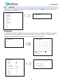
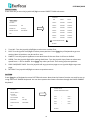
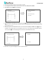
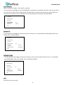
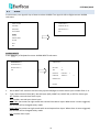
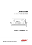
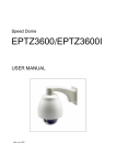
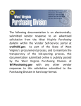
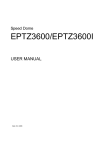
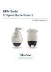
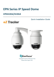
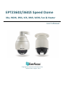
EPTZ3602/3602i Speed Dome 36x, 960H, IP66, ICR, DNR, WDR, Fan & Heater User’s Manual Copyright © EverFocus Electronics Corp, Release Date: August, 2014 Copyright 1995 - 2014 EverFocus Electronics Corp. All rights reserved. No part of the contents of this manual may be reproduced or transmitted in any form or by any means without written permission of the EverFocus Electronics Corporation. EverFocus 12F, No.79, Sec. 1, Shin-Tai Wu Road, Hsi-Chih, Taipei, Taiwan TEL: +886 2 2698 2334 FAX: +886 2 2698 2380 www.everfocus.com.tw August, 2014 About this document All the safety and operating instructions should be read and followed before the unit is operated. This manual should be retained for future reference. The information in this manual was current when published. The manufacturer reserves the right to revise and improve its products. All specifications are therefore subject to change without notice. Regulatory Notices FCC Notice "Declaration of Conformity Information" This equipment has been tested and found to comply with the limits for a Class A digital device, pursuant to part 15 of the FCC Rules. These limits are designed to provide reasonable protection against harmful interference in a residential installation. This equipment generates, uses and can radiate radio frequency energy and, if not installed and used in accordance with the instructions, may cause harmful interference to radio communications. However, there is no guarantee that interference will not occur in a particular installation. If this equipment does cause harmful interference to radio or television reception, which can be determined by turning the equipment off and on, the user is encouraged to try to correct the interference by one or more of the following measures: - Reorient or relocate the receiving antenna. - Increase the separation between the equipment and receiver. - Connect the equipment into an outlet on a circuit different from that to which the receiver is connected. - Consult the dealer or an experienced radio/TV technician for help. Warning: Changes or modifications made to this equipment, not expressly approved by EverFocus or parties authorized by EverFocus could void the user's authority to operate the equipment. This device complies with part 15 of the FCC Rules. Operation is subject to the following two conditions: (1) This device may not cause harmful interference, and (2) This device must accept any interference received, including interference that may cause undesired operation. EverFocus Electronics Corp. 12F, No. 79, Sec. 1, Shin-Tai Wu Rd., Hsi-Chi, Taipei Hsien, Taiwan, R.O.C. EPTZ cameras comply with CE and FCC. i Precautions 1. Do not install the camera near electric or magnetic fields. Install the camera away from TV/radio transmitters, magnets, electric motors, transformers and audio speakers since the electromagnetic fields generated from these devices may distort the video image or otherwise interfere with camera operation. 2. Never disassemble the camera beyond the recommendations in this manual nor introduce materials other than those recommended herein. Improper disassembly or introduction of corrosive materials may result in equipment failure or other damage. 3. Try to avoid facing the camera toward the sun. In some circumstances, direct sunlight may cause permanent damage to the sensor and/or internal circuits, as well as creating unbalanced illumination beyond the capability of the camera to compensate. 4. Keep the power cord away from water and other liquids and never touch the power cord with wet hands. Touching a wet power cord with your hands or touching the power cord with wet hands may result in electric shock. 5. Never install the camera in areas exposed to oil, gas or solvents. Oil, gas or solvents may result in equipment failure, electric shock or, in extreme cases, fire. 6. Cleaning For cameras with interchangeable lenses, do not touch the surface of the sensor directly with the hands. Use lens tissue or a cotton tipped applicator and ethanol to clean the sensor and the camera lens. Use a damp soft cloth to remove any dirt from the camera body. Please do not use complex solvents, corrosive or abrasive agents for cleaning of any part of the camera. 7. Do not operate the camera beyond the specified temperature, humidity or power source ratings. Use the outdoor camera at temperatures within -40°C ~ +50°C ≦ 95% / -40°F ~ +122°F ≦ 95% and the indoor camera at temperatures within -10°C ~ +50°C ≦ 85% / 14°F ~ +122°F ≦ 85%; this device is not rated as submersible. The input power source is 24 VAC~. Be sure to connect the proper + / - polarity and voltage, as incorrect polarity or too high a voltage will likely cause the camera to fail, and such damage is not covered by the warranty. The use of properly fused or Class 2 power limited type supplies is highly recommended. 8. Mounting Use care in selecting a solid mounting surface which will support the weight of the camera plus any wind, snow, ice or other loading, and securely attach the camera to the mounting surface using screws and anchors which will properly support the camera. If necessary (e.g. when mounting to drop ceilings) use a safety wire to provide additional support for the camera. ii Contents 1. Introduction..................................................................................................................................... 1 2. Features ............................................................................................................................................ 2 3. Installation ....................................................................................................................................... 2 3.1 3.2 3.3 3.4 3.5 4. Configuration in the OSD Menu .............................................................................................. 21 4.1 4.2 4.3 4.4 4.5 4.6 4.7 4.8 4.9 5. Packing List ............................................................................................................................... 2 Optional Accessories ................................................................................................................ 3 Cable Descriptions .................................................................................................................... 4 I/O Terminal Block .................................................................................................................... 5 Basic Installation for Outdoor Models ..................................................................................... 6 3.5.1 Installation Requirements ............................................................................................ 6 3.5.2 Important Note for Installation.................................................................................................... 7 3.5.2.1 Replacing the Desiccant Bags ...................................................................... 7 3.5.3 Initial Setup ........................................................................................................................................ 8 3.5.4 Wall-Mount Installation ............................................................................................................... 12 3.5.5 Ceiling Mount Installation ........................................................................................................... 15 3.5.6 EKB500 Connection ....................................................................................................................... 19 Video Settings......................................................................................................................... 21 Positions ................................................................................................................................. 24 OSD/Areas .............................................................................................................................. 26 Auto Modes ............................................................................................................................ 30 Alarm ...................................................................................................................................... 35 Private Zones (Optional) ........................................................................................................ 39 System .................................................................................................................................... 40 Info ......................................................................................................................................... 41 Exit .......................................................................................................................................... 41 Specifications ................................................................................................................................ 42 Appendix ................................................................................................................................................. 44 A.Setting-up and Operating EPTZ Camera Function Using EKB500 .................................................. 44 iii EPTZ3602/3602i 1. Introduction The EPTZ3602 series is a high-performance speed dome with a built-in 36x 960H optical zoom lens, supporting up to 700 TVL. The series comes in two types: outdoor (EPTZ3602) and indoor (EPTZ3602i). Equipped with a weather-resistant (IP66) housing, the outdoor models meet a wide variety of needs for outdoor surveillance. EverFocus speed dome provides variable pan/tilt speeds ranging from 360° per second to 0.01° per second with 0.1° position accuracy for fast and accurate monitoring. A maximum of 192 preset points can be configured for precise location of target areas. Features like 360° endless rotation, 16 tour sequences, 4 patterns are all provided. The speed dome also features IR Cut Filter, which can be removed or attached manually or automatically switched based on the detected light levels. 1 1 2 2 3 3 Outdoor (EPTZ3602) Indoor (EPTZ3602i) Item Name No. Item Name No. Item Name No. Item Name 1 2 3 Top Housing Outer Housing 1 Camera Main Body EPTZ3602/3602i 2. Features Built-in 36X 960H Optical Zoom Lens True Day and Night function (IR Cut Filter Removable) Digital Slow Shutter Built-in Dynamic Noise Reduction (DNR) Privacy Zone Masking (optional) Auto Detection of Protocols Tilt rotation range -90° 192 preset positions are available 16 cruise tours can be set, and each tour contains up to 16 positions 4 Alarm Inputs & 2 Alarm Outputs Running to positon speed, 0.01°/s to 360°/s RS-485 Communication IP 66 (for EPTZ3602) 3. Installation 3.1 Packing List There are 3 boxes that are camera main body with a camera module, top housing with a base board & pin connector and outer housing with bubble, plus one tool packet in the package. The detail accessories are listed below: Standard 1. Camera Main Body x 1 2. Top Housing x1 3. Outer Housing with Bubble x1 4. Tool Packet Hexagon Wrench x1 Glove x 1 Pair RS-485 Terminal Block Desiccant Packs x 3 Note: 1. Equipment configurations and supplied accessories vary by country. Please consult your local EverFocus office or agents for more information. Please also keep the shipping carton for possible future use. 2. Contact the shipper if any items appear to have been damaged in the shipping process. 2 EPTZ3602/3602i 3.2 Optional Accessories • EPTZ- PBOX (External power connection box) • Corner mount adapter (Used for fixing a wall-mount bracket to a 90° wall corner, indoors or outdoors.) • Pole mount adapter (Used for installing a wall-mount bracket to a pole, indoors or outdoors.) • Indoor ceiling pendant mount bracket (Used for installing a speed dome against a ceiling.) • Outdoor sunshield • Indoor recessed mount bracket • Wall mount bracket • Indoor concrete ceiling mount adapter (Used for attaching a speed dome to a concrete ceiling.) • EKB500 (RS-485 Keyboard) • EKB200 (USB controller keyboard) 3 EPTZ3602/3602i 3.3 Cable Descriptions Yellow RS485+ Orange RS485VIDEO 24VAC Power Cable An adapter with 24 VAC / 3.5A output provides the power to the EPTZ3602/EPTZ3602i. An extension power line may be needed. Note: Different regions may use different ranges for AC voltage. Be sure to check the voltage range in your area before installing. Video Cable A BNC cable is used for connecting an EPTZ3602/EPTZ3602i to a DVR or a monitor. An amplifier may be needed depending on the distance. RS-485 Cable The yellow wire carries RS-485+, and the orange wire carries RS-485-. Connect these wires to the EKB500 or other control device in order to control the PTZ camera. 4 EPTZ3602/3602i 3.4 I/O Terminal Block The base board that is inside the top housing connects to power cable, video cable, control cable, alarm cable and fan. The housing must be removed in order to properly connect the cables. The connectors of cable names are marked on the board in white text. There are 4 alarm inputs and 2 alarm outputs available, represented by Pin 1~12. Pin 13 and 14 are video pins for connecting to video cable. Pin15~16 are RS-485 pin for connecting to keyboard. Pin 17 and 18 are power pin for connecting to 24 VAC power. 1-12 Alarm 13-14 15-16 17-18 Video RS485 24VAC EPTZ3602/3602i Base Board Pin 1 2 3 4 5 6 7 8 9 Function ALM_NO_B (Alarm Output Normal Open B) ALM_COM_B (Alarm Output Common B) ALM_NC_B (Alarm Output Normal Close B) ALM_NO_A (Alarm Output Normal Open A) ALM_COM_A (Alarm Output Common A) ALM_NC_A (Alarm Output Normal Close A) ALMIN1 (Alarm Input 1) GND (Ground) ALMIN2 (Alarm Input 2) 5 Pin 10 11 12 13 14 15 16 17 18 Function ALMIN3 (Alarm Input 3) GND (Ground) ALMIN4 (Alarm Input 4) VIDEO+ VIDEORS485RS485+ AC24A+ AC24B- EPTZ3602/3602i 3.5 Basic Installation for Outdoor Models There are two ways to install the outdoor models of EPTZ series Speed Dome: Wall Mount and Ceiling Mount. 3.5.1 Installation Requirements The installation should be handled by a qualified service agent and should be complied with all local regulations. Service personnel should check potential problem such as surfaces strength, surface materials, falling objects, outer breaches, building vibration and other similar conditions. Check for all necessary materials, and ensure that the selected installation location is suitable for the camera. Installations on a wall, pole, or ceiling must be able to support at least five times the weight of the full camera assembly (about 16kg). Bracket Bracket base Top housing Main body 6 EPTZ3602/3602i 3.5.2 Important Note for Installation Before installing, replace the 3 desiccant bags inside the top housing. The desiccant bag loses its effectiveness after you open the camera. To keep the camera’s interior dry, it is highly recommended to replace the desiccant bags every time when you open the camera. 3.5.2.1 Replacing the Desiccant Bags 1. On the Top Housing, slightly press the black plastic socket backward and lift up the base board. 2. 3. Remove the desiccant bags from the top housing. Stick the supplied 3 new desiccant bags inside the top housing. Note: Ensure Not to place the desiccant bags under the position of the fan. 4. Insert the base board into the black plastic socket. The base board should click firmly into position. Make sure the pin connector on the base board is lined up with the pin connector on the main body when you press the two together. 7 EPTZ3602/3602i 3.5.3 Initial Setup To allow the control device, such as a keyboard, to recognize and then control multiple cameras, you need to set up the ID address for the cameras using the DIP switch on the Camera Main Body. You can also set up the Protocol and Baud Rate for the cameras. Note: Please ensure to turn off the power when setting up the DIP Switch. The new values will only take effect after restarting the camera. Camera Main Body DIP Switch ID Address The ID address of the camera should be set to correspond properly with the control device, such as a keyboard. The eight switches on the right correspond with the binary code of the ID address, allowing up to 256 ID addresses (0 ~ 255) to be set up. Please refer to the sticker on the camera main body or the following diagram for setting up the ID address. The default ID address is 1. DIP Switch Sticker on the Camera Main Body 8 EPTZ3602/3602i Switch Address ON 1 2 3 4 5 6 7 8 ON 1 2 3 4 5 6 7 8 2 3 4 5 6 7 8 2 3 4 5 6 7 8 ON 1 ON 1 ON 1 2 3 4 5 6 7 8 ON 1 2 3 4 5 6 7 8 ON 1 2 3 4 5 6 7 8 ON 1 2 3 4 5 6 7 8 ON 1 2 3 4 5 6 7 8 2 3 4 5 6 7 8 2 3 4 5 6 7 8 2 3 4 5 6 7 8 ON 1 ON 1 ON 1 ON 1 2 3 4 5 6 7 8 ON 1 2 3 4 5 6 7 8 ON 1 2 3 4 5 6 7 8 ON 1 2 3 4 5 6 7 8 ON 1 2 3 4 5 6 7 8 2 3 4 5 6 7 8 2 3 4 5 6 7 8 2 3 4 5 6 7 8 ON 1 ON 1 ON 1 ON 1 2 3 4 5 6 7 8 ON 1 2 3 4 5 6 7 8 ON 1 2 3 4 5 6 7 8 ON 1 2 3 4 5 6 7 8 ON 1 2 3 4 5 6 7 8 2 3 4 5 6 7 8 2 3 4 5 6 7 8 ON 1 ON 1 ON 1 2 3 4 5 6 7 8 ON 1 2 3 4 5 6 7 8 ON 1 2 3 4 5 6 7 8 ON 1 2 3 4 5 6 7 8 ON 1 2 3 4 5 6 7 8 Switch 0 ON 1 ON 2 ON 3 ON 4 ON 5 ON 6 ON 7 ON 8 ON 9 ON 10 ON 11 ON 12 ON 13 ON 14 ON 15 ON 16 ON 17 ON 18 ON 19 ON 20 ON 21 ON 22 ON 23 ON 24 ON 25 ON 26 ON 27 ON 28 ON 29 ON 30 ON 31 ON 1 1 1 1 1 1 1 1 1 1 1 1 1 1 1 1 1 1 1 1 1 1 1 1 1 1 1 1 1 1 1 1 2 3 4 5 6 Address 7 8 2 3 4 5 6 7 8 2 3 4 5 6 7 8 2 3 4 5 6 7 8 2 2 2 2 3 3 3 3 4 4 4 4 5 5 5 5 6 6 6 6 7 7 7 7 8 8 8 8 2 3 4 5 6 7 8 2 3 4 5 6 7 8 2 3 4 5 6 7 8 2 3 4 5 6 7 8 2 2 2 2 3 3 3 3 4 4 4 4 5 5 5 5 6 6 6 6 7 7 7 7 8 8 8 8 2 3 4 5 6 7 8 2 3 4 5 6 7 8 2 3 4 5 6 7 8 2 3 4 5 6 7 8 2 2 2 2 3 3 3 3 4 4 4 4 5 5 5 5 6 6 6 6 7 7 7 7 8 8 8 8 2 3 4 5 6 7 8 2 3 4 5 6 7 8 2 3 4 5 6 7 8 2 2 2 2 2 3 3 3 3 3 4 4 4 4 4 5 5 5 5 5 6 6 6 6 6 7 7 7 7 7 8 8 8 8 8 Switch 32 ON 33 ON 34 ON 35 ON 36 ON 37 ON 38 ON 39 ON 40 ON 41 ON 42 ON 43 ON 44 ON 45 ON 46 ON 47 ON 48 ON 49 ON 50 ON 51 ON 52 ON 53 ON 54 ON 55 ON 56 ON 57 ON 58 ON 59 ON 60 ON 61 ON 62 ON 63 ON 1 1 1 1 1 1 1 1 1 1 1 1 1 1 1 1 1 1 1 1 1 1 1 1 1 1 1 1 1 1 1 1 9 2 3 4 5 6 Address 7 8 2 3 4 5 6 7 8 2 3 4 5 6 7 8 2 3 4 5 6 7 8 2 2 2 2 3 3 3 3 4 4 4 4 5 5 5 5 6 6 6 6 7 7 7 7 8 8 8 8 2 3 4 5 6 7 8 2 3 4 5 6 7 8 2 3 4 5 6 7 8 2 3 4 5 6 7 8 2 2 2 2 3 3 3 3 4 4 4 4 5 5 5 5 6 6 6 6 7 7 7 7 8 8 8 8 2 3 4 5 6 7 8 2 3 4 5 6 7 8 2 3 4 5 6 7 8 2 3 4 5 6 7 8 2 2 2 2 3 3 3 3 4 4 4 4 5 5 5 5 6 6 6 6 7 7 7 7 8 8 8 8 2 3 4 5 6 7 8 2 3 4 5 6 7 8 2 3 4 5 6 7 8 2 2 2 2 2 3 3 3 3 3 4 4 4 4 4 5 5 5 5 5 6 6 6 6 6 7 7 7 7 7 8 8 8 8 8 Switch 64 ON 65 ON 66 ON 67 ON 68 ON 69 ON 70 ON 71 ON 72 ON 73 ON 74 ON 75 ON 76 ON 77 ON 78 ON 79 ON 80 ON 81 ON 82 ON 83 ON 84 ON 85 ON 86 ON 87 ON 88 ON 89 ON 90 ON 91 ON 92 ON 93 ON 94 ON 95 ON 1 1 1 1 1 1 1 1 1 1 1 1 1 1 1 1 1 1 1 1 1 1 1 1 1 1 1 1 1 1 1 1 Address 2 3 4 5 6 7 8 2 3 4 5 6 7 8 2 3 4 5 6 7 8 2 3 4 5 6 7 8 2 3 4 5 6 7 8 2 3 4 5 6 7 8 2 3 4 5 6 7 8 2 3 4 5 6 7 8 2 3 4 5 6 7 8 2 3 4 5 6 7 8 2 3 4 5 6 7 8 2 3 4 5 6 7 8 2 3 4 5 6 7 8 2 3 4 5 6 7 8 2 3 4 5 6 7 8 2 3 4 5 6 7 8 2 3 4 5 6 7 8 2 3 4 5 6 7 8 2 3 4 5 6 7 8 2 3 4 5 6 7 8 2 3 4 5 6 7 8 2 3 4 5 6 7 8 2 3 4 5 6 7 8 2 3 4 5 6 7 8 2 3 4 5 6 7 8 2 3 4 5 6 7 8 2 3 4 5 6 7 8 2 3 4 5 6 7 8 2 3 4 5 6 7 8 2 3 4 5 6 7 8 2 3 4 5 6 7 8 2 3 4 5 6 7 8 96 97 98 99 100 101 102 103 104 105 106 107 108 109 110 111 112 113 114 115 116 117 118 119 120 121 122 123 124 125 126 127 EPTZ3602/3602i Switch Address ON 1 2 3 4 5 6 7 8 ON 1 2 3 4 5 6 7 8 ON 1 2 3 4 5 6 7 8 2 3 4 5 6 7 8 2 3 4 5 6 7 8 ON 1 ON 1 ON 1 2 3 4 5 6 7 8 ON 1 2 3 4 5 6 7 8 ON 1 2 3 4 5 6 7 8 ON 1 2 3 4 5 6 7 8 ON 1 2 3 4 5 6 7 8 2 3 4 5 6 7 8 2 3 4 5 6 7 8 ON 1 ON 1 ON 1 2 3 4 5 6 7 8 ON 1 2 3 4 5 6 7 8 ON 1 2 3 4 5 6 7 8 ON 1 2 3 4 5 6 7 8 ON 1 2 3 4 5 6 7 8 2 3 4 5 6 7 8 2 3 4 5 6 7 8 2 3 4 5 6 7 8 ON 1 ON 1 ON 1 ON 1 2 3 4 5 6 7 8 ON 1 2 3 4 5 6 7 8 ON 1 2 3 4 5 6 7 8 ON 1 2 3 4 5 6 7 8 ON 1 2 3 4 5 6 7 8 2 3 4 5 6 7 8 2 3 4 5 6 7 8 ON 1 ON 1 ON 1 2 3 4 5 6 7 8 ON 1 2 3 4 5 6 7 8 ON 1 2 3 4 5 6 7 8 ON 1 2 3 4 5 6 7 8 ON 1 2 3 4 5 6 7 8 Switch 128 ON 129 ON 130 ON 131 ON 132 ON 133 ON 134 ON 135 ON 136 ON 137 ON 138 ON 139 ON 140 ON 141 ON 142 ON 143 ON 144 ON 145 ON 146 ON 147 ON 148 ON 149 ON 150 ON 151 ON 152 ON 153 ON 154 ON 155 ON 156 ON 157 ON 158 ON 159 ON 1 1 1 1 1 1 1 1 1 1 1 1 1 1 1 1 1 1 1 1 1 1 1 1 1 1 1 1 1 1 1 1 2 3 4 5 6 Address 7 8 2 3 4 5 6 7 8 2 3 4 5 6 7 8 2 3 4 5 6 7 8 2 3 4 5 6 7 8 2 2 2 2 3 3 3 3 4 4 4 4 5 5 5 5 6 6 6 6 7 7 7 7 8 8 8 8 2 3 4 5 6 7 8 2 3 4 5 6 7 8 2 3 4 5 6 7 8 2 2 2 2 3 3 3 3 4 4 4 4 5 5 5 5 6 6 6 6 7 7 7 7 8 8 8 8 2 3 4 5 6 7 8 2 3 4 5 6 7 8 2 3 4 5 6 7 8 2 3 4 5 6 7 8 2 2 2 2 3 3 3 3 4 4 4 4 5 5 5 5 6 6 6 6 7 7 7 7 8 8 8 8 2 3 4 5 6 7 8 2 3 4 5 6 7 8 2 3 4 5 6 7 8 2 2 2 2 2 3 3 3 3 3 4 4 4 4 4 5 5 5 5 5 6 6 6 6 6 7 7 7 7 7 8 8 8 8 8 Switch 160 ON 161 ON 162 ON 163 ON 164 ON 165 ON 166 ON 167 ON 168 ON 169 ON 170 ON 171 ON 172 ON 173 ON 174 ON 175 ON 176 ON 177 ON 178 ON 179 ON 180 ON 181 ON 182 ON 183 ON 184 ON 185 ON 186 ON 187 ON 188 ON 189 ON 190 ON 191 ON 1 1 1 1 1 1 1 1 1 1 1 1 1 1 1 1 1 1 1 1 1 1 1 1 1 1 1 1 1 1 1 1 10 2 3 4 5 6 Address 7 8 2 3 4 5 6 7 8 2 3 4 5 6 7 8 2 3 4 5 6 7 8 2 3 4 5 6 7 8 2 2 2 2 3 3 3 3 4 4 4 4 5 5 5 5 6 6 6 6 7 7 7 7 8 8 8 8 2 3 4 5 6 7 8 2 3 4 5 6 7 8 2 3 4 5 6 7 8 2 2 2 2 3 3 3 3 4 4 4 4 5 5 5 5 6 6 6 6 7 7 7 7 8 8 8 8 2 3 4 5 6 7 8 2 3 4 5 6 7 8 2 3 4 5 6 7 8 2 3 4 5 6 7 8 2 2 2 2 3 3 3 3 4 4 4 4 5 5 5 5 6 6 6 6 7 7 7 7 8 8 8 8 2 3 4 5 6 7 8 2 3 4 5 6 7 8 2 3 4 5 6 7 8 2 2 2 2 2 3 3 3 3 3 4 4 4 4 4 5 5 5 5 5 6 6 6 6 6 7 7 7 7 7 8 8 8 8 8 Switch 192 ON 193 ON 194 ON 195 ON 196 ON 197 ON 198 ON 199 ON 200 ON 201 ON 202 ON 203 ON 204 ON 205 ON 206 ON 207 ON 208 ON 209 ON 210 ON 211 ON 212 ON 213 ON 214 ON 215 ON 216 ON 217 ON 218 ON 219 ON 220 ON 221 ON 222 ON 223 ON 1 1 1 1 1 1 1 1 1 1 1 1 1 1 1 1 1 1 1 1 1 1 1 1 1 1 1 1 1 1 1 1 Address 2 3 4 5 6 7 8 2 3 4 5 6 7 8 2 3 4 5 6 7 8 2 3 4 5 6 7 8 2 3 4 5 6 7 8 2 3 4 5 6 7 8 2 3 4 5 6 7 8 2 3 4 5 6 7 8 2 3 4 5 6 7 8 2 3 4 5 6 7 8 2 3 4 5 6 7 8 2 3 4 5 6 7 8 2 3 4 5 6 7 8 2 3 4 5 6 7 8 2 3 4 5 6 7 8 2 3 4 5 6 7 8 2 3 4 5 6 7 8 2 3 4 5 6 7 8 2 3 4 5 6 7 8 2 3 4 5 6 7 8 2 3 4 5 6 7 8 2 3 4 5 6 7 8 2 3 4 5 6 7 8 2 3 4 5 6 7 8 2 3 4 5 6 7 8 2 3 4 5 6 7 8 2 3 4 5 6 7 8 2 3 4 5 6 7 8 2 3 4 5 6 7 8 2 3 4 5 6 7 8 2 3 4 5 6 7 8 2 3 4 5 6 7 8 224 225 226 227 228 229 230 231 232 233 234 235 236 237 238 239 240 241 242 243 244 245 246 247 248 249 250 251 252 253 254 255 EPTZ3602/3602i Protocol The first, second and the third switches on the left are used to set the communication protocol. Please refer to the sticker on the camera main body for setting up the protocol. The supported protocols are listed on the sticker. The default protocol is EVF. DIP Switch Sticker on the Camera Main Body Note: If you switch the three protocol switches to ON, the camera will enter a self-test mode. Baud Rate The fourth and fifth switches on the left are used to set the baud rate (transmission speed). Please refer to the sticker on the camera main body for setting up the baud rate. The default baud rate is 9600. DIP Switch Sticker on the Camera Main Body 11 EPTZ3602/3602i 3.5.4 Wall-Mount Installation 1. Drill 4 screw-depth holes for mounting the bracket base plate and then drill a through-wall hole for inserting the camera cables. You can optionally drill a second through-wall hole to separate cable feeding (see Step 3). 2. Attach the waterproof silicon pad to the bracket base plate for waterproofing. Waterproof Bracket base plate silicon pad 3. Feed the camera’s cables through the conduit in the wall mount bracket. Wall Mount Bracket 12 EPTZ3602/3602i 4. Connect the RS-485, video and power cables through the top hole of the base board. If necessary, connect the alarm cable as well using the bottom hole. 5. Screw the bracket base to the wall using the 4 screws. 6. Screw the wall mount bracket to the bracket base using the 4 long screws. 13 EPTZ3602/3602i 7. Put on the supplied gloves before pushing upward the main body into the top housing. Draw out the provided rope from the housing and hook it on the rope attachment hook of the main body. 8. Make sure the red triangle on the inside of the top housing lines up with the red triangle on the outside of the main body. Push the main body upward into the top housing until the orange catches on both sides click into position. Top Housing Main Body Note: 1. To release the main body, press the two orange release buttons on both sides. Make sure you are holding the main body firmly, otherwise it will fall down. 2. To protect the glass dome from getting dirty and scraped up, please put on the supplied gloves before installing. 14 EPTZ3602/3602i 9. Screw the housing cover to the top housing slowly by twisting it clockwise. Note: When you turn on the power, the camera will enter self-inspection mode and run a self-testing program. Once this is complete, you will be able to operate it via any IP network. 3.5.5 Ceiling Mount Installation It is required to use the optional Indoor Recessed Mount Bracket and Surface Ring to attach the camera to the ceiling for supporting the camera’s weight. Make sure the ceiling is strong enough to easily support the weight of the bracket and the camera. 1. Replace the desiccant bags inside the top housing. See 3.5.2.1 Replacing the Desiccant Bags. 2. Cut a hole on the ceiling using the supplied template. 15 EPTZ3602/3602i 3. Slightly turn the surface ring and remove it from the indoor recessed mount bracket. 4. Place and then screw the camera’s top housing on the top disk of the indoor recessed mount bracket by using the 3 short screws. Top Disk 5. Use a cable or other mechanism to hang the indoor recessed mount bracket on the ceiling. 16 EPTZ3602/3602i 6. Screw the 3 rotation clips of the indoor recessed mount bracket on the ceiling using a screwdriver. 7. Put on the supplied gloves before pushing upward the main body into the top housing. Draw out the provided rope from the housing and hook it on the rope attachment hook of the main body. 8. Make sure the red triangle on the inside of the top housing lines up with the red triangle on the outside of the main body. Push the main body upward into the top housing until the orange catches on both sides click into position. Top Housing Main Body Note: 1. To release the main body, press the two orange release buttons on both sides. Make sure you are holding the main body firmly, otherwise it will fall down. 2. To protect the glass dome from getting dirty and scraped up, please put on the supplied gloves before installing. 17 EPTZ3602/3602i 9. Screw the housing cover to the top housing slowly by twisting it clockwise. 10. Slide the surface ring to the fillister and slightly turn it until it is firmly fixed. Note: When you turn on the power, the camera will enter self-inspection mode and run a self-testing program. Once this is complete, you will be able to operate it via any IP network. 18 EPTZ3602/3602i 3.5.6 EKB500 Connection You can use EKB500 Keyboard to control the EPTZ cameras including the OSD menu setup or PTZ control. Follow the steps below to connect the EKB500 Keyboard to the EPTZ camera. EKB500 RJ-45 Cable White Blue Black Orange ( RS-485 - ) ( RS-485 + ) Yellow Black Red Green Connector Box RS-485 RS-485 + EPTZ Series 1 1. 2. 3. EPTZ Series 32 Connect the EPTZ cameras to the EKB500 using the RS-485 wires. Connect a monitor to the video cable of the EPTZ camera. Connect the power to the EKB500 (12 VDC) and EPTZ camera (24 VAC). 19 EPTZ3602/3602i After complete the above connection, you can start operating the EPTZ camera with EKB500 Keyboard: UP IRIS + Focus F. Zoom In - N. Out Zoom OUT Zoom IN LEFT RIGHT DOWN 1. 2. 3. 4. Move the Joystick up/down/left/right to shift the camera view in that direction. Twist the top of the Joystick to zoom in/out. Press the Zoom In/Out, Focus F/N or IRIS +/- to manually operate these functions. To enter the OSD menu of the EPTZ camera, press both of the Menu and CAM keys at the same time. For details on setting up the EPTZ functions using the EKB500 Keyboard, please refer to A. Setting-up and Operating EPTZ Camera Function Using EKB500 in Appendix. 20 EPTZ3602/3602i 4. Configuration in the OSD Menu You can use the keyboard to configure camera settings in the OSD menu. Note: The controls described in this chapter are based on using the EKB500 Keybaord. For EKB500 connection and operation, please refer to 3.5.5 EKB500 Connection. Press the Menu and CAM keys on the EKB500 Keyboard at the same time to enter the OSD root menu. Move the Joystick left/right to enter the sub-menu. VIDEO SETTINGS POSITIONS OSD/AREAS AUTO MODES ALARM SYSTEM (diagram 3.1) INFO EXIT 4.1 Video Settings In main menu, turn joystick Up / Down to select VIDEO SETTINGS. Turn joystick Left / Right to enter VIDEO SETTINGS sub-menu. VIDEO SETTINGS EXPOSURE<┘ POSITIONS FOCUS MODE ONE PUSH OSD/AREAS DIGITAL ZOOM OFF AUTO MODES WHITE BALANCE AUTO ALARM BACKLIGHT OFF PRIVATE ZONES DAY/NIGHT AUTO SYSTEM COLOR ON INFO NEGATIVE OFF EXIT DIG. NOISE REDUCE OFF WIDE DYNAMIC RANGE OFF DIS. MODE OFF EXIT 21 EPTZ3602/3602i EXPOSURE In Exposure menu, there is a sub-menu. Press Enter key or turn joystick Left / Right to enter Exposure sub-menu. EXPOSURE<┘ FOCUS MODE AUTO DIGITAL ZOOM OFF WHITE BALANCE AUTO BACKLIGHT OFF DAY/NIGHT AUTO COLOR ON NEGATIVE OFF DIG. NOISE REDUCE OFF WIDE DYNAMIC RANGE OFF DIS. MODE OFF EL. SHUTTER AUTO EXIT EXIT • EL.SHUTTER: Select electronic shutter mode from the options of the menu. There are AUTO, FLC, 1/250 , 1/500, 1/1000 , 1/2000, 1/4000, 1/10000, 1/30000, 1/60000 and 1/120000. • EXIT: Select Exit to save settings and exit from current page. FOCUS MODE In Focus mode, we define focus type from AUTO, Manual and One Push. • AUTO: Auto focus is enabled. It automatically adjusts the focus position to maximize the high frequency content of the picture in a center measurement area, taking into consideration the high luminance and strong contrast components. • • MANUAL: Enable the manual focus mode. ONE PUSH: Press the Enter key to fine-tune the camera focus. DIGITAL ZOOM Digital zoom enable or disable. • • ON: Enable the digital zoom. OFF: Disable the digital zoom. WHITE BALANCE White Balance has the following modes: • AUTO: this mode computed the white balance value output using color information from the entire screen. It outputs the proper value using the color temperature radiating from a black subject based on a range of value from 3000 to 7500K. • • • INDOOR: 3200 K Base mode. OUTDOOR: 5800 K Base mode. ONE PUSH: Select to force the camera to readjust the white balance. Note that the white balance will be readjusted every time you turn the joystick left/right to select ONE PUSH. • ATW: Select to apply the ATW mode. 22 EPTZ3602/3602i BACKLIGHT This is the function of Back Light Compensation. When the background of subject is too bright, or when the subject is too dark due to shooting in AE mode, back light compensation will make the subject appear clearer. • ON: Enable Back Light Compensation. • OFF: Disable Back Light Compensation. DAY/NIGHT In Day/Night, we define the ICR (IR Cut-Removable) mode settings. The camera has a built-in infrared (IR) cut-filter which can be disengaged from the image path for increased sensitivity in low light environments. Select from AUTO, DAY and NIGHT. • NIGHT: IR cut filter is always removed (ICR ON). • DAY: IR cut filter is always attached (ICR OFF). • AUTO: Auto Day/Night mode switch. The camera will automatically switch the settings needed for attaching or removing the IR cut filter. At a certain level of darkness, the IR cut-filter will be disabled and increase the infrared sensitivity (ICR ON). At a certain level of brightness, the IR cut-filter will reactivate automatically (ICR OFF). COLOR In Color, we define color of the image. Select from ON and OFF. • • ON: Color image. OFF: B/W image. NEGATIVE In Negative mode, it will switch ON/OFF the negative art image output. Select from ON and OFF. • • ON: Enable Negative function. OFF: Disable Negative function. DIG. NOISE REDUCE Switch ON/OFF to enable/disable the Digital Noise Reduction function. • • ON: Enable Digital Noise Reduction function. OFF: Disable Digital Noise Reduction function. WIDE DYNAMIC RANGE The WDR function provides clearer images when both of the very bright and dark areas simultaneously appear on the camera view. • • ON: Enable Wide Dynamic Range function. OFF: Disable Wide Dynamic Range function. DIS. MODE Switch ON/OFF to enable/disable the Digital Image Stabilizer function. • • ON: Enable Digital Image Stabilizer function. OFF: Disable Digital Image Stabilizer function. EXIT Select Exit to save settings and exit from current page. 23 EPTZ3602/3602i 4.2 Positions In main menu, turn joystick Up or Down to select POSITION option. Press Enter key or turn joystick Left / Right to enter POSITION sub-menu. VIDEO SETTINGS SET POSITIONS <┘ POSITIONS EXIT OSD/AREAS AUTO MODES ALARM PRIVATE ZONES SYSTEM INFO EXIT SET POSITIONS Tilt the joystick left/right to highlight a preset position and press Enter to select it. There are a total of 36 presets per page. Once the position is selected, a star sign (*) will appear next to the number. When finished, go to RETURN and tilt the joystick left/right to go to the Preset options. SET POSITIONS <┘ PRESET POSITION EXIT 1 2 3 4 5 6 7 8 9 10 11 12 13 14 15 16 17 18 19 20 21 22 23 24 25 26 27 28 29 30 31 32 33 34 35 36 PREV PAGE/NEXT PAGE RETURN PRESET NO. 1 POSITION SET <┘ SPEED 100 DWELL TIME (S) 4 FOCUS MODE MANUAL WHITE BALANCE AUTO TITLE 1 DEFAULT ON MOVE TO POSITION IRIS+: SAVE AND RETURN RETURN 24 EPTZ3602/3602i • POSITION: Select from SET and CLEAR. SET: Select SET and press Enter key of keyboard, you will be entered to a sub-menu. Turn the joystick to your desired position. Once the position is confirmed, press IRIS+ key of keyboard to save setting and return to previous menu. If position is set, there will be a star sign (*) beside position number. Clear: Select Clear and press Enter key of keyboard, and the POSITION will be cleared. You will automatically go back to the sub-menu of PRESET POSITION. PRESET POSITION 1 2 3 4 5 6 7 8 9 10 11 12 13 14 15 16 17 18 19 20 21 22 23 24 25 26 27 28 29 30 31 32 33 34 35 36 PREV PAGE/NEXT PAGE RETURN • SPEED: Select the speed for the preset position. The value is from 1 to 255 and 255 is the highest speed. • • • • DWELL TIME (S): Select the dwell time (in second) for the preset position from 1 to 99. FOCUS MODE: Select focus mode for the preset position from MANUAL, ONE PUSH and AUTO. WHITE BALANCE: Select the white balance for the preset position from Auto, Indoor and outdoor. TITLE: Enter title name for the preset position. Tilt the joystick up and down to scroll through the characters, then tilt left or right to move to the previous/next position. When finished, move the last digit and tilt the joystick right to return to previous screen. • DEFAULT: Select ON to set the preset position to default value. EXIT Select Exit to save settings and exit from current page. 25 EPTZ3602/3602i 4.3 OSD/Areas In main menu, turn joystick Up or Down to select OSD/AREAS. Turn joystick Left or Right to enter OSD/AREAS sub-menu. VIDEO SETTINGS POSITIONS CAM. TITLE OSD/AREAS AREAS <┘ AUTO MODES DIRECTIONS <┘ ALARM DISPLAY <┘ PRIVATE ZONES EXIT EPTZ3602_ _ SYSTEM INFO EXIT CAM. TITLE Enter the title name for the camera, up to a maximum of 10 characters. Tilt the joystick up and down to scroll through the characters, then tilt left or right to move to the previous/next position. When finished, move the last digit and tilt the joystick right to return to previous screen. AREAS Press Enter key of keyboard or turn joystick Left/Right to enter AREAS sub-menu. ZONE CAM. TITLE TITLE EPTZ3602_ _ 1. ---------------------------2. ---------------------------3. ---------------------------4. ---------------------------5. ---------------------------6. ---------------------------7. ---------------------------8. ---------------------------- AREAS <┘ DIRECTIONS <┘ DISPLAY <┘ EXIT RANGE CLR --------<┘ --------<┘ --------<┘ --------<┘ --------<┘ --------<┘ --------<┘ --------<┘ [<┘] [<┘] [<┘] [<┘] [<┘] [<┘] [<┘] [<┘] RETURN In zone menu, you can set a zone and name it, when the speed dome turns to the zone you set, it will display zone name on the screen (only if “OSD/AREAS->Display -> Zone” is set as “YES”). Tilt the joystick up and down to scroll through the characters, then tilt left or right to move to the previous/next position. When finished, tilt the joystick right to go to "Range" section, and press Enter key to enter Range sub-menu. Use the joystick to move speed dome to its left position. Press IRIS+ key to save left position setting and go to next step or press IRIS- to cancel. 26 EPTZ3602/3602i ZONE TITLE 1. ---------------------------2. ---------------------------3. ---------------------------4. ---------------------------5. ---------------------------6. ---------------------------7. ---------------------------8. ---------------------------- ZONE1 RANGE CLR --------<┘ --------<┘ --------<┘ --------<┘ --------<┘ --------<┘ --------<┘ --------<┘ [<┘] [<┘] [<┘] [<┘] [<┘] [<┘] [<┘] [<┘] MOVE TO LEFT POSITION IRIS+: SAVE AND NEXT STEP IRIS-: CANCEL RETURN Use the joystick to move speed dome to its right position. Press IRIS+ or IRIS- key to save and return. ZONE1 ZONE1 MOVE TO LEFT POSITION IRIS+: SAVE AND NEXT STEP IRIS-: CANCEL MOVE TO RIGHT POSITION IRIS+/IRIS-: SAVE AND RETURN Tilt the joystick right or left to highlight the current zone or tilt up/down to select a different zone. If you wish to clear the zone you have set, go to “CLR” and press Enter key. DIRECTIONS Press Enter key of keyboard or turn joystick Left/Right to enter DIRECTIONS sub-menu. CAM. TITLE DIRECTIONS NORTH EPTZ3602_ _ AREAS <┘ SET NORTH<┘ DIRECTIONS <┘ DEFAULT NORTH DISPLAY <┘ EXIT RETURN 27 [PUSH ENT] EPTZ3602/3602i 1. 2. 3. Press Enter key of keyboard or turn joystick Left/Right to enter Set North position menu. Move the joystick to North position. Press IRIS+ key of keyboard to save and return. DIRECTIONS NORTH SET NORTH <┘ DEFAULT NORTH [PUSH ENT] RETURN 4. 5. Go to “DEFAULT NORTH” and press Enter key to set the north position as default north position. Go to Return and turn joystick Left/Right to return to previous menu. DISPLAY Press Enter key of keyboard or turn joystick Left/Right to enter DISPLAY sub-menu (see diagram 3.14) SHOW OSD CAM. TITLE EPTZ3602_ _ AREAS <┘ DIRECTIONS <┘ DISPLAY <┘ EXIT ON DIRECTIONS NO CAMERA TITLE NO ZONES NO PRESET TITLE YES ZOOM NO FAN NO MOTION NO RETURN • SHOW OSD ON: Show OSD of Camera Title, Directions, Zones, Preset Title, Motion, Zoom and Fan. OFF: Do not show OSD. 2 SEC: Show OSD for 2 seconds. 5 SEC: Show OSD for 5 seconds. 10 SEC: Show OSD for 10 seconds. • DIRECTIONS YES: Show directions. NO: Do not show directions. • CAMERA TITLE YES: Show camera title. NO: Do not show camera title. 28 EPTZ3602/3602i • ZONES YES: Show zones. NO: Do not show zones. • PRESET TITLE YES: Show preset title. NO: Do not show preset title. • ZOOM YES: Show zoom multiple when zoom in or zoom out. NO: Do not show zoom multiple. • FAN YES: Show fan indication when fan is enabled. NO: Do not show fan indication. • MOTION YES: Show motion message when a motion occurs. NO: Do not show motion message when a motion occurs. • CAMERA STATUS YES: Shows camera status. NO: Do not show camera status. • RETURN Turn joystick Left/Right to return to previous menu. EXIT Select Exit to save settings and exit from current page. 29 EPTZ3602/3602i 4.4 Auto Modes In main menu, turn joystick Up/Down to select AUTO MODES. Turn joystick Left/Right to enter AUTO MODES sub-menu. VIDEO SETTINGS AUTOPAN <┘ POSITIONS PRESET TOURS <┘ OSD/AREAS PATTERN <┘ AUTO MODES AUTO RESUME OFF ALARM RESUME TO POS.1(H) PRIVATE ZONES POWER UP FUNC PREV MODE SYSTEM EXIT INFO EXIT AUTOPAN Press Enter key of keyboard or turn joystick Left/Right to enter AUTOPAN sub-menu. AUTOPAN <┘ AUTOPAN PRESET TOURS <┘ ENDLESS MODE ON PATTERN <┘ SPEED 32 AUTO RESUME OFF DWELL TIME L (S) 4 RESUME TO POS.1(H) DWELL TIME R (S) 4 POWER UP FUNC PREV MODE SET LEFT POS. <┘ [EMPTY] SET RIGHT POS. <┘ [EMPTY] DEFAULT ON EXIT RETURN • ENDLESS MODE ON: Enable endless mode. The speed dome will perform 360 degree endless auto-pan. OFF: Disable endless mode. The speed dome will perform auto-pan between position left and position right. • SPEED Select speed from 1~255 and 255 is the highest speed. • DWELL TIME L (S) Select dwell time of the left position from 1~99 seconds. • DWELL TIME R (S) Select dwell time of the right position from 1~99 seconds. 30 EPTZ3602/3602i • SET LEFT POS. Press Enter key or turn the joystick Left/Right to enter SET LEFT POS. menu. Turn the joystick to the position where you wish to set Left position. Press IRIS+ key of keyboard to save setting and return to previous menu. AUTOPAN ENDLESS MODE ON SPEED 32 DWELL TIME L (S) 4 DWELL TIME R (S) 4 SET LEFT POS. <┘ MOVE TO POSITION SET RIGHT POS. <┘ DEFAULT IRIS+: SAVE AND RETURN ON IRIS-: RETURN • SET RIGHT POS. Press Enter key or turn the joystick Left/Right to enter SET RIGHT POS. menu. Turn the joystick to the position where you wish to set RIGHT position. Press IRIS+ key of keyboard to save setting and return to previous menu. Note: When Left/Right Position are set, the speed dome will patrol between each position. AUTOPAN ENDLESS MODE ON SPEED 32 DWELL TIME L (S) 4 DWELL TIME R (S) 4 MOVE TO POSITION IRIS+: SAVE AND RETURN SET LEFT POS. <┘ SET RIGHT POS. <┘ DEFAULT ON IRIS-: RETURN • DEFAULT ON: All settings in AUTOPAN menu will be returned to default values. OFF: The setting in AUTOPAN menu is not default value. • RETURN Turn joystick Left/Right to return to previous menu. 31 EPTZ3602/3602i PRESET TOURS Press Enter key or turn the joystick Left/Right to enter PRESET TOURS sub-menu. TOUR NO. 1 AUTOPAN <┘ POS PRESET TOURS <┘ PATTERN <┘ DWELL SPEED 1 PRE1<┘ DEFAULT DEFAULT AUTO RESUME OFF 2 PRE2<┘ DEFAULT DEFAULT RESUME TO POS.1(H) 3 PRE3<┘ DEFAULT DEFAULT POWER UP FUNC PREV MODE 4 PRE4<┘ DEFAULT DEFAULT 5 PRE5<┘ DEFAULT DEFAULT 6 PRE6<┘ DEFAULT DEFAULT 7 PRE7<┘ DEFAULT DEFAULT EXIT PREV PAGE/NEXT PAGE RETURN 1. Tour NO.: Turn the joystick Left/Right to select tour number first. 2. POS: Turn the joystick Left/Right to select preset position. Press Enter key of keyboard to go next setting. Max. 16 positions can be set for a tour. DWELL: Turn the joystick Up/Down to set dwell time of the tour from 1~99 sec or default. SPEED: Turn the joystick Right after setting dwell time. Turn the joystick Up or Down to select tour speed from 1 ~255 or default. Press Enter key when you finish Tour setting of preset position. PREV PAGE/NEXT PAGE: Turn the joystick Left to go previous page or turn joystick Right to go next page. RETURN: Turn joystick Left/Right to return to previous menu. 3. 4. 5. 6. PATTERN Press Enter key of keyboard to enter PATTERN sub-menu. Note that the Pattern function can only be set up using EverFocus’ EKB500 keyboard. You can then operate the Pattern function through the DVR or EKB500 Keyboard. PATTERN SETUP AUTOPAN <┘ PATTERN DURATION ACTION PRESET TOURS <┘ PATTERN <┘ AUTO RESUME OFF RESUME TO POS.1(H) POWER UP FUNC PREV MODE EXIT PAT1 --- PLAY<┘ PAT2 --- PLAY<┘ PAT3 --- PLAY<┘ PAT4 --- PLAY<┘ RETURN 32 EPTZ3602/3602i 1. Turn the joystick Up or Down to select pattern number. 2. Turn the joystick Left or Right to select action mode, either PLAY, SET or CLEAR. 3. Select SET and press Enter key of keyboard. PATTERN SETUP PATTERN 1 RECORD MODE PATTERN DURATION ACTION 90s REMAIN PAT1 --- SET IRIS+: SAVE AND RETURN PAT2 --- PLAY IRIS-: CANCEL PAT3 --- PLAY PAT4 --- PLAY IRIS+: RETURN 4. Turn the joystick to record the tour you wish to set. Press IRIS+ when you finish setting pattern tour. Press IRIS- if you wish to cancel this action. At duration column of PATTERN SETUP menu, you will see the duration time of pattern you set. 5. When you return to PATTERN SETUP menu, turn the joystick Left/Right to PLAY. Press Enter key of keyboard. The camera starts to run the pattern tour you set. The camera keeps playing the pattern until you press IRIS- to cancel playing and it will return to PATTERN SETUP menu. PATTERN SETUP PATTERN 1 PLAY MODE PATTERN DURATION ACTION 90s REMAIN PAT1 --- PLAY PAT2 --- PLAY PAT3 --- PLAY PAT4 --- PLAY IRIS-: CANCEL IRIS+: RETURN 6. RETURN: Turn joystick Left/Right to return to previous menu. 33 1 EPTZ3602/3602i AUTO RESUME Return to previous mode, if no action for a period. Turn the joystick Left/Right to set AUTO RESUME. Auto Resume is selectable from OFF, After 30 sec, After 1 min, after 5 min, After 10 min, After 30 min and After 60 min. After this period of time, speed dome will resume to the mode you set in “RESUME TO”. By selecting OFF, this function will be disabled. AUTOPAN <┘ PRESET TOURS <┘ PATTERN <┘ AUTO RESUME OFF RESUME TO POS.1(H) EXIT RESUME TO Turn the joystick Left/Right to select the mode to resume to. It is selectable from PREV MODE, POS.1 (H), TOUR1, PAT.1 and AUTOPAN. AUTOPAN <┘ PRESET TOURS <┘ PATTERN <┘ AUTO RESUME OFF RESUME TO POS.1(H) POWER UP FUNC PREV MODE EXIT POWER UP FUNC Turn the joystick Left or Right to select the mode to return to when power failure occurs. It is selectable from PREV MODE, POS.1 (H), TOUR1, PAT.1, AUTOPAN and OFF. AUTOPAN <┘ PRESET TOURS <┘ PATTERN <┘ AUTO RESUME OFF RESUME TO POS.1(H) POWER UP FUNC PREV MODE EXIT EXIT Exit from the current menu. 34 EPTZ3602/3602i 4.5 Alarm In main menu, turn joystick Up or Down to select ALARM. Turn joystick Left or Right to enter ALARM sub-menu. VIDEO SETTINGS ALARM INPUTS <┘ POSITIONS ALARM OUTPUTS <┘ OSD/AREAS MOTION DETECT <┘ AUTO MODES EXIT ALARM PRIVATE ZONES SYSTEM INFO EXIT ALARM INPUTS Press Enter key of keyboard to enter ALARM INPUTS sub-menu. ALARM INPUTS <┘ ALARM INPUTS ALARM OUTPUTS <┘ MOTION DETECT <┘ INPUT NO. 1 EXIT TYPE NO REACTION POSITION<┘ 1 DURATION TIMEOUT<┘ 5 PRIORITY1234 RETURN 1. 2. Go to INPUT NO. selection and turn the joystick Left/Right to select alarm input number from 1 ~4. Type: Select Normal Close (NC), Normal Open (NO), NIGHT NC, NIGHT NO, or OFF for alarm type. NC: Enable a normal close alarm input. NO: Enable a normal open alarm input. NIGHT NC: Set camera at night mode with normal close alarm input. When there is event triggered, the camera will be changed to day mode. NIGHT NO: Set camera at night mode with normal open alarm input. When there is event triggered, the camera will be changed to day mode. OFF: Disable alarm input. 35 EPTZ3602/3602i 3. 4. 5. 6. REACTION: The action will be taken when alarm is triggered. OFF: No reaction will be taken when alarm is triggered. POSITION: When the alarm is triggered, speed dome will go to the preset position. Turn the joystick Left or Right to select on Position and press Enter key to select position number. Turn joystick Left/Right to make selection. It is selectable from 1~192. Press Enter key again to confirm selection. PATTERN: When the alarm is triggered, speed dome will run the pattern. Turn the joystick Left/Right to select on Pattern and press Enter key to select pattern number. Turn joystick Left/Right to make selection. It is selectable from1~4. Press Enter key again to confirm selection. TOUR: When the alarm is triggered, speed dome will run the tour. Turn the joystick Left or Right to select on Tour and press Enter key to select tour number. Turn joystick Left or Right to make selection. It is selectable from1~16. Press Enter key again to confirm selection. DURATION: Duration of alarm input. TIMEOUT: Turn the joystick Left or Right to select on TIMEOUT and press Enter key to select time-out. Time-out is selectable from 1~99. Press Enter key again to confirm selection. LATCHED: Turn the joystick Left or Right to select on LATCHED. The alarm output will not stop until there is any operation on keyboard. TRANSPARENT: Turn the joystick Left or Right to select on TRANSPARENT. The alarm output will not stop until the alarm is stopped. PRIORITY: Turn the joystick Left or Right to select alarm input priority, it is selectable from 1234/2341/3412/4123. RETURN: Turn joystick Left/Right to return to previous menu. ALARM OUTPUTS Press Enter key of keyboard to enter ALARM OUTPUTS sub-menu. ALARM INPUTS<┘ ALARM OUTPUT TRIGGER ALARM OUTPUTS <┘ MOTION DETECT <┘ OUTPUT NO 1 EXIT INPUT1 YES INPUT2 YES INPUT3 YES INPUT4 YES MOTION NO SYSTEM ERROR NO REMOTE NO RETURN 36 EPTZ3602/3602i 1. OUTPUT NUM: Select Output number from 1~2. 2. INPUT1: Select YES to enable Alarm input 1 for the alarm output selected. Select NO to disable Alarm input 1. 3. INPUT2: Select YES to enable Alarm input 2 for the alarm output selected. Select NO to disable Alarm input 2. 4. INPUT3: Select YES to enable Alarm input 3 for the alarm output selected. Select NO to disable Alarm input 3. 5. INPUT4: Select YES to enable Alarm input 4 for the alarm output selected. Select NO to disable Alarm input 4. 6. MOTION: Select YES to have alarm output triggered when a motion event is detected. Select NO to disable this function. 7. SYSTEM ERROR: Select YES to have alarm output triggered when system error occurs. Select NO to disable this function. 8. REMOTE: Select YES to have alarm output triggered when RS485 failure occurs. Select NO to disable this function. 9. RETURN: RETURN to the previous menu. MOTION DETECT Press Enter key of keyboard to enter MOTION DETECT sub-menu. You can set 4 motion areas. ALARM INPUTS <┘ MOTION DETECT 1 OFF ALARM OUTPUTS <┘ MOTION DETECT 2 OFF MOTION DETECT <┘ MOTION DETECT 3 OFF EXIT MOTION DETECT 4 OFF SENSITIVITY 240 INTERVAL TIME (S) 1 EXIT 1. Turn the joystick Left or Right to select ON for motion detection. A window as below pops up. MOTION DETECT INFO M1: 67 M2: 87 37 EPTZ3602/3602i 2. Press Enter key to enter Motion Detection Setting. Use the joystick to select motion area. Turn the joystick Up or Down to select directions, LEFT, RIGHT, UPPER or LOWER. Turn the joystick Left or Right to adjust the value of motion area. For Left & Right directions, it is selectable from 0 to 12. For Upper & Lower directions, it is selectable from 0 to 8. There is a color frame showing you the motion detection area you change. Motion 1 is represented by pink, Motion 2 by blue, Motion 3 by green and Motion 4 by yellow. Press IRIS+ key to save setting and return to previous menu. Press IRIS- to return to previous menu. MOTION DETECT SETTING 1 LEFT 0-----------12 RIGHT 0----------12 UPPER0-------8 LOWER 0-------8 RETURN 3. SENSITIVITY: select motion detection sensitivity level from 1~255. 4. INTERVAL TIME (S): select interval time in seconds from 1~255. Speed dome will stop detecting motion during this interval time. EXIT Exit from the current menu. 38 EPTZ3602/3602i 4.6 Private Zones (Optional) In main menu, turn joystick Up/Down to select PRIVATE ZONES masking. Turn joystick Left/Right to enter PRIVATE ZONE sub-menu. VIDEO SETTINGS POSITIONS OSD/AREAS AUTO MODES ALARM PRIVATE ZONES SYSTEM INFO PRIVATE ZONE 1 ON <┘ PRIVATE ZONE 1 OFF PRIVATE ZONE 1 OFF PRIVATE ZONE 1 OFF PRIVATE ZONE 1 OFF PRIVATE ZONE 1 OFF PRIVATE ZONE 1 OFF PRIVATE ZONE 1 OFF ZONE COLOR EXIT BLACK EXIT 1. ON: Turn joystick Left/Right to select ON/OFF. For private zone ON, press Enter key to enter private zone position. 2. Turn the joystick and move to position of private zone. Press IRIS+ or IRIS- key to set private zone size. PRIVATE ZONE 1 SIZE PRIVATE ZONE 1 POSITION SET ZONE SIZE MOVE TO POSITION IRIS-: JOYSTICK FOR PTZ IRIS+/IRIS-: JOYSTICK FOR SET SIZE IRIS+: SAVE AND RETURN 3. Select the area to be covered first. Turn joystick Left/Right to adjust width of the private zone area. Turn joystick Up or Down to adjust height of the private zone area. Press IRIS- key to set private zone position. Press IRIS+ to save and return to previous menu. PRIVATE ZONE 1 ON <┘ PRIVATE ZONE 1 OFF PRIVATE ZONE 1 OFF PRIVATE ZONE 1 OFF PRIVATE ZONE 1 OFF PRIVATE ZONE 1 OFF PRIVATE ZONE 1 OFF PRIVATE ZONE 1 OFF ZONE COLOR PRIVATE ZONE 1 SIZE SET ZONE SIZE IRIS-: JOYSTICK FOR PTZ IRIS+: SAVE AND RETURN BLACK EXIT 4. Zone color: select private zone area color. 5. Exit: exit from current menu. 39 EPTZ3602/3602i 4.7 System In main menu, turn joystick Up/Down to select SYSTEM. Turn joystick Left/Right to enter SYSTEM sub-menu. VIDEO SETTINGS AUTO INIT OFF POSITIONS LANGUAGE OSD/AREAS PASSWORD <┘ AUTO MODES LOAD DEFAULT [PUSH ENT] ALARM RESTART PRIVATE ZONES EXIT ENGLISH [PUSH ENT] SYSTEM INFO EXIT 1. AUTO INIT: Select auto initiation time from OFF, DAILY, WEEKLY. Speed dome will automatically initiate and return to the previous position by maintaining all the settings you have done. 2. LANGUAGE: Select language. The current version only supports English version. 3. PASSWORD: Press Enter key or turn joystick Left/Right to enter password sub-menu. AUTO INIT LANGUAGE OFF PASSWORD ENGLISH PASSWORD ACTIVE NO PASSWORD <┘ ENTER PASSWORD XXXX LOAD DEFAULT [PUSH ENT] VERIFY PASSWORD XXXX RESTART [PUSH ENT] EXIT SAVE AND RETURN RETURN -PASSWORD ACTIVE: Select YES to activate password mode. Select NO to disable password mode. -ENTER PASSWORD: Enter the password. -VERIFY PASSWORD: Enter the password again to confirm your input. Press IRIS+ key to save and return to previous menu. Press IRIS- key to cancel. -SAVE AND RETURN: Turn joystick Left/Right to save the changes and return to previous menu. -RETURN: Turn joystick Left/Right to return to previous menu without saving changes. 4. LOAD DEFAULT: Press Enter key to load default values, all values will return to factory default value. 5. Restart: Press Enter key to restart the speed dome. 6. EXIT: Exit from current menu. 40 EPTZ3602/3602i 4.8 Info In main menu, turn joystick Up or Down to select INFO. Turn joystick Left or Right to enter INFO sub-menu. EPTZ series VERSION: V2.2.15 PROTOCOL: AUTO BAUDRATE: 9600 RS-485-ID: 001 CAMERA: PRESET-CNT: 0000000000 X-CONT: 0000000001 Y-CONT: 0000000004 IRIS+: RETURN 1. 2. 3. 4. 5. VERSION: shows firmware version of this speed dome. PROTOCOL: shows protocol of this speed dome. BAUDRATE: shows baud rate of this speed dome. RS-485-ID: shows RS-485 ID of this speed dome. PRESET-CNT: Preset counter. This counter counts the preset movement, and 1 is counted when the speed dome runs to preset position. 6. X-CONT: X-axis counter. This counter counts the x axis movement, and 1 is counted when the speed dome pans 360°. 7. Y-CONT: Y-axis counter. This counter counts the y axis movement, and 1 is counted when the speed dome tilts 180°. 8. Press IRIS+ key to return to previous menu. 4.9 Exit Exit from the current menu. 41 EPTZ3602/3602i 5. Specifications Product Model EPTZ3602 (outdoor) EPTZ3602i (indoor) Pickup Device 1/4" Sony 960H Super HAD CCD II Video Format NTSC/PAL Scanning System 1020 x 508 (NTSC); 1020 x 596 (PAL) Horizontal Resolution Min. Illumination 700 TVL Normal: 0.1 Lux/F1.6; Night Mode: 0.05 Lux/F1.6 (ICR ON) S/N Ratio (AGC OFF) Electronic Shutter over 55dB 256x~ 1/60(1/50) ~ 1/120,000(s) (NTSC) Digital Slow Shutter Shutter Selection Lens Type Zoom Ratio 256x AUTO; A.FLK; Manual 256x~1/60 (1/50)~1/120,000 selectable 36x optical zoom, f=3.4 mm (wide) to 122.4mm (tele), F1.6 to F4.5 576x max (36x Optical and 16x Digital zoom) True Day & Night Yes, (Auto/Day/Night) Auto Gain Control Yes, (OFF/Low/Mid/High) Backlight Comp. Yes, (OFF/Low/Mid/High) Dynamic Noise Reduction Yes,(OFF/Low/Mid/High) White Balance Indoor/Outdoor/ATW/AWB Wide Dynamic Range Yes, (OFF/ON ) Motion Detection Yes, (OFF/ON ) Privacy Zone Masking Yes, (4-zone) Video Output 1Vp-p, 75Ω Sync. Mode Internal Focus Control Horizontal Rotation Speed Manual Pan/Tilt Speed One Push/Auto/Manual 0.01°/s-360°/s (1-255 grade shift gears) Pan: 0.01°~180°/s; Tilt: 0.01°~180°/s Position Accuracy ±0.1° Horizontal Rotation Range 360° unlimited rotation Tilt Rotation Range 90° pendulum motion Auto Speed Control Control speed auto-adjusted according to zoom length changing Auto Pan, 2 Points Scanning Auto Pan Speed Can set freely 1-255 grade available, 0.01º/s – 360º/s Dwell Time (2 points) 1-99 second available Preset Positions Running to Position Speed 192 positions 1-255 grade available, 0.01º/s - 360º/s Dwell Time at Preset 1-99 second available Tour 16 groups Tour Point per Group 16 preset positions 42 EPTZ3602/3602i Pattern 4 patterns with 90 sec long each Alarm 4 in 2 out with tour/position auto triggering Fan Auto starts Built-in Menu for Functions Yes Communication RS-485 Communication Speed 1200/2400/4800/9600bps Built-in Protocols AUTO; EVF; Pelco-P; Pelco-D/Plus-D; A-Type; Panasonic Address Editable Yes (through DIP switch) Speed Dome ID Address 0-255 Power Source 24 VAC Power Consumption Weather-Resistant Operating Temperature Dimensions (W x H) 30W Max. IP66-rated (only for EPTZ3602) -40°C~50°C ≤ 95% / -40°F~122°F ≤ 95%(EPTZ3602) -10°C~50°C ≤ 85% / 14°F~122°F ≤ 85%(EPTZ3602i) 180 x 280mm/7.1" x 11" (EPTZ3602) 159 x 230mm/6.3" x 9.1" (EPTZ3602i) Weight 3.0kg / 6.62lbs Certificates CE, FCC 43 EPTZ3602/3602i Appendix A. Setting-up and Operating EPTZ Camera Function Using EKB500 Manual Control Mode • Manual control: Shift Joystick Up/Down/Left/Right, and turn it Clockwise/Counterclockwise to control speed dome. Use the control keys which are Zoom, Focus and IRIS function keys on the keyboard to Zoom In/Out, focus N (near)/F (Far), or IRIS +/-. Note: Zoom In/Out control keys will be disabled when entering to OSD menu mode. • HOME Mode: The camera view will go back to the home position when there is no keyboard operation in a specific time. The home position and the specific time can be set by pressing Set + Home. If you set the time to 0 minute, then the camera will go back to home if there is no keyboard operation in 5 seconds. This is the minimum no action time for HOME mode. Note: If "HOME" function is enabled, dome will go to home immediately after powering on. Auto Pan Mode • Two point auto pan: Press A.Pan to enter the auto pan mode, and then the system will ask you to enter the auto pan speed (1~239). Press Enter to start auto pan. In order to set the two points, press Set + A.Pan, and then enter the dwell time (1~127 seconds) of each point. The EPTZ camera begins to pan from point A to point B clockwise. • 360° auto pan: Press Shift + A.Pan to enter the 360° auto pan. System will ask you to enter 360° auto pan speed (1~239). The camera will turn 360° automatically, but not tilt. Position Setting • Focus on a preset position: Press the number key, and then press Position to focus on the number of preset position; or you can press Position, then enter the preset position number, and then press Enter to focus on the number of preset position. • Preset a position: Shift the Joystick to the position you would like to preset, and then press Shift + Position. The system will ask you to enter the preset position number (1~192), and then press Enter to save the position. There are up to 192 positions can be preset. Three specific preset positions can be set as follows: 92 => Set Left Limit Stop (A position) 93 => Set Right Limit Stop (B position) 95 => Enter Menu mode (Use keyboard control keys to control OSD items; Focus F. to go downward, Focus N. to go upward. IRIS + go to previous setting and IRIS – to exit). 44 EPTZ3602/3602i You can directly go to the following specific preset positions: 33 => Rotation of 180 degree 34 => Go to Home position (if Home Position is set by EVF Keyboard) 90 => Run tour (one-way) 91 => Run Pattern 94 => Initial 96 => Stop Scan 97 => Start running tour 1 98 => Frame scan (60 degree / step) Default speed is 32. It can be changed by EVF Keyboard (Shift + A.Pan setting speed. Dwell time: default is 2 sec; It can be changed by EVF Keyboard Set + A.Pan setting dwell time of A pos or B pos. 99 => Auto scan (360 degree) Default speed is 32. It can be changed by EVF Keyboard (Shift + A.Pan setting speed). We can even set camera’s ICR Day/Night function with RS-485 command via keyboard. How to do this? Press Position + 88 to link to Day mode or Position + 89 to link to Night mode, “ICR AUTO” message will be shown on the right-bottom part of the screen. If OSD Day/Night ICR mode is “AUTO”, it cannot be controlled by preset position setting. • Set the parameter of a preset position: Press Set + Position to set the parameter of a preset position. You can set the going-to speed (1~239), dwell time (1~239 seconds), and the title of the position. Shift the joystick Right/Left to change bits, and shift the Joystick Up/Down to change the alphanumeric characteristic. The available alphanumeric characteristics are 0~9, A~Z, &, ?, !, :, ‘, ., ,, /, -, and a space. • Delete a preset position: Press Clr + Position to delete a preset position. The system will ask you to enter the position number that you would like to delete, and then press Enter. Tour Mode In the tour mode, you can set a tour for viewing. There are 16 tours can be set, and 16 preset positions in a tour. • One-way tour Mode: Press Tour to enter the tour mode. The system will ask you to enter the tour number you would like to run, and starts the tour after pressing Enter. To preset a tour before running is necessary. Preset a one-way tour: Press Set + Tour to preset a one-way tour. The system will ask you to enter preset position numbers (The positions need to be preset). After finish entering all positions, press Stop to quit, and then press Enter to save the tour. • To-and-fro tour mode: Press Shift + Tour to run a to-and-fro tour. The system will ask you to enter the tour number you would like to run, and starts the tour after pressing Enter. To preset a tour before running it is necessary. 45 EPTZ3602/3602i Note 1: The difference between the One-way tour mode and To-and-fro tour mode is that the return modes are different. For example: There is a tour with 3 preset positions 1, 2 and 3. The camera runs 1→2→3→1→2→3 in the One-way tour mode, and 1→2→3→2→1 in the To-and-fro tour mode. Note 2: You could set a pattern tour. Press Set + Tour, and input 0, press Enter. Sway the joystick to record the entire tour. Press Stop to stop recording tour. To view this pattern tour, simply press Tour, and input tour number 0. Alarm Link to a Position/Tour EPTZ3602/EPTZ3602i have 4 alarm inputs that can be set to link to a position or a tour when an alarm is triggered. • Set an alarm link: Press F1 to set an alarm link. Enter the alarm number, and then press Enter. Switch the Joystick up/down to select a position or a tour, enter a position or tour number, and then press Enter to confirm the alarm link setting. If you set the position number to 99, the dome will do a 360 degree auto scan or AB two point pan if limit is ON. If you set the position number to 98, the dome will do a frame scan. • Delete an alarm link: Press Clr + F1 to delete a link of alarm to position/tour. Note 1: After alarm output signal is terminated, the speed dome will resume action or return to its original position. Note 2: After powering on the speed dome, it will detect alarm status automatically. Other Operations The 3602/EPTZ3602i can work with a DVR that has PTZ control functions, and a matching protocol. The available control functions depend on different DVRs. The 3602/EPTZ3602i can work with a keyboard that has PTZ control functions, and a matching protocol. The available control functions depend on different keyboards. 46 EverFocus Electronics Corp. EverFocus Taiwan: 12F, No.79, Sec. 1, Shin-Tai Wu Road, Hsi-Chih, Taipei, Taiwan TEL: +886 2 2698 2334 FAX: +886 2 2698 2380 www.everfocus.com.tw [email protected] EverFocus Europe - Germany: Albert-Einstein-Strasse 1, D-46446 Emmerich, Germany TEL: +49 2822 93940 FAX: +49 2822 939495 www.everfocus.de [email protected] EverFocus China - Beijing: Room 609, Technology Trade Building, Shangdi Information Industry Base, Haidian District, Beijing 100085, China TEL: +86 10 6297 3336~39 FAX: +86 10 6297 1423 www.everfocus.com.cn [email protected] EverFocus China - Shenzhen: 4F, No. 2, D4 Building, Wan Yelong Industrial Park, Tangtou Road, Shiyan, Baoan, Shenzhen, Guangdong 518101, China TEL: +86 755 2765 1313 FAX: +86 755 2765 0337 www.everfocus.com.cn [email protected] EverFocus USA - California: 1801 Highland Avenue, Unit A, Duarte, CA 91010, USA TEL: +1 626 844 8888 FAX: +1 626 844 8838 www.everfocus.com [email protected] EverFocus USA - New York: 415 Oser Avenue, Unit S, Hauppauge, NY 11788, USA TEL: +1 631 436 5070 FAX: +1 631 436 5027 www.everfocus.com [email protected] EverFocus Japan: 3F, Kuramochi, Building II 2-2-3 Koto-Bashi, Sumida-Ku, Tokyo, 130-0022, Japan TEL: +81-3-5625-8188 FAX: +81 3 5625 8189 www.everfocus.co.jp [email protected] EverFocus China - Shanghai: Room 403, Ruijin Business Center, No.96, Zhaojiabang Road, Luwan district, Shanghai 200020, China TEL: +86 21 6471 2229 / 6471 2291 FAX: +86 21 6471 0566 www.everfocus.com.cn [email protected] EverFocus India: Suite 803, Housefin Bhavan, C-21, Bandra Kurla Complex, Bandra (East), Mumbai 400051, India TEL: +91 22 6128 8700 FAX: +91 22 6128 8705 www.everfocus.in [email protected] Your EverFocus product is designed and manufactured with high quality materials and components which can be recycled and reused. This symbol means that electrical and electronic equipment, at their end-of-life, should be disposed of separately from your household waste. Please, dispose of this equipment at your local community waste collection/recycling centre. In the European Union there are separate collection systems for used electrical and electronic product. Please, help us to conserve the environment we live in! Ihr EverFocus Produkt wurde entwickelt und hergestellt mit qualitativ hochwertigen Materialien und Komponenten, die recycelt und wieder verwendet werden können. Dieses Symbol bedeutet, dass elektrische und elektronische Geräte am Ende ihrer Nutzungsdauer vom Hausmüll getrennt entsorgt werden sollen. Bitte entsorgen Sie dieses Gerät bei Ihrer örtlichen kommunalen Sammelstelle oder im Recycling Centre. Helfen Sie uns bitte, die Umwelt zu erhalten, in der wir leben! P/N: 4605PP4036B012C