1
{
STIHL MS 311, 391
Instruction Manual
English
© ANDREAS STIHL AG & Co. KG, 2010
0458-542-0121-B. M1-7.G10.FST.
0000001812_006_GB
Printed on chlorine-free paper
Printing inks contain vegetable oils, paper can be recycled.
Original Instruction Manual
Contents
Guide to Using this Manual
Safety Precautions and Working
Techniques
Cutting Attachment
Mounting the Bar and Chain
Tensioning the Chain
Checking Chain Tension
Fuel
Fueling
Chain Lubricant
Filling Chain Oil Tank
Checking Chain Lubrication
Chain Brake
Winter Operation
Starting / Stopping the Engine
Operating Instructions
Oil Quantity Control
Taking Care of the Guide Bar
Air Filter System
Cleaning the Air Filter
Adjusting the Carburetor
Spark Arresting Screen in Muffler
Spark Plug
Replacing the Starter Rope and
Rewind Spring
Storing the Machine
Checking and Replacing the Chain
Sprocket
Maintaining and Sharpening the
Saw Chain
Maintenance and Care
Minimize Wear and Avoid Damage
2
2
14
14
15
15
16
17
18
19
19
20
21
22
25
26
26
27
27
28
29
30
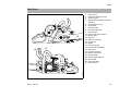
Main Parts
Specifications
Special Accessories
Ordering Spare Parts
Maintenance and Repairs
EC Declaration of Conformity
Quality Certification
41
42
43
44
44
44
45
Dear Customer,
Thank you for choosing a quality
engineered STIHL product.
This machine has been built using
modern production techniques and
comprehensive quality assurance.
Every effort has been made to ensure
your satisfaction and troublefree use
of the machine.
Please contact your dealer or our
sales company if you have any
queries concerning your machine.
Your
Hans Peter Stihl
31
33
33
34
38
40
{
MS 311, MS 391
1
English
Guide to Using this Manual
Pictograms
Handle heating
Pictograms that appear on the machine
are explained in this Instruction Manual.
Depending on the machine and
equipment version, the following
pictograms may appear on the machine.
Fuel tank; fuel mixture of
gasoline and engine oil
Tank for chain oil; chain
oil
Engage and release
chain brake
Coasting brake
Direction of chain travel
Ematic; chain oil flow
adjustment
Tension saw chain
Intake air baffle: winter
operation
2
Intake air baffle: summer
operation
Actuate decompression
valve
Actuate manual fuel
pump
Symbols in text
Warning where there is a risk of
an accident or personal injury or
serious damage to property.
Caution where there is a risk of
damaging the machine or its
individual components.
Engineering improvements
STIHL's philosophy is to continually
improve all of its products. For this
reason we may modify the design,
engineering and appearance of our
products periodically.
Therefore, some changes, modifications
and improvements may not be covered
in this manual.
Safety Precautions and
Working Techniques
Because a chain saw is a
high-speed wood-cutting
tool with very sharp cutters, some special safety
precautions must be
observed in addition to
those that generally apply
when working with an axe
or hand saw.
It is important you read
and understand the
instruction manual before
using your power tool for
the first time and keep
the manual in a safe
place for future reference. Non-observance of
the safety precautions
may result in serious or
even fatal injury.
Observe all applicable local safety
regulations, standards and ordinances.
If you have not used this type of power
tool before: Have your dealer or other
experienced user show you how to
operate your power tool or attend a
special course in its operation.
Minors should never be allowed to use a
power tool.
Keep bystanders, especially children,
and animals away from the work area.
When the power tool is not in use, shut it
off so that it does not endanger others.
Secure it against unauthorized use.
The user is responsible for avoiding
injury to third parties or damage to their
property.
MS 311, MS 391
English
Do not lend or rent your power tool
without the instruction manual. Be sure
that anyone using it understands the
information contained in this manual.
The use of noise emitting power tools
may be restricted to certain times by
national or local regulations.
To operate the power tool you must be
rested, in good physical condition and
mental health. If you have any condition
that might be aggravated by strenuous
work, check with your doctor before
operating a power tool.
Persons with pacemakers only: The
ignition system of your power tool
produces an electromagnetic field of a
very low intensity. This field may
interfere with some pacemakers. To
reduce health risks, STIHL recommends
that persons with pacemakers consult
their physician and the pacemaker
manufacturer before operating this tool.
Do not operate the power tool if you are
under the influence of any substance
(drugs, alcohol) which might impair
vision, dexterity or judgment.
To reduce the risk of accidents or
injury, put off the work in poor weather
conditions (rain, snow, ice, wind).
Use your saw for cutting wood or
wooden objects only.
Do not use your power tool for any other
purpose since this may result in
accidents.
Only use tools, guide bars, chains, chain
sprockets and accessories that are
explicitly approved for this power tool
model by STIHL or are technically
identical. If you have any questions in
this respect, consult a servicing dealer.
MS 311, MS 391
Use only high quality parts and
accessories in order to avoid the risk of
accidents and damage to the machine.
STIHL recommends the use of STIHL
original tools, guide bars, chains, chain
sprockets and accessories. They are
specifically designed to match your
model and meet your performance
requirements.
Never attempt to modify your power tool
in any way since this may increase the
risk of personal injury. STIHL excludes
all liability for personal injury and
damage to property caused while using
unauthorized attachments.
Do not use a pressure washer to clean
the unit. The solid jet of water may
damage parts of the unit.
Clothing and Equipment
Wear proper protective clothing and
equipment.
Clothing must be sturdy
but allow complete freedom of movement. Wear
snug-fitting clothing with
cut retardant inserts –
an overall and jacket
combination, do not wear
a work coat.
Avoid clothing that could get caught on
branches or brush or moving parts of the
machine. Do not wear a scarf, necktie or
jewelry. Tie up and confine long hair
(e.g. with a hair net, cap, hard hat, etc.).
Wear steel-toed safety
boots with cut retardant
inserts and non-slip
soles.
Wear a safety hard hat
where there is a danger
of head injuries from falling objects.
Wear safety glasses or a face shield
and hearing protection e.g. earplugs or
ear muffs.
Wear heavy-duty
gloves.
STIHL offers a comprehensive range of
personal protective clothing and
equipment.
Transporting the Chain Saw
Always engage the chain brake and fit
the chain guard (scabbard) before
carrying the saw short distances. Also
stop the engine before carrying the saw
longer distances (more than about 50
m).
Always carry the saw by the front handle
(handlebar) – with the hot muffler away
from your body – the guide bar must
point to the rear. To avoid serious burn
injuries, avoid touching hot parts of the
machine, especially the surface of the
muffler.
Transporting in a vehicle: Properly
secure your power tool to prevent
turnover, fuel spillage and damage.
3
English
Before starting
Gasoline is an
extremely flammable
fuel. Keep clear of naked
flames. Do not spill any
fuel – do not smoke.
Always shut off the engine before
refueling.
Do not fuel a hot engine – fuel may spill
and cause a fire.
Open the fuel cap carefully to allow any
pressure build-up in the tank to release
slowly and avoid fuel spillage.
Fuel your power tool only in wellventilated areas. If you spill fuel, wipe
the machine immediately – if fuel gets on
your clothing, change immediately.
Your power tool comes standard with
either a screw-type or bayonet-type fuel
cap.
After fueling, tighten
down the screw-type fuel
cap as securely as
possible.
Insert the fuel cap with
hinged grip (bayonet-type
cap) correctly in the
opening, turn it clockwise
as far as stop and fold the
grip down.
This reduces the risk of unit vibrations
causing the fuel cap to loosen or come
off and spill quantities of fuel.
4
Check that your power tool is properly
assembled and in good condition – refer
to appropriate chapters in the instruction
manual.
–
Check operation of chain brake,
front hand guard
–
Correctly mounted guide bar
–
Correctly tensioned chain
–
Smooth action of throttle trigger and
throttle trigger interlock – throttle
trigger must return automatically to
idle position.
–
Master Control lever / stop switch
must move easily to STOP or 0
–
Check that the spark plug boot is
secure – a loose boot may cause
arcing that could ignite combustible
fumes and cause a fire.
–
Never attempt to modify the controls
or the safety devices in any way.
–
Keep the handles dry and clean –
free from oil and pitch – for safe
control of the chain saw.
To reduce the risk of personal injury,
do not operate your saw if it is damaged
or not properly assembled.
Starting the engine
be clear of the ground and all other
obstructions because it may begin to run
when the engine starts.
Your chain saw is designed to be
operated by one person only. Do not
allow other persons in the work area –
even when starting.
To reduce risk of chain rotation and
personal injury, lock the chain with the
chain brake before starting.
Do not drop start your machine – the
correct starting procedure is described
in the instruction manual.
Do not attempt to start the saw when the
saw chain is in a cut.
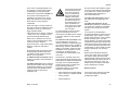
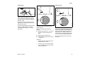
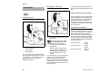
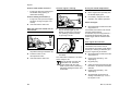
Holding and Controlling the Power
Tool
001BA087 LÄ
Fueling
Always hold your saw firmly with both
hands: Right hand on the rear handle,
even if you are left-handed. To ensure
safe control, wrap your fingers tightly
around the front and rear handles.
Start the engine at least 3 meters from
the fueling spot, outdoors only.
During Operation
Place the unit on firm ground in an open
area. Make sure you have good balance
and secure footing. Hold the unit
securely. The cutting attachment must
Make sure you always have good
balance and secure footing.
MS 311, MS 391
English
In the event of impending danger or in
an emergency, switch off the engine
immediately by moving the Master
Control lever / stop switch to STOP or 0.
Your power tool produces
toxic exhaust fumes as
soon as the engine is
running. These fumes
may be colorless and
odorless and contain
unburned hydrocarbons
and benzol. Never run
the engine indoors or in
poorly ventilated locations, even if your model
is equipped with a catalytic converter.
Your power tool is designed to be
operated by one person only. Do not
allow other persons in the work area.
Never leave a running machine
unattended.
When the engine is running: Note that
the chain continues to rotate for a short
period after you let go of the throttle
trigger (flywheel effect).
Take special care in slippery conditions
– damp, snow, ice, on slopes, uneven
ground and freshly debarked logs.
Watch out for obstacles such as tree
stumps, roots and ditches which could
cause you to trip or stumble.
Do not work alone – keep within calling
distance of others in case help is
needed.
Be particularly alert and cautious when
wearing hearing protection because
your ability to hear warnings (shouts,
alarms, etc.) is restricted.
To reduce the risk of accidents, take a
break in good time to avoid tiredness or
exhaustion.
To reduce risk of fire, keep hot exhaust
gases and hot muffler away from easily
combustible materials (e.g. wood chips,
bark, dry grass, fuel). Mufflers with a
catalytic converter can become
particularly hot.
MS 311, MS 391
To reduce the risk of serious or fatal
injury from breathing toxic fumes,
ensure proper ventilation when working
in trenches, hollows or other confined
locations.
To reduce the risk of accidents, stop
work immediately in the event of
nausea, headache, visual disturbances
(e.g. reduced field of vision), problems
with hearing, dizziness, deterioration in
ability to concentrate. Apart from other
possibilities, these symptoms may be
caused by an excessively high
concentration of exhaust gases in the
work area.
The dusts (e.g. sawdust), vapor and
smoke produced during operation may
be dangerous to health. If dust levels are
very high, wear a suitable respirator.
Check the saw chain at regular short
intervals during operation or
immediately if there is a noticeable
change in cutting behavior:
–
Shut off the engine and wait until the
chain comes to a complete stanstill.
–
Check condition
–
Check sharpness.
Do not touch the chain while the engine
is running. If the chain becomes jammed
by an obstruction, switch off the engine
immediately before attempting to
remove the obstruction.
To reduce the risk of injury, shut off
the engine before changing the saw
chain.
To reduce the risk of fire, do not
smoke while operating or standing near
your power tool. Note that combustible
fuel vapor may escape from the fuel
system.
If your power tool is subjected to
unusually high loads for which it was not
designed (e.g. heavy impact or a fall),
always check that it is in good condition
before continuing work – see also
"Before Starting". Check the fuel system
in particular for leaks and make sure the
safety devices are working properly. Do
not continue operating your power tool if
it is damaged. In case of doubt, have the
machine checked by your servicing
dealer.
Make sure the idle speed setting is
correct. The chain must not run when
the engine is idling with the throttle
trigger released. Check and correct the
idle speed setting at regular intervals. If
the saw chain still moves, have your
dealer check your machine and make
proper adjustments or repairs.
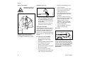
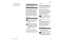
Reactive Forces
The most common reactive forces that
occur during cutting are: kickback,
pushback and pull-in.
5
English
001BA093 LÄ
Kickback can result in
serious or fatal injury.
–
–
when the upper quadrant of the bar
nose unintentionally contacts wood
or another solid object, e.g. when
another limb is touched accidentally
during limbing.
when the chain at the nose of the
guide bar is pinched in the cut.
001BA036 KN
Quickstop chain brake:
Kickback occurs when the saw is
suddenly thrown up and back in an
uncontrolled arc towards the operator.
This device reduces the risk of injury in
certain situations – it cannot prevent
kickback. If activated, the brake stops
the saw chain within a fraction of a
second – for a description of this device
refer to chapter on "Chain Brake" in this
manual.
Never cut several limbs at once.
–
Do not overreach.
–
Never cut above shoulder height.
–
Use extreme caution when reentering a previous cut.
–
Do not attempt plunge cuts if you
are not experience in this cutting
technique.
–
Be alert for shifting of the log or
other forces that may cause the cut
to close and pinch the chain.
–
Always cut with a correctly
sharpened, properly tensioned
chain – the depth gauge setting
must not be too large.
–
Use a low kickback chain and a
narrow radius guide bar.
Pull-in (A)
To reduce the risk of kickback
–
6
–
Work cautiously and avoid
situations which could cause
kickback.
–
Hold the saw firmly with both hands
and maintain a secure grip.
–
Always cut at full throttle.
–
Be aware of the location of the guide
bar nose at all times.
–
Do not cut with the bar nose.
–
Take special care with small, tough
limbs, they may catch the chain.
A
001BA037 KN
Kickback occurs, e.g.
Dangers of kickback
Pull-in occurs when the chain on the
bottom of the bar is suddenly pinched,
caught or encounters a foreign object in
the wood. The reaction of the chain pulls
the saw forward – always hold the
spiked bumper securely against the
tree or limb.
MS 311, MS 391
English
When felling in the vicinity of roads,
railways, power lines, etc., take extra
precautions. If necessary, inform the
police, utility company or railway
authority.
Pushback (B)
Make sure your saw does not touch any
foreign materials: Stones, nails, etc. may
be flung off, damage the saw chain or
cause the saw to kick back
unexpectedly.
001BA038 KN
Cutting
B
Pushback occurs when the chain on the
top of the bar is suddenly pinched,
caught or encounters a foreign object in
the wood. The reaction of the chain
drives the saw straight back toward the
operator. To avoid pushback.
–
Be alert to situations that may cause
the top of the guide bar to be
pinched
–
Do not twist the guide bar in the cut.
To reduce the risk of injury, take
special care when cutting shattered
wood because of the risk of injury from
slivers being caught and thrown in your
direction.
Do not operate your saw with the
starting throttle lock engaged. Engine
speed cannot be controlled with the
throttle trigger in this position.
Work calmly and carefully – in daylight
conditions and only when visibility is
good. Ensure you do not endanger
others – stay alert at all times.
Use the shortest possible guide bar: The
chain, guide bar and chain sprocket
must match each other and your saw.
with leaners
–
with trees that have fallen
unfavorably between other trees
and are under strain
–
when working in blowdown areas.
Do not work with the chainsaw in such
circumstances. Use block and tackle,
cable winch or tractor.
Pull out exposed and cleared logs.
Select clear area for cutting.
Deadwood (dry, decayed or rotted
wood) represents a considerable risk
that is difficult to assess. Identifying the
extent of the dangers is complicated, if
not impossible. Use aids such as a cable
winch or tractor in such cases.
MS 311, MS 391
001BA082 KN
–
001BA033 KN
Exercise extreme caution
Position the saw so that your body is
clear of the cutting attachment.
If on a slope, stand on the uphill side of
the log. Watch out for rolling logs.
Always pull the saw out of the cut with
the chain running.
When working at heights:
–
Always use a lift bucket
Use your chain saw for cutting only. It is
not designed for prying or shoveling
away limbs, roots or other objects.
–
Never work on a ladder or in a tree
–
Never work on an insecure support
Do not underbuck freely hanging limbs.
–
Do not work above shoulder height
–
Never operate your unit with one
hand
7
English
Begin cutting with the saw at full throttle
and engage the spiked bumper firmly in
the wood, and then continue cutting.
Never work without the spiked bumper
because the saw may pull you forwards
and off balance. Always hold the spiked
bumper securely against the tree or
limb.
Note when reaching the end of a cut that
the saw is no longer supported in the
kerf. You have to take the full weight of
the saw since it might otherwise go
out of control.
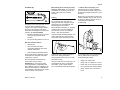
Felling
Do not attempt felling unless you have
been trained in the necessary
techniques. To reduce the risk of
accidents and injury, do not attempt
felling or limbing if you are not an
experienced chain saw user.
B
Escape paths
–
Establish paths of escape for
everyone concerned – opposite to
direction of fall at about 45°.
Pay special attention to the following
points:
–
Remove all obstacles from escape
paths.
–
The natural lean of the tree
–
–
Any unusually heavy limb structure,
damage
Place all tools and equipment a safe
distance away from the tree, but not
on the escape paths.
–
The wind direction and speed – do
not fell in high winds
–
Always keep to the side of the falling
tree and only walk away along the
preplanned escape path.
–
Sloping ground
–
–
Neighboring trees
On steep slopes, plan escape
routes parallel to the slope.
–
Snow load
–
–
Soundness of tree – take special
care if trunk is damaged or in case
of deadwood (dry, decayed or rotted
wood)
When walking away along the
escape path, watch out for falling
limbs and watch the top of the tree.
Determine direction of fall and
escape paths
Select gap in stand into which you want
the tree to fall.
B
Observe all country-specific regulations
on felling techniques.
Check that there are no other persons in
the felling area – other than helpers.
Make sure no-one is endangered by the
falling tree – the noise of your engine
may drown any warning calls.
Preparing work area at base of tree
–
First clear the tree base and work
area from interfering limbs and
brush to provide a secure footing.
–
Clean lower portion of tree base
(e.g. with an axe) – sand, stones
and other foreign objects will dull the
saw chain.
–
Remove large buttress roots: Make
the vertical cut first, then the
horizontal – but only if the wood is
sound
45°
A
1
Maintain a distance of at least 2 1/2 tree
lengths from the next felling site.
8
A
Direction of fall
001BA146 KN
001BA040 KN
1/ 2
21/2
B
1
001BA088 LÄ
45°
MS 311, MS 391
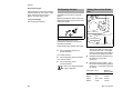
English
Sapwood cuts
Felling notch
001BA153 KN
C
When making the felling notch, make
use of the gunning sight on the shroud
and fan housing to check the planned
direction of fall.
C
The felling notch (C) determines the
direction of fall.
STIHL recommends the following
method:
N
Make the horizontal cut – check the
direction of fall with the gunning
sight.
N
Make angle cut at about 45°.
N
Check the felling notch and correct it
if necessary.
001BA150 KN
There are several approved methods for
making the felling notch – observe
country-specific regulations on felling
techniques.
001BA143 KN
Position your saw so that the gunning
sight points in exactly the direction you
want the tree to fall.
Sapwood cuts in long-fibered softwood
help prevent sapwood splintering when
the tree falls. Make cuts at both sides of
the trunk at same height as bottom of
felling notch to a depth of about 1/10 of
trunk diameter. On large diameter trees,
cut to no more than width of guide bar.
Do not make sapwood cuts if wood is
diseased.
Important:
MS 311, MS 391
–
Felling notch at a right angle to the
planned direction of fall.
–
As close to the ground as possible.
–
Cut to a depth of about 1/5 to 1/3 of
the trunk diameter.
9
English
Small diameter trees: Simple fan cut
Felling
E
D
E
Shout a warning before starting the
felling cut.
N
Make the felling cut (D) slightly
higher than bottom of the felling
notch.
–
Cut horizontally.
–
Leave approx. 1/10 of the tree
diameter uncut between the felling
cut and the felling notch. This is the
hinge.
The hinge (E) helps control the falling
tree.
–
Do not cut through the hinge – you
could lose control of the direction of
fall – this could result in an
accident.
–
Leave a broader hinge on rotten
trees.
001BA147 KN
001BA145 KN
001BA144 KN
D
N
Apply the spiked bumper behind the
hinge – pivot the saw around this
point - only as far as the hinge. The
spiked bumper rolls against the
trunk.
Shout a second warning immediately
before the tree falls.
Drive wedges into the felling cut in good
time. Use only wooden, aluminum or
plastic wedges. Never steel, which can
damage the chain and cause kickback.
10
MS 311, MS 391
English
Large diameter trees: Sectioning
method
2
4
001BA148 KN
1
If the diameter of the tree is greater than
the length of the guide bar, use the
sectioning method.
1.
1
First cut
Nose of guide bar should enter
wood just behind the hinge – hold
the saw horizontally and swing it as
far as possible, using the bumper
spike as a pivot – avoid
repositioning the saw more than
necessary.
2.
When repositioning the saw for the
next cut, keep the guide bar fully
engaged in the kerf to keep the
felling cut straight – apply the spiked
bumper again, and so on.
3.
Insert a wedge (3) in the cut.
4.
Last cut: Apply the spiked bumper
as for the simple fan cut – do not cut
through the hinge.
2
001BA179 KN
3
N
Use a low kickback chain and
exercise particular caution
1.
Begin cut by applying the lower
portion of the guide bar nose – do
not use upper portion because of –
risk of kickback. Cut until depth of
kerf is twice the width of the guide
bar.
2.
Swing saw slowly into plungecutting position – take care because
of the risk of kickback or
pushback.
3.
Make the plunge cut very carefully.
Danger of pushback.
Heartwood cut
Special cutting techniques
Plunge cuts and heartwood cuts require
special training and experience.
Plunge cutting
MS 311, MS 391
–
For felling leaners
–
For relieving cuts during bucking
–
For DIY projects
–
If tree diameter is more than twice
the length of the guide bar.
–
If a large portion of heartwood
remains uncut on large diameter
trees.
11
English
Make the plunge cut in the center of
the felling notch – there is a danger
of pushback at this point – then
swing the bar in the direction of the
arrow.
Limbing
Do not attempt limbing unless you have
been trained in the necessary
techniques. To reduce the risk of
accidents and injury, do not attempt
felling or limbing if you are not an
experienced chain saw user.
–
Use a low kickback chain.
–
Work with the saw supported
wherever possible.
–
Do not stand on the log while
limbing it.
–
Do not cut with the bar nose.
–
Watch for limbs which are under
tension.
–
Never cut several limbs at once.
12
–
Use a sturdy and stable support –
sawhorse.
–
Never hold the log with your leg or
foot.
–
Never allow another person to hold
the log or help in any other way.
Do not cut a lying log at a point
where it is touching the ground
because the saw chain will
otherwise be damaged.
Ripping cut
Lying or standing logs under tension
Always make cuts in the correct
sequence (first at the compression
side (1), then at the tension side (2), the
saw may otherwise pinch or kick back–
risk of injury.
1
2
2
1
N
Make relieving cut at the
compression side (1)
N
Make bucking cut at the tension
side (2)
001BA189 KN
N
On soft deciduous trees to relieve
tension in lying log and prevent
slivers in the center of the hinge
being torn out of the log.
Be wary of pushback when making
bucking cut from the bottom upwards
(underbuck).
When cutting small logs
001BA151 KN
–
On trees that are difficult to fell (oak,
beech), to prevent heartwood
splintering and maintain planned
direction of fall.
001BA152 KN
–
Cutting technique in which the bumper
spike is not used – risk of pull-in – start
the cut with the guide bar at the
shallowest possible angle – take extra
care since there is an increased danger
of kickback.
MS 311, MS 391
English
Vibrations
Prolonged use of the power tool may
result in vibration-induced circulation
problems in the hands (whitefinger
disease).
No general recommendation can be
given for the length of usage because it
depends on several factors.
The period of usage is prolonged by:
–
Hand protection (wearing warm
gloves)
–
Work breaks
The period of usage is shortened by:
–
Any personal tendency to suffer
from poor circulation (symptoms:
frequently cold fingers, tingling
sensations).
–
Low outside temperatures.
–
The force with which the handles
are held (a tight grip restricts
circulation).
Continual and regular users should
monitor closely the condition of their
hands and fingers. If any of the above
symptoms appear (e.g. tingling
sensation in fingers), seek medical
advice.
Maintenance and Repairs
Service the machine regularly. Do not
attempt any maintenance or repair work
not described in the instruction manual.
Have all other work performed by a
servicing dealer.
MS 311, MS 391
STIHL recommends that you have
servicing and repair work carried out
exclusively by an authorized STIHL
servicing dealer. STIHL dealers are
regularly given the opportunity to attend
training courses and are supplied with
the necessary technical information.
Only use high-quality replacement parts
in order to avoid the risk of accidents
and damage to the machine. If you have
any questions in this respect, consult a
servicing dealer.
To reduce the risk of fire and damage
to hearing, do not operate your
machine if the muffler is damaged or
missing. –
Do not touch a hot muffler since burn
injury will result.
Vibration behavior is influenced by the
condition of the AV elements – check the
AV elements at regular intervals.
Check the chain catcher and replace it
if damaged.
STIHL recommends the use of genuine
STIHL replacement parts. They are
specifically designed to match your
model and meet your performance
requirements.
Stopping the Engine
To reduce the risk of injury, always shut
off the engine before carrying out any
maintenance or repairs or cleaning the
machine. – Exception: Carburetor and
idle speed adjustments.
Do not turn the engine over on the
starter with the spark plug boot or spark
plug removed unless the slide control /
stop switch is on STOP or 0 since there
is otherwise a risk of fire from
uncontained sparking.
To reduce the risk of fire, do not service
or store your machine near open flames.
Check the fuel filler cap for leaks at
regular intervals.
Use only a spark plug of the type
approved by STIHL and make sure it is
in good condition – see "Specifications".
Inspect the ignition lead (insulation in
good condition, secure connection).
Check the condition of the muffler.
–
before checking chain tension.
–
before retensioning the chain.
–
before replacing the chain.
–
before rectifying problems.
Observe sharpening instructions –
keep the chain and guide bar in good
condition at all times for safe and correct
handling of the saw. The chain must be
properly sharpened, tensioned and well
lubricated.
Always change the chain, guide bar and
sprocket in good time.
Check condition of clutch drum
periodically.
Store fuel and chain lubricant in properly
labelled, safety-type canisters only.
When handling gasoline, avoid direct
contact with the skin and avoid inhaling
fuel vapour – health risk.
To reduce the risk of injury, shut off the
engine immediately if the chain brake
malfunctions – contact your servicing
dealer – do not use your power tool until
the problem has been rectified (see
"Chain Brake").
13
English
Cutting Attachment
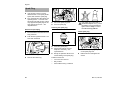
Disengaging the chain brake.
Mounting the Bar and
Chain
STIHL is the only manufacturer in the
industry to produce its own chain saws,
guide bars, saw chains and chain
sprockets.
Removing the chain sprocket cover
001BA186 KN
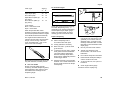
A cutting attachment consists of the saw
chain, guide bar and chain sprocket.
N
3
–
The pitch (t) of the saw chain (1),
chain sprocket and the nose
sprocket of the Rollomatic guide bar
must match.
–
The drive link gauge (2) of the saw
chain (1) must match the groove
width of the guide bar (3).
If non-matching components are used,
the cutting attachment may be damaged
beyond repair after a short period of
operation.
14
Pull the hand guarad towards the
front handle until there is an audible
click – the chain brake is
disengaged.
Fitting the chain
1
2
N
Turn the screw (1)
counterclockwise until the tensioner
slide (2) butts against the left end of
the housing slot.
143BA003 KN
a
t=a:2
Unscrew the nuts and take off the
chain sprocket cover.
001BA191 KN
2
N
001BA185 KN
1
143BA034 KN
The cutting attachment that comes
standard is designed to exactly match
the chain saw.
Wear work gloves to protect your
hands from the sharp cutters.
N
Fit the chain – start at the bar nose.
MS 311, MS 391
English
Tensioning the Chain
1
1
143BA007 KN
2 4
133BA024 KN
1
001BA187 KN
3
Checking Chain Tension
N
Fit the guide bar over the studs (1) –
the cutting edges on the top of the
bar must point to the right.
N
Engage the peg of the tensioner
slide in the locating hole (2) –- place
the chain over sprocket (3) at the
same time.
Retensioning during cutting work:
N
Shut off the engine.
N
Shut off the engine.
N
N
Loosen the nuts.
Wear work gloves to protect your
hands.
Turn the tensioning
screw (4)clockwise until there is
very little chain sag on the
underside of the bar – and the drive
link tangs are engaged in the bar
groove.
N
Hold the bar nose up.
N
N
Use a screwdriver to turn the
tensioning screw (1) clockwise until
the chain fits snugly against the
underside of the bar.
The chain must fit snugly against
the underside of the bar and it must
still be possible to pull the chain
along the bar by hand.
N
If necessary, retension the chain.
N
N
Refit the sprocket cover and screw
on the nuts only fingertight.
N
Go to chapter on "Tensioning the
Saw Chain"
N
While still holding the bar nose up,
tighten down the nuts firmly.
N
Go to "Checking Chain Tension".
A new chain has to be retensioned more
often than one that has been in use for
some time.
N
MS 311, MS 391
A new chain has to be retensioned more
often than one that has been in use for
some time.
N
Check chain tension frequently –
see chapter on "Operating
Instructions".
Check chain tension frequently –
see chapter on "Operating
Instructions".
15
English
Fuel
Your engine requires a mixture of
gasoline and engine oil.
For health reasons, avoid direct
skin contact with gasoline and
avoid inhaling gasoline vapor.
STIHL MotoMix
A few tankfuls of leaded gasoline
will greatly reduce the efficiency of
the catalytic converter.
Storing Fuel
Use only quality two-stroke engine oil.
We recommend STIHL two-stroke
engine oil since it is specially
formulated for use in STIHL engines
and guarantees a long engine life.
Store fuel only in approved safety-type
fuel canisters in a dry, cool and safe
location protected from light and the sun.
STIHL recommends the use of STIHL
MotoMix. This ready-to-use fuel mix
contains no benzol or lead, has a high
octane rating and ensures that you
always use the right mix ratio.
STIHL MotoMix is specially formulated
for use in STIHL engines and
guarantees a long engine life.
Use only STIHL 50:1 two-stroke
engine oil for the fuel mix in models with
a catalytic converter.
Mixing Fuel
Unsuitable fuels or lubricants or
mix ratios other than those
specified may result in serious
damage to the engine. Poor
quality gasoline or engine oil may
damage the engine, sealing rings,
hoses and the fuel tank.
Gasoline
Use only high-quality brand-name
gasoline with a minimum octane rating
of 90 – leaded or unleaded.
If your machine is equipped with a
catalytic converter, you must use
unleaded gasoline.
16
Use a canister approved for storing
fuel. Pour oil into canister first, then
add gasoline and mix thoroughly.
Engine Oil
If STIHL two-stroke engine oil is not
available, use only quality two-stroke oil
designed for use in air-cooled engines.
Do not use oils designed for watercooled engines or engines with a
separate lubricating system (e.g.
conventional four-stroke engines).
MotoMix is not available in all markets.
N
Mix Ratio
N
Examples
STIHL engine oil 50:1
Liters (ml)
0,02 (20)
0,10 (100)
0,20 (200)
0,30 (300)
0,40 (400)
0,50 (500)
Thoroughly shake the mixture in the
canister before fueling your
machine.
Pressure may build up in the
canister – open it carefully.
N
STIHL 50:1 two-stroke engine oil: 50
parts gasoline to 1 part oil
Gasoline
Liters
1
5
10
15
20
25
Fuel mix ages – only mix sufficient fuel
for a few weeks work. Do not store fuel
mix for longer than 3 months. Exposure
to light, the sun, low or high
temperatures can quickly make the fuel
mix unusable.
Clean the fuel tank and canister
from time to time.
Dispose of remaining fuel and cleaning
fluid properly in accordance with local
regulations and environmental
requirements.
Other brand-name two-stroke
engine oils: 25 parts gasoline to 1
part oil
MS 311, MS 391
English
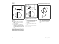
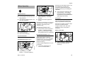
Closing
Fuel filler cap
N
001BA220 KN
001BA219 KN
Fueling
Turn the cap counterclockwise
(approx. 1/4 turn)
N
Before fueling, clean the cap and
the area around it to ensure that no
dirt falls into the fuel tank
Always position the machine so that
the cap is facing upwards
N
N
Push the cap down as far as it will
go
N
Hold the cap down and twist it
clockwise until it engages
N
Fold down the clip as far as it will go
Remove fuel filler cap
Refueling
Take care not to spill fuel while fueling
and do not overfill the tank.
Opening
Fit the cap – position marks on the
cap and the filling port must line up
STIHL recommends use of the STIHL
filling system for fuel (special
accessory).
Refueling
N
Swing the clip into an upright
position
MS 311, MS 391
001BA222 KN
001BA218 KN
N
001BA221 KN
N
N
001BA224 KN
001BA229 KN
Clip is in an upright position:
17
English
Checking the lock
N
Left:
Right:
Grip the cap – if the cap cannot be
moved or removed, then it is closed
properly
18
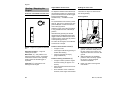
For automatic and reliable lubrication of
the chain and guide bar – use only an
environmentally compatible quality
chain and bar lubricant. Rapidly
biodegradable STIHL Bioplus is
recommended.
Biological chain oil must be
resistant to aging (e.g. STIHL
Bioplus) since it will otherwise
quickly turn to resin. This results
in hard deposits that are difficult to
remove, especially in the area of
the chain drive, clutch and chain.
It may even cause the oil pump to
seize.
N
Fit cap and twist it counterclockwise
until it engages in the seat of the
filling port
N
Continue to twist the cap
counterclockwise (approx. 1/4 turn)
– this will twist the base of the cap
into the correct position
N
Twist the cap clockwise and close it
– see the section "Closing" and
"Checking the lock"
If the cap can be moved or removed
The base of the cap is tilted in relation to
the upper part:
Base of cap tilted
Base of cap correctly
positioned
001BA226 KN
The lug on the clip must engage
entirely in the recess (arrow)
001BA225 KN
–
001BA227 KN
001BA223 KN
Chain Lubricant
The service life of the chain and guide
bar depends on the quality of the
lubricant. It is therefore essential to use
only a specially formulated chain
lubricant.
Do not use waste oil. Renewed
contact with waste oil can cause
skin cancer. Moreover, waste oil is
environmentally harmful.
Waste oil does not have the
necessary lubricating properties
and is unsuitable for chain
lubrication.
MS 311, MS 391
English
If the oil level in the tank does not go
down, the reason may be a fault in the oil
supply system: Check chain lubrication,
clean the oilways, contact your dealer
for assistance if necessary STIHL
recommends that you have servicing
and repair work carried out exclusively
by an authorized STIHL servicing
dealer.
Filling Chain Oil Tank
N
Thoroughly clean the oil filler cap
and the area around it to ensure that
no dirt falls into the tank.
N
Position the machine so that the
filler cap is facing up.
N
Open the filler cap.
Fill up with chain oil.
N
Refill the chain oil tank every time
you refuel.
Take care not to spill chain oil while
refilling and do not overfill the tank.
STIHL recommends you use the STIHL
filler nozzle for chain oil (special
accessory).
N
Close the filler cap.
143BA024 KN
001BA158 KN
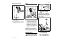
Preparations
Checking Chain
Lubrication
The saw chain must always throw off a
small amount of oil.
Never operate your saw without
chain lubrication. If the chain runs
dry, the whole cutting attachment
will be irretrievably damaged
within a very short time. Always
check chain lubrication and the oil
level in the tank before starting
work.
Every new chain has to be broken in for
about 2 to 3 minutes.
After breaking in the chain, check chain
tension and adjust if necessary – see
"Checking Chain Tension".
There must still be a small amount of oil
in the oil tank when the fuel tank is
empty.
MS 311, MS 391
19
English
The chain brake will operate only if the
hand guard has not been modified in any
way.
Releasing the chain brake
Chain Brake
Check operation of the chain brake
Before starting work: Run engine at idle
speed, engage the chain brake (push
hand guard toward bar nose) and open
the throttle wide for no more than
3 seconds – the chain must not rotate.
The hand guard must be free from dirt
and move freely.
Locking the chain
143BA012 KN
Chain brake maintenance
143BA011 KN
N
–
in an emergency
–
when starting
–
at idling speed
The chain brake is activated by pushing
the hand guard toward the bar nose with
your left hand – or by inertia in certain
kickback situations: The chain is
stopped and locked.
20
Pull the hand guard back toward the
front handle,
Always disengage chain brake
before accelerating the engine
(except when checking its
operation) and before starting
cutting work.
High revs with the chain brake
engaged (chain locked) will
quickly damage the powerhead
and chain drive (clutch, chain
brake).
The chain brake is subject to normal
wear. It is necessary to have it serviced
and maintained regularly by trained
personnel. STIHL recommends that you
have servicing and repair work carried
out exclusively by an authorized STIHL
servicing dealer. Maintain the following
servicing intervals:
Full-time usage:
Part-time usage:
Occasional usage:
every 3
months
every 6
months
every 12
months
The chain brake is also activated by the
inertia of the front hand guard if the
kickback force of the saw is high
enough: The hand guard is accelerated
toward the bar nose – even if your left
hand is not behind the hand guard, e.g.
during felling cut.
MS 311, MS 391
English
Whenever the low speed screw (L) has
been adjusted, it is usually also
necessary to adjust the idle speed
adjusting screw (LA), see "Setting the
carburetor".
0001BA003 KN
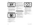
Winter Operation
Remove shroud
N
Move the Master Control lever to the
stop position 0
N
Push the hand guard forwards – the
saw chain is blocked
Loosen screws (1)
N
Remove the shroud (2)
N
Refit the shroud and tighten the
screws
At temperatures above +20 °C
N
Ensure that the slide is set back to
position s (summer operation)
without fail, otherwise the engine
may malfunction due to overheating
if the chain saw is extremely cold
(frost formation) – after starting,
bring the engine up to operating
temperature at increased idle speed
(disengage chain brake!)
Cover plate
The cover plate (special accessory)
keeps out powdered or drifting snow.
When the cover plate is used, the slide
must be in the winter position.
If engine trouble occurs, first check
whether use of the cover plate is
necessary.
Attach cover plate
At temperatures below -10 °C
Pre-heat carburetor
Under extreme winter conditions
(temperatures below -10 °C, powdered
or drifting snow), it is recommended to
use the "cover plate mounting kit"
(special accessory).
At temperatures below +10 °C
In case of erratic idling behavior or poor
acceleration
0001BA002 KN
1
N
N
2
N
2
1
4903BA004 KN
N
4903BA002 KN
2
1
Place the slide in the position r
(winter operation) – r facing
upwards
Heated air is now drawn in from around
the cylinder and circulates around the
carburetor – this helps prevent
carburetor icing.
1
1
N
N
Insert cover plate (1) with both tabs
(arrows) and fasten with the
screws (2)
Turn the low speed screw (L)
1/4 turn counterclockwise
Pull the slide (1) out of the
position s (summer operation)
MS 311, MS 391
21
English
Starting / Stopping the
Engine
Positions of the Master Control lever
Adjust Master Control lever
Holding the chain saw
To adjust the Master Control lever from
the operating position F to cold start l,
press and hold down the throttle trigger
lockout and throttle trigger
simultaneously – set Master Control
lever.
There are two ways to hold the chain
saw during starting.
On the ground
To set the Master Control lever to warm
start n, first set it to cold start l, then
push the Master Control lever into the
warm start n position.
STOP
0
Switching to the warm start n position
is only possible from the cold start l
position.
Stop 0 – engine off – ignition is switched
off
To switch off the engine, set the Master
Control lever to Stop 0.
Position choke shutter closed l
–
if engine is cold
Operating position F – engine is
running or can start
–
if the engine stalls during opening of
throttle after starting
Warm start n – this position is for
starting the warm engine – the Master
Control lever returns to the operating
position when the throttle trigger is
squeezed
–
if the fuel tank has run empty
(engine stalled out)
N
Place the chain saw securely on the
ground – assume a steady stance –
the saw chain must not touch any
objects and also must not touch the
ground
N
With the left hand on handlebar,
press the chain saw firmly against
the ground – thumb wrapped
around the handlebar
N
Place your right foot through the
rear handle
Position starting acceleration n
–
Cold start l – this position is for
starting the cold engine
22
0001BA017 KN
001BA140 KN
Simultaneously pressing the throttle
trigger lockout and blipping the throttle
trigger causes the Master Control lever
to jump from the warm start n position
to the operating position F.
if engine is warm (once the engine
has been running for approx. one
minute)
–
when the engine has turned over for
the first time
–
after ventilation of the combustion
chamber, if the engine was flooded
MS 311, MS 391
English
Between the knees or thighs
0001BA020 KN
Starting
N
The decompression valve is closed
automatically when the engine starts for
the first time. For this reason, press the
button again before each additional
starting procedure.
grip the handlebar firmly with the left
hand – thumb wrapped around the
handlebar
N
with the right hand, pull the starter
grip slowly until you feel it engage –
and then give it a brisk strong pull –
simultaneously press down on the
handlebar – do not pull the starter
rope out all the way – risk of
breakage! Do not let the starter grip
snap back – guide it slowly back into
the housing so that it can rewind
properly
0
1
4
With a new engine or after a long period
of disuse, with machines without an
additional manual fuel pump, it may be
necessary to pull the starter rope several
times - to prime the fuel line.
Starting the chain saw
There must not be anyone within
the swivel range of the chain saw.
MS 311, MS 391
2
3
0001BA021 KN
N
clamp the rear handle between the
knees or thighs
0001BA019 KN
0001BA018 KN
N
Press the button, the
decompression valve will be
opened
N
Push the hand guard (1) forwards –
the saw chain is blocked
N
Simultaneously press the throttle
trigger lockout (2) and throttle
trigger (3) – set master control
lever (4)
23
English
Position choke shutter closed l
–
Once the engine is running
if engine is cold (even if the engine
has stalled during opening of
throttle after starting)
At very low outside temperatures
Position starting acceleration n
N
1
if engine is warm (once the engine
has been running for approx. one
minute)
2
Hold and start the chain saw
When the engine has turned over for
the first time
N
STOP
Press the throttle trigger lockout and
blip the throttle trigger (2); the
Master Control lever (1) jumps to
the operating position F and the
engine begins to idle
0
Move the Master Control lever (1) to
the position starting acceleration n
N
Press the button on the
decompression valve
N
Hold and start the chain saw
24
001BA186 KN
N
N
if necessary, configure for winter
operation, see "Winter Operation"
Switch off engine
N
Move the Master Control lever to the
stop position 0
If the Master Control lever was moved
from the position starting
acceleration n to the stop position 0 –
afterwards simultaneously press the
throttle trigger lockout and the throttle
trigger.
If the engine does not start
0001BA022 KN
1
let the engine warm up briefly with
the throttle slightly open
0
0001BA023 KN
–
N
STOP
N
The Master Control lever was not
returned from the position choke shutter
closed l to starting acceleration n in
time, the engine may be flooded.
Pull the hand guard toward the
handlebar
N
Move the Master Control lever to the
stop position 0
The chain brake is released – the chain
saw is ready for use.
N
Remove the spark plug – see
"Spark plug"
Open the throttle only when the
chain brake is off. Increased
engine speeds with the chain
brake on (saw chain is stationary)
will quickly damage the clutch and
chain brake.
N
Dry spark plug
N
Crank the engine several times with
the starter – to clear the combustion
chamber
N
Replace the spark plug – see
"Spark plug"
N
Set the Master Control lever to
starting acceleration n – even if
the engine is cold
MS 311, MS 391
English
N
Press the button on the
decompression valve
N
Restart the engine
Operating Instructions
During the break-in period
A factory new machine should not be run
at high revs (full throttle off load) for the
first three tank fillings. This avoids
unnecessarily high loads during the
break-in period. As all moving parts
have to bed in during the break-in
period, the frictional resistances in the
shortblock are greater during this period.
The engine develops its maximum
power after about 5 to 15 tank fillings.
Chain cold
Tension is correct when the chain fits
snugly against the underside of the bar
but can still be pulled along the bar by
hand. Retension if necessary – see
"Tensioning the Saw Chain".
Chain at operating temperature
The chain stretches and begins to sag.
The drive links must not come out of the
bar groove on the underside of the bar –
the chain may otherwise jump off the
bar. Retension the chain – see
"Tensioning the Saw Chain".
The chain contracts as it cools
down. If it is not slackened off, it
can damage the crankshaft and
bearings.
During work
Do not make the mixture leaner to
achieve an apparent increase in
power – this could damage the
engine – see "Adjusting the
Carburetor".
Open the throttle only when the
chain brake is off. Running the
engine at high revs with the chain
brake engaged (chain locked) will
quickly damage the shortblock
and chain drive (clutch, chain
brake).
Check chain tension frequently
A new saw chain must be retensioned
more frequently than one that has been
in use already for an extended period.
MS 311, MS 391
After a long period of full-throttle
operation
After a long period of full-throttle
operation, allow engine to run for a while
at idle speed so that the heat in the
engine can be dissipated by flow of
cooling air. This protects enginemounted components (ignition,
carburetor) from thermal overload.
After finishing work
N
Slacken off the chain if you have
retensioned it at operating
temperature during work.
Always slacken off the chain again
after finishing work. The chain
contracts as it cools down. If it is
not slackened off, it can damage
the crankshaft and bearings.
25
English
Long-term storage
See "Storing the machine"
Oil Quantity Control
Taking Care of the Guide
Bar
Adjustable flow oil pump is a special
option.
Different quantities of oil are required for
different bar lengths, types of wood and
cutting techniques.
1
2
Use the adjusting screw (1) (on
underside of machine) to vary the oil
feed rate as required.
Ematic position (E), medium oil flow rate
–
N
1
N
Turn the bar over – every time you
sharpen the chain and every time
you replace the chain – this helps
avoid one-sided wear, especially at
the nose and underside of the bar.
N
Regularly clean the oil inlet hole (1),
the oilway (2) and the bar
groove (3).
N
Measure the groove depth – with
the scale on the filing gauge (special
accessory) – in the area used most
for cutting.
turn the adjusting screw to "E"
(Ematic position).
To increase oil feed –
N
turn the adjusting screw clockwise.
Turn reduce oil feed –
N
turn the adjusting screw
counterclockwise.
The chain must always be wetted
with a film of lubricant.
3
143BA026 KN
Wait for engine to cool down. Keep the
machine with a full tank of fuel in a dry
place, well away from sources of
ignition, until you need it again.
001BA157 KN
Short-term storage
Chain type Pitch
Picco
Rapid
Rapid
Rapid
26
Minimum
groove depth
3/8" P
5.0 mm
1/4“
4.0 mm
3/8“; 0.325“ 6.0 mm
0.404“
7.0 mm
MS 311, MS 391
English
N
Replace the guide bar.
The drive link tangs will otherwise
scrape along the bottom of the groove –
the cutters and tie straps will not ride on
the bar rails.
Air Filter System
The air filter system can be adapted to
different operating conditions by the
insertion of different air filters.
Retrofitting is simple.
Depending on equipment version, the
machine is equipped with a fleece filter,
a fleece filter with a felt prefilter or a
fabric filter.
Cleaning the Air Filter
If there is a noticeable loss of engine
power
Remove shroud
N
Move the Master Control Lever to
the stop position 0
N
Push the front hand guard forwards
– the saw chain is blocked
Fleece filter
1
For normal or dry applications.
Fleece filter with felt prefilter
2
1
For very dusty operating environments.
1
Fabric filter
For extreme winter conditions (e.g.,
powdered or drifting snow or frost
formation).
N
Loosen screws (1)
N
Remove the shroud (2)
4903BA002 KN
If groove depth is less than specified:
Remove air filter
N
Clean away loose dirt from around
the filter
Do not use tools to remove and
install the air filter – the air filter
could be damaged in the process.
MS 311, MS 391
27
English
Do not clean fleece filters with a
brush!
N
Push the clip (1) up and to the rear
and tilt the air filter toward the rear
handle and remove it
N
Always replace a damaged filter
The felt prefilter protects the fleece filter
and increases its service life. Thus it
should be replaced at shorter intervals
than the fleece filter.
Installing the air filter
1
0001BA012 KN
2
The carburetor comes from the factory
with a standard setting.
2
N
Insert the lugs (1) into the
recesses (2)
N
Tilt the air filter toward the filter
housing and close the clip
N
Refit the shroud and tighten the
screws
With this carburetor it is only possible to
correct the adjusting screws within fine
limits.
If the setting is too lean there is a
risk of engine damage due to
insufficient lubrication and
overheating.
Standard setting
Separate felt filter (1) from fleece
filter (2) – clean, see "Cleaning the
air filter"
Cleaning the air filter
N
Knock out the filter or blow it clear
with compressed air from the inside
outwards
In case of stubborn dirt:
N
28
Wash the filter in STIHL specialpurpose cleaner (special
accessories) or a clean, nonflammable cleaning liquid (e.g.,
warm soapy water) and dry it
0001BA008 KN
N
General Information
This setting provides an optimum fuel-air
mixture under most operating
conditions.
For versions with "fleece filter with felt
prefilter"
1
Adjusting the Carburetor
0001BA007 KN
4903BA006 KN
1
LA
N
Shut off the engine
N
Check the air filter and clean or
replace if necessary.
N
Check the spark arresting screen
(country-specific) in the muffler and
clean or replace if necessary.
MS 311, MS 391
English
Turn the high speed screw (H)
counterclockwise as far as stop (no
more than 3/4 turn).
Fine tuning for operation at high
altitude
N
Turn the low speed screw (L)
carefully clockwise as far as stop,
then turn it back 1 full turn.
A slight correction of the setting may be
necessary if the engine does not run
satisfactorily:
Adjusting idle speed
Engine stops while idling
N
Open the low speed screw (L) one
full turn.
N
Turn the idle speed screw (LA)
clockwise until the chain begins to
run – then back it off 1 1/2 turns.
N
Turn high speed screw (H)
clockwise (leaner) – no further than
stop.
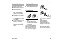
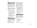
Spark Arresting Screen in
Muffler
In some countries the muffler is
equipped with a spark arresting screen.
N
If the engine is down on power,
check the spark arresting screen in
the muffler.
N
Wait for the muffler to cool down.
If the setting is too lean there is a
risk of engine damage due to
insufficient lubrication and
overheating.
1
2
Chain runs when engine is idling
0001BA009 KN
N
N
Open the low speed screw (L) one
full turn.
N
Take out the screw (1).
N
Turn the idle speed screw (LA)
counterclockwise until the chain
begins to run – then turn it another
1 1/2 turns in the same direction.
N
Pull out the spark arresting
screen (2).
N
Clean the spark arresting screen. If
the screen is damaged or heavily
carbonized, fit a new one.
N
Refit the spark arresting screen.
N
Insert the screw and tighten it down.
If the chain continues moving
when the engine is idling, have
your saw checked and repaired by
your servicing dealer.
Erratic idling behavior, poor
acceleration (even though low speed
screw is open one turn)
N
Idle setting is too lean: Turn the low
speed screw (L) counterclockwise
until the engine runs and
accelerates smoothly.
It is usually necessary to change the
setting of the idle speed screw (LA) after
every correction to the low speed
screw (L).
MS 311, MS 391
29
English
Spark Plug
N
Fit a new spark plug after about 100
operating hours – or sooner if the
electrodes are badly eroded. Install
only suppressed spark plugs of the
type approved by STIHL – see
"Specifications".
1
N
Pull off the spark plug boot
N
Unscrew spark plug
N
Push the hand guard forwards – the
saw chain is blocked
Install spark plug
1
A
1
1
N
Remove the shroud (2)
30
4903BA002 KN
2
4903BA008 KN
Move the Master Control lever to the
stop position 0
000BA039 KN
N
Loosen screws (1)
If the spark plug comes with a
detachable adapter nut (1), screw
the adapter onto the thread and
tighten it down firmly to reduce
the risk of arcing and fire.
Checking the spark plug
Remove the spark plug
N
000BA045 KN
If the engine is down on power,
difficult to start or runs poorly at idle
speed, first check the spark plug.
4903BA007 KN
N
N
Clean dirty spark plug.
N
Check electrode gap (A) and
readjust if necessary – see
"Specifications".
N
Screw in the spark plug and press
on the spark plug boot
Rectify the problems which have
caused fouling of the spark plug.
N
Refit the shroud and tighten the
screws
N
Possible causes are:
–
Too much oil in fuel mix.
–
Dirty air filter.
–
Unfavorable running conditions.
MS 311, MS 391
English
Replacing the Starter Rope
and Rewind Spring
Replace torn starter rope
2
Remove shroud
3
N
Push the hand guard forwards – the
saw chain is blocked
1
2
1
N
Loosen screws (1)
N
Remove the shroud (2)
Carefully press the spring clip (2) off
of the axle with a screw driver or
suitable pliers
N
Carefully remove the rope rotor with
washer (3) and pawls (4)
The rewind spring can jump out –
risk of injury!
N
Lever the rope out of the starter
handle with a screwdriver
N
Remove the remainder of the rope
from the rotor and starter handle
1
1
N
Remove screws (1)
N
Push hand guard upward
N
Pull the bottom of the fan housing
away from the crankcase and
remove downwards
MS 311, MS 391
5
6
7
N
Thread the rope from above through
the rope guide bush (5) and rope
rotor (6) and secure with a simple
knot
N
Coat the bearing bore in the rope
rotor with non-resinous oil
N
Slip the rope rotor onto the starter
post (7) – turn it back and forth a
little until the anchor loop of the
rewind spring engages
213BA018 KN
1
4903BA005 KN
Removing the fan housing
1
4
N
4903BA002 KN
1
4
213BA020 KN
Move the Master Control lever to the
stop position 0
001BA096 KN
N
N
Thread the new starter rope through
the starter handle and secure it by
making a special knot
N
Pull the knot into the starter handle
31
English
The starter grip must be drawn firmly
into the rope guide bush. If it tips
sideways: increase the spring tension by
another turn.
3
4
001BA096 KN
4
N
Refit the pawls (4) in the rotor and
slip the washer (3) over the starter
post
N
Press the spring clip (2) on to the
starter post and over the pegs of the
pawl with a screwdriver or suitable
pliers – the spring clip must point in
the clockwise direction – as in the
picture
It must be possible to turn the rope rotor
on another half-turn when the rope has
been drawn out completely. If not, the
spring has been tensioned too tightly
and may break!
N
Remove one turn of the rope from
the rotor
N
Install the fan housing
N
Refit the shroud and tighten the
screws
Remove the rope rotor as described
for "Replace torn starter rope"
213BA021 KN
The broken pieces of spring may
still be under tension and can
spring apart unexpectedly on
removal from the fan housing –
risk of injury! Wear face shield and
protective gloves
N
Make a loop in the unwound starter
rope and use it to turn the rope rotor
six full revolutions in the direction of
the arrow
N
Hold the rope rotor tight – pull out
the twisted rope and untangle it
N
Release the rope rotor
N
Slowly let go of rope so that it winds
onto the rotor
32
N
Position the replacement spring
with frame in the fan housing – the
anchor loop (arrow) must be located
over the retaining lug in the fan
housing
N
Apply suitable tools (screwdriver,
punch, etc.) to the recesses and
push the spring into its seat in the
fan housing – the spring slides out
of the frame
N
Refit the rope rotor, tension the
rewind spring
N
Install the fan housing
N
Refit the shroud and tighten the
screws
Replacing broken rewind spring
N
Tension the rewind spring
213BA022 KN
2
N
Carefully pry out the broken pieces
of spring with a screwdriver
N
Apply a few drops of non-resinous
oil to the new replacement spring
MS 311, MS 391
English
For periods of 3 months or longer
N
N
Remove chain sprocket cover, saw
chain and guide bar.
Drain and clean the fuel tank in a
well ventilated area.
N
Dispose of fuel properly in
accordance with local
environmental requirements.
Fit new chain sprocket
6
Release chain brake – pull hand
guard against the front handle
Remove the saw chain and guide
bar, clean them and spray with
corrosion inhibiting oil.
N
Thoroughly clean the machine –
pay special attention to the cylinder
fins and air filter.
N
If you use a biological chain and bar
lubricant, e.g. STIHL BioPlus,
completely fill the chain oil tank.
Store the machine in a dry, high or
locked location, out of the reach of
children and other unauthorized
persons.
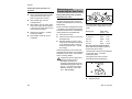
4
3
6
2
1
–
–
after use of two saw chains or
earlier
if the wear marks (arrows) are
deeper than 0.5 mm – otherwise the
service life of the saw chain is
reduced – use check gauge (special
accessory) to test
Using two saw chains in alternation
helps preserve the chain sprocket.
STIHL recommends use of original
STIHL chain sprockets in order to
ensure optimal functioning of the chain
brake.
MS 311, MS 391
2
1
Run the engine until the carburetor
is dry – this helps prevent the
carburetor diaphragms sticking
together.
N
N
N
5
001BA121 KN
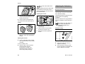
N
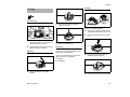
Checking and Replacing
the Chain Sprocket
001BA122 KN
Storing the Machine
N
Use a screwdriver to remove the Eclip (1)
N
Remove the washer (2)
N
Remove rim sprocket (3)
N
Inspect transport profile on the
clutch drum (4) – if there are also
heavy signs of wear, also replace
the clutch drum
N
Remove clutch drum or spur chain
sprocket (5) including needle
cage (6) from the crankshaft – with
QuickStop Super chain brake, press
throttle lock beforehand
33
English
Clean crankshaft stub and needle
cage and lubricate with STIHL
lubricant (special accessory)
N
Slide needle cage onto the
crankshaft stub
N
After refitting, turn the clutch drum
and/or spur chain sprocket approx.
1 full turn so that the carrier for the
oil pump drive engages
N
Refit the rim sprocket – cavities
toward the outside
N
Refit washer and E-clip on the
crankshaft
a
Sawing effortlessly with a properly
sharpened saw chain
A properly sharpened saw chain cuts
through wood effortlessly even with very
little pushing.
Never use a dull or damaged saw chain
– this leads to increased physical strain,
increased vibration load, unsatisfactory
cutting results and increased wear.
N
Clean the saw chain
N
Check the saw chain for cracks and
damaged rivets.
N
Replace damaged or worn chain
components and adapt these parts
to the remaining parts in terms of
shape and level of wear – rework
accordingly.
Carbide-tipped (Duro) saw chains are
especially wear-resistant. For an optimal
sharpening result, STIHL recommends
STIHL servicing dealers.
Compliance with the angles and
dimensions listed below is
absolutely necessary. An
improperly sharpened saw chain –
especially depth gauges that are
too low – can lead to increased
kickback tendency of the chain
saw – risk of injury!
689BA027 KN
N
Maintaining and
Sharpening the Saw Chain
The chain pitch marking (a) is embossed
in the area of the depth gauge of each
cutter.
Marking (a)
1/4 or 1
P, PM or 6
325 or 2
3/8 or 3
404 or 4
Chain pitch
Inches mm
1/4
6.35
3/8 P
9.32
0.325
8.25
3/8
9.32
0.404
10.26
Use only special saw chain files!
Other files are unsuitable in terms of
shape and type of cutting.
The diameter of file to be used depends
on the chain pitch – see table
"Sharpening tools"
The angles of the cutter must be
maintained during resharpening.
A
B
A
B
34
689BA021 KN
Install spur chain sprocket / rim
sprocket
Sharpening angle
Side plate angle
MS 311, MS 391
English
75
Tooth shapes
Micro = semi-chisel tooth
Super = chisel tooth
When the specified files and/or
sharpening tools and the proper setting
are used, the specified values for angles
A and B will be attained automatically.
Proper sharpening
N
Select sharpening tools in
accordance with chain pitch
N
Clamp guide bar if necessary
N
Block saw chain – push the hand
guard forward
N
To advance the saw chain, pull the
hand guard toward the handlebar:
The chain brake is disengaged.
With the Quickstop Super chain
brake system, additionally press the
throttle trigger lockout
689BA025 KN
The angles must be identical for all
cutters in the saw chain. Varying angles:
Rough, uneven running of the saw
chain, increased wear – even to the
point of saw chain breakage.
STIHL filing gauge (special accessory,
see table "Sharpening tools") – a
universal tool for checking sharpening
and side plate angles, depth gauge
setting, and tooth length, as well as
cleaning grooves and oil inlet holes.
Because these requirements can be met
only after sufficient, constant practice:
N
Use a file holder
Always use a file holder (special
accessory, see table "Sharpening tools")
when sharpening saw chains by hand.
File holders have markings for the
sharpening angle.
MS 311, MS 391
N
Sharpen frequently, removing little
material – two or three strokes of the
file are usually sufficient for simple
resharpening
689BA018 KN
10
90°
689BA043 KN
Rapid Micro (RM)
Rapid Super (RS)
Picco Micro (PM)
Rapid Micro X (RMX, ripping chain)
Picco Micro X (PMX, ripping chain)
To check the angles
Angle (°)
A
B
30
75
30
60
30
75
10
75
001BA203 KN
Chain Type
N
Guide the file: horizontally (at a
right angle to the side surface of the
guide bar) in accordance with the
specified angle – according to the
markings on the file holder – rest the
file holder on the tooth head and the
depth gauge
N
File only from the inside outward
N
The file only sharpens on the
forward stroke – lift the file on the
backstroke
N
Do not file tie straps and drive links
N
Rotate the file a little periodically in
order to avoid uneven wear
N
To remove file burr, use a piece of
hardwood
N
Check angle with file gauge
All cutters must be equally long.
35
English
With varying cutter lengths, the cutter
heights also vary and cause rough
running of the saw chain and chain
breakage.
All cutters must be filed down equal
to the length of the shortest cutter –
ideally, one should have this done in
the workshop using an electric
sharpener
The depth gauge setting is lowered
when the cutter is sharpened.
N
Check the depth gauge setting after
each sharpening
689BA044 KN
N
Lowering the depth gauges
N
1
a
689BA023 KN
N
a
Depth gauges that are too low
increase the kickback tendency of
the chain saw.
Lay the appropriate file gauge for
the chain pitch (1) on the saw chain
and press it against the cutter to be
checked – if the depth gauge
protrudes past the file gauge, the
depth gauge must be reworked
Required distance between depth
gauge and cutting edge
Chain pitch
Inches
1/4
3/8 P
0.325
3/8
0.404
Depth gauge
Distance (a)
(mm)
mm
(Inches)
(6.35) 0,65
(0.026)
(9.32) 0,65
(0.026)
(8.25) 0,65
(0.026)
(9.32) 0,65
(0.026)
(10.26) 0,80
(0.031)
689BA051 KN
When cutting softwood outside of the
frost season, the distance can be
increased by up to 0.2 mm (0.008").
36
Afterwards, dress the leading edge
of the depth gauge parallel to the
service mark (see arrow) – when
doing this, be careful not to further
lower the highest point of the depth
gauge
689BA052 KN
The depth gauge determines the depth
to which the cutter penetrates the wood
and thus the chip thickness.
689BA047 KN
Depth gauge setting
N
Rework the depth gauge so that it is
flush with the file gauge
N
Lay the file gauge on the saw chain
– the highest point of the depth
gauge must be flush with the file
gauge
RSC3, RMC3, PMC3, PMMC3
The upper part of the humped drive link
(with service mark) is lowered at the
same time as the depth gauge of the
cutter.
The rest of the humped drive link
must not be filed; otherwise, this
could increase the tendency of the
chain saw to kick back.
MS 311, MS 391
English
N
After sharpening, clean the saw
chain thoroughly, removing any
filings or grinding dust – lubricate
the saw chain thoroughly
N
In the event of extended periods of
disuse, store saw chains in cleaned
and oiled condition
Sharpening tools (special accessories)
Chain pitch
Round file ^ Round file
Inches
(mm)
mm (Inches) Part number
1/4
(6.35) 4.0 (5/32)
5605 772 4006
3/8 P
(9.32) 4.0 (5/32)
5605 772 4006
0.325
(8.25) 4.8 (3/16)
5605 772 4806
3/8
(9.32) 5.2 (13/64) 5605 772 5206
0.404
(10.26) 5.5 (7/32)
5605 772 5506
1)
File holder
Part number
5605 750 4327
5605 750 4327
5605 750 4328
5605 750 4329
5605 750 4330
File gauge
Part number
1110 893 4000
1110 893 4000
1110 893 4000
1110 893 4000
1106 893 4000
Taper square file
Part number
0814 252 3356
0814 252 3356
0814 252 3356
0814 252 3356
0814 252 3356
Sharpening set1)
Part number
5605 007 1027
5605 007 1027
5605 007 1028
5605 007 1029
5605 007 1030
consisting of file holder with round file, taper square file and file gauge
MS 311, MS 391
37
English
Complete machine
Throttle trigger, trigger interlock, Master
Control
Chain brake
Pickup body/filter in fuel tank
Visual inspection (condition, leaks)
X
Clean
Check operation
Check operation
X
X
X
X
Have checked by servicing dealer
X
Check
X
Clean, replace filter element
X
X
X
Clean
X
Chain oil tank
Clean
X
Check
X
Inspect, also check sharpness
X
X
Check chain tension
X
X
X
Sharpen
Check (wear, damage)
Guide bar
Air filter
X
Clean and turn over
X
Deburr
X
Antivibration elements
38
X
Check
X
Replace
Have replaced by dealer1)
X
X
Clean
Check
X
X
Replace
Chain sprocket
if required
if damaged
1)2)
Fuel tank
Saw chain
if problem
X
X
Replace
Chain lubrication
every 12 months
monthly
weekly
after each refueling stop
after finishing work or daily
The following intervals apply to normal operating conditions only. If your daily working time is longer or operating conditions are difficult (very dusty work area, resinrich wood, tropical wood, etc.), shorten the specified intervals accordingly. If you only
use the saw occasionally, extend the intervals accordingly.
before starting work
Maintenance and Care
X
X
X
X
X
MS 311, MS 391
if required
if damaged
if problem
every 12 months
monthly
weekly
after each refueling stop
after finishing work or daily
The following intervals apply to normal operating conditions only. If your daily working time is longer or operating conditions are difficult (very dusty work area, resinrich wood, tropical wood, etc.), shorten the specified intervals accordingly. If you only
use the saw occasionally, extend the intervals accordingly.
before starting work
English
Cooling inlets
Clean
X
Air inlet on fan housing
Clean
X
X
X
Cylinder fins
Clean
X
X
X
Preseparator port and carburetor body
Clean
X
"Carb preheat" shutter and preheating port Clean (winter operation only)
Carburetor
Check idle adjustment – chain must not
rotate
X
X
X
Readjust idle
Spark plug
X
Readjust electrode gap
X
Replace after every 100 operating hours
All accessible screws and nuts (not adjustRetighten
ing screws) 3)
Spark arresting screen4) in muffler
Chain catcher
Safety labels
1)
2)
3)
4)
X
Check
X
Clean or replace
Check
X
X
Replace
X
Replace
X
STIHL recommends a STIHL servicing dealer.
see chapter on "Chain Brake"
Firmly tighten down the cylinder base screws of chain saws (3.4 kW or more) after 10 to 20 hours of operation.
not in all versions, market-specific
MS 311, MS 391
39
English
Minimize Wear and Avoid
Damage
Observing the instructions in this manual
helps reduce the risk of unnecessary
wear and damage to the power tool.
The power tool must be operated,
maintained and stored with the due care
and attention described in this owner's
manual.
servicing dealer. STIHL dealers are
regularly given the opportunity to attend
training courses and are supplied with
the necessary technical information.
If these maintenance operations are not
carried out as specified, the user
assumes responsibility for any damage
that may occur. Among other parts, this
includes:
–
Damage to the engine due to
neglect or deficient maintenance
(e.g. air and fuel filters), incorrect
carburetor adjustment or
inadequate cleaning of cooling air
inlets (intake ports, cylinder fins).
–
Corrosion and other consequential
damage resulting from improper
storage.
–
Damage to the machine resulting
from the use of poor quality
replacement parts.
The user is responsible for all damage
caused by non-observance of the safety
precautions, operating and maintenance
instructions in this manual. This includes
in particular:
–
Alterations or modifications to the
product not approved by STIHL.
–
Using tools or accessories which
are neither approved or suitable for
the product or are of a poor quality.
–
Using the product for purposes for
which it was not designed.
–
Using the product for sports or
competitive events.
–
Consequential damage caused by
continuing to use the product with
defective components.
Maintenance Work
Parts Subject to Wear and Tear
Some parts of the power tool are subject
to normal wear and tear even during
regular operation in accordance with
instructions and, depending on the type
and duration of use, have to be replaced
in good time. Among other parts, this
includes:
All the operations described in the
"Maintenance Chart" must be performed
on a regular basis. If these maintenance
operations cannot be performed by the
owner, they should be performed by a
servicing dealer.
–
Saw chain, guide bar
–
Drive components (clutch, clutch
drum, chain sprocket)
–
Filters (air, oil, fuel)
–
Starter mechanism
STIHL recommends that you have
servicing and repair work carried out
exclusively by an authorized STIHL
–
Spark plug
–
Components of antivibration system
40
MS 311, MS 391
English
Main Parts
1
2
3
4
3
2
1
5
6
7
8
9
10
11
12
13
14
15
16
17
18
19
20
21
22
23
24
#
5
#
4
6
11
7
12
10
8
13
9
17
16
15
20
18
22
19
23
21
24
4903BA003 KN
14
Shroud catch
Carburetor adjusting screws
Spark plug boot
Slide (summer operation and winter
operation)
Decompression valve
Chain brake
Chain sprocket
Chain sprocket cover
Chain catcher
Side access chain tensioner
Bumper spike
Guide bar
Oilomatic saw chain
Oil filler cap
Muffler
Front hand guard
Front handle (handlebar)
Starter grip
Fuel tank twist lock
Master Control lever
Throttle trigger
Throttle trigger interlock
Rear handle
Rear hand guard
Serial number
MS 311, MS 391
41
English
Fuel system
Specifications
Chain sprockets
All position diaphragm carburetor with
integral fuel pump
Engine
Fuel tank capacity:
STIHL single cylinder two-stroke engine
59.0 cm3
47 mm
34 mm
3.1 kW (4.2 HP)
at 9500 rpm
2800 rpm
13000 rpm
MS 391
Displacement:
Bore:
Stroke:
Engine power to
ISO 7293:
Idle speed:
Maximum permissible
speed with bar and
chain:
cm3
64.1
49 mm
34 mm
3.3 kW (4.5 HP)
at 9500 rpm
2800 rpm
13000 rpm
Chain lubrication
Electronic magneto ignition
Spark plug
(suppressed):
Electrode gap:
42
Fully automatic, speed-controlled oil
pump with reciprocating piston additional manual oil flow control
Oil tank capacity:
0.350 l
Bosch WSR 6 F,
NGK BPMR 7 A
0.5 mm
The idle, full-throttle and nominal
maximum speed are given equal
consideration when calculating sound
and vibration levels.
For further details concerning
compliance with the employers'
Directive on vibration 2002/44/EC, see
www.stihl.com/vib/
Weight
Sound pressure level Lpeq to
ISO 22868
dry, without bar and chain
MS 311:
MS 391:
MS 311:
MS 391:
6.4 kg
6.4 kg
105 dB(A)
105 dB(A)
Sound power level Lweq to ISO 22868
Cutting attachment
MS 311:
MS 391:
Rollomatic E guide bars
Vibration level ahv, eq to ISO 22867
Bar lengths:
Pitch:
Groove width:
Sprocket nose:
37, 40, 45 cm
3/8" (9.32 mm)
1.6 mm
10-tooth
Saw chains 3/8"
Ignition system
Sound and vibration levels
0.60 l
MS 311
Displacement:
Bore:
Stroke:
Engine power to
ISO 7293:
Idle speed:
Maximum permissible
speed with bar and
chain:
7-tooth for 3/8" (rim sprocket)
Rapid Micro Comfort (36 RMC)
Rapid Super Comfort (36 RSC)
Rapid Super Comfort 3 (36 RSC3)
Pitch:
3/8" (9.32 mm)
Drive link gauge:
1.6 mm
MS 311:
MS 391:
115 dB(A)
115 dB(A)
Handle,
Handle, left right
4,0 m/s2
4,0 m/s2
2
4,0 m/s
4,0 m/s2
The K-factor in accordance with
Directive 2006/42/EC is 2.5 dB(A) for
the sound pressure level and sound
power level; the K-factor in accordance
with Directive 2006/42/EC is 2.0 m/s2
for the vibration measurement.
MS 311, MS 391
English
REACH
Special Accessories
REACH is an EC regulation and stands
for the Registration, Evaluation,
Authorisation and Restriction of
Chemical substances.
Chain scabbard
For information on compliance with the
REACH regulation (EC) No. 1907/2006
see www.stihl.com/reach.
If you use guide bars of different lengths
on the saw, the length of the chain
scabbard must be matched to the guide
bar to help reduce the risk of injury.
–
STIHL lubricating grease
–
STIHL filler nozzle for fuel – helps
avoid spills and overfilling during
refueling
–
STIHL filler nozzle for chain oil –
helps avoid spills and overfilling
Contact your STIHL dealer for more
information on these and other special
accessories.
If the chain scabbard does not cover the
full length of the guide bar, a suitable
chain scabbard or a scabbard extension
is necessary.
Depending on the model, the scabbard
extension either comes standard with
the saw or is available as a special
accessory.
Fitting the chain scabbard extension
1
cm
1
N
001BA207 KN
INCH
Push the scabbard extension,
locking tabs (1) first, onto the
scabbard until the required length is
obtained.
Other special accessories
MS 311, MS 391
–
File holder with round file
–
Filing gauge
–
Reference gauges
43
English
Ordering Spare Parts
Maintenance and Repairs
EC Declaration of
Conformity
Please enter your saw model, serial
number as well as the part numbers of
the guide bar and saw chain in the
spaces provided. This will make reordering simpler.
Users of this machine may only carry out
the maintenance and service work
described in this user manual. All other
repairs must be carried out by a
servicing dealer.
ANDREAS STIHL AG & Co. KG
Badstr. 115
D-71336 Waiblingen
The guide bar and saw chain are subject
to normal wear and tear. When
purchasing these parts, always quote
the saw model, the part numbers and
names of the parts.
STIHL recommends that you have
servicing and repair work carried out
exclusively by an authorized STIHL
servicing dealer. STIHL dealers are
regularly given the opportunity to attend
training courses and are supplied with
the necessary technical information.
Model:
Make:
Type:
Model
Serial number
Guide bar part number
Chain part number
When repairing the machine, only use
replacement parts which have been
approved by STIHL for this power tool or
are technically identical. Only use highquality replacement parts in order to
avoid the risk of accidents and damage
to the machine.
STIHL recommends the use of original
STIHL replacement parts.
Original STIHL parts can be identified by
the STIHL part number, the {
logo and the STIHL parts symbol K
(the symbol may appear alone on small
parts).
hereby confirms that
Serial identification
number:
Displacement
MS 311:
MS 391:
Chain saw
STIHL
MS 311
MS 391
1140
59.0 cm3
64.1 cm3
conforms to the specifications of
Directives 2006/42/EC, 2004/108/EC
and 2000/14/EC and has been
developed and built in compliance with
the following standards:
EN ISO 11681-1, EN 55012, EN 610006-1
The measured and guaranteed
equivalent sound power level has been
determined in accordance with Directive
2000/14/EC, Annex V, and standard
ISO 9207.
Measured sound power level
MS 311:
MS 391:
117 dB(A)
117 dB(A)
Guaranteed sound power level
MS 311:
MS 391:
119 dB(A)
119 dB(A)
The EC type approval test was carried
out at the
44
MS 311, MS 391
English
DPLF
Deutsche Prüf- und Zertifizierungsstelle
für Land- und Forsttechnik (NB 0363)
Max-Eyth-Weg 1
D-64823 Groß-Umstadt
Certification No.:
MS 311:
MS 391:
Quality Certification
K-EG-2009/5202
K-EG-2009/5143
The technical documentation has been
retained by:
ANDREAS STIHL AG & Co. KG
Produktzulassung
The year of construction and the serial
number are shown on the machine.
000BA025 LÄ
Waiblingen, 17.06.2010
ANDREAS STIHL AG & Co. KG
pp.
All STIHL products comply with the
highest quality standards.
Elsner
Head of Product Group Management
MS 311, MS 391
An independent organization has
certified that all products manufactured
by STIHL meet the strict requirements of
the ISO 9001 standard for quality
management systems in terms of
product development, materials
purchasing, production, assembly,
documentation and customer service.
45
0458-542-0121-B
englisch
G
www.stihl.com
*04585420121B*
0458-542-0121-B