1
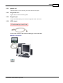
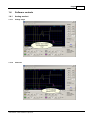
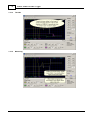
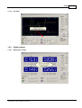
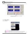
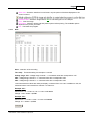
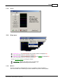
4 CHANNEL USB RECORDER / LOGGER
PCS10 / K8047
User manual
Velleman Instruments
Altough developments in the field of electronics proceed at
breakneck speed, we have always been able to create the
ideal mix between innovation and durability.
The innovations are mainly expressed in our scopes, which
are created with the aid of the latest techniques.
The velleman Instruments team
Contents
I
Table of Contents
Foreword
3
Part I English
1 General
................................................................................................................................... 3
Specifications .. ... .... ... .... .... ... .... ... .... ... .... ... .... .... ... .... ... .... ... .... ... .... .... ... .... ... .... ... .... ... .... .... ... .... ... .... ... .... .................
System requirements
.. ... .... ... .... .... ... .... ... .... ... .... ... .... .... ... .... ... .... ... .... ... .... .... ... .... ... .... ... .... ... .... .... ... .... ... .... ... .... .................
Safety & Warnings
.. ... .... ... .... .... ... .... ... .... ... .... ... .... .... ... .... ... .... ... .... ... .... .... ... .... ... .... ... .... ... .... .... ... .... ... .... ... .... .................
Warranty
.. ... .... ... .... .... ... .... ... .... ... .... ... .... .... ... .... ... .... ... .... ... .... .... ... .... ... .... ... .... ... .... .... ... .... ... .... ... .... .................
3
3
3
4
2 Connections ................................................................................................................................... 4
power led
.. ... .... ... .... .... ... .... ... .... ... .... ... .... .... ... .... ... .... ... .... ... .... .... ... .... ... .... ... .... ... .... .... ... .... ... .... ... .... .................
diagnostic led .. ... .... ... .... .... ... .... ... .... ... .... ... .... .... ... .... ... .... ... .... ... .... .... ... .... ... .... ... .... ... .... .... ... .... ... .... ... .... .................
Signal input .. ... .... ... .... .... ... .... ... .... ... .... ... .... .... ... .... ... .... ... .... ... .... .... ... .... ... .... ... .... ... .... .... ... .... ... .... ... .... .................
USB output .. ... .... ... .... .... ... .... ... .... ... .... ... .... .... ... .... ... .... ... .... ... .... .... ... .... ... .... ... .... ... .... .... ... .... ... .... ... .... .................
5
5
5
5
3 Readout screens
................................................................................................................................... 6
Analog screen .. ... .... ... .... .... ... .... ... .... ... .... ... .... .... ... .... ... .... ... .... ... .... .... ... .... ... .... ... .... ... .... .... ... .... ... .... ... .... ................. 6
Digital screen .. ... .... ... .... .... ... .... ... .... ... .... ... .... .... ... .... ... .... ... .... ... .... .... ... .... ... .... ... .... ... .... .... ... .... ... .... ... .... ................. 6
4 Software controls
................................................................................................................................... 7
Analog readout.. ... .... ... .... .... ... .... ... .... ... .... ... .... .... ... .... ... .... ... .... ... .... .... ... .... ... .... ... .... ... .... .... ... .... ... .... ... .... ................. 7
Voltage range
. ... .... ... .... .... ... .... ... .... ... .... ... .... .... ... .... ... .... ... .... ... .... .... ... .... ... .... ... .... ... .... .... ... .... ... .... ... .... ................. 7
Channels . ... .... ... .... .... ... .... ... .... ... .... ... .... .... ... .... ... .... ... .... ... .... .... ... .... ... .... ... .... ... .... .... ... .... ... .... ... .... ................. 7
Time/div . ... .... ... .... .... ... .... ... .... ... .... ... .... .... ... .... ... .... ... .... ... .... .... ... .... ... .... ... .... ... .... .... ... .... ... .... ... .... ................. 8
Measuring . ... .... ... .... .... ... .... ... .... ... .... ... .... .... ... .... ... .... ... .... ... .... .... ... .... ... .... ... .... ... .... .... ... .... ... .... ... .... ................. 8
Scrollbar . ... .... ... .... .... ... .... ... .... ... .... ... .... .... ... .... ... .... ... .... ... .... .... ... .... ... .... ... .... ... .... .... ... .... ... .... ... .... ................. 9
Digital readout.. ... .... ... .... .... ... .... ... .... ... .... ... .... .... ... .... ... .... ... .... ... .... .... ... .... ... .... ... .... ... .... .... ... .... ... .... ... .... ................. 9
Momentary. ...
voltage
.... ... .... .... ... .... ... .... ... .... ... .... .... ... .... ... .... ... .... ... .... .... ... .... ... .... ... .... ... .... .... ... .... ... .... ... .... ................. 9
Max. & Min.
.. ....voltage
... .... .... storage
... .... ... .... ... .... ... .... .... ... .... ... .... ... .... ... .... .... ... .... ... .... ... .... ... .... .... ... .... ... .... ... .... ... ................ 10
5 Menu options................................................................................................................................... 10
File menu
... .... ... .... .... ... .... ... .... ... .... ... .... .... ... .... ... .... ... .... ... .... .... ... .... ... .... ... .... ... .... .... ... .... ... .... ... .... ... ................ 10
Date
.. .... ... .... .... ... .... ... .... ... .... ... .... .... ... .... ... .... ... .... ... .... .... ... .... ... .... ... .... ... .... .... ... .... ... .... ... .... ... ................ 11
Edit menu ... .... ... .... .... ... .... ... .... ... .... ... .... .... ... .... ... .... ... .... ... .... .... ... .... ... .... ... .... ... .... .... ... .... ... .... ... .... ... ................ 12
Options menu... .... ... .... .... ... .... ... .... ... .... ... .... .... ... .... ... .... ... .... ... .... .... ... .... ... .... ... .... ... .... .... ... .... ... .... ... .... ... ................ 12
Colors .. .... ... .... .... ... .... ... .... ... .... ... .... .... ... .... ... .... ... .... ... .... .... ... .... ... .... ... .... ... .... .... ... .... ... .... ... .... ... ................ 13
View menu ... .... ... .... .... ... .... ... .... ... .... ... .... .... ... .... ... .... ... .... ... .... .... ... .... ... .... ... .... ... .... .... ... .... ... .... ... .... ... ................ 13
Markers .. .... ... .... .... ... .... ... .... ... .... ... .... .... ... .... ... .... ... .... ... .... .... ... .... ... .... ... .... ... .... .... ... .... ... .... ... .... ... ................ 13
Markers dV
.. ....
&...t .... .... ... .... ... .... ... .... ... .... .... ... .... ... .... ... .... ... .... .... ... .... ... .... ... .... ... .... .... ... .... ... .... ... .... ... ................ 14
Markers V.. &
....dt
... .... .... ... .... ... .... ... .... ... .... .... ... .... ... .... ... .... ... .... .... ... .... ... .... ... .... ... .... .... ... .... ... .... ... .... ... ................ 14
Move the ..markers
.... ... .... .... ... .... ... .... ... .... ... .... .... ... .... ... .... ... .... ... .... .... ... .... ... .... ... .... ... .... .... ... .... ... .... ... .... ... ................ 14
Display digital
.. .... ... .... .... ... .... ... .... ... .... ... .... .... ... .... ... .... ... .... ... .... .... ... .... ... .... ... .... ... .... .... ... .... ... .... ... .... ... ................ 15
Help menu ... .... ... .... .... ... .... ... .... ... .... ... .... .... ... .... ... .... ... .... ... .... .... ... .... ... .... ... .... ... .... .... ... .... ... .... ... .... ... ................ 15
About
.. .... ... .... .... ... .... ... .... ... .... ... .... .... ... .... ... .... ... .... ... .... .... ... .... ... .... ... .... ... .... .... ... .... ... .... ... .... ... ................ 16
6 Assistance ................................................................................................................................... 16
Troubleshooting
... .... ... .... .... ... .... ... .... ... .... ... .... .... ... .... ... .... ... .... ... .... .... ... .... ... .... ... .... ... .... .... ... .... ... .... ... .... ... ................ 16
Product support
... .... ... .... .... ... .... ... .... ... .... ... .... .... ... .... ... .... ... .... ... .... .... ... .... ... .... ... .... ... .... .... ... .... ... .... ... .... ... ................ 16
7 glossary
................................................................................................................................... 16
Administrator... .... ... .... .... ... .... ... .... ... .... ... .... .... ... .... ... .... ... .... ... .... .... ... .... ... .... ... .... ... .... .... ... .... ... .... ... .... ... ................ 16
DLL
... .... ... .... .... ... .... ... .... ... .... ... .... .... ... .... ... .... ... .... ... .... .... ... .... ... .... ... .... ... .... .... ... .... ... .... ... .... ... ................ 16
Logical printer
... .... ... .... .... ... .... ... .... ... .... ... .... .... ... .... ... .... ... .... ... .... .... ... .... ... .... ... .... ... .... .... ... .... ... .... ... .... ... ................ 17
Plug and Play... .... ... .... .... ... .... ... .... ... .... ... .... .... ... .... ... .... ... .... ... .... .... ... .... ... .... ... .... ... .... .... ... .... ... .... ... .... ... ................ 17
Port
... .... ... .... .... ... .... ... .... ... .... ... .... .... ... .... ... .... ... .... ... .... .... ... .... ... .... ... .... ... .... .... ... .... ... .... ... .... ... ................ 17
Print spooler ... .... ... .... .... ... .... ... .... ... .... ... .... .... ... .... ... .... ... .... ... .... .... ... .... ... .... ... .... ... .... .... ... .... ... .... ... .... ... ................ 17
Printer
... .... ... .... .... ... .... ... .... ... .... ... .... .... ... .... ... .... ... .... ... .... .... ... .... ... .... ... .... ... .... .... ... .... ... .... ... .... ... ................ 17
PCS10/K8047 © 2003 Velleman Components
I
II
PCS10 - K8047 recorder / Logger
Spooling
USB
Index
... .... ... .... .... ... .... ... .... ... .... ... .... .... ... .... ... .... ... .... ... .... .... ... .... ... .... ... .... ... .... .... ... .... ... .... ... .... ... ................ 17
... .... ... .... .... ... .... ... .... ... .... ... .... .... ... .... ... .... ... .... ... .... .... ... .... ... .... ... .... ... .... .... ... .... ... .... ... .... ... ................ 17
18
English
1
English
1.1
General
1.1.1
Specifications
Hardware :
•
•
•
•
•
•
•
•
•
USB connected and powered.
Four DC-coupled input channels
Input resistance 1Mohm
Maximum samples per second: 100
Four input ranges, 3V / 6V / 15V and 30V
Sensitivity 10mV
Accuracy ±3% of full scale
Maximum input 30Vdc
Power and recording/diagnostic LED
Software :
•
•
•
•
•
•
•
•
1.1.2
Analogue trace or DVM readout
4 simultaneous channels recording
Minimum / maximum sample hold function for DVM
From 1 sec to 1000 sec per division
Storage and recall of screens (full colour) or data
Automatic recording option for long time recordings
On screen markers for time and voltage
DLL included for own development
System requirements
Minimum system requirements :
•
•
•
•
•
•
IBM compatible PC
Windows 98SE, ME, Windows 2000, Windows XP.
SVGA display card (min. 800 x 600).
Mouse
Free USB port
CD-Rom player.
Software updates :
Check our web site www.velleman.be for updates (or just click on "updates").
1.1.3
Safety & Warnings
SAFETY and WARNINGS
Important safety information!
PCS10/K8047 © 2003 Velleman Components
3
4
PCS10 - K8047 recorder / Logger
GAlways remember that the ground of all the channels are interconnected !
1.1.4
Warranty
This product is guaranteed against defects in components and construction from the moment it is purchased and
for a period of ONE YEAR starting from the date of sale.
This guarantee is only valid if the unit is submitted together with the original purchase invoice. VELLEMAN
Components limits its responsibility to the reparation of defects or, as VELLEMAN Components deems
necessary, to the replacement or reparation of defective components. Costs and risks connected to the transport,
removal or placement of the product, or any other costs directly or indirectly connected to the repair, will not be
reimbursed by VELLEMAN Components. VELLEMAN Components will not be held responsible for any
damages caused by the malfunctioning of a unit.
1.2
Connections
The unit is connected to the USB port of the computer, using a USB cable.
English
1.2.1
power led
Indicates that the unit is correctly connected with the computer
1.2.2
diagnostic led
Lights when the unit is recording data.
1.2.3
Signal input
4 input channels enable you to measure 4 signals at the same time.
1.2.4
USB output
Connect the computer to the USB recorder/logger via the USB cable
Make the connections :
PCS10/K8047 © 2003 Velleman Components
5
6
PCS10 - K8047 recorder / Logger
1.3
Readout screens
1.3.1
Analog screen
K8047 / PCS10 screenshot
Using this screen the 4 channels can be viewed simultanously as a trace on the screen .
1.3.2
Digital screen
K8047 / PCS10 screenshot
Powerfull feature which allows digital visualisation of the measurements
English
1.4
Software controls
1.4.1
Analog readout
1.4.1.1
Voltage range
1.4.1.2
Channels
PCS10/K8047 © 2003 Velleman Components
7
8
PCS10 - K8047 recorder / Logger
1.4.1.3
Time/div
1.4.1.4
Measuring
English
1.4.1.5
Scrollbar
1.4.2
Digital readout
1.4.2.1
Momentary voltage
PCS10/K8047 © 2003 Velleman Components
9
10
PCS10 - K8047 recorder / Logger
1.4.2.2
Max. & Min. voltage storage
1.5
Menu options
1.5.1
File menu
Open image : Opens a image file and display it on the screen.
Open data : Opens and displays the waveform data saved in text format using the Save data
option.
Save image : Saves the image to a file in Windows Bitmap (*.BMP) format, (full color).
English
11
Save data : Saves the waveform in text format. only the portion of the data displayed on the
screen is saved.
AutoSave data : Saves the image and its date to a file during the run of a sample.
Print : Print the image.
Print setup : Selects a printer and sets printer options before printing. The available options
depend on the printer you select.
Exit : Teminates the program.
1.5.1.1
Date
Start : start time of the recording
Time step : Timescale setting 100 samples = 1second
Voltage range CH1
CH2 : Voltage range
CH3 : Voltage range
CH4 : Voltage range
: Voltage range channel 1 => measured value 255 corresponds to 15V
channel 2 => measured value 255 corresponds to 30V
channel 3 => measured value 255 corresponds to 30V
channel 4 => measured value 255 corresponds to 30V
1700 measurements values are taken per display, numbered from 0 to 1700. In addition to this, the
measured values can be read from channel 1 to channel 4.
Example CH1 :
Point in time : 13 x 1/100 = 0,13s + 9:17:02 = 9:17:02.13
Voltage : 138 x 15/255 = 8,118V
Example CH3 :
Point in time : 4 x 1/100 = 0,04s + 9:17:02 = 9:17:02.04
Voltage : 61 x 30/255 = 7,176V
Print page
PCS10/K8047 © 2003 Velleman Components
12
1.5.2
PCS10 - K8047 recorder / Logger
Edit menu
Copy : Copies the image to the windows 'clipboard'.
Paste : Pastes the image residing in windows 'clipboard' to the screen.
1.5.3
Options menu
Colors : Select the color for various items on the waveform display. To change the color of an
item, click the corresponding button. This will open a dialog in which you can select a new color.
Full color selection is possible only if True color (24bit) palette is used. There are restrictions in
the color combinations to the default settings.
Click Default colors button to resets all colors to the default settings.
Demo mode : Unit goes into demo mode, several signals are displayed.
English
1.5.3.1
Colors
1.5.4
View menu
Markers dV & t : The absolute time of the marker position is displayed. (2)
Two horizontal markers for measuring voltage (1)
Markers V & dt : The time difference between the two markers is displayed.(1)
Two horizontal markers for measuring voltage (2)
You can move the markers by using your mouse.
DVM display : Displays the digital screen recorder/logger.
Bright grid : Brightens the blue grid on the screen.
1.5.4.1
Markers
The user can perform measurements on one or 4 signals by using the markers.
This can be useful when measuring the interval between two points of the amplitude.
PCS10/K8047 © 2003 Velleman Components
13
14
PCS10 - K8047 recorder / Logger
1.5.4.2
Markers dV & t
1.5.4.3
Markers V & dt
.
1.5.4.4
Move the markers
•
•
•
•
Place the mouse pointer over a dached marker line.
Press and hold the left mouse button.
The marker line turns solid.
Drag the marker to the approriate position.
English
1.5.4.5
15
Display digital
K8047 / PCS10 screenshot
Unique feature allowing digital visualization of the max. and min. voltage peak during measurements
1.5.5
Help menu
Contents : Display the help file.
About : Displays information of the program version.
PCS10/K8047 © 2003 Velleman Components
16
PCS10 - K8047 recorder / Logger
1.5.5.1
About
1.6
Assistance
1.6.1
Troubleshooting
• If the Record Led of the Recorder/Logger unit is continuously lit at the startup:
- Disconnect and then reconnect the unit to the PC.
- The Record LED should show sequence of three blinks and then stay off until the Run button is
depressed.
1.6.2
Product support
E-mail :
[email protected]
Website :
http://www.velleman.be
1.7
glossary
1.7.1
Administrator
A person responsible for setting up and managing domain controllers or local computers and their user
and group accounts, assigning passwords and permissions, and helping users with networking issues.
Administrators are members of the Administrators group and have full control over the domain or
computer.
1.7.2
DLL
An operating system feature that allows executable routines (generally serving a specific function or
set of functions) to be stored separately as files with .dll extensions. These routines are loaded only
English
17
when needed by the program that calls them.
1.7.3
Logical printer
The software interface between the operating system and the printer in Windows. While a printer is the
device that does the actual printing, a logical printer determines how a print job is processed and how it
is routed to its destination (to a local or network port, to a file, ...). When you print a document, it is
spooled (or stored) on the logical printer before it is sent to the printer itself.
See also printer; spooling.
1.7.4
Plug and Play
A set of specifications developed by Intel that allows a computer to automatically detect and configure
a device and install the appropriate device drivers.
1.7.5
Port
Generally, a connection point on your computer where you can connect devices that pass data into and
out of a computer. For example, a printer is typically connected to a parallel port (also called an LPT
port), and a modem is typically connected to a serial port (also called a COM port).
1.7.6
Print spooler
Computer software that accepts a document sent to a printer by the user and then stores it on disk or
in memory until the printer is ready for it. This collection of dynamic-link libraries (DLLs) receives,
processes, schedules, and distributes documents for printing. The term spooler is an acronym created
from "simultaneous print operations on line."
See also DLL; spooling.
1.7.7
Printer
A device that puts text or images on paper or other print media. Examples include laser printers or dotmatrix printers.
See also logical printer; Printer; Print spooler.
1.7.8
Spooling
A process on a server in which print documents are stored on a disk until a printer is ready to process
them. A spooler accepts each document from each client, stores it, then sends it to a printer when the
printer is ready.
See also print spooler.
1.7.9
USB
An external bus that supports Plug and Play installation. Using USB, you can connect and disconnect
devices without shutting down or restarting your computer. You can use a single USB port to connect
up to 127 peripheral devices, including speakers, telephones, CD-ROM drives, joysticks, tape drives,
keyboards, scanners, and cameras. A USB port is usually located on the back of your computer near
the serial port or parallel port. Universal serial bus is also called USB.
See also Plug and Play; port.
PCS10/K8047 © 2003 Velleman Components
18
PCS10 - K8047 recorder / Logger
Index
File menu 10
full coulour 10
Full measurement range
-224bit
-F7
12
-H-
-AAbout 15
absolute time 13
Analog readout 7
Analog screen 6
AutoSave data 10
-BBeam to sweep
BMP 10
Bright grid 13
-IInput channels 4
input ranges 3
Input resistance 3
-M-
8
markers 6
Markers dV & t 13
Markers V & dt 13
Max. & Min. voltage storage 10
max. and min. voltage peak 6
Maximum input 3
Maximum voltage 10
Minimum system requirements 3
Momentary measurement
9
Momentary voltage 9
move the markers 13
-CChannels 7
Colors 12
Connections 4
Contents 15
Copy 12
-Ddate 10
DC components 3
Default colors 12
Demo mode 12
Digital screen 6
digital visualisation 6
DVM display 13
-EEarth connection
Edit menu 12
electrical signals
E-mail 16
Exit 10
Hardware 3
Help menu 15
3
6
-OON/ OFF channels 7
Open data 10
Open image 10
Options menu 12
Oscilloscope display 6
output 4
-PPaste 12
Print 10
Print setup 10
Product support
16
Index
-RRecording / diagnostic
Recurrent display 8
requirements 3
Run 8
-Z4
-SSafety & Warnings
3
Save data 10
Save image 10
scrollbar 9
Sensitivity 3
Signal input 4
Single 8
Software 3
Software updates 3
Specifications 3
System requirements 3
-Ttime difference 13
time setting 8
Time/div 8
Troubleshooting 16
True color 12
-UUSB output 4
USB power indication
4
-VV/div 7
View menu 13
Voltage range 7, 10
-WWarranty 4
Website 16
Windows 95 3
Windows NT 3
PCS10/K8047 © 2003 Velleman Components
Zoom
8
19
Velleman Instruments is a division of
Velleman Components NV.
Legen Heirweg 33
9890 Gavere
Belgium
Internet site : http://www.velleman.be
E-mail : [email protected]
© Velleman Instruments 2003_UK