1
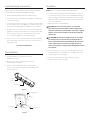
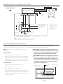
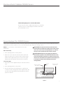
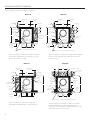
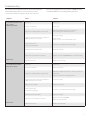
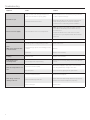
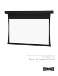
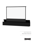
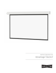
INSTRUCTION BOOK FOR
Boardroom Electrol®
Important Safety Instructions
Installation
When using your video equipment, basic safety precautions
should always be followed, including the following:
NOTE: Unit is not to be installed in air handling space.
1. Read and understand all instructions before using.
2. Position the cord so that it will not be tripped over, pulled, or
contact hot surfaces.
3. If an extension cord is necessary, a cord with a current rating
at least equal to that of the appliance should be used. Cords
rated for less amperage than the appliance may overheat.
1. Install screen by raising unit into position between joists at
one end only. Install one lag screw or appropriate fastener in
each mounting bracket. Secure opposite end. Secure center
support brackets. Install sufficient fasteners in each bracket
for secure installation.
2. Make sure unit is level and plumb.
CAUTION! Do not secure access door or seal in unit
until screen has been secured in position and properly
tested for satisfactory operation. Do not fit unit so tightly
that the screen surface drop door binds. Door drops by
gravity only.
ATTENTION! Ne fixez pas la trappe d'accès ou ne scellez
pas l'unité jusqu'à ce qu'il ait été correctement mis en
place et qu'il fonctionne convenablement. Ne serrez pas
l'unité au point que la surface de la trappe d'accès de
l'écran soit bloquée. La trappe tombe uniquement à cause
de la gravité.
4. To reduce the risk of electric shock, do not disassemble this
appliance. Contact an authorized service dealer when repair
work is required. Incorrect reassembly can cause electric
shock when the appliance is used subsequently.
5. The use of an accessory attachment not recommended by
the manufacturer may cause a risk of fire, electric shock, or
injury to persons.
Save These Instructions
Pre-Installation
3. If you are going to cover screen door with paneling or other
materials, allow access (suitable holes or plug) to slat hook
screws (4) when servicing (Fig. 1).
1. Carefully unpack screen and remove outer
wrapping from case.
4. Open access door by removing access door screws.
2. Make sure to recheck measurement of screen
location before installation.
3. Remove center support brackets (on 8' and wider
screens only), reverse brackets and reinstall flush with
the top of the box.
Slat Hook
Screws
Tape Strips
Figure 1
Mounting Brackets
Access
Door
Screw
Fabric Door
Access Door
Figure 2
2
5. Remove junction box cover plate.
Boardroom Electrol® Installation
6. Remove switch assembly (boxed, located at pin end of fabric).
a limit switch is tripped and the motor shuts off.
CAUTION! Do not cut wrapping paper or tape with knife or
any sharp tool. Remove by hand.
CAUTION! Excessive continuous operation may cause
overheating.
ATTENTION! Ne coupez pas le ruban adhésif sur la toile
avec un couteau ou un outil tranchant. Retirez à la main.
ATTENTION! Le fonctionnement continu et excessif peut
provoquer une surchauffe.
7. Pull orange string to remove wrapping paper.
8. Install electrical hook up that applies to your unit. Standard
installation is for a single 120VAC or 240VAC wall switch to
control the screen. Optional Control units may have been
ordered. Refer to additional instructions for the external VPI,
external low voltage control and SCB-100. Refer to the
appropriate wiring diagram for your screen.
12. Run picture surface downward until picture surface
door fully opens.
13. Install junction box cover plate.
14. Close access door and reinstall screws at each end
of access door.
CAUTION! Do not attempt to restore a lost wrap by
adjusting limit switches. Allow one-eighth of an inch (1/8")
clearance around surface door. Make sure door does not
bind. Check hinges. Paint or tile cement will interfere with
free operation. Gravity drops door.
ATTENTION! N'essayez pas de réintégrer un tour de toile
en réglant les interrupteurs de limite! Laissez un espace
0,30 cm (1/8 po) autour de la trappe. Vérifiez que la
trappe n'est pas entravée. Vérifiez les gonds. La peinture
ou le ciment à tuile nuira au bon fonctionnement. La
gravité fait tomber la trappe.
NOTE: Screen has been internally wired at DA-LITE. Wiring
designated “external” is completed by installer conforming to
local and national codes.
9. Lower picture surface approximately 4"-6" so that the slat will
rest on top of the slat hooks. Guide slat past hooks by gently
pulling fabric forward (Fig. 3). Do not bend hooks.
10. Test installation by carefully running picture surface up and
down 2-3 times. Be prepared to stop screen. Standard Duty
Cycle: 1 MIN. ON / 3 MIN. OFF.
11. Run the picture surface upward. The surface door will
automatically close when the picture surface rolls into the
case. The ends of the slat will catch the two hooks on the
surface door and pull the door closed. When the door closes,
15. Complete installation by painting and finishing to suit
your needs. Finish to allow access door to be removed
if necessary.
Figure 2
3
Boardroom Electrol® Installation 120V Screens
120V Wiring Diagram
Black
White
Red
Red (Up)
Up
AC Common
Off
AC Hot
120V. AC 60 HZ
1 AMP. MAX.
Down
Side View of
Switch & Box
Normally
Closed
Door
Limit
Switch
White (Common)
Black
(Down)
Black (Down)
To junction box mounted in
screen case, in which internal
wiriing teminates in white, black,
and red leads.
Red
(Up)
Motor
In multiple control
installations the switch
is replaced by the low
voltage control,
operated from push
button stations.
Operating switch and
plate furnished with
screen. (SPDT with
center off)
Black With
Yellow
This switch cannot be used with L.V.C.
NOTE: A single switch cannot be used to operate more than
one screen. Contact the factory for further information.
Screen Adjustment For 120V Screens
Surface travel is stopped automatically in the fully opened and closed positions by limit switches that are properly adjusted
at Da-Lite. Should it be necessary to adjust for more or less drop of picture, proceed in the following manner:
NOTE: Use a screw driver or 5/32" allen wrench to make
adjustments.
CAUTION! Do not adjust for more drop than what was
ordered. At least 1-1/2 wraps of fabric must remain on the
roller. This screen comes standard with 0" or 2" black at
the top. See the specification data sheet for details.
ATTENTION! N'effectuez pas de réglage pour obtenir un
déroulement supérieur à celui commandé. Au moins 1 à
1/2 tour de toile doit être maintenu sur le cylindre. Cet
écran est doté de série d'une bande noire supérieure de 0
cm (0 po) ou 5 cm (2 po). Consultez la fiche technique
pour plus de renseignements.
More screen drop
1. Place operating switch in “down” position.
2. When the screen stops, turn the white “down” limit knob
(Fig.4) one-quarter turn counterclockwise. Test by raising
picture surface approximately two feet, then lower again.
Repeat until desired picture surface position is attained.
Less screen drop
1. Raise picture surface approximately two feet
above desired level.
Screen
Motor
Adjustment White
Knob "Down"
2. Place operating switch in “off” position.
3. Turn the white “down” limit knob (Fig.4) one-quarter turn
clockwise. Test by raising picture surface approximately two
feet, then lower again. Repeat until desired picture surface
position is attained.
4
Access
Door
Fabric
Door
Figure 4
Adjustment Red
Knob "Up"
Boardroom Electrol® Intallation 220/240V Screens
240 Volt Wiring Diagram for Standard Wall Switch:
Da-Lite offers two styles of 240 volt wall switches for standard
operation. Please see wiring diagram included in wall switch
box included with screen.
Screen Adjustment For 220/240V Screens
Surface travel is stopped automatically in the fully opened and closed positions by limit switches that are properly adjusted at Da-Lite.
Should it be necessary to adjust for more or less drop of picture, proceed in the following manner:
NOTE: Use a screw driver or 5/32" allen wrench to make
adjustments.
CAUTION! Do not adjust for more drop than what was
ordered. At least 1-1/2 wraps of fabric must remain on the
roller. This screen comes standard with 0" or 2" black at
the top. See the specification data sheet for details.
ATTENTION! N'effectuez pas de réglage pour obtenir un
déroulement supérieur à celui commandé. Au moins 1 à 1/2
tour de toile doit être maintenu sur le cylindre. Cet écran est
doté de série d'une bande noire supérieure de 0 cm (0 po) ou
5 cm (2 po). Consultez la fiche technique pour plus de
renseignements.
More screen drop
1. Place operating switch in “down” position.
2. When the screen stops, turn the white “down” limit knob
(Fig.5) one-quarter turn counterclockwise. Test by raising
picture surface approximately two feet, then lower again.
Repeat until desired picture surface position is attained.
Less screen drop
1. Raise picture surface approximately two feet above desired
level.
2. Place operating switch in “off” position.
3. Turn the white “down” limit knob (Fig.5) one-quarter turn
clockwise. Test by raising picture surface approximately two
feet, then lower again. Repeat until desired picture surface
position is attained.
Screen
Motor
Adjustment White
Knob "Down"
Adjustment Red
Knob "Up"
Access
Door
Fabric
Door
Figure 5
5
Boardroom Electrol® Intallation
Select installation method according to ceiling type.
Method A
Mounting
Bracket
(Suggested)
1/4" Bolt
"L"
Bracket
Method B
(Suggested)
1/4" Bolt
Drywall
Screw
1/4" x 1"
Screw & T-Nut
8"
Slat
Hook
Picture
Surface
Door
2 1/2"
1/2" To 3/4"
Finished
Ceiling
Access
Door
2 1/2"
Drywall
Screw
1 1/2"
1 1/2"
1/4" x 1"
Screw & T-Nut
1 1/2"
3/4"
8" 1/4"
Slat
Hook
Furring
Strip
Picture
Surface
Door
2 1/2"
1/2" To 3/4"
Finished
Ceiling
1/4"
(Suggested)
1/4" Bolt
1 1/2"
Drywall
Screw
1 1/2"
1/4" x 1"
Screw & T-Nut
(Suggested)
1 1/4" Lag Screws
8 1/4"
Slat
Hook
(Suggested) 1/4" Bolts
Mounting
Joist
T Bar
Furnished
With Ceiling
Access
Door
2 1/2"
"L"
Bracket
Drywall
Screw
1/4" x 1"
Screw &
T-Nut
Mounting
Bracket
Furring
Strip
Slat Hook
Picture
Surface
3/8" Steel Slat
In Pocket
Picture
Surface
Door
2 1/2"
4 5/16"
Mounting
Joist
1 1/2"
1/2" To 3/4"
Finished
Ceiling
2 1/2"
Method D
7 3/8"
Mounting
Joist
Furring
Strip
3/4"
1/4"
Offset mounting, recessed above ceiling. May be adapted
for 1/2" to 3/4" ceiling, but cut to 1/4" thick under doors
and screen case.
Method C
"L"
Bracket
Access
Door
Ceiling tile cut to 1/4" thick (Attach with Mastic)
Offset mounting, recessed above ceiling. For plaster,
dry wall, tile or paneling. Doors and bottom of case
painted same finish as ceiling.
Mounting
Bracket
(Suggested)
1 1/4" Lag
Screws
Picture Surface
3/8" Steel Slat
In Pocket
NOTE: Can be painted the same as door
Mounting
Joist
7 3/8"
1 1/2"
(Suggested)
1 1/4" Lag
Screws
Picture
Surface
3/8" Steel Slat
In Pocket
Furring
Strip
"L"
Bracket
Mounting
Joist
7 3/8"
Mounting
Bracket
3/4"
1/4"
Picture Surface
Suspended
Ceiling
Tile
3/8" Steel Slat
In Pocket
Picture
Surface
Door
2 1/2"
8 1/4"
Access
Door
3/4"
1/4"
2 1/2"
Ceiling tile cut to 1/4" thick (Attach with Mastic)
Flush mounting, recessed above ceiling. May
be adapted for 1/4" paneling for ceiling and doors.
6
Flush mounting, recessed above ceiling. For use with
dropped ceiling. May also be adapted for use with
acoustical or other ceiling 1/2" to 3/4" thick but cut to 1/4"
thick under doors and screen case.
Troubleshooting
Visit www.da-lite.com/products/tutorials.php to find installation
and troubleshooting tutorials. You will also find a link to
Live Chat for interactive support and you can contact us
by email at [email protected] or by phone at (800) 622-3737
or (574) 267-8101 with any troubleshooting questions.
Symptom
Cause
Solution
Screen will not operate or will
not go “down”.
Motor does not hum.
Blown fuse.
Replace fuse.
Tripped circuit breaker.
Reset circuit.
No power to operating switch or junction box.
Check above. Tighten all loose wire connections.
Recheck wiring. See installation instructions.
Insufficient line voltage (must be at least 115V or
220V, depending on motor type).
Motor hums.
Screen will not move upward.
Motor does not hum.
Motor hums.
Correct line voltage.
“Down” Position
Check for power across black and white leads.
Power at junction box
Thermal overload tripped.
Let motor cool down for 15 minutes. Try again.
Broken wire in the “down” position.
Check for continuity.
Defective motor, limit switch or capacitor.
Replace motor assembly. NOTE: Motor is a sealed assembly.
Capacitor burned out.
Replace motor assembly.
Blown fuse.
Replace fuse.
Tripped circuit breaker.
Reset circuit breaker.
No power to operating switch or junction box.
Check above. Tighten all loose wire connections. See above.
“Up” Position
Check for power across red and white leads.
Insufficient line voltage (must be at least 115V or
220V, depending on motor type).
Correct line voltage.
Open door micro switch.
Replace micro switch.
Power at junction box
Thermal overload tripped.
Let motor cool down for 15 minutes. Try again.
Broken wire in the “up” position.
Check for continuity.
Defective motor, limit switch or capacitor.
Replace motor assembly. NOTE:
Motor is a sealed assembly.
Capacitor burned out.
Replace motor assembly.
7
Troubleshooting
Symptom
Cause
Solution
inge is bound or has a foreign substance on it
H
which does not allow it to open by gravity..
Check installation to free door. Clear any foreign substance;
i.e., paint or plaster from hinge.
Slat hooks catch on access door..
Adjust slat hooks. Door can be opened by removing four
screws holding slat hooks to door. Access should be
provided to these screws during and after installation.
Door will not open
Door does not close tightly.
“Up” limit switch in motor is out of adjustment.
“Down” limit switch incorrect.
“Down” limit switch out of adjustment.
See installation instructions.
Squeaking, rubber end plug rubbing on motor.
Center roller in case.
rinding. Foreign object in screen rubbing on roller
G
or fabric.
Remove.
Gear noise
Replace motor assembly..
Coasting.
Defective brake.
Replace motor assembly.
Roller displaced from
mounting bracket.
Pin end slipped out of nylon bearing
Remove pin end mounting. Realign motor in tube. Reattach
pin end.
Slat hooks not formed equally.
Bend slat hook slightly or apply tape to end of slat where
door hangs. Build slat up enough to close door.
Crooked pocket.
If not corrected by applying above, replace fabric.
Screen not installed properly..
Check for level and plumb.
Fabric has backed up inside case.
Adjust “down” limit switch slowly until roller is exposed and
wrinkle comes out, then readjust for proper drop.
Fabric is damaged.
Replace fabric.
Noise.
NOTE: Screen will operate with
a low-pitched hum.
Fabric door hangs down on one
end.
Fabric hangs crooked or is
rubbing on slat hook.
8
NOTE: This switch is not normally used when operating
screen. Motor automatically shuts off if fabric does not
close fabric door.
If adjustment allows motor to shut off too soon, it will
leave fabric door open. Adjust black limit switch clockwise
(towards +).
9
LIMITED ONE YEAR WARRANTY ON DA-LITE PRESENTATION PRODUCTS
Milestone AV Technologies LLC warrants certain Da-Lite branded products to the original purchaser only, to be free from defects in
materials and workmanship for a period of one (1) year from the date of purchase by the original purchaser; provided they are properly
operated according to Da-Lite’s instructions and are not damaged due to improper handling or treatment after shipment from the
factory.
This warranty does not apply to equipment showing evidence of misuse, abuse or accidental damage, or which has been tampered
with or repaired by a person other than authorized Da‑Lite personnel.
Da-Lite’s sole obligation under this warranty shall be to repair or to replace (at Da-Lite’s option) the defective part of the merchandise.
Returns for service should be made to your Da-Lite dealer. If it is necessary for the dealer to return the screen or part to Da-Lite,
transportation expenses to and from Da-Lite are payable by the purchaser and Da-Lite is not responsible for damage in shipment.
To protect yourself against damage or loss in transit, insure the product and prepay all transportation expenses.
TO THE MAXIMUM EXTENT PERMITTED BY APPLICABLE LAW, THIS WARRANTY IS IN LIEU OF ALL OTHER WARRANTIES, EXPRESS
OR IMPLIED, INCLUDING WARRANTIES AS TO FITNESS FOR USE AND MERCHANTABILITY. Any implied warranties of fitness for use,
or merchantability, that may be mandated by statute or rule of law are limited to the one (1) year warranty period. This warranty gives
you specific legal rights, and you may also have other rights, which vary from state-to-state. TO THE MAXIMUM EXTENT PERMITTED
BY APPLICABLE LAW, NO LIABILITY IS ASSUMED FOR EXPENSES OR DAMAGES RESULTING FROM INTERRUPTION IN OPERATION
OF EQUIPMENT, OR FOR INCIDENTAL, DIRECT, OR CONSEQUENTIAL DAMAGES OF ANY NATURE.
In the event that there is a defect in materials or workmanship of a Da-Lite product, you may contact our Sales Partners at PO Box 137,
Warsaw, IN 46581-0137, (574) 267-8101, (800) 622-3737.
IMPORTANT: THIS WARRANTY SHALL NOT BE VALID AND DA-LITE BRANDED PRODUCTS SHALL NOT BE BOUND BY THIS
WARRANTY IF THE PRODUCT IS NOT OPERATED IN ACCORDANCE WITH THE DA-LITE WRITTEN INSTRUCTIONS.
Keep your sales receipt to prove the date of purchase and your original ownership.
A Milestone AV Technologies Brand
3100 North Detroit Street
Warsaw, Indiana 46582
P: 574.267.8101 or 800.622.3737
F: 574.267.7804 or 877.325.4832
E: [email protected]
www.da-lite.com
DL–0173 (Rev. 1) 07.14
© 2014 Milestone AV Technologies LLC. Printed in U.S.A.
74418