1
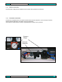
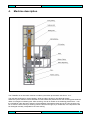
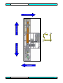
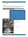
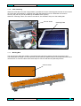
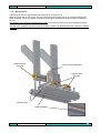
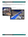
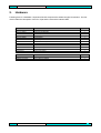
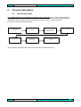
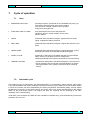
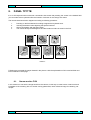
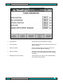
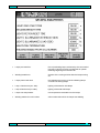
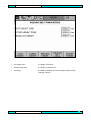
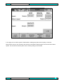
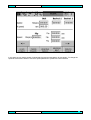
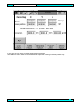
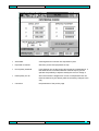
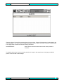
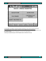
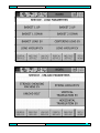
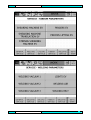
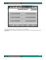
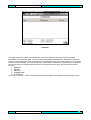
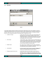
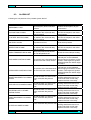
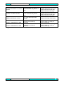
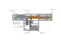
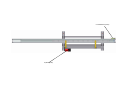
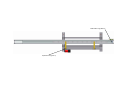
User manual
User Manual
November 2007
Project
TS600 IRA
2BG s.r.l.
18, Monte Bianco street
ZIP 35018 – San Martino di Lupari (PD) ITALY
2BG s.n.c.
1-1
User manual
1.
1.1.
Introduction
1-3
Presentation ................................................................................................................................... 1-3
2.
Warranty
2-4
3.
Transport and Installation
3-5
3.1. Transport ........................................................................................................................................ 3-5
3.2. Installation ...................................................................................................................................... 3-5
3.2.1.
Locating and levelling ............................................................................................................ 3-6
3.2.2.
Elettric Connection ................................................................................................................. 3-7
3.2.3.
Pneumatic Connection ........................................................................................................... 3-7
4.
Machine description
4-8
4.1. Structure ....................................................................................................................................... 4-10
4.1.1.
Flux tank ................................................................................................................................ 4-10
4.1.2.
Ribbon Cutter ........................................................................................................................ 4-11
4.1.3.
Ribbon Rail ............................................................................................................................ 4-12
4.1.4.
Load Ribbon .......................................................................................................................... 4-13
4.1.5.
Baskets Movement and Basket Charge.............................................................................. 4-14
4.1.6.
Cells Centering...................................................................................................................... 4-15
4.1.7.
Welding Belt .......................................................................................................................... 4-15
4.1.8.
Welding Zone ........................................................................................................................ 4-16
4.2. Hardware....................................................................................................................................... 5-18
5.
Process Description
6-19
5.1. General description ..................................................................................................................... 6-19
5.2. Soldering operation cycle ........................................................... Errore. Il segnalibro non è definito.
5.2.1.
Uses........................................................................................................................................ 7-20
5.2.2.
Automatic cycle .................................................................................................................... 7-20
5.3. PANEL TP177B............................................................................................................................. 8-21
5.3.1.
Recipes .................................................................................................................................. 8-40
5.4. ALARM LIST ................................................................................................................................. 8-41
2BG s.n.c.
1-2
User manual
1.
Introduction
1.1.
Presentation
This manual purpose is to introduce you all the components of the system that form the “TS600 IRA” for the
soldering of photovoltaic cells and respective functions. The intention is to furnish a manual that is a valid
help for the operator, to understand the exact operation of the various processes, and for maintenance
personnel, to assure an exhaustive support to understand the system automation.
The manual first part describes the machine operation process; then a second part where is describing the
working process following the management interface (HMI, Human Machine Interface) through which the
operator can plan and monitoring the machine operation. The fourth part of the manual explain the recipes
database architecture: the recipe filing and the loading functions are illustrated. The fifth part of the manual is
reserved to the alarms description managed by the PLC and the correct procedures to acknowledge and fix
its.
Don’t observe of the follow instructions in this manual or the wrong use of the machine means to cancel
ts600 warranty
Check when the machine will arrive the conditions; if is not happen give to Penergy a written communication
not later than 4 days. To repair, corrections or modifications is necessary to communicate this to
manufacturer
Don’t remove the machine safety barrier! ; this could be dangerous for the operators
2BG s.n.c.
1-3
User manual
2.
Warranty
The good quality of the material to build the machine is guaranteed
The length of the warranty is of 12 months. Are not covered bad working caused from inexperience,
employment mistake, bad maintenance or consumable part wear and tear.
Faulty parts will be changed in place from licenced technicians. Trip, food and accommodation will be
charged to the costumer.
Expenditure to change damaged parts for a bad use of the machine will be charge forward like the
expenditure for the trip, food and accommodation of the technicians
The consumable parts ARE NOT inside the warranty.
Important: the estimate of damaged parts to change or to repair will be supervised from qualified and
authorized technicians to set out the problem sort and possible warranty change
It will be a costumer task to check the machine as soon as arrived to estimate every damages for the
transport. If there will be this problem, the costumer will have to give written communication not lather than 4
days. The problem estimation will be debated from the costumer and from transport supplier
THE WARRANTY STOP IF:
•
•
•
•
•
Manual instructions are not respected
There will be modifications without authorization
Programmed maintenance is not followed
The maintenance will be done from not licensed people
The machine will be used from a different purpose from that designed
2BG s.n.c.
2-4
User manual
3.
Transport and Installation
3.1.
Transport
The machine is packed in wood crate with mechanical movement blocked; every pack modification can be
asked at least 1 month before the expected expedition date.
The crate can be moved with a forklift truck or a tackle that are able to support the whole weight of the crate.
To lift or to move the machine with extremely attention avoiding blows that they can damage the
structure.
To arrange before machine arrive the place of installation thinking impediments, escape way, safety
working place to avoid another movement.
3.2.
Installation
At the moment when you decide the working place of the machine , think over the follow shrewdness:
•
•
•
•
•
The working place have to be protected from atmospheric conditions
The working place has not to have a temperature upper 30° and an humidity upper 90%
The floor have to be perfectly flat and support the machine weight
The electric connection have to be done with a cable of right section and support the absorption of
the machine (4x6 mm² with a lenght not over 20 m)
Air connection has to guarantee to the machine a pressure of 7 bar constant
2BG s.n.c.
3-5
User manual
3.2.1.
Locating and levelling
Position kindly the machine over the floor, check that the structure is perfectly horizontal. Adjust the various
height lifting or lowering the tabber stringer feet
Adjustable feet
If you have to move the machine to use a right forklift truck and insinuate the extensioned clamp of the same
length of the machine in the zones pointed in the picture. To pay attention in this procedure because you
can damage some movement of the tabber stringer and so it will not be possible to use it
lifting zone
2BG s.n.c.
lifting zone
3-6
User manual
3.2.2.
Elettric Connection
Check that the voltage is that needed from the machine like pointed in the CE label
3.2.3.
Pneumatic Connection
Connect the compressed air to the machine with a fast connector and with a 10 mm air pipe. Check at
regular intervals that there is not water in the air connections.
The machine is tested and its working is guaranteed at constant 7-8 air pressure
Pressure
Gauge
Pressure
Regulator
2BG s.n.c.
3-7
User manual
4.
Machine description
The TS600IRA is an automatic machine to solder by the ribbon photovoltaic cells from 4” to 6”
The cells are positioned on charge basket , while the ribbon wheels on provided rail wheels.
When the cycle is started a cell is collected from the basket and positioned over the centering plate while the
ribbon is arranged on soldering belt. After centering, the cell is carried on the soldering plate and etc ..until
the celll will be under the lamps where it will be soldered. Reached the fixed amount of cells, the string will
be cut from the other cells by a shearing machine and then brought, by a unload belt, to the flip where it will
be discarged manually o adjusted for the next working
2BG s.n.c.
4-8
User manual
backward
backward
z
+
x
+
+
forward
y
forward
2BG s.n.c.
4-9
User manual
4.1.
4.1.1.
Structure
Flux tank
This tank is filled of flux necessary to solder ribbon over the cells. Is important don’t exceed the maximum
limit to avoid the leakage of the product. The operator has to fill manually this tank when the flux level will
became too low; in this event the machine will give too you an alarm of “flux lacking”
The flux is a product highly inflammables and so is important to touch with with attention and to
wear safety clothes like gloves and protective glasses
Filled Maximum
Level Tank
Knurled Cylinder
Smooth Cylinder
Flux Presence Sensor
2BG s.n.c.
4-10
User manual
4.1.2.
Ribbon Cutter
This part of the machine cut te ribbon through 2 pneumatic cylinder.
There are 2 rails to check the ribbon positioning to direct the ribbon accuracy over the bus bar. The ribbon
then is closed through 2 pneumatic cylinder to keep it still after the cut.
This part have to be cleaned daily from remainig flux left from the vaporization.
Pay attention when you clean this part because there are blunt and sharp parts. We suggest to use
no-cut gloves
Shearing Machine
RibbonLocking
RibbonPostionRegulating
2BG s.n.c.
4-11
User manual
4.1.3.
Ribbon Rail
In this part of the machine the ribbon is directing before the flux tank. There are 2 presence sensors that
signal the breakage or the ribbon ending,.
Ribbon Regolation Guide
Ribbon Presence Sensors
2BG s.n.c.
4-12
User manual
4.1.4.
Load Ribbon
In this zone the ribbon wheels are charged.
Check that wheels movement are free to have a good fluent draught
2BG s.n.c.
4-13
User manual
4.1.5.
Baskets Movement and Basket Charge
There are 2 equal charge units that they have the same function in different time; this to allow to charge a
basket while another is working without to stop the machine
During the cycle the cells are lifted up till the optical fibre or, if there are not cells, till to reach the high extra
running sensor. In this way the basket plate will move to the other side and so will be possible to charge the
cells in the other basket.
When the cells will reach the optical fibre, the movement to direction high is stopped and so will be possible
to take the cell and move it to the centering plate
Extrarunning Sensors
Optical Fibre
2BG s.n.c.
4-14
User manual
4.1.6.
Cells Centering
When the cell is taken from the charge basket, is positioned over the centering plate and the vacuum turned
on to have the cell immobility in centering step. Then the plate will move in 3 dimensions to center in
accuracy way the cell ( this is possible by an OMRON vision system)
When the centering is done, the vacuum is turned off, the cell taken end put on the welding belt
Vacuum Holes
4.1.7.
Centering Plate
Welding Belt
The cells and the ribbon are loaded on the welding belt and kept in position through the vacuum holes.
The welding belt is divided in 3 zones and they can be heat up in different way to avoid thermal shock to the
cell structure. In each zone there are thermocouple to check in real time the plate temperature
Vacuum Holes
zone 3
zone 2
zone 1
2BG s.n.c.
4-15
User manual
4.1.8.
Welding Zone
The welding is done through infrared lamps climbed on a solder pick up.
When the cell arrives on the zone 3, the pick goes down and the lamp turn on for a set time allowing the
ribbon soldering. There are needles climbed on the springs to hold down and flat the ribbon in soldering
process.
Pay attention to the pressure regulation on the cells of this structure because a good regulation means a
good soldering and a good string appearance.
The alignment regulation vertical and horizontal have to be done by qualified technician, because a delicate
operation
Welding Position
Regulator
Lamps Pressure Regulator
Lamps Position
Regulator
Infrared Lamps
Welding Needles
2BG s.n.c.
4-16
User manual
4.1.9.
Unload Zone
Reached the set welding cells number, the shearing machine divides the string from the next one.
Then the string is dragged out from the unloading belt to intake point. The flip lean on the string , the vacuum
is turned on and kept to unload position
Shearing Machine
ExtraRunning Sensor
Flip
2BG s.n.c.
4-17
User manual
5.
Hardware
Following there is a hardware components list that composes the “tabber stringher” automation. The first
chart includes the description of the PLC Vipa and the second the interface HMI.
Codice Prodotto
VIPA 215-2CM02
CPU 215 CAN
VIPA 221-1BH10
VIPA 222-1BH10
VIPA 232-1BD51
VIPA 240-1BA00
VIPA 208-1DP01
OMRON F500
Digital Input DI16xDC24V
Digital Output DO16xDC24V 1A
Analog Output AO4x12Bit
Serial Interface
Profibus Dp Master
Omron F500 Vision System
1
3
1
SMC 51EXP2
MURR 56501
MURR 56622
MURR 56623
MURR 56478
GateWay Unit EX500 Series SMC
Bus Node
Digital Input Module
Digital Input Module
Analog Input Module
1
1
3
2
1
Codice Prodotto
6AV6 545-OBB15-2AX0
OMRON F150-M05L.
Descrizione
touchscreen Panel SIEMENS TP170
Camera Monitor OMRON
2BG s.n.c.
Descrizione
Quantità
1
1
1
1
Quantità
1
1
5-18
User manual
6.
Process Description
6.1.
General description
The “Tabber Stringher” is a machine managed by an only operator (for the safety of the personnel
himself) that, through a cycle pre-planned, solders, connecting in series, the cells in the loading baskets,
unloading the string on a flip axis, when reached the number of cells for string pre-planned.
In picture 1 the process phases are show.
CELLS AND RIBBON
LOADING
SOLDERING
PRESTART VALUES
ATTAINMENT
UNLOADING ON
CONVEYOR
CELLS LOADING
FROM BASKETS
CELL CENTERING
TRASLATION OF THE
STRING
All the operation parameters are stored in recipes in the line supervision panel.
2BG s.n.c.
6-19
User manual
7.
Cycle of operation
7.1.
Uses
•
EMERGENCY BUTTON:
pressing this button, positioned on the TS300IRA side pulpit, you
interrupt the electrical power of the electric cabinet
uses, because a danger condition for the operator
during the working process.
•
AUXILIARY CIRCUIT LAMP:
lamp positioned on the front of the pulpit that
signals the power to all the auxiliary circuits of the
electric cabinet.
•
SIREN:
positioned above the tabber stringher, signals with an acoustic
signal, it signals the alarms presence.
•
RED LAMP:
positioned above the tabber stringher it signals the presence of an
alarm.
•
GREEN LAMP:
positioned above the tabber stringher it signals automatic cycle to
fixed light and values of prestart reached to flashing light.
•
PANEL TP177B:
positioned on side pulpit of the tabber stringher it is the interface
HMI in which you can planned and to modify all the
soldering parameters and manual commands for machine testing.
•
OMRON F150 M05L
positioned on side pulpit of the tabber stringher it is the monitor of
the two cameras. We can see the actual visualization of camera
switching between cam1 (quality control) and cam2 (centering
control)
7.2.
Automatic cycle
The soldering cycle, as mentioned in the general description, is composed by various phases: cells loading
in the special baskets and ribbon introduction through the centering rolls; attainment of the pre-start values,
in which the machine, will reach automatically the values pre-planned, automatically telling, through special
signalling the conclusion of the phase; search axis origin; start cycle, phase activated through the special
button on the panel during which it will happen the load, the centering and the soldering of the cells;
unloading of the complete string.
Under start cycle conditions the TS600 Ira, after unloaded a complete string, it will automatically continue the
production of a new one.
2BG s.n.c.
7-20
User manual
8.
PANEL TP177B
It is a LCD keyboard with touchscreen commands: that means that pressing the screen in the desired field
you can make various operations like the insertion of a button or the change of a datum.
The numeric data introduction happens according to following procedure:
1.
2.
3.
4.
Pressing on the field desired for making to appear the keyboard touch.
Inserting the desired value digitizing the special numbers.
Giving confirmation with the enter button.
The numerical keyboard disappears and the introduced value is stored in the PLC.
ON LINE
PARAMETERS
SERVICE
PASSWORD
ALARMS
RECIPE
ACKNOWLEDGE
Picture 2
Following are proposed the pages showed in the picture 2 with the explanations of all numerical fields and
texts contained in each page.
8.1.
Omron monitor F150
In this monitor we can see the image send from the camera, in this way we cane have a visual check and
immediate of the centering. We can set the running parameters, catch reference image for centering, set
recipes
2BG s.n.c.
8-21
User manual
8.2.
Control pages
The page “HOME” it is the start page of the keyboard. All the pages have in common the superior part of the
screen, where are situated: the buttons to access the various submenu of laminator management, the
operation mode “WORK” or “SERVICE”, current date and time; this to give an easy and practical
understanding of the various commands.
2BG s.n.c.
8-22
User manual
The first page “ONLINE” contain part of the values with which the tabber stringher is working: the set values
and measured values of the centering and soldering plates temperatures and a counter for soldered cells:
you can access to it pressing the key “ONLINE” as shown in picture 2. In it the operator can see the process
values, can turn on the pre-start cycle through the special button visualized in picture, to start the axes
search origin and to start the automatic cycle.
•
Pre-start
:
Pressing this button the TS300IRA starts heating the centering and
soldering plates, up to the temperature setpoint attainment.
•
Origin search
:
with this command, after having started the Pre-start, it performs an
axes position calibration, for a correct positioning during the
automatic cycle
•
Start:
With this button it start the real automatic cycle of the machine, that
goes from the basket cells loading, to the complete string unload on
the control glass .
•
Plates Temperature:
In this area there are the temperature regulation data of the
soldering (right part) plates.
•
Lightening time:
In this field you can plan the time during which there are power on
infrared lamps during the automatic soldering cycle.
•
Ribbon cutting:
pushing this button you can make the ribbon first heading
•
Lamp temperature:
Field in which the current temperature of the lamp is show.
•
Cells counter:
In this field you can see the number of the cell loaded on the welding
belt from the latest start
2BG s.n.c.
8-23
User manual
The second page “ONLINE” contain four areas each of them related to a phase of string production.
In the area related to the RIBBON operator has the possibility to visualize the position of ribbon deposit on
the soldering plate and to manually modify the length of ribbon cutting.
In the cells panel it is possible to plan the cell size, the interleave between cells and the number of cells that
form the final string.
In the field lowest quality cell is possible to set the threshold for the waste cells
In the page inferior area, there are the settings for the number of first cells and the different lightening time to
apply to them.
The counter shows the total amount of cells done. The only way to reset this counter is push the lower
button.
2BG s.n.c.
8-24
User manual
the third page online contain the display of the set temperature and the real temperature of the three zone of
the welding belt.
We can see the set temperature and the real temperature of the welding lamps
Lamps off button allow you to exclude the lamps flashing. This is very useful in test mode becasuse we can
see the complete cycle without welding cells
2BG s.n.c.
8-25
User manual
The first page “Parameters” contain all the values to give correct timings and functionality to all the
mechanical and electrical parts: you can access to this page pressing the key “Parameters” as shown in
picture 2. The change of these values must be changed only by competent technical personnel. All the
values inside it can simply be modified pressing with a finger the interested field, to digitize the new value on
the keyboard appeared in popup and to confirm with the “enter” button. The inserted data will instantly be
transferred to the machine. The modifiable fields are following described:
•
General alarm waiting time:
this field is the time in seconds to filter all the generic
alarms, after this time alarms will be signalled.
•
EV alarm waiting time:
this field is the time in seconds to filter the EV
related alarms, after this time alarms will be
signalled.
•
Load cells basket blowing time:
duration of the air blowing impulse on the load
baskets, the electrovalve opens on the descent of
the load cells cilynder and closes after the planned
time; the air blowing has the function to divide the
cells during the loading operation
•
Unload traslator distance from string cut:
distance between string cut and the middle of unload
translator
•
String unload vacuum time:
time during which the load axis wait the vacuum
making on the first present cell in the basket before
to load it on the centering plate; this to guarantee
that there are enough vacuum in the load suckers to
lift the cell
•
Vision system recipe numbers:
recipe number set through vision system
2BG s.n.c.
8-26
User manual
•
Home position:
start position of the pliers after zero setting
•
Pick up position:
position that the pliers axis reaches in the moment of
ribbon collecting
•
Advance position:
Pick up: position that the unload axis reaches for
to pick up the cells after the soldering
•
Delta out position:
position which the pliers axis reaches after unload
the ribbon on the cells prepared above the soldering
of welding.
•
Raising piston reset measure
vertical position of the pliers, after unloaded ribbon
and moved to home position
2BG s.n.c.
8-27
User manual
•
Lamps pre-start time:
time of preheating lamps, activated by the command of
pre-start; it has the function to guarantee an optimal
soldering beginning from the first cell.
•
Welding breath time:
duration of the cooling air blow after the lamps turning
off.
•
Lamps piston reset time:
time between the turning off of the soldering lamps
command of leaving lamps.
•
Lamp 1 illuminance (ext. side):
lighting of the exterior side lamps
•
Lamp 2 illuminance (int. side):
lighting of the load side lamps
•
Lamps max temperature:
max temperature reachable from the lamps
•
Welding enable from cell number
cells number after which the lamps start welding
2BG s.n.c.
8-28
User manual
•
First lenght zone:
the lenght of first zone
•
Second lenght zone:
the lenght of second zone
•
Cut lenght:
the distance between the first cell depot and the strings
shearing machine
2BG s.n.c.
8-29
User manual
In this page we can set the speed of load traslator, welding belt, pliers and the quality control tool
Pliers have 2 velocity, one of di this is the velocity of the ribbon hauling that we can set in the field "ribbon
speed". For the other movement pliers use the velocity setting in the first field
2BG s.n.c.
8-30
User manual
In this page we can set the speed of unload belt, first and second basket, flip movement. To change the
speed of unload belt is better to use the k speed parameter to preserve the sincronization
2BG s.n.c.
8-31
User manual
In this page we can set the centering speed and home position.
We can also to add an offset to the coordination to adjust the centering in the best possible way
2BG s.n.c.
8-32
User manual
•
Serial data:
centering data from second cam expressed in pixel
•
Expected movement:
data from previus field (expressed in step
•
No ok quality threshold
in this field we can set the lowest cell percentual correspondence. If
this threshold isn’t oversubscribed the machine stop to give the
operator the possibility to adjust manually the cell or to change it
•
Reset quality non ok
when the machine is stopped to a too low correspondence we can
reset the machine by this button (after the necessary changes to the
cell)
•
Correction:
the parameters of the previus page
2BG s.n.c.
8-33
User manual
The page “Alarms” show all the present alarms in the machine. These will subsequently be described in the
alarm paragraph. You can access this page pressing the button “alarms” as shown in picture 2. Additionally
to this page there are also two buttons following described:
ALARMS RESET:
Button which cancel the alarms that are not more presents in
machine.
To quiet the alarm siren, there is a button placed on the right in the superior bar of the page, suitable in
picture 2 with the label “acknowledge"
2BG s.n.c.
8-34
User manual
In these pages it is possible to modify the operation parameters of the machine motorized movements.
The change of these values must be changed only by competent technical personnel.
These commands are enable only with the machine in manual mode. To activate this state you have to push
the "man/aut" button.
The manual commands have not stoppage so you have to pay great attention.
Following the detailed description of the modifiable fields to activate the command
2BG s.n.c.
8-35
User manual
2BG s.n.c.
8-36
User manual
2BG s.n.c.
8-37
User manual
In this page there are buttons to move in 3 dimension the centering plate.
Is very usefull when you exceed an extrarunning sensor and you want came in the working range before the
origin search
2BG s.n.c.
8-38
User manual
PASSWORD
The page “Password” contain the management of all the accesses to the various menù and change
parameters of the operative panel. You can access to thios page pressing the key “Password” as shown in
picture 2. The management of the qualifications to the various functions is by levels: a high level correspond
to more accesses operator can have. As in picture “Administration Password” the parameters to be inserted
are: the username, the relative password and the corresponding access level. The levels are described
following:
1. MANUALS
2. ONLINE
3. RECIPES
4. PARAMETERS
5. PASSWORD
The button “LOG OUT” set the access level to zero and visualizes in the operative panel the page “Home”
2BG s.n.c.
8-39
User manual
8.2.1.
Recipes
RECIPE
In the page “Recipes” operator introduces all the inherent parameters to the cycle of operation, so that to
create a file to transmit to the PLC in a second moment. In this management are created and stored all the
set-point values which serve for the production of all the different types of strings. In the figure “Recipes”
there are some management buttons, its are described here departing from left:
•
Create new recipe:
pressing this button all the values in the central window are
reset and a new “set of data” is created, a name can be
assigned pressing the corresponding field (Name set of data),
inserting the desired name using the keyboard that appears
and pressing “enter” when finished.
•
Save recipe:
with this button, after created a new set of data,assigned him
a name and modified the relative parameters , it is possible to
save the recipe in the internal memory of the operative panel.
The recipe will subsequently be open selecting the relative
name of the set of data in the specific field.
•
Delete recipe:
this is the function to delete the current recipe visualized in
the operative panel. This operation is permanent and then we
recommend the maximum attention doing that.
•
Transmission
recipes to the PLC:with this button the panel transmits to the
PLC the current recipe. From this moment the visualized
values go to overwrite those in the PLC memory
•
Reading recipes from the PLC:
pressing this button the panel read the current values of
operation in the PLC memory and it visualizes them in the
chart; here you can modified and saved inserting a new name
in the field “name set of data” and pressing the button “salute
recipe”
2BG s.n.c.
8-40
User manual
8.3.
ALARM LIST
Following the complete list of the possible system alarms:
ALARM
POSSIBLE CAUSE
RESTORATION
The emergency button has been
pressed.
Restore the emergency to give
back tension.
The consumption of the motor is
too raised or the command relay
doesn't respond.
The consumption of the motor is
too raised or the command relay
doesn't respond.
Verify if there are short-circuits and
the real consumption; then reset
the protection.
Verify if there are short-circuits and
the real consumption; then reset
the protection.
AIR LEVEL ALARM
Air pressure too low
Chek the air pressure
WATER PUMP ALARM
The consumption of the motor is
too raised or the command relay
doesn't respond
Verify if there are short-circuits and
the real consumption; then reset
the protection.
LAMPS TEMPERATURE ALARM
Lamps temperature has passed
the max temperature set
Check the correct lamps working
EMERGENCY STOP
VACUUM PUMP ALARM
FLUX REEL MOTOR ALARM
LOAD AXES POSITION ALARM
PLIERS AXES POSITION ALARM
The position of the interested axes
has overcome the overrun switch.
The position of the interested axes
has overcome the overrun switch.
The electrovalve is in short-circuit
BASKET MOVEMENT CYLINDER
or the command relay doesn't
ALARM
work.
Turn off the principal cabinet and
manually act on the interested
axes bringing it toward the central
position. Close again the general
switch and start the “Search origin”
procedure.
Turn off the main cabinet and
manually act on the interested
axes bringing it toward the central
position. Close again the general
switch and start the “Search origin”
procedure.
Verify that the electrovalve is
working and that the fuse is not
broke. Check the control relay.
Replace the fuse or the relay.
Verify that the electrovalve is
working and that the fuse is not
broke. Check the control relay.
Replace the fuse or the relay.
Verify that the electrovalve is
working and that the fuse is not
broke. Check the control relay.
Replace the fuse or the relay.
Verify that the electrovalve is
working and that the fuse is not
broke. Check the control relay.
Replace the fuse or the relay.
LOAD CELLS CYLINDER ALARM
The electrovalve is in short-circuit
or the command relay doesn't
work.
CENTERING CELLS STORE
PISTON ALARM
The electrovalve is in short-circuit
or the command relay doesn't
work.
LAMPS MOVEMENT CYLINDER
ALARM
The electrovalve is in short-circuit
or the command relay doesn't
work.
CUTTER CYLINDER ALARM
The electrovalve is in short-circuit
Verify that the electrovalve is
or the command relay doesn't work
working and that the fuse is not
broke. Check the control relay.
Replace the fuse or the relay.
.
2BG s.n.c.
8-41
User manual
The electrovalve is in short-circuit
CUTTER MOVEMENT CYLINDER
or the command relay doesn't
ALARM
work.
Verify that the electrovalve is
working and that the fuse is not
broke. Check the control relay.
Replace the fuse or the relay.
Verify that the electrovalve is
working and that the fuse is not
broke. Check the control relay.
Replace the fuse or the relay.
STRING CYLINDER ALARM
The electrovalve is in short-circuit
or the command relay doesn't
work.
RIBBON PRESENCE ALARM
One of the ribbon spools are
finished
Replace the empty ribbon spool.
The interested basket is not
present it is not correctly
positioned
The interested basket is not
present it is not correctly
positioned
To insert the basket of loading in
its own center or to verify its
correct positioning.
To insert the basket of loading in
its own center or to verify its
correct positioning
BASKET 1 PRESENCE ALARM
BASKET 2 PRESENCE ALARM
•
2BG s.n.c.
8-42
Welding Belt Motor(18M1)
Pliers Axis Motor(19M1)
Charge Axis Motor(17M1)
Centering Motor X (21M1)
Centering Motor Y (21M2)
Centering Motor Z (21M3)
Basket Charge Motors(24M1)
Basket1 Motor(15M1)
Basket2 Motor(16M1)
UnloadBeltMotors(20M1)
FlipMotor(23M1)
BeltExtraRunning(49BFC2)
FlipExtraRunning(23FC1)
Ribbon Dx Presence (45FC1)
Ribbon Sx Presence (45FC2)
Backward ShearingMachine (44FC3)
Forward ShearingMachine (44FC2)
Open ShearingMachine
(44FC1)
Pliers ExtraRunning (19FC1)
Charge ExtraRunning (17FC2)
Charge ExtraRunning (17FC1)
LampsSet Down(43FC1)
LampsSet Up
(43FC2)
StringShearingMachine(46FC1)
Pressostato (16P1)
Pliers ExtraRunning 2(19FC2)
Charge from Low Centering (41FC4)
Charge from High Centering (41FC3)
Flux Sensors(49BFC3)
Centering Home Asse X
(22FC6)
Centering Extra running Axis X (22FC3)
Centering Home Axis Z
(22FC4)
Centering Extra running Axis Z (22FC5)
Centering Home Axis Y
(22FC1)
Centering Extra running Axis Y (22FC2)
String Sensor(49BFC1)
Charge from Basket Low (41FC1)
Charge from Basket High (41FC2)
Basket Presence2 (40FC4)
Basket Presence 1 (40FC3)
Basket Position 2 (40FC2)
Basket Position 1 (40FC1)
Basket 1 Low (15FC2)
Basket 1 High (15FC1)
Basket 2 Low (16FC2)
Basket 2 High (16FC1)
Optical Fiber Cells Presence(15FO1)