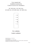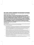
1
User manual and
installation instruction
Control Unit for Fire Ventilation
RV 24V-5A / RV 24V-24A / RV 24V-32A
RV 48V-5A / RV 48V-24A / RV 48V-32A
Fire ventilation
Comfort ventilation
24VDC/48VDC max. 5A/24A/32A
2 actuator outputs
1 fire ventilation group, 2 comfort groups
Connection for fire switches, wind- and rain sensor, comfort switches, smoke detectors
Possibility for bus connection of 10 RV control units
#211680
Control for Fire and Comfort ventilation Type RV 24V-5A/RV 24V-24A/RV 24V-32A / RV 48V-5A/RV 48V-24A/RV 48V-32A
Control for Fire and Comfort ventilation Type RV 24V-5A/RV 24V-24A/RV 24V-32A / RV 48V-5A/RV 48V-24A/RV 48V-32A
Address of installation
Table of contents
Name:
___________________________________________________________________________________________
Address of installation / Description of installation ........................................................................................ 2
General description .......................................................................................................................................... 4
Safety rules during installation and operation ................................................................................................. 5
Explosion danger.............................................................................................................................................. 5
Installation........................................................................................................................................................ 5
Yearly legal requirement of maintenance and control ..................................................................................... 5
Connection to motor- (actuator) outputs and line monitoring ......................................................................... 6
Current limiter type LIP. .................................................................................................................................. 7
Operation and connection of fire switches....................................................................................................... 8
Connection of smoke-/heat detectors............................................................................................................... 9
Comfort ventilation - Connection and settings ................................................................................................ 9
Diagramme RV control unit and connections ............................................................................................. 10-11
External LEDs on the front panel (LED board)............................................................................................... 12
Internal LED indication on the main board ..................................................................................................... 12
Fuse specifications ........................................................................................................................................... 12
Complete jumper settings ................................................................................................................................ 13
Connection of more RV control units to one fire group (bus connection) ....................................................... 14
Connection of weather sensor / Close all function .......................................................................................... 15
External signal transfer, connection of AFA systems and other control systems............................................. 15
Special functions.............................................................................................................................................. 16
Cable sizes ....................................................................................................................................................... 16-17
Part nos. and accessories.................................................................................................................................. 18
CE Declaration of conformity.......................................................................................................................... 19
Technical specifications ................................................................................................................................... 20
Address:
___________________________________________________________________________________________
Phone no.:
___________________________________________________________________________________________
Contact person:
___________________________________________________________________________________________
Date of installation:
___________________________________________________________________________________________
Installation
Number of RV control units and type (ex. RV 24V-24A):
___________________________________________________________________________________________________
Number of fire ventilation groups:
___________________________________________________________________________________________________
Type of opening system:
___________________________________________________________________________________________________
Valid from board A042 V8.3 valid from software version XXX
Type of opening system:
___________________________________________________________________________________________________
Rev 0.03 19-01-2011
Type of opening system:
___________________________________________________________________________________________________
External controls (AFA-CCS):
___________________________________________________________________________________________________
Comfort control:
___________________________________________________________________________________________________
Wind- and rain sensor:
___________________________________________________________________________________________________
220V power supply from group:
___________________________________________________________________________________________________
2
Manufacturer:
Actulux A/S
Haadvaerkervej 2
DK 9560 Hadsund
Danmark
Tel.: +45 98 57 40 90
Fax: +45 96 15 28 00
e-mail: [email protected]
www.actulux.com
3
Control for Fire and Comfort ventilation Type RV 24V-5A/RV 24V-24A/RV 24V-32A / RV 48V-5A/RV 48V-24A/RV 48V-32A
Control for Fire and Comfort ventilation Type RV 24V-5A/RV 24V-24A/RV 24V-32A / RV 48V-5A/RV 48V-24A/RV 48V-32A
General description
Safety rules during installation and operation
The RV control unit can be used for electrical opening of e.g. skylights, smoke hatches or similar in connection
with fire- and comfort ventilation.
The RV control unit has different inputs with line monitoring which can be activated by e.g. fire switches, smoke
detectors, heat detectors, AFA systems and CCS systems.
For control of the indoor climate (comfort ventilation) manual switches, weekly timer, room thermostat and
outdoor weather sensors can be connected.
By means of LEDs in the the front panel the control indicates the operating condition (ok operation and
error- and alarm condition), just as it by means of the built-in potential free relay contacts can re-lay operating
information about ok operation and error- and alarm condition to other systems in the building.
The RV control unit may only be installed and maintained by personnel authorized for installation of automatic
electrical fire ventilation equipment.
The RV control unit is a part of a range of control units which are all built with a AC main supply and with either
24 or 48 volts DC motor supply. The range consists of the following types:
RV 24V-5A, RV 24V-24A, RV 24V-32A:
24 volts DC motor supply, power capacity 5A, 24A and 32A respectively.
RV 48V-5A, RV 48V-24A, RV 48V-32A:
48 volts DC motor supply, power capapity 5A, 24A and 32A respectively.
The polarity of the motor supply is reversed when opening or closing.
The RV control unit has built-in 72 hours battery back-up.
By a unique bus system consisting of a 3 wire cable the RV control units can be mutually connected so that up to
10 RV control units can be connected and operate as an integrated system.
Connection of cables to the in- and outputs of the RV control unit is described in the connection drawing on
page 10-11.
A more detailled connection to the individual in- and outputs is described in the individual sections in this
manual.
Selection of cable sizes on page 16.
By means of jumpers the RV control unit has different setting possibilities for in- and outputs. These settings are
indicated in a complete table (please see section with jumper settings on page 12-13).
Examples of types of openings systems and the max. power consumption which can be connected to the
RV control unit:
Type:
SA Power Single
SA Power Double
SA Power Large
Rotary 100
RA Light
Others
24V power supply:
48V power supply:
4A
2A
8A (2x4A)
4A (2x2A)
8A
4A
2,5A
1,25A
2,5A
1,25A
See specification of max. power consumption on the opening system
Explosion danger
The RV control unit is supplied with back-up batteries, which contain large amounts of energy which can be
released as explosion in case of wrong handling - the following safety rules must therefore always be observed:
• Νever short-circuit a back-up battery.
• Do not use external chargers on installed batteries. If unauthorized chargers are used explosive gasses
can be released from the battery.
• Do not drop back-up batteries as strong acids can be released if they are broken.
Installation
The RV control unit can weigh up to 25 kgs and must be installed on a stable wall. Use either the pre-mounted
flanges mounted on the backside of the cabinet or remove the flanges, and 6 mm screws can then be mounted
through the steel bottom plate of the RV control unit, further through the plastic cabinet into the wall.The last
mentioned way of installation may require that the batteries are dismantled in order to get access to the screw
holes.
All cables are connected according to the drawing on the central pages and are dimensioned according to table
page 16. Keep in mind that the operating voltage from the RV control unit is either 24V or 48V and that the max.
voltage drop is 15% which demands correct cable dimension.
Please be aware that it often may be required (in order to keep the demands on the CE marking of the complete
installation or another law) that the RV control unit is supplied with 230V AC from separate powerline with its
own ground error circuit interrupter, and that a repair interrupter is mounted on the motor lines.
After connection the RV control unit must charge the batteries min. 12 hours before complete testing.
Yearly legal requirement of maintenance and control (authorized)
The functions of the RV control unit and the opening system must be tested by authorized personnel at least
once a year. The RV control unit informs when the maintenance should be done. The external LEDs on the front
panel flashes fast. The RV control unit and opening system are of course still full operating. Please call a service
technician at your earliest convenience in order to carry out the maintenance and to test the control and opening
system, in order to prepare it for another year of operation. The legal requirements for this must be observed and
the testing and control must as a minimum include the following:
• Control that all opening systems move to full opening when the fire function is activated - should not
be carried out if the wind is more than 6 m/sec. as there might be a risk that the opening system cannot
close automatically.
• Control of the batteries. If the batteries are replaced it is important to use the same type as the batteries
are carefully chosen to be able to deliver the current, for which the control is specified.
• Control of in- and outputs on the control.
• Control of fire switches and smoke- and heat detectors.
The batteries should be replaced as required, however at least every third year!
4
5
Control for Fire and Comfort ventilation Type RV 24V-5A/RV 24V-24A/RV 24V-32A / RV 48V-5A/RV 48V-24A/RV 48V-32A
Connection to motor- (actuator-) outputs and line monitoring
The actuators (motors) must be connected to one of the 2 actuator outputs on the output terminals 2-3 or 4-5.
It is possible to connect and disconnect the line monitoring on the 2 actuator outputs (the factory setting is
“connected”). The cables to the actuators can be connected in series or parallel or a combination of these (please
see drawing with examples or connection diagramme on the central pages).
It is important to keep the right polarity of the cables - The actuators must always be connected through a current
limiter, e.g. the Actulux LIP or similar.
Cable monitoring (line monitoring) on the motor outputs
The control is equipped with 3 possible settings for cable
monitoring (line monitoring), which can be configured by
means of jumper J7 (actuator output 1) and jumper J9
(actuator output 2).
Jumper J7 and J9 is mounted in pos. »Motor line«
Line monitoring between terminal 2-3 and 4-5.
The jumpers J4 (actuator output 1) and J5 (actuator
output 2) are set according to the number of
termination resistors (27KΩ ) to be detected – for
each actuator output 1 to max. 6 lines can be detected
by moving the jumpers J4 and J5 respectively – this
means that the cable installation between the RV
control units and the actuators can be established in
series connection (cable connection from e.g. skylight
1, further to skylight 2, etc.), or parallel connection
(cable connection from each skylight to the control),
or a combination of these. However, as mentioned
max. 6 different lines can be detected each terminated
with a 27KΩ resistor.
For RV 24V-5A/RV 48V-5A the max. allowed
current is 5A, e.g. 1 x 5A or 2 x 2.5A.
Control for Fire and Comfort ventilation Type RV 24V-5A/RV 24V-24A/RV 24V-32A / RV 48V-5A/RV 48V-24A/RV 48V-32A
Jumper J7 and J9 mounted in pos. »Ext 3 wire«.
Line monitoring between terminal 1-3 and 5-6:
With the jumpers J4 (actuator output 1) and J5
(actuator output 2) it is chosen, how many lines (number of
27KΩ ) you wish to detect - the same way as the motor line.
This setting demands 3 wire cable from motor output to
motor.
Jumper J7/J4 and J9/J5 are not mounted - No line
monitoring for actuator output 1 and actuator output 2
respectively.
For RV 24V-5A/RV 48V-5A the max. allowed current is
5A, e.g. 1 x 5A or 2 x 2.5A.
Current limiter type LIP function and setting (if mounted)
The current limiter type LIP (mounted on the opening system) is used as current limiter between the 48/24V DC
supply and 1 or 2 actuators. When the adjusted current limit is reached, the speed of the actuators is reduced.
When the max. power on the actuator is exceeded, the actuator stops. On the 24V/48V types (LIP5 or LIP6) max.
5 times overload cut outs in the same direction is allowed. After that it will not be possible to run in this direction
again, before the motor has run in the opposite direction. This in order to protect the actuator gear mechanism.
Please note that when opening, the red LED in the LIP must light. This indicates that polarity to actuator is
correct.
Table of LIP settings
Opening system
DIP 1
DIP 2
Jumper description
J4
Number of connected 27Kohm termination resistors for
actuator output 1
Type
J5
Number of connected 27Kohm termination resistors for
actuator output 2
J7
Chooses line monitoring through motor terminals 2-3 and
4-5 (Mot Mon) or separate wire terminals 1-3 and 5-6 (Ext Li
Mon), or no line monitoring when J7/J4 or J9/J5 is removed.
J9
F3
Fuse 15A (blue) for actuator output 1
24A+32A control units
F4
Fuse 15A (blue) for actuator output 2
24A+32A control units
F3
Fuse 5A (light brown) for actuator output 1 / 5A control unit
F4
Fuse 5A (light brown) for actuator output 2 / 5A control unit
Not used
OFF
OFF
3A SA Power
ON
OFF
Board
description
A028
Voltage and
function
24 V 2 channels
DIP 1 DIP2
LIP3
Part no.
board
111305
LIP4
111315
A036
24 V 1 channel
See diagram
above
LIP3
111330
A040
LIP5
121315
LIP6 *
121330
4A SA Power
OFF
ON
2,5 A Rotary 100
ON
ON
DIP3 DIP4 DIP5
DIP6
DIP7
DIP8
OFF
ON
27K
ON
Test
OFF
27k
ON
test
OFF
M1-M2
OFF
delay =ON
Not mounted
24V 2 channels
OFF
ON
27K
ON
Test
OFF
A043
24/48V 1 channel
A044
24/48V
2 channels
27K
ON
OFF
M1-M2
OFF
delay =ON
Not mounted
ON
27K
ON
M1-M2
delay =ON
Not mounted
* SA Power Large - parallel operation: Jumper OPT mounted - both motors stop at the same time if one stops
because of overload.
6
7
Control for Fire and Comfort ventilation Type RV 24V-5A/RV 24V-24A/RV 24V-32A / RV 48V-5A/RV 48V-24A/RV 48V-32A
Control for Fire and Comfort ventilation Type RV 24V-5A/RV 24V-24A/RV 24V-32A / RV 48V-5A/RV 48V-24A/RV 48V-32A
Operation and connection of fire switches (e.g. type WSK 320)
Connection of smoke-/heat detectors
The fire switch will generally contain the following:
• Breakable glass window and red control button is activated by pressure
- this puts the RV control unit in ALARM condition, by which both
motor outputs are activated (for normal service and testing the lid can be
opened with a key).
• RESET button which brings the RV control unit out of the alarm
condition and starts the closing sequence for about 60 seconds. Please
note that RESET does not cancel errors on the system, e.g. line errors etc.
These must be found and corrected.
• RED LED indicates that the RV control unit is in ALARM condition and
that the motor outputs either are or have been activated.
• YELLOW LED indicates faults on the system - please call for a service
technician.
• GREEN LED indicates that the system is in normal operation condition
without errors.
CONNECTION of the fire switch is made as shown on the drawing.
The installation with fire switches must be terminated with a 10KΩ or 27KΩ
resistor in the last switch in order to establish the line monitoring correctly – this
can either be done by moving the factory mounted resistor from the terminal strip
to the last fire switch or connect jumper J1 in the fire switch type WSK 320 is
mounted (by this a 10KΩ resistor is also connected).
Smoke- and heat detectors are connected as shown.
The installationen can be carried out as 2 loops Dect.1 terminal 19 and 20 and
Dect. 2 terminal 21 and 20 with max. 22 detectors on each circuit.
The last detector in each circuit must be terminated with a 10KΩ termination resistor
so that the cable monitoring (line monitoring) works correctly.
The following settings are possible:
Jumper J16 (Det. 1&2):
Mounted = Min. one detector should be activated in each of the 2 loops in the
installation before the RV control unit goes into alarm condition (this function is
used if the monitored room has potential possibility of limited local occurrences
of smoke/heat in connection with daily use, e.g. because of passage of trucks in the
building).
Not mounted = The RV control unit goes into alarm condition when only one detector
is active, no matter in which of the 2 circuits in the installation the active detector is
placed.
Line monitoring: Correct line monitoring can only be guaranteed with detectors delivered
from the supplier. Other detectors may have different internal resistors and stand by power
consumption.
By means of jumpers the RV control unit has different possibilities of settings for
the input to the fire switch:
Jumper J13 (Conf. firesw.):
Mounted = ALARM condition from 500-3KΩ , (indication of line error by direct
short circuit or open circuit).
Dismounted = ALARM condition from 0-3KΩ (indication of line error by open
circuit).
Jumper J14 (FIRESW. 2 CH):
Mounted = 2 lines, which means that it is possible to connect 2 parallel lines,
each with a number of serial connected fire switches.
Dismounted = 1 line, e.g. by connection of more fire switches, the cables are run
from switch to switch in one line.
Jumper J15 (Failsafe):
Mounted = Any line error on fire switch or smoke detector puts the RV control
unit in ALARM condition. This function can be used if cables to fire switches and
smoke detectors are not fireproof).
Dismounted = An error condition does not report ALARM condition.
WSK 320
green yellow
red
J1
EMERGENCYOPEN
Jumper
”
EMERGENCY-CLOSE
1 2 3 4 5 6 7 8
Signaltransmitter
1 green LED OK (lights when OK and while
closing)
2 yellow LED (lights on error)
3 red LED alarm (emergency opening)
4 ground (-)
5 not used
6 fire switch reset
7 fire switch emergency opening
Jumper J1 must only be set in the last or only
fire switch
8
9
Comfort ventilation – Connection and settings
Each of the 2 motor outputs can be controlled separately with their own comfort switch.
For comfort ventilation there are the following possibilities:
Jumper J17 (Gr. 1 +2):
Mounted = 1 comfort switch controls both outputs.
Jumper J12 (Puls/Const):
Mounted = It is possible to press the »up« button 3 times, which each gives 6 seconds
of opening time at 24V (3 seconds at 48V) – after that nothing happens.
Continuous »up« signal gives 3x6(3) sec.=18(9) sec. - One press on »down« closes the
actuator completely for a period which is 6 seconds longer than the complete opening
time - In order to avoid »actuator pumping« max. 3 successive closing attempts will be
allowed.
Not mounted = As long as »up« signal or »down« signal are given, the actuators are
running.
Jumper J29 (Comf var.)
Mounted = The time on the above mentioned pulse opening can be adjusted from
2-20 sec. on the potentiometre RPT1.
Not mounted = The time on the above mentioned pulse opening is fixed (6 sec. at 24V /
3 sec. at 48V).
Room thermostats, weekly timers, CCS and other external control equipment for comfort
ventilation can be connected on the inputs of the comfort control.
Indication about open or closed actuators:
111685 RV-control position indicator is a relay unit with 2 pcs. DPDT-contacts
230VAC 3A which indicates if the actuators are open or closed. Can only be used
when J12 puls/const is mounted. The function can give information to burglar alarms,
heat controls etc., if the actuators are open or closed.
9
Control for Fire and Comfort ventilation Type RV 24V-5A/RV 24V-24A/RV 24V-32A / RV 48V-5A/RV 48V-24A/RV 48V-32A
10
Control for Fire and Comfort ventilation Type RV 24V-5A/RV 24V-24A/RV 24V-32A / RV 48V-5A/RV 48V-24A/RV 48V-32A
11
Control for Fire and Comfort ventilation Type RV 24V-5A/RV 24V-24A/RV 24V-32A / RV 48V-5A/RV 48V-24A/RV 48V-32A
Control for Fire and Comfort ventilation Type RV 24V-5A/RV 24V-24A/RV 24V-32A / RV 48V-5A/RV 48V-24A/RV 48V-32A
Complete jumper settings (standard setting marked in BOLD)
External LEDs on the front panel (LED board)
Operation possibilities for: Alarm/
fire
Text on front
OK
Colour
Meaning: Switched off - lights - flashes
Green lights if everthing is ok
switched off by local error on this control
flashes by error message from other controls received by bus
Battery low
Yellow
Linie fault
Yellow
AC supply error Yellow
Alarm active
Red
All
lights
lights by local error on this control
flashes by error message from other controls received by bus
lights by local error on this control
flashes by error message from other controls received by bus
lights by local error on this control
flashes by error message from other controls received by bus
lights by local error on this control
flashes by error message from other controls received by bus
time for yearly service - please call for supplier
LD12
Yes
Comfort
operation
Text on board
Factory mounted Mounted function
Dismounted function
J1
Start termination
no
First control on the bus (hardware termination)
All other controls except the first on
bus
Yes
J2
End termination
no
Last control on the bus (hardware termination)
All other controls except the last on
bus
J3
Leds front panel
J4
1-2-3-4-5-6
1
Connect according to number of 27KΩ
termination resistors on actuator 1
No line monitoring channel 1
J5
1-2-3-4-5-6
1
Connect according to number of 27KΩ
termination resistors on actuator 2
No line monitoring channel 2
J6
Programming
J7
Mot Mon act. 1
yes
2 wire line monitoring via 27KΩ terminal 2-3
Ext Li Mon act. 1
no
3 wire line monitoring with direct motor
connection actuator 1
J8
SW10
no
No function
J9
Mot Mon act. 2
yes
2 wire line monitoring via 27KΩ terminal 4-5
Ext Li Mon act. 2
no
3 wire line monitoring with direct motor
connection actuator 2
J10
SW11
yes
J11
Week op
no
Open/close 3-4. sec. every week
No function
J12
PULS/CONS
yes
Actuator runs fixed time each time comfort
switch is activated
6 sec. at 24V / 3 sec. at 48V
Actuator runs as long as comfort
switch is activated
J13
Conf. firesw.
no
Fire switch with series resistors 0,5-3KΩ. short
circuit = line error
Fire switch without series resistors
0-3KΩ. Short cir cuit = alarm
LD13
Yes
LD14
Yes
LD15
Yes
LD16
Yes
Only
close
Only
close
Only
close
No
LD12,
13, 14,
15, 16
Yes
Yes
Internal LED indication on main board
Operation possibilities for: Alarm/fire
LD1
LD2
LD3
LD4
LD5
LD6
LD7
LD8
LD9
LD10
LD11
Actuator 1 open (red). Lights when actuator 1 opens
Actuator 1 close (green). Lights when actuator 1 closes
Actuator 2 open (red). Lights when actuator 2 opens
Actuator 2 close (green). Lights when actuator 2 closes
Weather sensor active (red). Lights when weather sensor is active
Line error on actuator 1 (red). Lights when actuator 1 has line error
Line error on actuator 2 (red). Lights when actuator 2 has line error
Line error on fire switch (red). Lights when fire switch has line error
Line error on smoke detector 1 (red). Lights when smoke detector 1 has line
error
Line error on smoke detector 2 (red). Lights when smoke detector 2 has line
error
BUS error (red). Lights when BUS signal from other controls is missing.
Only relevant if J24 or J25 is mounted.
Yes
Yes
Yes
Yes
Yes
Fuse value
F7
F8 30A green
F9 3A violet
No
Only close
Only close
Only close
Only close
Yes
Only close
Yes
Only close
48V
Not mounted
2 pcs. 12V batteries = 24V
24VDC to terminal 30
- AC supply from 24V power supply
- batt.supp. from the batteries - take care of
discharging of the batteries when 230VAC is
missing
12
To be used for imput of software (authorized personnel)
Comfort
operation
Fuse specifications
Placement 24V
Connection for LED board in front plate
Not mounted
4 pcs. 12V batteries =48V
24VDC to terminal 30
- AC supply from PSU
- batt.supp. from the batteries - take care of
the discharging of the batteries when 230VAC
is missing
No line monitoring channel 1
No line monitoring channel 2
No function
J14
Firesw. 2ch
no
2 parallel fire switch lines
1 fire switch line
J15
Failsafe
no
Line fault on fire switch and smoke detector
put the control in alarm
Standard setting
J16
Detek 1&2
no
Alarm only on concurrent activation of one
detector on each of the 2 lines
Standard setting: Alarm at
armament of any detector.
J17
(Gr. 1+2)
no
One comfort switch controls both actuators.
If J18 bus Comf. is mounted, Comfort Ch2
controls all RV control units on the bus
Actuator output 1 is controlled by
Comfort Ch1
Actuator output 2 is controlled by
Comfort Ch 2
J18
BusComf
no
Comfort Ch 2 controls and is controlled by all
RV control units on the bus
Comfort Ch 1 and Comfort Ch 2
work independent of the bus
J19
SW1
no
Sprinkler function, close when smoke det. is
active
Standard setting
J20
SW2
no
Not used
J21
SW3
no
Not used
J22
SW4
no
70-100°C heat detector can be mounted in each
LIP
J23
SW5
no
Not used
no
First control in the network
J24
J25
no
All other controls in the network
J26
BUZZER1
yes
Acoustic alarm active
Acoustic alarm deactivated
J27
Actu. batt. mode
yes
Actuators are supplies by batteries
Actuators are supplied by 230/24V
converter, batteries as backup
48V controls (4 batteries)
24V controls (2 batteries)
comf. var
no
Comfort pulse adjustable on RPT1
2-20 sec. (24V) /1-10 sec. (48V)
Firm comfort pulse time
6 sec. (24V) / 3 sec. (48V)
J28
J29
13
Control for Fire and Comfort ventilation Type RV 24V-5A/RV 24V-24A/RV 24V-32A / RV 48V-5A/RV 48V-24A/RV 48V-32A
Control for Fire and Comfort ventilation Type RV 24V-5A/RV 24V-24A/RV 24V-32A / RV 48V-5A/RV 48V-24A/RV 48V-32A
Connection of more controls to one fire group (bus connection)
Connection of weather sensor / Close all function
By means of a bus communication it is possible to make 2 – 10 RV control units to work as a complete system.
The RV control units communicate with each other via a 3 wire bus connection. This could e.g. be a 3x0.5 mm²
fireproof cable according to standard IEC 60-31.
A weather sensor can be connected to the RV control unit.
The weather sensor is adjusted according to the instructions.
Actuators should be closed when the wind is above 6 m/s.
LED LD5 on the main board indicate active weather sensor ,lights
as long as input is active.
Terminal no. A1, A2, A3 are for the incoming connection and B1, B2, B3 for the outgoing connection. In the first
RV control unit start Bus J1 has to be on. This control is Master and J24 must therefore also be on. The bus cable
is connected on the output terminals B1, B2, B3 and lead to the next RV control unit which is a slave, J25 must
therefore be on. The cable is connected to the input terminals A1, A2, A3 of the next RV control unit and further to
the next slave RV control unit from terminal B1, B2, B3. In the last slave RV control unit J2 and J25 must be on in
order to terminate the bus connection.
ALARM: Connection of alarm inputs works across all controls so that if a fire switch or a smoke-/heat detector
on one control is activated, all connected RV control units also goes into alarm condition.
RESET: If the reset button on one control or in one fire switch is activated, the reset function on all connected
control is activated and starts the closing function on all motor output in approx. 60 sec.
COMFORT: The comfort control can work locally on each RV control unit or via the bus on more RV control units.
If a wind- and rain sensor is connected it will work on all RV control units on the bus.
Comfort switch Ch1 controls locally Actuator output 1. This function only applies without Jumper J17 mounted.
Comfort switch Ch2 controls locally Actuator output 2.
If J18 is mounted, the comfort switch 2 will control all other RV control units on the bus, where J18 is mounted.
Function description for RV control units connected with bus connection
If more RV control units are connected by means of a bus connection, the following are monitored/communicated
between the RV control units:
- A detected bus error makes the LED LD11 on the main board light/flash.
- A detected bus error brings all controls on the bus connection in error condition (line error).
- If one of the RV control units in the network goes into alarm condition, all go into alarm condition.
- If one of the RV control units goes into a certain error condition (line error, AC error, battery error or bus
error), the other RV control units also go into error condition – the type of the error is indicated on the board
of the front plate of all RV control units – on the RV control unit(s) which have not caused the error, the ok
LED on the board of the front plate flashes at the same time as the error. On the RV control unit(s) which
have caused the error, the OK LED is switched off.
As long as the weather sensor is active, motor inputs cannot be opened with
comfort switches.
The weather sensor closes on all controls which are connected through bus
connection.
On the input to weather station a weekly timer can be connected which
makes sure that everything is closed, e.g. by end of a working day.
External signal transfer, connection to AFA
systems and other control systems
The RV control unit can receive potential free alarm signals from e.g.
AFA systems on the input to fire switch or smoke-/heat detector – Line
monitoring resistor must be fitted on the contact in the AFA system.
The RV control unit can forward Alarm condition to external connected
systems by means of potential free contacts on the terminals 7 (com), 8(NC)
and 9(NO).
The RV control unit can forward Failure condition to external connected
systems by means of potential free contacts on the terminals 10 (com),
11(NC) and 12(NO).
Alarm and error contacts work parallel on all controls connected with bus
connection.
14
15
Control for Fire and Comfort ventilation Type RV 24V-5A/RV 24V-24A/RV 24V-32A / RV 48V-5A/RV 48V-24A/RV 48V-32A
Control for Fire and Comfort ventilation Type RV 24V-5A/RV 24V-24A/RV 24V-32A / RV 48V-5A/RV 48V-24A/RV 48V-32A
Special functions
200
Fire resistant cables according to IEC 60331 must be used for the following functions:
Opening systems with actuators 24/48V 2 wires, see diagramme (3 wire by
external line surveillance)
Fire switch 24V
Min. 6 x 0,5 mm²
Smoke detector 24V
Min. 2 x 0,5 mm²
Heat detector
Min. 2x0,5 mm²
Cable between RV control units (bus)
3 x 0,5 mm²
| 48V 2x1,5 mm2 (Max 13A)
185
180
175
170
165
160
155
150
145
24V 2x2,5mm2
24V 2x4 mm2
24V 4x2,5 mm2 (2x5 mm2) | 48V 2x2,5 mm2
190
140
135
130
125
120
115
110
105
100
95
90
85
80
75
70
65
60
Normal cables can be used for the following functions:
Supply for control 230VAC
e.g. 3 x 1,5 mm²
Comfort ventilation button 24V
Min. 3 x 0,5 mm²
Wind- and rain sensor 24 V
Min. 4 x 0,5 mm²
55
50
45
40
35
30
25
20
15
16
Max. Current [Amp.]
17
0
1
2
3
4
5
6
7
8
9
10
11
12
13
14
15
16
10
See motor power consumption page 4 or the type label on the system.
It is very important to use the correct cable types and sizes to make sure that the fire ventilation system meets the
standards and works correct in an emergency.
The two most important factors are the ability of the cables to resist heat and to make sure that the voltage drop in
the cables to the actuators do not exceed 15% at full load on the fire ventilation hatches.
195
Cable length [m]
Cable sizes
100m cable 48V 4 Amp. (2 pc SA Power)
2x2.5mm2 cable is sufficient.
Actulux cable sizes 16A rev4 15%
Function of heat detector in LIP:
Jumper J22 is mounted - a heat detector 70-100° can be mounted in each LIP. If the temperatur is exceeded, the
RV control unit goes into alarm and the opening system is opening.
Example to ensure voltage drop less than 15%
100 m cable 24V 4 Amp. (1pc SA Power)
2x4 mm2 is too weak, choose 4x2,5mm2 cable
CO2 valve pulsating function:
Jumper J20 is mounted - on motor output 1 (CH1, terminal 2-3) e.g. an CO2 valve can be connected and the
voltage on the output will pulsate and can operate magnetic coil (solenoide) in the valve which explodes and
activates CO2 bottle - the connection polarity is important for the function of the line monitoring.
24V 2x6 mm2
Weekly open/close:
Jumper J11 is mounted - both motor outputs open shortly (3 seconds) once a week and close immediately after
- This function is used to give the right tension on the packing of the skylights to keep them watertight.
24V 2x10 mm2
| 48V 2x5 mm2
Sprinkler function:
Jumper J19 mounted - a special function comes in use where sprinkler systems are installed. With this function
activated, both actuator outputs close, if smoke-/heat detector input is activated.
If the fire switch is activated, both actuator outputs open.
Control for Fire and Comfort ventilation Type RV 24V-5A/RV 24V-24A/RV 24V-32A / RV 48V-5A/RV 48V-24A/RV 48V-32A
Control for Fire and Comfort ventilation Type RV 24V-5A/RV 24V-24A/RV 24V-32A / RV 48V-5A/RV 48V-24A/RV 48V-32A
Parts nos. and accessories
121606
211050
211210
800248
111622
111617
911812
111924
911813
111710
111703
111702
111725
111730
111735
111741
111740
111742
111753
111758
111760
111761
111767
111770
111655
111681
111685
Name of part
RV48-48/32 Control PCB V
Power supply 125W 24VDC MW
Circuit breaker 10A
Battery 12V/7,2AH 151x65x98mm
Battery 12V 12AH 151x94x98
Fuse 15A spade (blue auto)
Fuse 5A light brown
Green auto fuse,30a
Fuse 3A spade Violet aut
Fire switch/reset IP40 Actulu
Replacement glass f WSK
Tool/key fireswitch WCP111720
Fireswitch WSK in IP65 BOX
Wind and rain sensor 24VAC/DC
Heat detector+base 75 degrees
Heat detector+base 90 degrees
Smoke detector, optical
Smoke detector, Ion detector
Comfort switch OPUS w housing
Comfort switch FUGA w housing
Weekly timer 1 channel
Comfort sw.up/down OPUS IP44
AUTO MAN switch OPUS w housin
Room thermostat RTR w.resis.
Relay PCB extra 2Xoutp.in box
Relay box coil 24VDC Contacts
3x230V shift
RV-control position indicator
Description
Main board
Power supply 230VAC/24VDC
Automatic fuse 10A / input terminal
Battery for 24 / 5A controls
Battery for 32 A controls
Blue 15A fuse for actuator outputs (F3, F4) RV xxV-32A/24A
Light blue 5A fuse for RV xxV-5A (F3,F4)
Green 30 A fuse (F8)
3A fuse violet F9 24V supply external system
Fire switch IP 40
Replacement glass for fire switch
Key for fire switch for operation without breaking glass
Fire switch built in IP65 box
Wind- and rain sensor closes everything when raining or strong wind
Heat detector 75 degrees temperature activation
Heat detector 90 degrees temperature activation
Optical smoke detector
Ion smoke detector for invisible smoke
Comfort switch Opus complete with housing
Comfort switch Fuga complete with housing
Weekly timer, can e.g. close everything in the evening
Comfort switch Opus 44 white
Switch Auto. man. OPUS white, activates room thermostat or
weekly timer
Room thermostat for control of comfort ventilation
Board with 2x2 extra relay outputs 30V 0,5A
Relay box with 3x230V shift contacts
Relay unit with 2 pcs. DPDT-contacts 230VAC 3A which indicates
if the actuators are open or closed. Can only be used when J12 puls/
const is mounted
18
DECLARATION OF CONFORMITY (UK)
KONFORMITÄTSERKLÄRUNG (G)
OVERENSSTEMMELSESERKLÆRING (DK)
CERTIFICAT DE CONFORMITE (F)
ATTESTAZIONE DI CONFORMITÀ (IT)
We,
Actulux A/S
Haandvaerkervej 2
9560 Hadsund
Denmark
declare under our sole responsibility that the product:
erklären in alleiniger Verantwortung, dass das Produkt:
erklærer under eget ansvar, at produktet:
certifions, sous notre propre responsabilité, que le produit :
dichiara sotto la propria responsabilitá che il seguente prodotto:
RV 24-5, RV 24-24, RV 24-32, RV 48-5, RV 48-24, RV 48-32
(name, type or model, lot, batch or serial number, possible sources and numbers of items)
(Bezeichnung, Typ oder Modell, Los-, Chargen- oder Seriennummer, möglichst Herkunft und Stückzahl)
(navn, type eller model, mængde, parti eller serienummer, mulig oprindelse og stykantal)
(nom, type ou modèle, lot ou numéro de série, origine et quantité)
(nome, tipo o modello, lotto, serie o numero di serie, sorgenti possibili e numeri di articoli)
to which this declaration relates is in conformity with the following standard(s) or other normative document(s).
auf das sich diese Erklärung bezieht, mit der/den folgenden Norm(en) oder normativen Dokument(en).
übereinstimmt.
til hvilket denne erklæring henfører, er i overensstemmelse med de følgende standard(er) eller andre
normgivende dokument(er).
référant à ce certificat est conforme au(x) standard(s) ou autre(s) document(s) normatif(s).
è conforme alle disposizioni e normative sotto indicati.
EN12101-10:2006
EN61000-6-2:2005 EN61000-6-4:2001
EN61000-3-2:2005 EN61000-3-3:1995
(Title and/or number and date of issue of the standard(s) or other normative document(s))
(Titel und/oder Nummer sowie Ausgabsdatum der Norm(en) oder der anderen normativen Dokumente)
(Title og/eller nummer samt udgivelsesdato for standard(er) eller andre normgivende dokument(er))
(Titre et/ou numéro ainsi que date de publication de(s) standard(s) ou autre(s) document(s) normatif(s)
(Titolo ed/o numero e data d´emissione dello standard o dell´ altro documento/documenti normativo)
following the provisions of Directive 73/23/EEC - 89/336/EEC and 93/68/EEC.
gemäss den Bestimmungen der Richtlinie 73/23/EEC - 89/336/EEC und 93/68/EEC.
i henhold til direktivets bestemmelser 73/23/EEC - 89/336/EEC og 93/68/EEC.
selon les stipulations des directives 73/23/EEC - 89/336/EEC et 93/68/EEC.
ed alle direttive 73/23/EEC - 89/336/EEC ed 93/68/EEC.
Hadsund 3 March 2010
Jens Buus
(Place and date of issue)
(Ort und Datum der Ausstellung)
(Sted og dato for udstedelse)
(Posto e data d´emissione)
(Lieu et date d´émission)
(Name and signature or equivalent marking of authorized person)
(Name und Unterschrift oder gleichwertige Kennzeichnung des Befugten)
(Navn og underskrift eller ækvivalent mærkning af autoriseret person)
(Nome e firma o marcatura equivalente della persona autorizzata)
(Nom et signature ou apposition équivalente d´une personne authorisée)
19
Control for Fire and Comfort ventilation Type RV 24V-5A/RV 24V-24A/RV 24V-32A / RV 48V-5A/RV 48V-24A/RV 48V-32A
Technical specifications RV 24V-5A/RV 24V-24A / RV 48V-5A/RV48V-24A:
Power supply
Operating temperature
Density
Colour
Dimensions WxHxD
Weight incl. batteries
Battery capacity
Max. total load
Max. load each motor line
Motor lines
Fire switch groups
Comfort ventilation
Smoke- and heat detectors
Wind- and rain sensor
Serial connection of controls
Alarm output
Fault output
Supply out
Line surveillance
: 90-264V AC / 127 - 370V DC - max. 150VA
: -5°C - +40°C
: IP65
: RAL 7035
: 300x300x210 mm
: 15 kgs
: 24V (2x12V) 7,2 AH / 48V (4x12V) 7,2 AH
: 24 V DC 24A / 48V DC 24A
24V DC 5A / 48V DC 5A
: 24V DC 16A / 48V DC 16A
24V DC 5A/ 48V DC 5A
: 2 pcs. (terminals 16mm²)
: 1 group, max. 2x10 external fire switches
: 2 groups, unlimited number of switches
: 2 lines max. 22 pcs. on each (totally 44 pcs.)
: Input for close all
: Bus connection integrates most functions
: Potential free SPDT change over max. 48V 0,5A
: Potential free SPDT change over max. 48V 0,5A
: 24VDC 0,5A ved 230VAC operation
: Motor lines, fire switches, smoke detector inputs
and bus connection
Technical specifications RV 24V-32A / RV 48V-32A:
Power supply
Operating temperature
Density
Colour
Dimensioner WxHxD
Weight incl. batteries
Battery capacity
Max. total load
Max. load each motor line
Motor lines
Fire switch groups
Comfort ventilation
Smoke- and heat detectors
Wind- and rain sensor
Serial connection of controls
Alarm output
Fault output
Supply out
Line surveillance
: 90-264V AC / 127 - 370V DC - max. 150VA
: -5°C - +40°C
: IP65
: RAL 7035
: 300x450x210 mm
: 25 kgs
: 24V (2x12V) 12 AH / 48V (4x12V) 12 AH
: 24V DC 32A / 48V DC 32A
: 24V DC 16A / 48V DC 16A
: 2 pcs. (terminals 16mm²)
: 1 group, max. 2x10 external fire switches
: 2 groups, unlimited number of switches
: 2 lines max. 22 pcs. on each (totally 44 pcs.)
: Input for close all
: Bus connection integrates most functions
: Potential free SPDT change over max. 48V 0,5A
: Potential free SPDT change over max. 48V 0,5A
: 24VDC 0,5A ved 230VAC operation
: Motor lines, fire switches, smoke detector inputs
and bus connection
Manufacturer:
Actulux A/S
Håndværkervej 2
DK 9560 Hadsund
Denmark
Tel.: +45 98 57 40 90
Fax: +45 96 15 28 00
e-mail: [email protected]
www.actulux.com
20