1
BECKMAN
COULTER®
Z Series
User Manual
9914591-D
Beckman Coulte Incr Particle Characterization Group
1950 West 8th Avenue, Hialeah, Florida, 33010
Beckman Coulter® Inc makes no representation that, upon furnishing this manual, the holder of the manual will
have the necessary technical capabilities and know-how to properly troubleshoot and repair any of the equipment
specified in the manual.Beckman Coulter Inc assumes no liability whatsoever, including consequential and
incidental damages, resulting from improper operation of Beckman Coulter instruments after maintenance of
Coulter instruments has been performed by persons not employed by Beckman Coulter Inc. Furthermore,
Beckman Coulter Inc assumes no liability whatsoever for any personal injury or property damage resulting from
maintenance and/or repair of Beckman Coulter instruments performed by persons not employed by Beckman
Coulter Inc.
READ ALL PRODUCT MANUALS AND CONSULT WITH BECKMAN
COULTER-TRAINED PERSONNEL BEFORE ATTEMPTING TO OPERATE
INSTRUMENT.
HAZARDS AND OPERATIONAL PRECAUTIONS AND LIMITATIONS
WARNINGS, CAUTIONS, and IMPORTANTS alert you as follows:
WARNING
CAUTION
IMPORTANT -
Might cause injury.
Might cause damage to the instrument.
Might cause misleading results.
CAUTION
Use of equipment in a manner other than specified might compromise system integrity and cause
operational failures.
Beckman Coulter Inc urges its customers to comply with all national health and safety standards, such as the use
of barrier protection. This may include, but is not limited to, protective eye wear, gloves, and suitable laboratory
attire when operating or maintaining this or any other automated laboratory analyzer.
BECKMAN COULTER, ISOTON, ACCUVETTE, CLENZ, COULTER COUNTER, Z PAK, and ZAP-OGLOBIN are registered
trademarks of Beckman Coulter Inc.
IBM is a registered trademark of International Business Machines, Inc.
"This manual contains confidential information of Beckman Coulter Inc and its receipt or possession does not
convey any rights to reproduce, disclose its contents, or to manufacture, use, or sell anything it may describe.
Reproduction, disclosure, or use without specific written authorization of Beckman Coulter Inc is strictly forbidden."
Copyright © Beckman Coulter Inc 1992-2002
All rights reserved.
Issue A
Part Number 9914591-A
iii
Revision Status
Revision Status
Initial Issue, January 1997
Introduction of Z Series
Software Levels:
Z Series Data Terminal ? Z2 - 1.02
Z1 Dual - 2. 2.00
Z1 Single - 1.2.00
1.11
Revision B, August 1997
Changes for this revision of the document did not involve hardware or software changes but were
only
for purposes of information clarity.
Revision C, February 1998
Product Descriptor revised on cover to carry trademark symbolJ
(Policy change by CORPORATE LEGAL COUNSEL).
Revision D, January, 2002
Changes for this revision of the document did not involve hardware or software changes but were
Only for purposes of information clarity.
PN 9914591
i
This document applies to the latest software listed and higher versions. When a subsequent software version changes the information in this document,
a new issue will be released.
Revision Status
ii
PN 9914591
List of Contents
List of Contents
Section 1 Introduction
1.1
1.2
System Overview . . . . . . . . . . . . . . . . . . . . . . . . . . . . . . . . . . . . . . . . . . . . . . . . . . . . . . .
Manual Description . . . . . . . . . . . . . . . . . . . . . . . . . . . . . . . . . . . . . . . . . . . . . . . . . . . . . .
1.2.1 Scope and Organization . . . . . . . . . . . . . . . . . . . . . . . . . . . . . . . . . . . . . . . . . . . . .
1.2.2 Conventions . . . . . . . . . . . . . . . . . . . . . . . . . . . . . . . . . . . . . . . . . . . . . . . . . . . . .
1 . 2 . 3
I n t e n d
Use......................................................................................................................1-1
1-1
1-1
1-1
1-1
e d
1.3
1-2
1-2
1-2
1-2
1-3
1-3
1-3
1-3
1-3
1-3
1-3
1-4
.
Limitations . . . . . . . . . . . . . . . . . . . . . . . . . . . . . . . . . . . . . . . . . . . . . . . . . . . . . . . . . . . .
1.3.1 Chemical . . . . . . . . . . . . . . . . . . . . . . . . . . . . . . . . . . . . . . . . . . . . . . . . . . . . . . .
1.3.1.1 Warnings . . . . . . . . . . . . . . . . . . . . . . . . . . . . . . . . . . . . . . . . . . . . . . . .
1.3.1.2 Cautions . . . . . . . . . . . . . . . . . . . . . . . . . . . . . . . . . . . . . . . . . . . . . . . .
1.3.2 Electrical . . . . . . . . . . . . . . . . . . . . . . . . . . . . . . . . . . . . . . . . . . . . . . . . . . . . . . .
1.3.2.1 Warnings . . . . . . . . . . . . . . . . . . . . . . . . . . . . . . . . . . . . . . . . . . . . . . . .
1.3.2.2 Cautions . . . . . . . . . . . . . . . . . . . . . . . . . . . . . . . . . . . . . . . . . . . . . . . .
1.3.3 Environmental . . . . . . . . . . . . . . . . . . . . . . . . . . . . . . . . . . . . . . . . . . . . . . . . . . . .
1.3.3.1 Warnings . . . . . . . . . . . . . . . . . . . . . . . . . . . . . . . . . . . . . . . . . . . . . . . .
1.3.4 Mechanical . . . . . . . . . . . . . . . . . . . . . . . . . . . . . . . . . . . . . . . . . . . . . . . . . . . . . .
1.3.4.1 Cautions . . . . . . . . . . . . . . . . . . . . . . . . . . . . . . . . . . . . . . . . . . . . . . . .
1.3.4.2 Sources of Error . . . . . . . . . . . . . . . . . . . . . . . . . . . . . . . . . . . . . . . . . . .
1.3.5
Interfering
Substances.
...................................................................................................1-4
Section 2 Installation
2.1
2.2
2.3
2.4
2.5
Unpacking . . . . . . . . . . . . . . . . . . . . . . . . . . . . . . . . . . . . . . . . . . . . . . . . . . . . . . . . . . . . 2-1
BECKMAN COULTER Z Series Location Requirements . . . . . . . . . . . . . . . . . . . . . . . . . . 2-3
Voltage/Power Configuration . . . . . . . . . . . . . . . . . . . . . . . . . . . . . . . . . . . . . . . . . . . . . . . 2-3
Controls and Connectors . . . . . . . . . . . . . . . . . . . . . . . . . . . . . . . . . . . . . . . . . . . . . . . . . . 2-5
2.4.1 Front Panel (Figure 2-5) . . . . . . . . . . . . . . . . . . . . . . . . . . . . . . . . . . . . . . . . . . . . . 2-5
2.4.2 Data Terminal . . . . . . . . . . . . . . . . . . . . . . . . . . . . . . . . . . . . . . . . . . . . . . . . . . . . 2-6
2.4.2.1 Numeric Key Pad . . . . . . . . . . . . . . . . . . . . . . . . . . . . . . . . . . . . . . . . . 2-6
2.4.2.2 Cursor Keys . . . . . . . . . . . . . . . . . . . . . . . . . . . . . . . . . . . . . . . . . . . . . 2-6
2.4.2.3 Screen Access Keys . . . . . . . . . . . . . . . . . . . . . . . . . . . . . . . . . . . . . . . 2-8
2.4.2.4 Message Area . . . . . . . . . . . . . . . . . . . . . . . . . . . . . . . . . . . . . . . . . . . 2-10
2.4.3 Rear Panel . . . . . . . . . . . . . . . . . . . . . . . . . . . . . . . . . . . . . . . . . . . . . . . . . . . . . 2-10
2.4.3.1 Connectors ( Figure 2-6) . . . . . . . . . . . . . . . . . . . . . . . . . . . . . . . . . . . 2-10
2.4.3.2 Fuses . . . . . . . . . . . . . . . . . . . . . . . . . . . . . . . . . . . . . . . . . . . . . . . . . . 2-11
2.4.3.3 Power Supply Indicators . . . . . . . . . . . . . . . . . . . . . . . . . . . . . . . . . . . . 2-11
Start-Up Procedure . . . . . . . . . . . . . . . . . . . . . . . . . . . . . . . . . . . . . . . . . . . . . . . . . . . . . 2-12
2.5.1 Setting the Time and Date . . . . . . . . . . . . . . . . . . . . . . . . . . . . . . . . . . . . . . . . . . 2-12
2.5.2 Connections . . . . . . . . . . . . . . . . . . . . . . . . . . . . . . . . . . . . . . . . . . . . . . . . . . . . 2-12
PN 9914591
iii
List of Contents
2.5.3
2.5.4
2.5.5
iv
Fitting the Aperture Tube, Electrode Assembly and Stirrer . . . . . . . . . . . . . . . . . . . 2-15
Filling the System . . . . . . . . . . . . . . . . . . . . . . . . . . . . . . . . . . . . . . . . . . . . . . . . 2-16
Adjusting the Optics . . . . . . . . . . . . . . . . . . . . . . . . . . . . . . . . . . . . . . . . . . . . . . 2-16
PN 9914591
List of Contents
Section 3 Calibration
3.1
3.2
3.3
3.4
3.5
3.6
Introduction . . . . . . . . . . . . . . . . . . . . . . . . . . . . . . . . . . . . . . . . . . . . . . . . . . . . . . . . . . . .
Sample Preparation . . . . . . . . . . . . . . . . . . . . . . . . . . . . . . . . . . . . . . . . . . . . . . . . . . . . . .
Instrument Preparation . . . . . . . . . . . . . . . . . . . . . . . . . . . . . . . . . . . . . . . . . . . . . . . . . . .
Calibration Procedure . . . . . . . . . . . . . . . . . . . . . . . . . . . . . . . . . . . . . . . . . . . . . . . . . . . .
Calibration Factor . . . . . . . . . . . . . . . . . . . . . . . . . . . . . . . . . . . . . . . . . . . . . . . . . . . . . . .
Additional Calibration Information . . . . . . . . . . . . . . . . . . . . . . . . . . . . . . . . . . . . . . . . . . . .
3.6.1 If Calibration Stops before Completion . . . . . . . . . . . . . . . . . . . . . . . . . . . . . . . . . .
3.6.2 Calibration with Partial Data . . . . . . . . . . . . . . . . . . . . . . . . . . . . . . . . . . . . . . . . .
3.6.3 Temporary Kd . . . . . . . . . . . . . . . . . . . . . . . . . . . . . . . . . . . . . . . . . . . . . . . . . . .
3.6.4 Editing Kd . . . . . . . . . . . . . . . . . . . . . . . . . . . . . . . . . . . . . . . . . . . . . . . . . . . . . . .
3-1
3-1
3-2
3-3
3-7
3-7
3-7
3-8
3-8
3-9
Section 4 Operation
4.1
4.2
4.3
4.4
4.5
Introduction . . . . . . . . . . . . . . . . . . . . . . . . . . . . . . . . . . . . . . . . . . . . . . . . . . . . . . . . . . . . 4-1
Sample Analysis . . . . . . . . . . . . . . . . . . . . . . . . . . . . . . . . . . . . . . . . . . . . . . . . . . . . . . . . 4-1
4.2.1 S1: Setup - Enter Size Data Screen . . . . . . . . . . . . . . . . . . . . . . . . . . . . . . . . . . . . . 4-2
4.2.2 S3: Setup - Instrument Settings Screen . . . . . . . . . . . . . . . . . . . . . . . . . . . . . . . . . . 4-4
4.2.3 Threshold Range Too Wide (Dual-Threshold Version Only) . . . . . . . . . . . . . . . . . . . 4-5
4.2.4 Aperture Selection Table . . . . . . . . . . . . . . . . . . . . . . . . . . . . . . . . . . . . . . . . . . . . 4-6
4.2.5 Output Screen . . . . . . . . . . . . . . . . . . . . . . . . . . . . . . . . . . . . . . . . . . . . . . . . . . . . 4-7
4.2.6 Printout Configuration . . . . . . . . . . . . . . . . . . . . . . . . . . . . . . . . . . . . . . . . . . . . . . 4-8
4.2.7 Counting . . . . . . . . . . . . . . . . . . . . . . . . . . . . . . . . . . . . . . . . . . . . . . . . . . . . . . . 4-10
4.2.8 Analysis Result . . . . . . . . . . . . . . . . . . . . . . . . . . . . . . . . . . . . . . . . . . . . . . . . . . 4-11
4.2.9 Changing Size Settings in the Analysis Screen . . . . . . . . . . . . . . . . . . . . . . . . . . . . 4-12
4.2.10 Channelyzer (Z2 Only) . . . . . . . . . . . . . . . . . . . . . . . . . . . . . . . . . . . . . . . . . . . . 4-13
4.2.10.1 Channelyzer Results . . . . . . . . . . . . . . . . . . . . . . . . . . . . . . . . . . . . . . . 4-13
4.2.10.2 Statistics . . . . . . . . . . . . . . . . . . . . . . . . . . . . . . . . . . . . . . . . . . . . . . . 4-14
User Profiles . . . . . . . . . . . . . . . . . . . . . . . . . . . . . . . . . . . . . . . . . . . . . . . . . . . . . . . . . . 4-14
4.3.1 P2: Store Profile . . . . . . . . . . . . . . . . . . . . . . . . . . . . . . . . . . . . . . . . . . . . . . . . . 4-14
4.3.2 P1: Load Profile . . . . . . . . . . . . . . . . . . . . . . . . . . . . . . . . . . . . . . . . . . . . . . . . . 4-15
Shutdown Procedure . . . . . . . . . . . . . . . . . . . . . . . . . . . . . . . . . . . . . . . . . . . . . . . . . . . . 4-16
4.4.1 End of Day . . . . . . . . . . . . . . . . . . . . . . . . . . . . . . . . . . . . . . . . . . . . . . . . . . . . . 4-16
4.4.2 Long-Term Shutdown . . . . . . . . . . . . . . . . . . . . . . . . . . . . . . . . . . . . . . . . . . . . . 4-16
4.4.3 Storage or Shipment . . . . . . . . . . . . . . . . . . . . . . . . . . . . . . . . . . . . . . . . . . . . . . 4-16
Additional Operating Information . . . . . . . . . . . . . . . . . . . . . . . . . . . . . . . . . . . . . . . . . . . 4-17
4.5.1 Draining/Filling the Hydraulics System . . . . . . . . . . . . . . . . . . . . . . . . . . . . . . . . . 4-17
4.5.1.1 Draining the System . . . . . . . . . . . . . . . . . . . . . . . . . . . . . . . . . . . . . . . 4-17
4.5.1.2 Filling the System . . . . . . . . . . . . . . . . . . . . . . . . . . . . . . . . . . . . . . . . . 4-18
4.5.2 Changing the Aperture Tube . . . . . . . . . . . . . . . . . . . . . . . . . . . . . . . . . . . . . . . . 4-19
4.5.2.1 Draining and Removing the Aperture Tube . . . . . . . . . . . . . . . . . . . . . . 4-20
4.5.2.2 Storing the Aperture Tube . . . . . . . . . . . . . . . . . . . . . . . . . . . . . . . . . . 4-20
4.5.2.3 Fitting and Priming the Aperture Tube . . . . . . . . . . . . . . . . . . . . . . . . . . 4-21
4.5.2.4 Selecting a Printer . . . . . . . . . . . . . . . . . . . . . . . . . . . . . . . . . . . . . . . . 4-23
4.5.3 Setting the Time and Date . . . . . . . . . . . . . . . . . . . . . . . . . . . . . . . . . . . . . . . . . . 4-23
PN 9914591
v
List of Contents
vi
PN 9914591
List of Contents
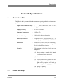
Section 5 Specifications
5.1
5.2
5.3
Guaranteed Data . . . . . . . . . . . . . . . . . . . . . . . . . . . . . . . . . . . . . . . . . . . . . . . . . . . . . . . .
5.1.1 Particle Size Range . . . . . . . . . . . . . . . . . . . . . . . . . . . . . . . . . . . . . . . . . . . . . . . .
5.1.2 Particle Count . . . . . . . . . . . . . . . . . . . . . . . . . . . . . . . . . . . . . . . . . . . . . . . . . . . .
5.1.3 Thresholds . . . . . . . . . . . . . . . . . . . . . . . . . . . . . . . . . . . . . . . . . . . . . . . . . . . . . .
Informative Data . . . . . . . . . . . . . . . . . . . . . . . . . . . . . . . . . . . . . . . . . . . . . . . . . . . . . . . .
5.2.1 Aperture Tube Sizes . . . . . . . . . . . . . . . . . . . . . . . . . . . . . . . . . . . . . . . . . . . . . . .
5.2.2 Metering Volumes . . . . . . . . . . . . . . . . . . . . . . . . . . . . . . . . . . . . . . . . . . . . . . . . .
5.2.3 Data Output . . . . . . . . . . . . . . . . . . . . . . . . . . . . . . . . . . . . . . . . . . . . . . . . . . . . .
Power, Dimensions and Weight . . . . . . . . . . . . . . . . . . . . . . . . . . . . . . . . . . . . . . . . . . . . .
5-1
5-1
5-2
5-2
5-2
5-2
5-2
5-2
5-3
Section 6 Principles of Operation
6.1
6.2
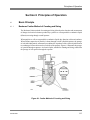
Basic Principle . . . . . . . . . . . . . . . . . . . . . . . . . . . . . . . . . . . . . . . . . . . . . . . . . . . . . . . . .
6.1.1 Coulter Method of Counting and Sizing . . . . . . . . . . . . . . . . . . . . . . . . . . . . . . . . . .
6.1.2 Coincidence Correction . . . . . . . . . . . . . . . . . . . . . . . . . . . . . . . . . . . . . . . . . . . . .
6.1.3 Effect of Diluent (Electrolyte Solution) . . . . . . . . . . . . . . . . . . . . . . . . . . . . . . . . . .
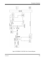
BECKMAN COULTER Z Series Functional Description (Figure 6-2) . . . . . . . . . . . . . . . . .
6.2.1 Pulse Generation . . . . . . . . . . . . . . . . . . . . . . . . . . . . . . . . . . . . . . . . . . . . . . . . . .
6.2.2 Pulse Processing . . . . . . . . . . . . . . . . . . . . . . . . . . . . . . . . . . . . . . . . . . . . . . . . . .
6.2.3 Control Circuits . . . . . . . . . . . . . . . . . . . . . . . . . . . . . . . . . . . . . . . . . . . . . . . . . . .
6-1
6-1
6-2
6-2
6-2
6-2
6-3
6-5
Section 7 Preventative Maintenance
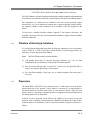
7.1
7.2
7.3
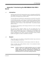
General . . . . . . . . . . . . . . . . . . . . . . . . . . . . . . . . . . . . . . . . . . . . . . . . . . . . . . . . . . . . . . . 7-1
User Testing . . . . . . . . . . . . . . . . . . . . . . . . . . . . . . . . . . . . . . . . . . . . . . . . . . . . . . . . . . . 7-1
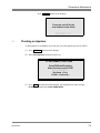
Flushing an Aperture . . . . . . . . . . . . . . . . . . . . . . . . . . . . . . . . . . . . . . . . . . . . . . . . . . . . . 7-4
Section 8 Status and Error Messages ...............................................................................8-1
Appendix 1 Sample Preparation Techniques
A1.1
A1.2
A1.3
A1.4
A1.5
Introduction . . . . . . . . . . . . . . . . . . . . . . . . . . . . . . . . . . . . . . . . . . . . . . . . . . . . . . . . . . .
Aperture Tube Selection . . . . . . . . . . . . . . . . . . . . . . . . . . . . . . . . . . . . . . . . . . . . . . . . .
Selection of Electrolyte Solution . . . . . . . . . . . . . . . . . . . . . . . . . . . . . . . . . . . . . . . . . . . .
Filtration of Electrolyte Solutions . . . . . . . . . . . . . . . . . . . . . . . . . . . . . . . . . . . . . . . . . . . .
Dispersion . . . . . . . . . . . . . . . . . . . . . . . . . . . . . . . . . . . . . . . . . . . . . . . . . . . . . . . . . . . .
A1-1
A1-1
A1-2
A1-3
A1-3
Appendix 2 Aqueous Electrolyte Solutions
PN 9914591
vii
List of Contents
A2.1
Description . . . . . . . . . . . . . . . . . . . . . . . . . . . . . . . . . . . . . . . . . . . . . . . . . . . . . . . . . . . A2-1
Appendix 3 List of Particulate Substances and Suitable Electrolyte Solutions
A3.1
A3.2
Introduction . . . . . . . . . . . . . . . . . . . . . . . . . . . . . . . . . . . . . . . . . . . . . . . . . . . . . . . . . . . A3-1
Key to Aqueous Electrolyte Solutions . . . . . . . . . . . . . . . . . . . . . . . . . . . . . . . . . . . . . . . . A3-2
Appendix 4 Calibration Particles and Aperture Tubes
A4.1
A4.2
A4.3
A4.4
Introduction . . . . . . . . . . . . . . . . . . . . . . . . . . . . . . . . . . . . . . . . . . . . . . . . . . . . . . . . . . .
Latex Suspensions . . . . . . . . . . . . . . . . . . . . . . . . . . . . . . . . . . . . . . . . . . . . . . . . . . . . . .
Redispersion of Calibration Particles . . . . . . . . . . . . . . . . . . . . . . . . . . . . . . . . . . . . . . . . .
Determination of Assayed Sizes . . . . . . . . . . . . . . . . . . . . . . . . . . . . . . . . . . . . . . . . . . . .
A4-1
A4-1
A4-1
A4-2
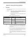
Appendix 5 Salt Water Contaminants
A5.1
A5.2
Introduction . . . . . . . . . . . . . . . . . . . . . . . . . . . . . . . . . . . . . . . . . . . . . . . . . . . . . . . . . . .
Sample Analysis . . . . . . . . . . . . . . . . . . . . . . . . . . . . . . . . . . . . . . . . . . . . . . . . . . . . . . .
A5.2.1 Dual Threshold Version . . . . . . . . . . . . . . . . . . . . . . . . . . . . . . . . . . . . . . . . . . . .
A5.2.2 Single Threshold Version . . . . . . . . . . . . . . . . . . . . . . . . . . . . . . . . . . . . . . . . . . .
A5-1
A5-1
A5-1
A5-4
Appendix 6 Parenteral Samples
A6.1
A6.2
A6.3
A6.4
A6.5
A6.6
Extracts from British Pharmacopoeia, 1993, Parenteral Preparations . . . . . . . . . . . . . . . . .
A6.1.1 Particulate Matter (Reference B.P., 1993, page 748) . . . . . . . . . . . . . . . . . . . . . . .
A6.1.2 Limit Test for Particulate Matter ( Reference B.P., 1993, Appendix XIII, A163) . . .
Preparation . . . . . . . . . . . . . . . . . . . . . . . . . . . . . . . . . . . . . . . . . . . . . . . . . . . . . . . . . . .
A6.2.1 Non-Conducting and Viscous Samples . . . . . . . . . . . . . . . . . . . . . . . . . . . . . . . . .
A6.2.2 Precautions During Analysis . . . . . . . . . . . . . . . . . . . . . . . . . . . . . . . . . . . . . . . .
Calibration . . . . . . . . . . . . . . . . . . . . . . . . . . . . . . . . . . . . . . . . . . . . . . . . . . . . . . . . . . .
Background Count . . . . . . . . . . . . . . . . . . . . . . . . . . . . . . . . . . . . . . . . . . . . . . . . . . . . . .
Sample Analysis . . . . . . . . . . . . . . . . . . . . . . . . . . . . . . . . . . . . . . . . . . . . . . . . . . . . . . .
A6.5.1 Dual Threshold Version . . . . . . . . . . . . . . . . . . . . . . . . . . . . . . . . . . . . . . . . . . . .
A6.5.2 Single Threshold Version . . . . . . . . . . . . . . . . . . . . . . . . . . . . . . . . . . . . . . . . . . .
Origin of Contaminants in Parenteral Fluids . . . . . . . . . . . . . . . . . . . . . . . . . . . . . . . . . . . .
A6-1
A6-1
A6-1
A6-1
A6-1
A6-2
A6-3
A6-3
A6-3
A6-4
A6-5
A6-6
Appendix 7 Disinfecting the COULTER Z Series
A7.1
A7.2
A7.3
viii
Introduction . . . . . . . . . . . . . . . . . . . . . . . . . . . . . . . . . . . . . . . . . . . . . . . . . . . . . . . . . . .
General . . . . . . . . . . . . . . . . . . . . . . . . . . . . . . . . . . . . . . . . . . . . . . . . . . . . . . . . . . . . . .
Method . . . . . . . . . . . . . . . . . . . . . . . . . . . . . . . . . . . . . . . . . . . . . . . . . . . . . . . . . . . . .
A7.3.1 Hypochlorite Bleach . . . . . . . . . . . . . . . . . . . . . . . . . . . . . . . . . . . . . . . . . . . . . .
A7.3.2 Alternative Disinfectants . . . . . . . . . . . . . . . . . . . . . . . . . . . . . . . . . . . . . . . . . . .
A7-1
A7-1
A7-2
A7-2
A7-2
PN 9914591
List of Contents
A7.4
A7.5
A7.3.2.1 Glutaraldehyde . . . . . . . . . . . . . . . . . . . . . . . . . . . . . . . . . . . . . . . . . . .
A7.3.2.2 Gigasept . . . . . . . . . . . . . . . . . . . . . . . . . . . . . . . . . . . . . . . . . . . . . . .
A7.3.2.3 Important Note . . . . . . . . . . . . . . . . . . . . . . . . . . . . . . . . . . . . . . . . . . .
A7.3.2.4 Used (Contaminated) Solution . . . . . . . . . . . . . . . . . . . . . . . . . . . . . . . .
Disinfecting . . . . . . . . . . . . . . . . . . . . . . . . . . . . . . . . . . . . . . . . . . . . . . . . . . . . . . . . . . .
A7.4.1 Draining the System . . . . . . . . . . . . . . . . . . . . . . . . . . . . . . . . . . . . . . . . . . . . . .
A7.4.2 Filling the System with Disinfectant Solution . . . . . . . . . . . . . . . . . . . . . . . . . . . . .
A7.4.3 Removing Disinfectant Solution . . . . . . . . . . . . . . . . . . . . . . . . . . . . . . . . . . . . . .
A7.4.4 Checking for Residual Bleach . . . . . . . . . . . . . . . . . . . . . . . . . . . . . . . . . . . . . . .
References . . . . . . . . . . . . . . . . . . . . . . . . . . . . . . . . . . . . . . . . . . . . . . . . . . . . . . . . . . .
A7-2
A7-2
A7-3
A7-3
A7-3
A7-3
A7-5
A7-6
A7-6
A7-6
Appendix 8 Blood Cell Counting
A8.1 Installation . . . . . . . . . . . . . . . . . . . . . . . . . . . . . . . . . . . . . . . . . . . . . . . . . . . . . . . . . . .
A8.2 Principles of Operation . . . . . . . . . . . . . . . . . . . . . . . . . . . . . . . . . . . . . . . . . . . . . . . . . .
A8.3 Performance Characteristics and Specifications . . . . . . . . . . . . . . . . . . . . . . . . . . . . . . . .
A8.3.1 Specifications (Blood Cell Counts) . . . . . . . . . . . . . . . . . . . . . . . . . . . . . . . . . . . . . . . . . .
A8.3.2 Informative Data . . . . . . . . . . . . . . . . . . . . . . . . . . . . . . . . . . . . . . . . . . . . . . . . . . . . . . .
A8.4 Operational Technique for Human Red Cell Counts (RBC) . . . . . . . . . . . . . . . . . . . . . . . .
A8.4.1 Operational Technique for Human White Cell Counts (WBC) . . . . . . . . . . . . . . . .
A8.4.2 Operational Technique for Human Platelet Counts (PLT) . . . . . . . . . . . . . . . . . . .
A8.4.3 Quality Control . . . . . . . . . . . . . . . . . . . . . . . . . . . . . . . . . . . . . . . . . . . . . . . . . .
A8.5 Calibration Procedures . . . . . . . . . . . . . . . . . . . . . . . . . . . . . . . . . . . . . . . . . . . . . . . . . . .
A8.6 Operational Precautions and Limitations . . . . . . . . . . . . . . . . . . . . . . . . . . . . . . . . . . . . . .
A8.7 Hazards . . . . . . . . . . . . . . . . . . . . . . . . . . . . . . . . . . . . . . . . . . . . . . . . . . . . . . . . . . . . .
A8.8 Service and Maintenance . . . . . . . . . . . . . . . . . . . . . . . . . . . . . . . . . . . . . . . . . . . . . . . . .
A8-1
A8-1
A8-1
A8-1
A8-2
A8-3
A8-4
A8-6
A8-8
A8-8
A8-8
A8-8
A8-9
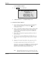
Appendix 9 Operational Technique for Non-Human Cell Counts . . . . . . . . . . . A9-1
A9.2
A9.3
A9.4
Operational Technique for Non-Human Red Cell Counts (RBC) . . . . . . . . . . . . . . . . . . . . A9-2
Operational Technique for Non-Human White Cell Counts (WBC) . . . . . . . . . . . . . . . . . . . A9-5
Operational Technique for Non-Human Platelet Cell Counts (PLT) . . . . . . . . . . . . . . . . . . A9-6
Appendix 10 Finding Optimum Count Settings for Counting Cells and
Other ‘Monodisperse’ Populations when their Sizes are Known
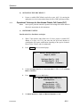
A10.1 Introduction . . . . . . . . . . . . . . . . . . . . . . . . . . . . . . . . . . . . . . . . . . . . . . . . . . . . . . . . . . A10-1
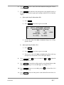
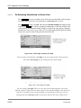
A10.2 Establishing the Correct Current and Gain . . . . . . . . . . . . . . . . . . . . . . . . . . . . . . . . . . . . A10-2
A10.2.1
Procedure . . . . . . . . . . . . . . . . . . . . . . . . . . . . . . . . . . . . . . . . . . . . . . . . . A10-2
A10.2.2
Re-Optimizing Automatically in Volume Units . . . . . . . . . . . . . . . . . . . . . . . A10-4
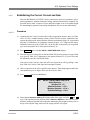
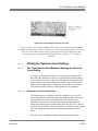
A10.3 Finding the Optimum Count Settings . . . . . . . . . . . . . . . . . . . . . . . . . . . . . . . . . . . . . . . . A10-6
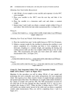
A10.3.1The `Three-Quarter Size' Method of Entering the Optimum Count Setting . . . . . . . A10-6
A10.3.1.1 Estimation of Cell or Particle Size . . . . . . . . . . . . . . . . . . . . . . . . . . . . . . . . . . . . . . . A10-6
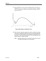
A10.3.2 Determination of the Optimum Count Setting by ‘Plateau’ or ‘Trough’ Finding . . . . . . A10-11
A10.3.2.1 Restrictions of the ‘Plateau Method’ . . . . . . . . . . . . . . . . . . . . . . . . . . . . . . . . . . . . . . A10-14
PN 9914591
ix
List of Contents
A10.3.3
Count Comparison Method . . . . . . . . . . . . . . . . . . . . . . . . . . . . . . . . . . . . . . . . A10-15
A10.4 Updating the Optimum Count Setting Value with Kd Changes . . . . . . . . . . . . . . . . . A10-15
List of Illustrations
Figure
Page
2-1
2-2
2-3
2-4
2-5
2-6
2-7
2-8
Unpacking . . . . . . . . . . . . . . . . . . . . . . . . . . . . . . . . . . . . . . . . . . . . . . . . . . . . . . . . . . . 2-1
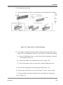
Packing Tray Contents . . . . . . . . . . . . . . . . . . . . . . . . . . . . . . . . . . . . . . . . . . . . . . . . . 2-2
Voltage Selector Card/Fuse Housing . . . . . . . . . . . . . . . . . . . . . . . . . . . . . . . . . . . . . 2-4
Local Supply Voltage Orientation . . . . . . . . . . . . . . . . . . . . . . . . . . . . . . . . . . . . . . . . 2-5
Front Panel . . . . . . . . . . . . . . . . . . . . . . . . . . . . . . . . . . . . . . . . . . . . . . . . . . . . . . . . . . 2-7
Rear Panel . . . . . . . . . . . . . . . . . . . . . . . . . . . . . . . . . . . . . . . . . . . . . . . . . . . . . . . . . . 2-11
Connection Diagram . . . . . . . . . . . . . . . . . . . . . . . . . . . . . . . . . . . . . . . . . . . . . . . . . 2-13
Installing the Aperture Tube, Electrode Assembly and Stirrer Paddle . . . . . . . . 2-14
4-1
Replacing the Aperture Tube . . . . . . . . . . . . . . . . . . . . . . . . . . . . . . . . . . . . . . . . . . 4-22
6-1
6-2
Coulter Method of Counting and Sizing . . . . . . . . . . . . . . . . . . . . . . . . . . . . . . . . . . . 6-1
BECKMAN COULTER Z Series Functional Diagram . . . . . . . . . . . . . . . . . . . . . . . 6-4
A9-1 Example of Setting RBC Count Lower Size Setting . . . . . . . . . . . . . . . . . . . . . . . A9-5
A9-2 Example of Setting Plt Count Size Settings . . . . . . . . . . . . . . . . . . . . . . . . . . . . . . A9-8
A10-1 Size Range of Display Too High . . . . . . . . . . . . . . . . . . . . . . . . . . . . . . . . . . . . . . . A10-4
A10-2 Size Setting Too High . . . . . . . . . . . . . . . . . . . . . . . . . . . . . . . . . . . . . . . . . . . . . . . A10-4
A10-3 Correctly Positioned Pulses for the "Plateau Method" . . . . . . . . . . . . . . . . . . . . A10-5
A10-4 Size Range of Display Too Low . . . . . . . . . . . . . . . . . . . . . . . . . . . . . . . . . . . . . . . A10-6
A10-5 Moving the Threshold Line Manually . . . . . . . . . . . . . . . . . . . . . . . . . . . . . . . . . A10-7
A10-6 Correctly Positioned Pulses for Calibration . . . . . . . . . . . . . . . . . . . . . . . . . . . . A10-10
A10-7 Calibration Size Range of Display Too Low . . . . . . . . . . . . . . . . . . . . . . . . . . . . A10-10
A10-8 Calibration Size Setting Too High . . . . . . . . . . . . . . . . . . . . . . . . . . . . . . . . . . . . A10-11
A10-9 Principle of the "Plateau Method" . . . . . . . . . . . . . . . . . . . . . . . . . . . . . . . . . . . A10-12
A10-10 Example of Plots for the "Plateau" and "Trough" Method . . . . . . . . . . . . . . . A10-14
x
PN 9914591
List of Contents
List of Tables
Tables
Page
2-1
COULTER Z Series Connectors . . . . . . . . . . . . . . . . . . . . . . . . . . . . . . . . . . . . . . . . 2-10
3-1
Metered Volumes Suitable for Selected Aperture Sizes . . . . . . . . . . . . . . . . . . . . . 3-3
4-1
4-2
4-3
Minimum ‘Set Lower Size Tl’ and Suitable Metered Volumes for Selected Aperture
Sizes . . . . . . . . . . . . . . . . . . . . . . . . . . . . . . . . . . . . . . . . . . . . . . . . . . . . . . . . . . . . . . . . . 4-3
Valid Selections for Printer Configuration Screen . . . . . . . . . . . . . . . . . . . . . . . . . . 4-9
‘Counting’ Screen - Screen Items and Function . . . . . . . . . . . . . . . . . . . . . . . . . . . 4-10
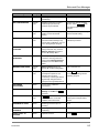
7-1
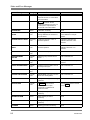
Preventative Maintenance Check List . . . . . . . . . . . . . . . . . . . . . . . . . . . . . . . . . . . 7-1
8-1
Status and Error Messages . . . . . . . . . . . . . . . . . . . . . . . . . . . . . . . . . . . . . . . . . . . . . . 8-1
A1-1 Useful Standard Aperture Tube Data for the BECKMAN COULTER Z Series A1-2
A2-1 Typical Aqueous Electrolyte Solutions . . . . . . . . . . . . . . . . . . . . . . . . . . . . . . . . . . A2-1
A2-2 Stability of Dispersion . . . . . . . . . . . . . . . . . . . . . . . . . . . . . . . . . . . . . . . . . . . . . . . . A2-2
A4-1 Calibration Particles and Aperture Tubes for the COULTER Z Series . . . . . . . A4-1
A8-1 Within Run Precision in the Normal Blood Range (n = 31) . . . . . . . . . . . . . . . . A8-1
A8-2 Linearity Limits . . . . . . . . . . . . . . . . . . . . . . . . . . . . . . . . . . . . . . . . . . . . . . . . . . . . . A8-2
A9-3 Approximate Normal Range and Mean Values for Various Animal Bloods . . . . A9-2
A10
Size Settings Sequence . . . . . . . . . . . . . . . . . . . . . . . . . . . . . . . . . . . . . . . . . . . . A10-5
A10-2A Example of Comparison Matrix for Instrument Counts and Reference
Method. . . . . . . . . . . . . . . . . . . . . . . . . . . . . . . . . . . . . . . . . . . . . . . . . . . . . ..A10-16
A10-2B Evaluation . . . . . . . . . . . . . . . . . . . . . . . . . . . . . . . . . . . . . . . . . . . . . . . . . . . . . A10-16
PN 9914591
xi
List of Contents
xii
PN 9914591
Introduction
Introduction
1.1
System Overview
The BECKMAN COULTER® Z Series systems provide the ability to count particles relative
to user-defined thresholds. The Z Series consists of three models:
(1) The Z1 (single-threshold model) - Allows the user to set one threshold and count all the
particles larger than that threshold.
(2) The Z1 (dual-threshold model) - Allows the user to set two thresholds and count three
regions.
(3) The Z2 - Provides the user with on-screen/printed graphs showing various forms of
channelyzed data (distribution collected by channelyzer, mean, mode, standard deviation).
It also allows all of the counting capabilities of the Z1 (dual-threshold model).
1.2
Manual Description
1.2.1
Scope and Organization
This manual provides the user with the information and procedures needed for operating and
maintaining the Z Series instruments.
The material in this manual is organized into eight chapters, nine appendices, and an index.
1.2.2
Conventions
This manual uses the following conventions:
1.2.3
?
Bold, Helvetica type indicates text appearing on the Data Terminal’s screen. For example:
PRESS ‘START’ TO CONTINUE is a message that appears on the Data Terminal’s
screen.
?
indicates a key on the Data Terminal, such as
function by pressing the key.
SET-UP
. You activate that key
Intended Use
The single and dual threshold models of the BECKMAN COULTER Z Series may be used to
determine the human and animal erythrocyte concentration (or red cell count) RBC, and the
leukocyte concentration (or white cell count) WBC, from blood collected into a suitable
anticoagulant. The Z instrument is a general laboratory use product. For determining
thrombocyte concentration (or platelet count) PLT of human or animal species with a discrete
PN 9914591
1-1
Introduction
RBC and PLT population, a dual threshold Z Series is recommended for simplicity of operation.
Most cell types, due to user selectable size settings, may be analyzed on the Z Series
instruments.
The recommended anticoagulant is K2 EDTA or K3 EDTA, used at a concentration of
1.5mg/mL of blood. Anticoagulated blood may be stored refrigerated (e.g. 4-8?C) for up to 24
hours before RBC, WBC and/or PLT analysis, if required. Re-mix it thoroughly before analysis;
preferably using a rocker-roller mixer.
For analysis, blood must be diluted using a near-physiological saline solution; Beckman Coulter
recommends its ISOTON II diluent, used with a BECKMAN COULTER DILUTER.
Disposable counting vials (ACCUVETTE vials) are available; or regular laboratory glass
beakers may be used to contain the diluted specimen for measurement. To obtain WBC, a lytic
agent is used to remove the unwanted red cells.Beckman Coulter recommends its ZAPOGLOBIN® reagent. To prevent subsequent erroneous RBC and PLT counts due to
contaminating lytic agent, WBC containers should be kept separate. Good laboratory practice
is to clean any re-usable containers in a non-lytic cleaner, e.g.BECKMAN COULTER CLENZ
cleaning agent. In addition, the Z Series should be left with CLENZ cleaning agent around the
aperture, overnight, or when not in regular use.
1.3
Limitations
?
A WARNING indicates a situation or procedure that, if ignored, can cause serious
personal injury.
?
A CAUTION indicates a situation or procedure that, if ignored, can cause damage to the
instrument.
?
A Note contains information that is important to remember or helpful in performing a
procedure.
1.3.1
Chemical
1.3.1.1
Warnings
(1) Do not use non-aqueous electrolyte solutions. The instrument is designed only for aqueous
electrolyte solutions.
(2) Toxicity safety requirements and handling procedures of all reagents should be checked
and adhered to (see Merck Index and/or Material Safety Data Sheets).
(3) Care must be taken in mixing some electrolyte solutions. Violent reactions can occur.
(4) Azide must not be used in acid solutions.
1-2
PN 9914591
Introduction
(5) Flammable electrolyte solutions and organic solvents must not be used in the BECKMAN
COULTER Z Series instruments.
1.3.1.2
Cautions
(1) If the diluent is ISOTON III®, the system must be first drained and then filled with DQ
water to remove all traces of bleach, before filling with ISOTON III diluent.
(2) ISOTON III diluent and sodium hypochlorite must not be mixed together as they react,
releasing gas and inactivating the bleach, possibly making it ineffective in disinfecting the
instrument. Gas trapped in the hydraulic system of the Z Series may result sufficient
internal pressure rise to cause leaks at tubing connections.
(3) If bleach disinfecting an instrument in which ISOTON III diluent has been used, the Vent
Aperture function of the Z Series must be invoked before powering the instrument off
(see para. 2.4.2.3, Screen Access Keys).
1.3.2
Electrical
1.3.2.1
Warnings
(1) High voltages are present inside the instrument, even when the Power Switch is set to O,
due to a.c mains supply being routed from the rear connector to the front panel Power
Switch.
(2) The instrument must be sited on a firm, dry, work bench and must be grounded
correctly.
1.3.2.2
Cautions
(1) If Mains-borne interference occurs, a supply filter or a constant voltage transformer
should be fitted.
(2) Never stand container(s) of fluid on top of the instrument. Repair of any instrument
damaged by fluid being spilt over it, is not covered by the Warranty or Service Contract.
1.3.3
Environmental
1.3.3.1
Warnings
(1) The Vent Aperture function must be selected when an Aperture Tube is being fitted, to
prevent the possibility of liquid being sprayed from the aperture.
PN 9914591
1-3
Introduction
1.3.4
Mechanical
1.3.4.1
Cautions
(1) If the Diluent tubing is disconnected at the instrument instead of from the lid, diluent will
siphon out of the jar.
1.3.4.2
Sources of Error
(1) Only one calibration factor (Kd) can be stored against each letter (A to E). If a letter is
chosen that already has a Kd value, it will be overwritten after calibration.
(2) The Aperture Kd value can be temporarily overwritten by the user (a decimal point is
necessary), in which case the new value will be used until:
(a) Another aperture is selected.
(b) The aperture Kd menu is revisited.
(c) The instrument is switched off (O).
(3) Only one Kd factor can be stored against each letter.
(4) Ultrasonic probes can cause fracture of some types of particles. This is rarely the case
with baths (for recommended models contact Beckman Coulter Particle Characterization
Group or their authorized Distributors).
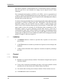
1.3.5
Interfering Substances
The presence of interfering substances, as listed in this section, can yield misleading results.
RBC
? Very high WBC count
? High concentration of very large platelets
? Agglutinated RBCs
? RBCs smaller than 25 fL.
WBC
? Certain unusual RBC abnormalities that resist lysing, nucleated RBCs
? fragmented WBCs
? any unlysed particles greater than 35 fL
? very large or aggregated platelets as when anticoagulated with oxalate or heparin.
PLT
? Very small RBCs near the upper size setting
? Cell fragments
? Clumped platelets as with oxalate or heparin
1-4
PN 9914591
Introduction
?
PN 9914591
Platelet fragments or cellular debris near the lower platelet size setting
1-5
Introduction
1.1
System Overview . . . . . . . . . . . . . . . . . . . . . . . . . . . . . . . . . . . . . . . . . . . . . . . . . . . . . . . . . . 1-1
1.2 Manual Description . . . . . . . . . . . . . . . . . . . . . . . . . . . . . . . . . . . . . . . . . . . . . . . . . . . . . 1-1
1.2.1
Scope and Organization . . . . . . . . . . . . . . . . . . . . . . . . . . . . . . . . . . . . . . . . . . 1-1
1.2.2
Conventions . . . . . . . . . . . . . . . . . . . . . . . . . . . . . . . . . . . . . . . . . . . . . . . . . . . 1-1
1.2.3 IntendedUse..............................................................................................................11
1.3 Operational Warnings and Cautions . . . . . . . . . . . . . . . . . . . . . . . . . . . . . . . . . . . . . . . . 1-2
1.3.1
Chemical . . . . . . . . . . . . . . . . . . . . . . . . . . . . . . . . . . . . . . . . . . . . . . . . . . . . . . 1-2
1.3.1.1 Warnings . . . . . . . . . . . . . . . . . . . . . . . . . . . . . . . . . . . . . . . . . . . . . . . . . . . . . . 1-2
1.3.1.2 Cautions . . . . . . . . . . . . . . . . . . . . . . . . . . . . . . . . . . . . . . . . . . . . . . . . . . . . . . 1-2
1.3.2
Electrical . . . . . . . . . . . . . . . . . . . . . . . . . . . . . . . . . . . . . . . . . . . . . . . . . . . . . . 1-3
1.3.2.1 Warnings . . . . . . . . . . . . . . . . . . . . . . . . . . . . . . . . . . . . . . . . . . . . . . . . . . . . . . 1-3
1.3.2.2 Cautions . . . . . . . . . . . . . . . . . . . . . . . . . . . . . . . . . . . . . . . . . . . . . . . . . . . . . . 1-3
1.3.3
Environmental . . . . . . . . . . . . . . . . . . . . . . . . . . . . . . . . . . . . . . . . . . . . . . . . . . 1-3
1.3.3.1 Warnings . . . . . . . . . . . . . . . . . . . . . . . . . . . . . . . . . . . . . . . . . . . . . . . . . . . . . . 1-3
1.3.4
Mechanical . . . . . . . . . . . . . . . . . . . . . . . . . . . . . . . . . . . . . . . . . . . . . . . . . . . . 1-3
1.3.4.1 Cautions . . . . . . . . . . . . . . . . . . . . . . . . . . . . . . . . . . . . . . . . . . . . . . . . . . . . . . . 1-3
1.3.4.2 Sources of Error . . . . . . . . . . . . . . . . . . . . . . . . . . . . . . . . . . . . . . . . . . . . . . . . . 1-3
CAUTION
definition . . . . . . . . . . . . . . . . . . . . . . . . . . . . . . . . . . . . . . . . . . . . . . . . . . . . . . . . . . . . . 1-2
chemical
cautions . . . . . . . . . . . . . . . . . . . . . . . . . . . . . . . . . . . . . . . . . . . . . . . . . . . . . . . . . . . . . . 1-2
warnings . . . . . . . . . . . . . . . . . . . . . . . . . . . . . . . . . . . . . . . . . . . . . . . . . . . . . . . . . . . . . 1-2
electrical
cautions . . . . . . . . . . . . . . . . . . . . . . . . . . . . . . . . . . . . . . . . . . . . . . . . . . . . . . . . . . . . . .
warnings . . . . . . . . . . . . . . . . . . . . . . . . . . . . . . . . . . . . . . . . . . . . . . . . . . . . . . . . . . . . .
environmental
warnings . . . . . . . . . . . . . . . . . . . . . . . . . . . . . . . . . . . . . . . . . . . . . . . . . . . . . . . . . . . . .
manual
conventions . . . . . . . . . . . . . . . . . . . . . . . . . . . . . . . . . . . . . . . . . . . . . . . . . . . . . . . . . . .
scope and organization . . . . . . . . . . . . . . . . . . . . . . . . . . . . . . . . . . . . . . . . . . . . . . . . . . .
mechanical
cautions . . . . . . . . . . . . . . . . . . . . . . . . . . . . . . . . . . . . . . . . . . . . . . . . . . . . . . . . . . . . . .
sources of error . . . . . . . . . . . . . . . . . . . . . . . . . . . . . . . . . . . . . . . . . . . . . . . . . . . . . . . .
Note
definition . . . . . . . . . . . . . . . . . . . . . . . . . . . . . . . . . . . . . . . . . . . . . . . . . . . . . . . . . . . . .
WARNING
definition . . . . . . . . . . . . . . . . . . . . . . . . . . . . . . . . . . . . . . . . . . . . . . . . . . . . . . . . . . . . .
Z1 (dual-threshold model)
description . . . . . . . . . . . . . . . . . . . . . . . . . . . . . . . . . . . . . . . . . . . . . . . . . . . . . . . . . . . .
Z1 (single-threshold model)
description . . . . . . . . . . . . . . . . . . . . . . . . . . . . . . . . . . . . . . . . . . . . . . . . . . . . . . . . . . . .
Z2
1-6
PN 9914591
1-3
1-3
1-3
1-1
1-1
1-3
1-3
1-2
1-2
1-1
1-1
Introduction
description . . . . . . . . . . . . . . . . . . . . . . . . . . . . . . . . . . . . . . . . . . . . . . . . . . . . . . . . . . . . 1-1
PN 9914591
1-7
Installation
Section 2 Installation
2.1
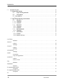
Unpacking
(1) Set the transit case the correct way
up.
Figure
and packing
(2) Open and carefully remove
accessory Tray 1, Tray 2,
and instrument as shown in
2-1. Retain transit case
materials.
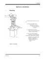
(3) Check that all parts shown in
Figure 2-2 are present, then inspect
all items for transit damage.
(4) Any loss or damage should be
immediately reported to Beckman
Coulter Particle Characterization (using the
installation report supplied), or the
distributor (if supplied by a
Beckman Coulter authorized
distributor), and the
carrier.
Figure 2-1 Unpacking
PN 9914591
2-1
Installation
2-2
PN 9914591
Installation
Figure 2-2 Packing Tray Contents
PN 9914591
2-3
Installation
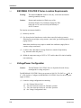
2.2
BECKMAN COULTER Z Series Location Requirements
Warning:
The instrument must be sited on a firm, dry, work bench and must be
earthed (grounded) correctly.
Caution:
Never stand container(s) of fluid on top of the
instrument. Repair of any instrument damaged by fluid
being spilt over it, is not covered by the Warranty or
Service Contract.
The location environment should be:
(1) Relatively dust free.
(2) Free from electrical interferences such as those caused by brush type motors,
flickering fluorescent lights, arcing contacts, water baths, gas chromatographs or bleep
paging systems.
Mains-borne interference may require a suitable line conditioner (supply filter or
constant voltage transformer).
(3) A surface that is not subject to strong vibrations or sounds of high intensity
(e.g. ultrasonic baths and probes).
(4) Within the temperature range of 10?C to 35?C and less than 85% relative humidity
non-condensing.
2.3
Voltage/Power Configuration
Caution:
The BECKMAN COULTER Z Series is dispatched from the factory
unconfigured for voltage and power.
The BECKMAN COULTER Z Series can operate on 100, 120, 220, 240V a.c. + 10%, at
47 - 63Hz inclusive. Configure the BECKMAN COULTER Z Series for the local power
supply as follows:
(1) Locate the voltage configuration kit containing:
(a)
(b)
(c)
(d)
2-4
One Voltage Selector Card.
Two 0.5A (slow blow) fuses for 230/240V operation.
Two 1.0A (slow blow) fuses for 100/120V operation.
One Voltage Configuration Label.
PN 9914591
Installation
(2) Disconnect the power cord.
(3)
Using a small-blade screwdriver (or similar tool), pry the Voltage Selector card/fuse
h
ousin
g
cover
o
ff
(
refer
t
o
F
igure
2
-3).
Figure 2-3 Voltage Selector Card/Fuse Housing
(4) The instrument is shipped with the fuse holder configured for European fuses (refer to
Figure 2-3A). To reconfigure for USA fuses, refer to Figure 2-3B and do the following:
(a) Remove the Phillips-head screw on the left side of the fuse housing/cover and pull
the fuse holder off the cover.
(b) Turn the fuse holder over as indicated by the arrow in Figure 2-3B.
(c) Place the fuse holder on the cover and secure it with the Phillips-head screw.
(5) Select the fuse(s) appropriate to the local supply voltage (para 2.4.3.2).
(6) Fit fuse(s) into the back of the cover (refer to Figure 2-3A and C) and set it aside.
(7) Using the indicator pin, pull the Voltage Selector card straight out of the housing
(refer to Figure 2-3).
PN 9914591
2-5
Installation
(8)
Orient the Voltage
card so that the
voltage is readable at
of the card (refer to
Selector
desired
the bottom
Figure 2-4).
Figure 2-4 Local Supply Voltage Orientation
(7)
Orient the indicator pin so that it points up when the desired voltage is readable at the
bottom of the card (refer to Figure 2-4)
(8)
Insert the Voltage Selector Card into the housing with the printed side of the card
facing toward the three-prong line cord connector and the edge showing the desired
voltage first (refer to Figure 2-3).
(9)
Select the fuse appropriate to the local supply voltage (refer to Figure 2-4).
(10) Fit fuse into the back of the cover (refer to Figure 2-3) and replace the cover.
(11) Verify that the indicator pin shows the desired voltage.
(12) Ensure that a suitable plug is fitted to the power
cord/mains lead. The connections must be made in
accordance with the local safety regulations. The
European mains lead color coding is:
2-6
PN 9914591
Installation
BROWN:
BLUE:
GREEN and YELLOW:
Live
Neutral
Earth (Ground).
2.4
Controls and Connectors
2.4.1
Front Panel (Figure 2-5)
Warning: High voltages are present inside the instrument, even when the Power Switch is
set to off (O), due to a.c mains supply being routed from the rear connector to
the front panel Power Switch.
Power Switch
l
O
Power off.
Adjusts the stirrer paddle height (approximately
28mm adjustment).
Stirrer Position
Stirrer Speed
Power on. A screen appears on the Data
Terminal.
O
Stirrer off.
Rotate clockwise to increase speed. Stirrer
operates only when Sample Platform is in raised
position.
2.4.2
Platform Release
Catch
Adjust sample platform height by pressing and
holding the Platform Release Catch.
Focus Control Body
Center image on Aperture Viewing Screen by
rotating Focus Control Body or moving it in or out.
Focus Control Knob
Focus the aperture image on the Aperture Viewing
screen by rotating the Focus Control Knob.
Aperture Lamp
Illuminates when door is open and during analysis.
Data Terminal
The user area of the Data Terminal is divided into three sections (Figure 2-5). The section
on the left houses the numeric key pad. The section in the middle houses the cursor keys.
The section on the right houses the screen access keys.
2.4.2.1
PN 9914591
Numeric Key Pad
2-7
Installation
The numeric key pad (Figure 2-5) is composed of the numbers 0 through 9, a decimal
point and a ‘Delete’ key. Use these keys to enter numerical values where required.
2.4.2.2
Cursor Keys
There are four keys that control cursor movement (Figure 2-5). In text these keys are
referred to as ‘cursor keys.’
Press to move the cursor as follows:
Use
?
or
to move the cursor up or down one line at a time.
Use < and > to move the cursor left or right, either one selection (Selection Field) at
a time, or one digit (Numeric Entry Field) at a time.
2-8
PN 9914591
Installation
Figure 2-5 Front Panel
PN 9914591
2-9
Installation
2.4.2.3
Screen Access Keys
The following seven screen access keys (Figure 2-5) give the operator access to all the
screens in the Z Series environment:
2
SET-UP
Press SET-UP to gain access to the Setup screens. With a Setup
screen displayed, pressing SET-UP steps the operator through the
following screens:
S1: SETUP - ENTER SIZE DATA
S2: SETUP - ENTER ANALYSIS DATA
S3: SETUP - INSTRUMENT SETTINGS
S10: SETUP - CHANNELYZER SETTINGS
S4: SETUP - APERTURE SELECTION
The Setup screens allows the instrument parameters to be reviewed
prior to sample analysis. Refer to Section 4, Operation, for a full
explanation.
CAL
Press CAL to gain access to the Calibration screens. With a
Calibration Screen displayed, pressing CAL steps the operator
through the following screens:
C1: CALIBRATION
C2: CALIBRATION FACTOR
C3: CAL - INSTRUMENT SETTINGS
The Calibration screens allow the instrument parameters to be
reviewed prior to calibration. See Section 3, Calibration, for a full
explanation.
OUTPUT
Press OUTPUT to gain access to the Analysis screens. With an
Analysis screen displayed, pressing OUTPUT steps the operator
through the following screens:
A1: ANALYSIS - OUTPUT FORMAT
A10: PRINTOUT CONFIGURATION
A4: ANALYSIS RESULT
A7: CHANNELYSER RESULTS
Analysis screens allow output parameters to be reviewed before and
after an analysis. Refer to Section 4, Operation, for a full explanation.
UNBLOCK
2-10
Press UNBLOCK to unblock the aperture. This procedure reverses
the flow of sample through the aperture, causing any debris to be
expelled.
PN 9914591
Installation
PRINT
Press PRINT to print results or select Automatic printout from an
Analysis screen.
FUNCTIONS
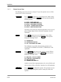
Press
FUNCTIONS to gain access to the F1: INSTRUMENT
FUNCTIONS screen. From there, select any of the following
automated procedures:
Note:
Press
Prime Aperture
Fill System
START
Required when an Aperture Tube needs filling or
when the rest of the Hydraulic System is full of
electrolyte solution (or diluent).
Used to re-establish a low background count at
startup,and between sample runs.
Completely fills the Hydraulic System with diluent
and removes air bubbles. Required at installation
or when the system has been drained of diluent.
Drain Aperture
Empties the Aperture Tube of diluent without
draining the Hydraulics System.
Drain System
Drains the entire Hydraulics System of diluent.
Required when type of diluent is changed. Diluent
Tube must be placed in a Waste Container during
this procedure.
Flush Aperture
Flushes particles or air bubbles away from the rear
of the aperture.
Vent Aperture
Vents interior of the aperture to atmosphere. The
Aperture Tube is automatically vented at the end
of the Drain Aperture and Drain System functions.
Load Profile
Lets you load specific stored profiles.
Store Profile
Lets you name and store specific profiles.
Set Clock
Lets you set the Z2's real-time clock with the date
and time.
User Testing
Lets you self-test the following functions:
?
?
?
?
?
PN 9914591
to initiate any selected function.
Software Versions
Keyboard
Display
Metering Pump
Control Valve
2-11
Installation
? Default Settings.
2-12
PN 9914591
Installation
Press this key to start or stop a selected procedure. If a procedure is
stopped, the instrument electronics and hydraulics systems are
automatically reset.
START
STOP
Note: This key is shown in text as either START or STOP
depending on whether you want to stop or start a procedure.
Message Area
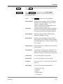
2.4.2.4
The Z Series interacts with the operator through ‘messages’ at the bottom of the Data
Terminal’s LCD display (see Figure 2-5). These messages appear during the analysis and
data entry phases of operation. Messages can be status messages or error messages
(divided into analysis errors and data entry errors). For a complete listing of messages,
type of message, reason for message and action to take, see Section 8, Status and Error
Messages.
2.4.3
Rear Panel
2.4.3.1
Connectors (Figure 2-6)
Table 2-1 BECKMAN COULTER Z Series Connectors
Connector
Function
WASTE
Stainless steel tubing
connector
Connection to Waste Container (Either Jar or Z Pak ®)
DILUENT
Stainless steel tubing
connector
Connection to Diluent Container (Either Jar or Z Pak )
LEVEL SENSE
3-way jack sockets
PARALLEL PRINTER
25-pin 'D' type socket
(IBM® compatible)
K/BOARD
7-way DIN socket
PN 9914591
Connection to level sensors in the Diluent and Waste Jars or Z Pak
(connectors are interchangeable). The sensor in the Diluent Jar is activated
when the diluent level falls below it. The sensor at the top of the Waste Jar is
activated when the waste level reaches it.
Connection to parallel Centronics Printer.
Connection to Data Terminal.
2-13
Installation
Connector
Power
IEC 320/CEE Standard
3-pin plug
External Control Port
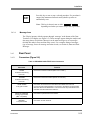
2.4.3.2
Function
Connection to a.c. Power Supply. An integral Voltage Selector Card allows
the instrument to be configured over a wide range of line voltages.
For future use.
Fuses
Exter
fuses
F2
have
al
nal
F1 and
must
identic
values:
eithe
0.5A
220/2
or
for
0V.
r
for
40V
1.0A
100/12
2.4.3.
Pow
Sup
Indic
When
+15v,
+5v
225v
ors
the
d.c.
suppl
availa
3
er
ply
ators
lit,
-15v,
and indicat
show
marked
power
y is
ble.
2-14
PN 9914591
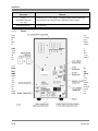
Installation
Figure 2-6 Rear Panel
PN 9914591
2-15
Installation
2.5
Start-Up Procedure
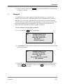
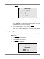
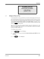
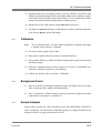
2.5.1
Setting the Time and Date
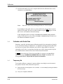
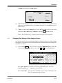
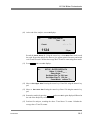
(1) Press
FUNCTIONS
and screen F1 displays.
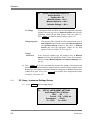
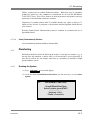
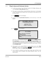
(2) Using the cursor keys, move to the line below Select function, press START and
select Set Clock.
F1:
INSTRUMENT FUNCTIONS
Prime/Fill/Drain/Flush/Vent
Select function, press START
< Set Clock >
Key beep < On >
Printer: < LaserJet >
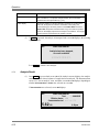
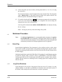
(3) Press
START
and screen F5 displays.
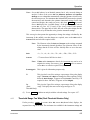
(4) Enter the date and time in the format shown on the screen (mm/dd/yy hh:mm).
Note: A 24-hour clock is used.
F5:
SET CLOCK
Enter the current time below.
Press START to set the time
mm/dd/yyyy hh:mm
00/00/0000 00:00
(5) Press
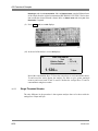
2.5.2
2-16
START
and the date/time is set and you are returned to the F1 screen.
Connections
(1)
Remove the tubing link between the back panel waste and diluent connectors (see
Figure 2-7).
(2)
Fill the Diluent Jar with clean electrolyte solution (e.g. ISOTON II diluent).
(3)
When using the Z Pak, follow (1). Connect the waste and diluent tubing directly to
the Z Pak . Diluent is already supplied within the Z Pak diluent container.
(4)
Diluent Dispenser connects to the top of the Diluent Sensor on the Z Pak.
PN 9914591
Installation
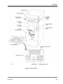
Figure 2-7 Connection Diagram
NOTE: For Z Pak: Connect Waste line to Z Pak waste connector. Connect diluent
PN 9914591
2-17
Installation
line to the Diluent Connection on the Diluent Sensor of the Z Pak. Dispenser connects to the top of the
dil
uent
se
nsor
de
signed
for
the Z
Pa
k.
2-18
PN 9914591
Installation
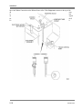
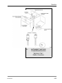
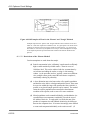
Figure 2-8 Installing the Aperture Tube, Electrode Assembly and Stirrer Paddle
PN 9914591
2-19
Installation
(5)
Connect the Waste and Diluent Containers as shown in Figure 2-7.
Note: Level Sense connectors are interchangeable.
2.5.3
(6)
Connect the Data Terminal as shown in Figure 2-7.
(7)
Connect the Printer (optional extra) to the Parallel Printer connector (see Figure 2-7).
Refer to the relevant manufacturer's manual.
(8)
Connect the instrument to the mains supply and set the Power Switch (see Figure 25) to I (on). The Data Terminal first displays the Coulter logo, software version
number, and date and time followed by the S1: SETUP - ENTER SIZE DATA screen.
Fitting the Aperture Tube, Electrode Assembly and Stirrer
(1)
Select an Aperture Tube in the range 50µm to 200µm. Rinse the Aperture Tube,
beaker, Electrode Assembly and stirrer in clean diluent. Discard diluent.
(2)
Open the Screened Door, the aperture lamp will illuminate. Move the platform to its
lowest position.
Caution:
If the electrode is pulled/pushed by it glass stem, damage may be
caused to the electrode leading to erroneous results. Hold the electrode
by the metal fitting only.
(3)
Offer the electrode assembly to its socket as shown in Figure 2-8. The Electrode
Assembly is keyed to ensure correct location.
(4)
Put the Aperture Tube into its socket in the orientation shown in Figure 2-8, with the
Beckman Coulter logo facing away from you. Secure by fully rotating in direction
shown. In its final position the aperture is oriented towards the FOCUS control but
may not directly face it (Figure 2-10). The aperture is slightly angled to produce an
optimum image on the aperture viewing screen and this angle must not be adjusted.
(5)
Turn the Stirrer Position control fully clockwise, hold the stirrer collet with finger and
thumb, then press fit the Stirrer Paddle (see Figure 2-8). Ensure Stirrer Speed Control
is set to O.
Note: The Stirrer Paddle cannot be used with an ACCUVETTE® sample container
or a small vial.
(6)
2-20
Fill the beaker with clean diluent, place it on the platform. Raise the platform until the
Aperture Tube, Electrode Assembly and stirrer are fully immersed. Close the
Screened Door.
PN 9914591
Installation
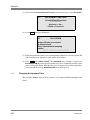
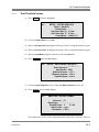
2.5.4
Filling the System
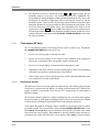
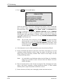
(1)
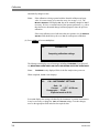
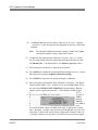
Press
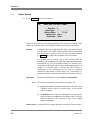
(2)
At the line under Prime/Fill/Drain/Flush/Vent, use the cursor keys to select Fill
System.
FUNCTIONS
to select the F1 screen.
F1:
INSTRUMENT FUNCTIONS
Prime/Fill/Drain/Flush/Vent
< Fill System >
Key beep < On >
Printer: < LaserJet >
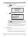
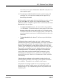
(3)
Using the cursor keys, move to Key beep and select either On or Off.
Note: If On is selected, pressing a Data Terminal key produces a beep.
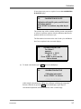
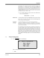
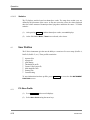
(4)
Press
START
and screen F3 displays:
F3:
FILL SYSTEM
Ensure fill tube is connected
to diluent vessel.
Place clean diluent at sampling
station.
PRESS ’ START ’ TO CONTINUE
Follow the instructions on screen F3. The PRESS ‘START’ TO CONTINUE status
message is replaced by FILLING SYSTEM xx, where xx is the number of cycles
required to completion. When the final cycle is completed, screen F3 is replaced by
screen F1 with the message SYSTEM FILLED in the Message area.
2.5.5
PN 9914591
Adjusting the Optics
(1)
Open the Screened Door, the aperture lamp lights.
(2)
Position the aperture image at the center of the Aperture Viewing Screen by rotating
and/or moving the FOCUS control body in and out.
(3)
To focus the image, rotate the FOCUS control knob clockwise/counterclockwise.
(4)
The BECKMAN COULTER Z Series is now ready for use. Before running samples,
the instrument should be calibrated using one of the procedures described in Section
3, Calibration.
2-21
Installation
2-22
PN 9914591
Installation
CONTENTS
2.1 Unpacking . . . . . . . . . . . . . . . . . . . . . . . . . . . . . . . . . . . . . . . . . . . . . . . . . . . . . . . . . . . . 2-1
2.2 BECKMAN COULTER Z Series Location Requirements . . . . . . . . . . . . . . . . . . . . . . 2-3
2.3 Voltage/Power Configuration . . . . . . . . . . . . . . . . . . . . . . . . . . . . . . . . . . . . . . . . . . . . . 2-3
2.4 Controls and Connectors . . . . . . . . . . . . . . . . . . . . . . . . . . . . . . . . . . . . . . . . . . . . . . . . 2-5
2.4.1 Front Panel (Figure 2-5) . . . . . . . . . . . . . . . . . . . . . . . . . . . . . . . . . . . . . . . . . . . . . . . 2-5
2.4.2 Data Terminal . . . . . . . . . . . . . . . . . . . . . . . . . . . . . . . . . . . . . . . . . . . . . . . . . . . . . . . 2-6
2.4.2.1 Numeric Key Pad . . . . . . . . . . . . . . . . . . . . . . . . . . . . . . . . . . . . . . . . . . . . . . . . 2-6
2.4.2.2 Cursor Keys . . . . . . . . . . . . . . . . . . . . . . . . . . . . . . . . . . . . . . . . . . . . . . . . . . . 2-6
2.4.2.3 Screen Access Keys . . . . . . . . . . . . . . . . . . . . . . . . . . . . . . . . . . . . . . . . . . . . . 2-8
2.4.2.4 Message Area . . . . . . . . . . . . . . . . . . . . . . . . . . . . . . . . . . . . . . . . . . . . . . . . . 2-10
2.4.3 Rear Panel . . . . . . . . . . . . . . . . . . . . . . . . . . . . . . . . . . . . . . . . . . . . . . . . . . . . . . . . 2-10
2.4.3.1 Connectors (Figure 2-6) . . . . . . . . . . . . . . . . . . . . . . . . . . . . . . . . . . . . . . . . . 2-10
2.4.3.2 Fuses . . . . . . . . . . . . . . . . . . . . . . . . . . . . . . . . . . . . . . . . . . . . . . . . . . . . . . . . 2-11
2.4.3.3 Power Supply Indicators . . . . . . . . . . . . . . . . . . . . . . . . . . . . . . . . . . . . . . . . . 2-11
2.5 Start-Up Procedure . . . . . . . . . . . . . . . . . . . . . . . . . . . . . . . . . . . . . . . . . . . . . . . . . . . . 2-12
2.5.1 Setting the Time and Date . . . . . . . . . . . . . . . . . . . . . . . . . . . . . . . . . . . . . . . . . . . . 2-12
2.5.2 Connections . . . . . . . . . . . . . . . . . . . . . . . . . . . . . . . . . . . . . . . . . . . . . . . . . . . . . . . 2-12
2.5.3 Fitting the Aperture Tube, Electrode Assembly and Stirrer . . . . . . . . . . . . . . . . . 2-14
2.5.5 Adjusting the Optics . . . . . . . . . . . . . . . . . . . . . . . . . . . . . . . . . . . . . . . . . . . . . . . . . 2-16
ILLUSTRATIONS
Figure 2-1 Unpacking . . . . . . . . . . . . . . . . . . . . . . . . . . . . . . . . . . . . . . . . . . . . . . . . . . . . . . . . . . . 2-1
Figure 2-2 Packing Tray Contents . . . . . . . . . . . . . . . . . . . . . . . . . . . . . . . . . . . . . . . . . . . . . . . . . 2-2
Figure 2-3 Voltage Selector Card/Fuse Housing . . . . . . . . . . . . . . . . . . . . . . . . . . . . . . . . . . . . . . 2-4
Figure 2-4 Local Supply Voltage Orientation . . . . . . . . . . . . . . . . . . . . . . . . . . . . . . . . . . . . . . . . . 2-4
Figure 2-5 Front Panel . . . . . . . . . . . . . . . . . . . . . . . . . . . . . . . . . . . . . . . . . . . . . . . . . . . . . . . . . . 2-7
Figure 2-6 Rear Panel . . . . . . . . . . . . . . . . . . . . . . . . . . . . . . . . . . . . . . . . . . . . . . . . . . . . . . . . . 2-11
Figure 2-7 Connection Diagram . . . . . . . . . . . . . . . . . . . . . . . . . . . . . . . . . . . . . . . . . . . . . . . . . 2-13
Figure 2-8 Installing the Aperture Tube, Electrode Assembly and Stirrer Paddle . . . . . . . . . . . 2-15
TABLES
Table 2-1 BECKMAN COULTER Z Series Connectors . . . . . . . . . . . . . . . . . . . . . . . . . . . . . . 2-10
INDEX
Aperture Lamp
description . . . . . . . . . . . . . . . . . . . . . . . . . . . . . . . . . . . . . . . . . . . . . . . . . . . . . . . . . . . . . . . . 2-6
Aperture Tube
draining . . . . . . . . . . . . . . . . . . . . . . . . . . . . . . . . . . . . . . . . . . . . . . . . . . . . . . . . . . . . . . . . . . . 2-9
illustration, installation . . . . . . . . . . . . . . . . . . . . . . . . . . . . . . . . . . . . . . . . . . . . . . . . . . . . . . . 2-15
priming . . . . . . . . . . . . . . . . . . . . . . . . . . . . . . . . . . . . . . . . . . . . . . . . . . . . . . . . . . . . . . . . . . . 2-9
Aperture Viewing Screen
positioning . . . . . . . . . . . . . . . . . . . . . . . . . . . . . . . . . . . . . . . . . . . . . . . . . . . . . . . . . . . . . . . . 2-16
Cal key
function . . . . . . . . . . . . . . . . . . . . . . . . . . . . . . . . . . . . . . . . . . . . . . . . . . . . . . . . . . . . . . . . . . 2-8
PN 9914591
2-23
Installation
clock
setting date and time . . . . . . . . . . . . . . . . . . . . . . . . . . . . . . . . . . . . . . . . . . . . . . . . . . . . . . . . . 2-9
connections
illustration . . . . . . . . . . . . . . . . . . . . . . . . . . . . . . . . . . . . . . . . . . . . . . . . . . . . . . . . . . . . . . . . 2-16
connectors
diluent . . . . . . . . . . . . . . . . . . . . . . . . . . . . . . . . . . . . . . . . . . . . . . . . . . . . . . . . . . . . . . . . . . . 2-10
external control port . . . . . . . . . . . . . . . . . . . . . . . . . . . . . . . . . . . . . . . . . . . . . . . . . . . . . . . . . 2-10
keyboard . . . . . . . . . . . . . . . . . . . . . . . . . . . . . . . . . . . . . . . . . . . . . . . . . . . . . . . . . . . . . . . . . 2-10
level sensors . . . . . . . . . . . . . . . . . . . . . . . . . . . . . . . . . . . . . . . . . . . . . . . . . . . . . . . . . . . . . . 2-10
parallel printer . . . . . . . . . . . . . . . . . . . . . . . . . . . . . . . . . . . . . . . . . . . . . . . . . . . . . . . . . . . . . 2-10
power . . . . . . . . . . . . . . . . . . . . . . . . . . . . . . . . . . . . . . . . . . . . . . . . . . . . . . . . . . . . . . . . . . . 2-10
table, connectors and function . . . . . . . . . . . . . . . . . . . . . . . . . . . . . . . . . . . . . . . . . . . . . . . . . 2-10
waste . . . . . . . . . . . . . . . . . . . . . . . . . . . . . . . . . . . . . . . . . . . . . . . . . . . . . . . . . . . . . . . . . . . 2-10
controls and connectors . . . . . . . . . . . . . . . . . . . . . . . . . . . . . . . . . . . . . . . . . . . . . . . . . . . . . . . . . . . . 2-5
cursor keys
moving . . . . . . . . . . . . . . . . . . . . . . . . . . . . . . . . . . . . . . . . . . . . . . . . . . . . . . . . . . . . . . . . . . . 2-6
Data Terminal
cursor keys . . . . . . . . . . . . . . . . . . . . . . . . . . . . . . . . . . . . . . . . . . . . . . . . . . . . . . . . . . . . . . . . 2-6
description . . . . . . . . . . . . . . . . . . . . . . . . . . . . . . . . . . . . . . . . . . . . . . . . . . . . . . . . . . . . . . . . 2-6
message area . . . . . . . . . . . . . . . . . . . . . . . . . . . . . . . . . . . . . . . . . . . . . . . . . . . . . . . . . . . . . 2-10
numeric key pad . . . . . . . . . . . . . . . . . . . . . . . . . . . . . . . . . . . . . . . . . . . . . . . . . . . . . . . . . . . . 2-6
screen access keys . . . . . . . . . . . . . . . . . . . . . . . . . . . . . . . . . . . . . . . . . . . . . . . . . . . . . . . . . . 2-8
diluent interface . . . . . . . . . . . . . . . . . . . . . . . . . . . . . . . . . . . . . . . . . . . . . . . . . . . . . . . . . . . . . . . . 2-10
Drain Aperture
description . . . . . . . . . . . . . . . . . . . . . . . . . . . . . . . . . . . . . . . . . . . . . . . . . . . . . . . . . . . . . . . . 2-9
Drain System
description . . . . . . . . . . . . . . . . . . . . . . . . . . . . . . . . . . . . . . . . . . . . . . . . . . . . . . . . . . . . . . . . 2-9
Electrode Assembly
illustration, installation . . . . . . . . . . . . . . . . . . . . . . . . . . . . . . . . . . . . . . . . . . . . . . . . . . . . . . . 2-15
European mains lead
color coding . . . . . . . . . . . . . . . . . . . . . . . . . . . . . . . . . . . . . . . . . . . . . . . . . . . . . . . . . . . . . . . 2-5
Fill System
description . . . . . . . . . . . . . . . . . . . . . . . . . . . . . . . . . . . . . . . . . . . . . . . . . . . . . . . . . . . . . . . . 2-9
Flush Aperture
description . . . . . . . . . . . . . . . . . . . . . . . . . . . . . . . . . . . . . . . . . . . . . . . . . . . . . . . . . . . . . . . . 2-9
Focus Control Body
description . . . . . . . . . . . . . . . . . . . . . . . . . . . . . . . . . . . . . . . . . . . . . . . . . . . . . . . . . . . . . . . . 2-6
Focus Control Knob
description . . . . . . . . . . . . . . . . . . . . . . . . . . . . . . . . . . . . . . . . . . . . . . . . . . . . . . . . . . . . . . . . 2-6
Front Panel . . . . . . . . . . . . . . . . . . . . . . . . . . . . . . . . . . . . . . . . . . . . . . . . . . . . . . . . . . . . . . . . . . . . 2-5
Functions key
function . . . . . . . . . . . . . . . . . . . . . . . . . . . . . . . . . . . . . . . . . . . . . . . . . . . . . . . . . . . . . . . . . . 2-9
fuses
description . . . . . . . . . . . . . . . . . . . . . . . . . . . . . . . . . . . . . . . . . . . . . . . . . . . . . . . . . . . . . . . . 2-3
installation . . . . . . . . . . . . . . . . . . . . . . . . . . . . . . . . . . . . . . . . . . . . . . . . . . . . . . . . . . . . . . . . . 2-5
keyboard interface . . . . . . . . . . . . . . . . . . . . . . . . . . . . . . . . . . . . . . . . . . . . . . . . . . . . . . . . . . . . . . 2-10
level sense interfaces . . . . . . . . . . . . . . . . . . . . . . . . . . . . . . . . . . . . . . . . . . . . . . . . . . . . . . . . . . . . 2-10
Load Profile
description . . . . . . . . . . . . . . . . . . . . . . . . . . . . . . . . . . . . . . . . . . . . . . . . . . . . . . . . . . . . . . . . 2-9
location requirements . . . . . . . . . . . . . . . . . . . . . . . . . . . . . . . . . . . . . . . . . . . . . . . . . . . . . . . . . . . . . 2-3
numeric key pad
function . . . . . . . . . . . . . . . . . . . . . . . . . . . . . . . . . . . . . . . . . . . . . . . . . . . . . . . . . . . . . . . . . . 2-6
Output key
2-24
PN 9914591
Installation
function . . . . . . . . . . . . . . . . . . . . . . . . . . . . . . . . . . . . . . . . . . . . . . . . . . . . . . . . . . . . . . . . . . 2-8
Platform Release Catch
description . . . . . . . . . . . . . . . . . . . . . . . . . . . . . . . . . . . . . . . . . . . . . . . . . . . . . . . . . . . . . . . . 2-6
Power Supply indicators
description . . . . . . . . . . . . . . . . . . . . . . . . . . . . . . . . . . . . . . . . . . . . . . . . . . . . . . . . . . . . . . . 2-11
Power Switch
description . . . . . . . . . . . . . . . . . . . . . . . . . . . . . . . . . . . . . . . . . . . . . . . . . . . . . . . . . . . . . . . . 2-5
Prime Aperture
description . . . . . . . . . . . . . . . . . . . . . . . . . . . . . . . . . . . . . . . . . . . . . . . . . . . . . . . . . . . . . . . . 2-9
Print key
function . . . . . . . . . . . . . . . . . . . . . . . . . . . . . . . . . . . . . . . . . . . . . . . . . . . . . . . . . . . . . . . . . . 2-8
printer interface . . . . . . . . . . . . . . . . . . . . . . . . . . . . . . . . . . . . . . . . . . . . . . . . . . . . . . . . . . . . . . . . 2-10
procedures
adjusting the optics . . . . . . . . . . . . . . . . . . . . . . . . . . . . . . . . . . . . . . . . . . . . . . . . . . . . . . . . . 2-16
configuring voltage/power . . . . . . . . . . . . . . . . . . . . . . . . . . . . . . . . . . . . . . . . . . . . . . . . . . . . . 2-3
connections . . . . . . . . . . . . . . . . . . . . . . . . . . . . . . . . . . . . . . . . . . . . . . . . . . . . . . . . . . . . . . . 2-12
SET CLOCK . . . . . . . . . . . . . . . . . . . . . . . . . . . . . . . . . . . . . . . . . . . . . . . . . . . . . . . . . . . . . 2-12
start-up . . . . . . . . . . . . . . . . . . . . . . . . . . . . . . . . . . . . . . . . . . . . . . . . . . . . . . . . . . . . . . . . . . 2-12
unpacking . . . . . . . . . . . . . . . . . . . . . . . . . . . . . . . . . . . . . . . . . . . . . . . . . . . . . . . . . . . . . . . . . 2-1
profiles
load . . . . . . . . . . . . . . . . . . . . . . . . . . . . . . . . . . . . . . . . . . . . . . . . . . . . . . . . . . . . . . . . . . . . . 2-9
store . . . . . . . . . . . . . . . . . . . . . . . . . . . . . . . . . . . . . . . . . . . . . . . . . . . . . . . . . . . . . . . . . . . . . 2-9
Rear Panel . . . . . . . . . . . . . . . . . . . . . . . . . . . . . . . . . . . . . . . . . . . . . . . . . . . . . . . . . . . . . . . . . . . . 2-10
screen access keys . . . . . . . . . . . . . . . . . . . . . . . . . . . . . . . . . . . . . . . . . . . . . . . . . . . . . . . . . . . . . . . 2-8
Set Clock
description . . . . . . . . . . . . . . . . . . . . . . . . . . . . . . . . . . . . . . . . . . . . . . . . . . . . . . . . . . . . . . . . 2-9
procedure . . . . . . . . . . . . . . . . . . . . . . . . . . . . . . . . . . . . . . . . . . . . . . . . . . . . . . . . . . . . . . . . 2-12
Setup key
function . . . . . . . . . . . . . . . . . . . . . . . . . . . . . . . . . . . . . . . . . . . . . . . . . . . . . . . . . . . . . . . . . . 2-8
Start-Up
procedures . . . . . . . . . . . . . . . . . . . . . . . . . . . . . . . . . . . . . . . . . . . . . . . . . . . . . . . . . . . . . . . 2-12
Start/Stop key
function . . . . . . . . . . . . . . . . . . . . . . . . . . . . . . . . . . . . . . . . . . . . . . . . . . . . . . . . . . . . . . . . . 2-10
Stirrer
position . . . . . . . . . . . . . . . . . . . . . . . . . . . . . . . . . . . . . . . . . . . . . . . . . . . . . . . . . . . . . . . . . . . 2-5
speed . . . . . . . . . . . . . . . . . . . . . . . . . . . . . . . . . . . . . . . . . . . . . . . . . . . . . . . . . . . . . . . . . . . . 2-5
Stirrer Paddle
illustration, installation . . . . . . . . . . . . . . . . . . . . . . . . . . . . . . . . . . . . . . . . . . . . . . . . . . . . . . . 2-15
installation . . . . . . . . . . . . . . . . . . . . . . . . . . . . . . . . . . . . . . . . . . . . . . . . . . . . . . . . . . . . . . . . 2-16
Store Profile
description . . . . . . . . . . . . . . . . . . . . . . . . . . . . . . . . . . . . . . . . . . . . . . . . . . . . . . . . . . . . . . . . 2-9
system
draining . . . . . . . . . . . . . . . . . . . . . . . . . . . . . . . . . . . . . . . . . . . . . . . . . . . . . . . . . . . . . . . . . . . 2-9
filling . . . . . . . . . . . . . . . . . . . . . . . . . . . . . . . . . . . . . . . . . . . . . . . . . . . . . . . . . . . . . . . . 2-9, 2-16
installation procedures . . . . . . . . . . . . . . . . . . . . . . . . . . . . . . . . . . . . . . . . . . . . . . . . . . . . . . . . 2-1
Unblock key
function . . . . . . . . . . . . . . . . . . . . . . . . . . . . . . . . . . . . . . . . . . . . . . . . . . . . . . . . . . . . . . . . . . 2-8
unpacking
illustration, components . . . . . . . . . . . . . . . . . . . . . . . . . . . . . . . . . . . . . . . . . . . . . . . . . . . . . . . 2-1
procedures . . . . . . . . . . . . . . . . . . . . . . . . . . . . . . . . . . . . . . . . . . . . . . . . . . . . . . . . . . . . . . . . 2-1
User Testing
description . . . . . . . . . . . . . . . . . . . . . . . . . . . . . . . . . . . . . . . . . . . . . . . . . . . . . . . . . . . . . . . . 2-9
Vent Aperture
PN 9914591
2-25
Installation
description . . . . . . . . . . . . . . . . . . . . . . . . . . . . . . . . . . . . . . . . . . . . . . . . . . . . . . . . . . . . . . . . 2-9
voltage/power
configuration procedure . . . . . . . . . . . . . . . . . . . . . . . . . . . . . . . . . . . . . . . . . . . . . . . . . . . . . . . 2-3
waste interface . . . . . . . . . . . . . . . . . . . . . . . . . . . . . . . . . . . . . . . . . . . . . . . . . . . . . . . . . . . . . . . . . 2-10
2-26
PN 9914591
Calibration
Section 3 Calibration
3.1
Introduction
Each Aperture Tube has its own characteristic calibration constant. It is recommended that
the user checks the size calibration for each Aperture Tube at least once a month to
monitor for any system variations. Calibration may be performed using materials of known
size, for example Beckman Coulter Calibration Latex for non-biological applications, or a
sample of known Mean Cell Volume (MCV) for biological applications. The calibration
methods are automatic and take into account the cell fragility of biological calibrators.
Calibration is written as the non-biological procedure using the modal size of the calibrator,
with the differences from the MCV indicated in the appropriate places. It is also possible to
carry out the mass integration calibration as described in BS3406 Part 5.
This procedure assumes:
(1)
(2)
(3)
(4)
3.2
The instrument is switched on ( I ).
The instrument is fitted with the Aperture Tube to be calibrated.
The instrument is primed with the required diluent.
The operator is familiar with the instrument’s controls and displays (refer to
Section 2.4, Controls and Connectors).
Sample Preparation
(1) Select a calibration sample whose assayed size in equivalent spherical diameter is
within 5 to 20% of the aperture diameter.
Prepare a calibration suspension as recommended in the assay sheet.
(2) Place a beaker of the calibration suspension on the platform and raise the platform until
the Aperture Tube, electrode and stirrer are immersed.
Note: The Screened Door must be closed.
PN 9914591
3-1
Calibration
3.3
Instrument Preparation
(1) Press
SET-UP
and screen S1 displays:
S1:
SETUP - ENTER SIZE DATA
100µm C, Kd=Uncal (60)
Select Units: < µm >
Set Upper Size Tu: 8.0 µm
Set Lower Size Tl: 3.0 µm
Count Mode: < above Tl >
(2) At Select Units there are two choices, either µm , or fl (= µm3 ). Using the cursor keys,
select the required units appropriate to the assay value of the calibrator.
(3) Press
SET-UP
and screen S2 displays:
S2:
SETUP - ENTER ANALYSIS DATA
Select Aperture : <100µm C >
Aperture Kd : Uncal (60)
Metered Volume : < 0.5 >
Measure Aperture : < Yes >
Optimize Settings : < Yes >
(4) At Select Aperture , use the cursor keys to select the size of the Aperture Tube that
has been fitted.
The Aperture Kd field (Diameter calibration constant) changes as you move through
the Select Aperture choices. There are three types of ‘Aperture Kd’ status:
?
Stored Aperture Kd - If a calibration constant is already stored in the
Aperture Selection Table (screen S4: SETUP - APERTURE SELECTION) its
value is displayed in the Aperture Kd field. The Aperture diameter is followed
by a reference letter to identify its position in the Aperture Selection Table.
Example: Select Aperture: < 100µm C >
Aperture Kd: 60.2
?
Uncalibrated Apertures - If an aperture exists in the Aperture Selection
Table, but has not been calibrated, the Aperture Kd field displays Uncal (xxx),
where xxx is the default constant for the selected aperture size. This default
constant may be used for non-critical analysis by entering its value on screen
C2: CALIBRATION FACTOR.
3-2
PN 9914591
Calibration
?
Temporary Kd - Entering a numeric value into Aperture Kd and then leaving
screen S2, temporarily assigns that value to the Select Aperture line. The stored
Kd is not however, overwritten. The reference letter selected with that aperture is
replaced by an * and the label Aperture Kd is replaced by Temp. Aperture Kd.
Only one aperture size at a time can be assigned a temporary constant and it must
appear in the Aperture Selection Table. When power is turned off (O), the Z
Series retains both the temporary aperture size and its constant in memory.
Note:
The Temporary Kd value must be valid for the displayed aperture tube
before leaving screen S2.
(5) At Metered Volume, use the cursor keys to select the sample volume (in mL) for the
aperture chosen, using Table 3-1 as a reference.
Table 3-1 Metered Volumes Suitable for Selected Aperture Sizes
3.4
Selected Aperture
Size (µm)
Suitable Metered
Volume (mL)
50
0.1
70
0.5
100
0.5
140
1.0
200
1.0
Calibration Procedure
(1) At the S1 screen, press
C1:
CAL
and screen C1 displays:
CALIBRATION
Enter calibrator size
Select Units: < µm >
Calibrator Size: 1 0.0 µm
Measure Aperture: < No >
(2) At Select Units there are two choices, either µm , or fl (= µm3 ). Using the cursor keys,
select the required units appropriate to the assay value of the calibrator.
Note:
The automatic calibration procedure assumes a modal value if µm is selected
and a number average volume if fl is chosen.
(3) Move to Calibrator Size and use the numeric key pad to enter the assay value of the
calibrator (e.g. 10µm for 100µm Aperture Tube). The Measure Aperture field
PN 9914591
3-3
Calibration
automatically changes to Yes.
Note:
If the calibration is being repeated with the identical calibrator and assay
value, it is not necessary to re-enter the assay size at step 3.4..(3). The
Measure Aperture field displays No, but can be manually changed to Yes if
necessary, to force a remeasurement of the aperture parameters, e.g. when
there has been a substantial change in diluent properties since the previous
calibration.
If the same calibrator is used with more than one aperture size, the Measure
Aperture field should always be set to Yes for each aperture calibration.
(4) Press
START
and screen C4 displays:
C4:
CALIBRATION
Computing calibration settings
The Message area displays several messages including: FLUSHING (if just powered
on), MEASURING APERTURE FLOW RATE, MEASURING APERTURE RESISTANCE.
Note:
FLUSHING is only displayed if this is the first analysis since power on.
When completed, the C3 screen displays:
C3:
CAL - INSTRUMENT SETTINGS
< 16>
Gain : 16
Current
: 0.707 <0.500>ma
Preamp gain : 179.20
Expected mode at 22.3%
Screen C3 displays the settings calculated by the instrument. In certain circumstances
it may be necessary to change the Gain and Current settings. To make changes,
move to the appropriate field and select the required value.
3-4
PN 9914591
Calibration
(5) Press
START
and screen C6 displays:
The Message area displays several messages including: FLUSHING (if just powered
on), BUILDING VACUUM , PREPARING TO CALIBRATE and CALIBRATING.
The display has the following features:
Pulse Display
Shows the heights of a random selection of analyzed pulses on a
scale of 0 to 100 units. The height of each pulse is proportional to
the particle's volume. The number of pulses shown on the pulse
display represents the concentration.
Sat
A bar indicator that monitors concentration. To minimize the
number of calibration runs and avoid over-concentration of the
sample the Sat bar indicator value should be between 0.3 and 0.7
As the value falls, the number of calibration runs to compute a Kd
increases and falls below 0.3, the status message LOW
CONCENTRATION is displayed. Calibration accuracy is not
affected by low concentration, although the calibration time and the
volume of suspension required may become unacceptably large.
If the Sat bar indicator value is above about 0.7, the calibration
material concentration is too high, affecting the accuracy of the
calibration.
PN 9914591
Run
At the end of Run 1, the instrument calculates the number of cycles
required to obtain sufficient data to be statistically reliable and
displays it as Run: 1 of N, where N is the number of cycles. N is
updated at the end of each subsequent cycle and may therefore
vary slightly due to the random nature of count data.
Aperture
Displays the aperture setting chosen on the S2 screen. * denotes
Temporary Kd and the letters A through E denote the specific
stored profile.
3-5
Calibration
Calibrator
3-6
Displays the calibrator settings from the C1 screen.
PN 9914591
Calibration
If more than twenty runs are required, screen C8: CALIBRATION
IS DILUTE displays.
C8:
CALIBRATION IS DILUTE
Calibration will take 52 cycles, and 26.0 ml of
calibration material.
Press 'START' to continue, any other key to
Quit.
The operator may wish to continue with the present concentration
or increase it and then continue with the calibration. N will not be
updated until the end of the next cycle.
The Run number increments at the end of each cycle until N runs
have been completed, then screen C7 displays:
C7:
(6) To adjust concentration, press
C9:
CALIBRATION FACTOR
For 100µm C
aperture
Stored Kd = 59.32
Kd = 6 0.51
Press START to store new Kd,
CAL to discard.
STOP
and screen C9 displays:
CALIBRATION FACTOR
Calibration interrupted.
Press ’ START ’ to resume.
STOP KEY PRESSED
Adjust sample concentration by adding more calibrator or diluting the suspension.
Resume calibration by pressing START , screen C6 displays again. Repeat
concentration adjustment until Sat bar indicator value is within range.
PN 9914591
3-7
Calibration
3.5
Calibration Factor
C7:
CALIBRATION FACTOR
For 100µm C aperture
Stored Kd = 59.32
Kd = 6 0.51
Press START to store new Kd,
CAL to discard.
Any aperture in the Aperture Selection Table can have only one calibration constant at a
time. Pressing START overwrites the stored Kd with the new constant. Pressing CAL to
discard the new constant, erases it completely from memory and the C7 status message
changes to Edit Kd if required.
Note:
It is good practice to average a number of calibration constants (e.g. 5) and enter
this average as the stored value. Record each calibration constant before
discarding.
If START is pressed, Stored Kd is updated with the new constant. You are now ready for
sample analysis. Press SET-UP to enter size parameters (see Section 4, Operation).
If CAL is pressed, Stored Kd is not updated. Press either CAL again to re-enter screen C1
and review the entire calibration procedure or press START to repeat calibration with the
existing parameters.
When the message Edit Kd if required displays, it is possible to manually enter a calibration
constant (refer to para 3.6.4, Editing Kd).
3.6
Additional Calibration Information
3.6.1
If Calibration Stops before Completion
(1) Before the total number of cycles (N) has been reached, screen C9 displays a status
message indicating the probable cause of interruption. See Section 8, Error and Status
Messages, for a comprehensive list of these messages.
C9:
CALIBRATION FACTOR
Calibration interrupted.
Press ’ START ’ to resume.
CHECK METERING SYSTEM
3-8
PN 9914591
Calibration
PN 9914591
3-9
Calibration
(2) After the total number of cycles is complete but before the calibration factor can be
calculated, screen C10 displays:
C10:
CALIBRATION FACTOR
Calibration has been stopped,
the sample mode is 66.0 %
Industrial limits 21 - 42%
Cannot continue
Note:
If fl are the chosen units, the Biological limits are 25-64% instead.
Screen C10 gives the modal value as a percent of full scale, plus the limits it must be
within to be accepted. The only exit option available is to press CAL and go to screen
C3 to review and amend the instrument settings.
In this example the mode is too high, so the Gain and/or Current settings should be
reduced. If the mode is too low, increase the Gain, or Current settings. In both cases
the calibration run must be repeated.
3.6.2
Calibration with Partial Data
Sometimes, especially with ultra-narrow calibration materials, the concentration of particles
is very low but the certainty of calibration is very high due to the high precision with which
the mode can be located. Such calibrations may result in a large number of runs being
estimated by the Z Series. An experienced operator may wish to interrupt such a long run
once sufficient data is deemed to have been collected by the instrument.
If STOP is pressed after the Z Series has started Run 2 or greater, screen C9 displays
either the message CALIBRATION INTERRUPTED, Press ‘START’ to resume, or the
message Press CAL to compute Kd from present accumulation.
3.6.3
Temporary Kd
To accurately calibrate a ‘temporary’ aperture without overwriting the stored constant in
the Aperture Selection Table, follow the steps below:
(1) Ensure that the selected aperture size is marked * on screen S2 (by entering the default
Kd if necessary).
(2) Carry out a complete calibration.
3-10
PN 9914591
Calibration
(3) When screen C7 displays, press
‘temporary’ aperture.
3.6.4
START
to store the Kd and allocate the constant to the
Editing Kd
It is good practice to average a number of calibration constants (e.g. 5) and enter this
average as the stored value. Calibration constants can be entered both before (on screen
C2) and after (on screen C7) calibration. The are no differences in procedures between
entering calibration constants before or after calibration just in the screens you access. The
following procedure is for screen C2 (before) and is the same for screen C7. The only
difference is that screen C7 is accessible only after a calibration.
To enter calibration constants before calibration:
(1) At screen C1 press
CAL
C2:
and screen C2 displays:
CALIBRATION FACTOR
For 100 µm C aperture
Stored Kd = Uncal < 60 >
Kd = Uncal < 60 >
Edit Kd if required.
(2) At Kd = Uncal, use the numeric key pad to enter a new Kd value. This changes the C2
messages as follows:
C2:
CALIBRATION FACTOR
For 100 µm C aperture
Stored Kd = Uncal < 60 >
Kd = 60
Press START to store new Kd,
CAL to discard
(3) Store the value entered against the reference letter in the Aperture Selection Table by
pressing START or discarded the value by pressing CAL . Pressing either returns the
screen to its ‘Edit Kd’ version.
PN 9914591
3-11
Calibration
3-12
PN 9914591
Calibration
3.1
3.2
3.3
3.4
3.5
3.6
Introduction . . . . . . . . . . . . . . . . . . . . . . . . . . . . . . . . . . . . . . . . . . . . . . . . . . . . . . . . . . . . . .
Sample Preparation . . . . . . . . . . . . . . . . . . . . . . . . . . . . . . . . . . . . . . . . . . . . . . . . . . . . . . . .
Instrument Preparation . . . . . . . . . . . . . . . . . . . . . . . . . . . . . . . . . . . . . . . . . . . . . . . . . . . . .
Calibration Procedure . . . . . . . . . . . . . . . . . . . . . . . . . . . . . . . . . . . . . . . . . . . . . . . . . . . . . .
Calibration Factor . . . . . . . . . . . . . . . . . . . . . . . . . . . . . . . . . . . . . . . . . . . . . . . . . . . . . . . . . .
Additional Calibration Information . . . . . . . . . . . . . . . . . . . . . . . . . . . . . . . . . . . . . . . . . . . .
3.6.1
If Calibration Stops before Completion . . . . . . . . . . . . . . . . . . . . . . . . . . . . . . . . . .
3.6.2
Calibration with Partial Data . . . . . . . . . . . . . . . . . . . . . . . . . . . . . . . . . . . . . . . . . .
3.6.3
Temporary Kd . . . . . . . . . . . . . . . . . . . . . . . . . . . . . . . . . . . . . . . . . . . . . . . . . . . . .
3.6.4
Editing Kd . . . . . . . . . . . . . . . . . . . . . . . . . . . . . . . . . . . . . . . . . . . . . . . . . . . . . . . .
3-1
3-1
3-2
3-3
3-7
3-7
3-7
3-8
3-8
3-9
ILLUSTRATIONS
Figure 3-1 Calibration Menu Flow Diagram . . . . . . . . . . . . . . . . . . . . . . . . . . . . . . . . . . . . . . . . . . . . 3-10
TABLES
Table 3-1 Metered Volumes Suitable for Selected Aperture Sizes . . . . . . . . . . . . . . . . . . . . . . . . . . . . . 3-3
calibration
adjusting concentration . . . . . . . . . . . . . . . . . . . . . . . . . . . . . . . . . . . . . . . . . . . . . . . . . . . . . . . .
description . . . . . . . . . . . . . . . . . . . . . . . . . . . . . . . . . . . . . . . . . . . . . . . . . . . . . . . . . . . . . . . .
editing Kd . . . . . . . . . . . . . . . . . . . . . . . . . . . . . . . . . . . . . . . . . . . . . . . . . . . . . . . . . . . . . . . . .
instrument settings . . . . . . . . . . . . . . . . . . . . . . . . . . . . . . . . . . . . . . . . . . . . . . . . . . . . . . . . . . .
preparing the instrument . . . . . . . . . . . . . . . . . . . . . . . . . . . . . . . . . . . . . . . . . . . . . . . . . . . . . . .
preparing the sample . . . . . . . . . . . . . . . . . . . . . . . . . . . . . . . . . . . . . . . . . . . . . . . . . . . . . . . . .
procedure . . . . . . . . . . . . . . . . . . . . . . . . . . . . . . . . . . . . . . . . . . . . . . . . . . . . . . . . . . . . . . . . .
run screen description . . . . . . . . . . . . . . . . . . . . . . . . . . . . . . . . . . . . . . . . . . . . . . . . . . . . . . . .
stops before completion . . . . . . . . . . . . . . . . . . . . . . . . . . . . . . . . . . . . . . . . . . . . . . . . . . . . . . .
table, suitable metered volumes . . . . . . . . . . . . . . . . . . . . . . . . . . . . . . . . . . . . . . . . . . . . . . . . .
with partial data . . . . . . . . . . . . . . . . . . . . . . . . . . . . . . . . . . . . . . . . . . . . . . . . . . . . . . . . . . . . .
with temporary Kd . . . . . . . . . . . . . . . . . . . . . . . . . . . . . . . . . . . . . . . . . . . . . . . . . . . . . . . . . .
PN 9914591
3-6
3-1
3-9
3-4
3-2
3-1
3-3
3-5
3-7
3-3
3-8
3-8
3-13
Operation
Section 4 Operation
4.1
Introduction
This Section is divided into four parts:
(1) Sample Analysis - The procedures for daily operation of the instrument.
(2) User Profiles - The procedures to create/store five user setups, once the user is familiar
with the instrument and knows the repetitive settings they utilize.
(3) Shutdown Procedure - The procedures to ‘shutdown’ the instrument for both a short
time interval (? 2 weeks or less) and a long time interval (? 2 weeks or more).
(4) Additional Operating Information - Procedures for draining/filling the Hydraulic
System with diluent and changing the Aperture Tube.
Note:
For information concerning Aperture Tube Selection, sample and diluent
preparation refer to Appendix 1, Sample Preparation Techniques.
The Z Series is simple to operate and eventually the manual will only be required for occasional
reference, for such things as application changes, calibration and preventative maintenance.
This section assumes:
(1) Familiarity with Section 2.4, Controls and Connectors.
(2) That the instrument has been installed as per Section 2, Installation.
(3) That the Aperture Tube has been calibrated using the procedures in Section 3, Calibration.
Warning:
4.2
Do not use non-aqueous electrolyte solutions. The instrument is designed only
for aqueous electrolyte solutions.
Sample Analysis
At the start of each analysis it is good practice to check through this entire procedure, even
though no change is required to the previous analysis instrument settings. This section explains
the function of each menu in the preferred sequence and each menu is shown with the preset
data. Refer to Figure 4-2, Sample Analysis Menu Flow Diagram and Figure 4-3, Output Menu
Flow Diagram (at the end of this section) for other allowed sequences.
This procedure assumes:
PN 9914591
4-1
Operation
(1)
(2)
(3)
(4)
(5)
4.2.1
The system is filled with diluent.
The correct Aperture Tube is fitted.
The Diluent Jar is full.
The Waste Jar is empty.
The instrument is powered on ( I ).
S1: Setup - Enter Size Data Screen
(1) Press
SET-UP
until screen S1: SETUP - ENTER SIZE DATA displays:
S1:
SETUP - ENTER SIZE DATA
100µm C, Kd=60
Select Units: < µm >
Set Upper Size Tu: 8.0 µm
Set Lower Size Tl: 3.0 µm
Count Mode: < above Tl >
(2) Check that the Aperture Tube and reference letter is the required one (This can be altered
on screen S2). In this example 100µm C, Kd = 60.
(3) Move to Select Units. Select either µm for non-biological or fl ( = µm3 ) for biological
analysis.
(4) Move to the appropriate size line(s) and enter numerical value(s) of size(s) above which
counts are to be taken. Dual Threshold instruments have two size (Upper and Lower)
fields, single thresholds have one (Lower).
Set Upper Size Tu
(Dual Threshold only)
Set Lower Size Tl
4-2
The Upper and Lower size levels cannot be set to coincide
exactly. If identical sizes are entered in both lines, the Upper
size defaults to a value 1% by volume higher, the Lower size
stays as entered. The BECKMAN COULTER Z1 does not
allow the thresholds to cross. If a Tl value higher than the Tu
value is accidentally entered, the Z1 automatically exchanges
the thresholds before the count starts. The ratio of Upper to
Lower size should not exceed 3:1 by diameter (27:1 by
volume). If this ratio is exceeded, screen S9 displays when
the START key is pressed (refer to para 4.2.3).
The minimum size that can be entered is 2% of the aperture
diameter (see Table 4-1). There is no Upper limit to the
numerical value of the size that may be entered, but the
practical working limit is 60% of the aperture diameter.
PN 9914591
Operation
Note:
When counting, setting the Set Lower Size Tl line to the
minimum threshold value is not always desirable, because of
the possible presence of more than one population. The user
would expect a specific population to have a limited range of
size values and set the size level(s) accordingly.
Count Mode
At Count Mode you have the following choices:
(Dual Threshold only)
(a) above Tl - all particles that are equal to, and exceed this
setting and pass through the Aperture Tube are counted.
(b) between - all particles that are equal to, or exceed the
Lower size setting, but do not exceed the Upper size
setting are counted.
(c) above Tu - all particles that are equal to, and
exceed this setting and pass through the Aperture
Tube are counted.
Note:
All three count results can be accessed at the end of an
analysis.
Table 4-1 Minimum ‘Set Lower Size Tl’ and Suitable Metered Volumes for
Selected Aperture Sizes
Selected Aperture
(µm)
Minimum ’Set Lower Size Tl’
Setting
Suitable Metered
Volume
(mL)
µm
fl
50
1.0
0.52360
0.1
70
1.4
1.43700
*0.5
100
2.0
4.18900
0.5
140
2.8
11.4900
1.0
200
4.0
33.5100
1.0
* For Platelet Counting Use 0.1ml Metered Volume
(5) Press SET-UP and screen S2 displays. The operator has three situations (a), (b) or (c),
depending on the Aperture Tube/electrolyte solution combination:
(a) No change.
(b) Change Aperture.
(c) Change electrolyte.
PN 9914591
4-3
Operation
S2:
No Change
If the Aperture Tube and Kd do not need altering and the electrolyte
solution is the same type, move to Metered Volume then select the
appropriate volume for the fitted Aperture Tube (see Table 4-1).
Press START to initiate an analysis and go to para. 4.2.7.
Change Aperture
Change
Electrolyte
SETUP - ENTER ANALYSIS DATA
Select Aperture : <100µm C >
Aperture Kd : 60
Metered Volume : < 0.5 >
Measure Aperture : < No >
Optimize Settings : < No >
If the Aperture Tube selected is not the Aperture fitted, move to
Select Aperture and select the required one. Measure Aperture
and Optimize Settings change to Yes. Move to Metered
Volume and select the appropriate volume for the fitted
Aperture Tube (see Table 4-1). Go to step (6).
If the electrolyte solution type has changed, move to Metered
Volume and select the appropriate volume for the fitted Aperture.
Then select Yes at Measure Aperture and Optimize Settings. Go to
step (6).
(6) Press START , the Z Series automatically measures the aperture characteristics and
determines the optimum instrument settings for the sizes entered. When complete, screen
S7 displays, showing the recommended instrument settings (screen S7 functions the same
as S3, refer to para .4.2.2). Press START to accept the Z Series settings and to initiate
an analysis. Go to para. 4.2.7.
4.2.2
S3: Setup - Instrument Settings Screen
(1)
Press
SET-UP
until screen S3 displays:
S3:
4-4
SETUP - INSTRUMENT SETTINGS
Avail. Range 2.569 - 9.7985 µm
Gain : 128 <128>
Current : 1.00 <1.000> ma
Preamp gain : 179.20
Tl = 13.3%,
Tu = 22.9%
PN 9914591
Operation
Note: Screen S7 behaves in an identical manner, but is only accessed during an
analysis if either of the screen S2 lines Measure Aperture and Optimize
Settings are set to Yes either automatically (changing aperture selected) or by
the selection process. The instrument then automatically measures the aperture
characteristics and determines the optimum instrument settings for the sizes
entered and displays the results on screen S 7 , when START is pressed.
Screen S3 displays the ‘Available Range’ of the pulse display (as seen on
screen A2, see para. 4.2.7) based on the size(s) entered and aperture
characteristics. The upper limit is 100% full scale of the pulse display and the
lower limit is set by the baseline noise given the instrument settings.
This screen gives the operator the opportunity to change the settings calculated by the
instrument. In the unlikely case that changes are required, move to the Gain and/or
Current fields and select the required values.
Note: The left-most values for Gain and Current are the settings computed
by the instrument's internal algorithm. The right-most values are the
settings that the Z Series will use. Initially these are set to the same
value.
Gain
<1>, <2>, <4>, <8>, <16>, <32>, <64>, <128>, <256>, <512>
Current
< ? 2 moves from 0.0625mA to 4mA >
Note: If Gain and/or Current are altered, the instrument may not be at its
original size setting. If necessary, press SET-UP twice to return to
screen S1 to re-enter the required size(s).
Preamp gain
This is given for information purposes only.
Tl
This gives the Lower Size setting as a percentage of the pulse display
range. If Current and/or Gain are changed to values requiring Tl to be
below the Avail. Range , Tl appears as Tl = %Low%. Conversely, if Tl
required is above 100 units, Tl appears as Tl = %High%.
Tu
This gives the Upper Size setting as a percentage of the pulse display
range. Tu displays the same out of range messages as Tl.
(Dual
Threshold Only)
(2) Press
4.2.3
START
to initiate an analysis with the selected settings. Go to para. 4.2.7.
Threshold Range Too Wide (Dual-Threshold Version Only)
If after pressing START in screens S1 or S2, screen S9 (shown below) displays, the
requested size range is too wide. The maximum size available for the instrument settings and
PN 9914591
4-5
Operation
the lower size are displayed. This corresponds to 100% full scale of the pulse display.
S9:
THRESHOLD RANGE TOO WIDE
The maximum Tu available
given the specified Tl is
21.99µm
Press START to accept new Tu
SETUP to change it
4-6
PN 9914591
Operation
There are two ways to change the size range:
(1)
Press
START
to replace the upper size with the displayed value.
or
(2)
4.2.4
Press
SET-UP
to return to screen S1 and change either one or both size settings.
Aperture Selection Table
Screen S4 lists the stored Aperture Tubes (by reference letter) and Kd factors for selection
in screen S2.
S4: SETUP - APERTURE SELECTION
µm Kd = Uncal (30)
A: < 50>
<
70>
µm Kd = Uncal (42)
B:
C: <100> µm Kd = Uncal (69)
D: <140> µm Kd = Uncal (84)
E: <200> µm Kd = Uncal (120)
Note:
The reference letter for the Aperture Tube appears throughout the Z Series
system menus to inform the operator of the aperture size chosen (i.e. screens S1,
S2, C1 and the printout data).
Any reference letters (A through E) can be assigned a nominal aperture diameter
50µm to 200µm, together with the calibration constant for that aperture. Each letter can have
only one assigned size and one constant stored at a time. Any of the five aperture sizes can
be allocated to each letter so that, as in the above example, each letter can represent a
different aperture size or, conversely all letters could be given the same nominal size.
Where two or more apertures of the same nominal size (e.g. a conventional aperture and a
‘micro-volume’ (ampoule insertable style aperture) a separate record must be kept of the
aperture tube serial numbers against their assigned reference letters.
Uncalibrated apertures are shown as Uncal (xxx), where xxx is the default constant.
To assign an aperture size to a letter:
(1)
Press
Caution:
(2)
PN 9914591
SET-UP
until screen S4 displays.
Only one calibration factor (Kd) can be stored against each letter. If a letter is
chosen that already has a Kd value, it is overwritten after calibration.
Move to the appropriate line and select the required value.
4-7
Operation
4.2.5
Output Screen
(1)
Press
OUTPUT
and screen A1 displays:
A1:
ANALYSIS - OUTPUT FORMAT
Next test: 3
Result type: < Concentration >
Dilution factor: 1
E + 00
Switch units: < µm >
Resolution: < 256 >
This screen allows review of the output parameters before and after an analysis. If any
changes are required, move to the required field then enter the options as follows:
Next test
A numeric field of up to eight digits, that allows each sample analyzed
to be allocated a test number, which automatically increments each
time an analysis is completed. In the case of an incomplete analysis,
e.g. STOP key pressed, the test number will not increment.
If a decimal point is inserted (one or more decimal points are
permitted), only the number to the right of the right-most decimal point
is incremented, e.g. 10.12.01 would increment to 10.12.02, where 10.12
could represent the sample type and the incrementing number the test
number. If no decimal point is entered, the whole number is
incremented, e.g. 1012 increments to 1013, then to a maximum
controlled by the number of digits entered e.g. 0 increments to a
maximum of 9, 00 to a maximum of 99, 000 to a maximum of 999 etc.
Result type
Selection field with choices of either Count or Concentration.
Note: All results are automatically corrected for coincidence loss.
(1) Count is the number of particles counted above, or between (Dual
Threshold version only) the selected size(s), in the metered
volume of sample.
(2) Concentration is the ‘count’ (as defined above) corrected for the
metered volume and multiplied by the dilution factor. The result
allows the analyses to be expressed in terms of the original
sample concentration.
Dilution factor A numeric field for entering the factor conversion of count results to
4-8
PN 9914591
Operation
concentration. If a value of 0 is entered or the field is left empty, the
factor defaults to 1. A dilution factor of up to four digits including one
decimal point can be entered directly. The entered dilution factor can
be increased by powers of 10 to 1099 by using the cursor keys to move
to Dilution factor then using the numeric key pad to enter an exponent
of 10 from 0 to 99 (E + 00 to E + 99).
e.g. For a 50,000:1 dilution, the figures entered in the dilution factor
line in screen A1 should be:
Dilution factor: 5
E + 04
Switch units
A selection field to choose between µm and fL as the measure of units
for the results of an analysis. The units remain switched throughout the
Z Series menus, until switched back.
Resolution
A selection field giving you the option of selecting from three
channelyzer resolutions: 64 channels, 128 channels or 256 channels.
The default is 256 channels. All printed and displayed graphs and tables
use the selected resolution.
(Z2 Only)
The graph displays the full width of the accumulation, 256 channels. If
you selected 128 or 64, the graph still displays the full width of the
accumulation but combines (sums) adjacent channels. For example, the
first displayed column contains the sum of the first two (if you selected
128) or four (if you selected 64) channelyzer channels. The second
displayed column contains the sum of the third and fourth (if you
selected 128) or fifth through eighth (if you selected 64) channelyzer
channels.
4.2.6
Printout Configuration
(1)
Press
OUTPUT
until screen A10 displays:
A10:
PRINTOUT CONFIGURATION
Mode:
Form:
Graph:
Table:
< Manual >
< Long >
< Yes >
< N/A >
There are four printout modes available:
?
PN 9914591
Mode
4-9
Operation
?
?
?
Form
Graph
Table.
Mode
If you select Automatic, at the end of the analysis the results are automatically
printed. If you select Manual, you must initiate printing by pressing PRINT .
Form
If you select Short, at the start of the first analysis a columnized printout with
the instrument settings as headings is produced. Instrument settings are not
printed again until one or more are changed.
If you select Long, a printout of all the instrument settings with each individual
result is produced.
Graph The available selections for this field are controlled by the printer that you select
and the value selected in Form. Refer to Table 4-2 for valid selections.
Note: If you need to change your printer selection, go to screen
F1: INSTRUMENT FUNCTIONS .
?
If Yes is a valid selection and you select it, your analysis results are
printed on a graph.
?
If either ‘Manual/Long’ or ‘Manual/Short’ are selected, printing is only
activated when PRINT is pressed.
?
Pressing PRINT sends a copy of the current result to the printer
whether in manual or automatic mode.
?
Results can be printed in one of two formats, Short or Long. Refer to
previous section for definition of ‘short’ and ‘long’ reports.
Table 4-2 Valid Selections for Printer Configuration Screen
Graph
Printer
Form
No
Yes
Table
N/A
Dot Matrix
Short
?
Dot Matrix
Long
?
LaserJet 4L
Short
LaserJet 4L
Long
?
?
?
No
Yes
N/A
?
?
?
?
?
?
? denotes selection available.
4-10
PN 9914591
Operation
Table The available selections for this field are controlled by the printer that you select
and the value selected in Form. Refer to Table 4-2 for valid selections.
Note: If you need to change your printer selection, go to screen
F1: INSTRUMENT FUNCTIONS .
?
If Yes is a valid selection and you select it, your analysis results are
printed on a table.
?
If either ‘Manual/Long’ or ‘Manual/Short’ are selected, printing is only
activated when PRINT is pressed.
?
Pressing PRINT sends a copy of the current result to the printer
whether in manual or automatic mode.
?
Results can be printed in one of two formats Short or Long. Refer to
previous section for definition of ‘short’ and ‘long’ reports.
Counting
4.2.7
(1)
After Pressing
START
to initiate an analysis, screen A2 displays:
Various status messages appear in the Message area of the Data Terminal. Table 4.3
shows the items the screen displays and defines them.
Table 4.3 ‘Counting’ Screen - Screen Items and Function
Screen Item
Function
Test
The test number of the analysis. The start value is set on screen A1.
Count
Real time count.
above Tl
The lower size setting.
above Tu or between Tl, Tu
(Dual Threshold only)
This is the Count mode selected on screen S1 of the Setup screens
(or screen A3 and A4 of the Output screens). Tl represents the lower
size setting and Tu the upper.
PN 9914591
4-11
Operation
Screen Item
Function
conc
Bar indicator to monitor the particle concentration over the range 0 to
20% coincidence. For optimum analysis results, the concentration
should be as low as practicable (e.g. 5%).
Pulse display
Shows the heights of a random selection of pulses on a scale of 0 to
100 units, along with an indication of baseline noise levels, and
horizontal line(s) to show the position of the Lower Size Tl and the
Upper Size Tu (Dual Threshold version only). The number of pulses
shown on the display represents the sample concentration. The height
of each pulse is proportional to the particle's volume.
(2)
If STOP is pressed, the analysis is interrupted and screen A5 displays (the metering
system is reset):
A5:
ANALYSIS RESULT
Analysis has been stopped,
no result available.
STOP KEY PRESSED
Press
4.2.8
START
to initiate a new analysis.
Analysis Result
(1)
Once START is pressed and screen A2 of the Analysis screens displays, the analysis
continues until the selected volume of sample has been analyzed. The instrument then
resets to its ‘start an analysis’ state, and either screen A3 or A4 displays, depending on
whether Concentration or Count was selected on screen A1.
If Concentration was selected, screen A3 displays:
A3:
ANALYSIS RESULT
Test
: 00000050
Dilution factor : 1
Concentration /ml : <above Tl>
5.62 E6
4-12
9.20µm
PN 9914591
Operation
If Count was selected, screen A4 displays:
A4:
ANALYSIS RESULT
Test
: 00000050
Count:
1124
<above
Tl>
9.20µm
(2)
With the Dual Threshold version, a selection field on both these screens allows access
to the three results, above Tl (lower size), above Tu (upper size), or between (between
the two sizes).
(3)
If Auto is selected on the Mode line of screen A8, the results are sent to the printer
when screen A3 or A4 displays. If Manual is selected, PRINT must be pressed.
Note: Dual Threshold only - displayed count mode has no effect on printout.
4.2.9
Changing Size Settings in the Analysis Screen
The operator can move the size threshold setting(s) by using the cursor keys, while counting
is taking place. This analysis result is invalid and has to be repeated with the new settings. The
procedure is as follows:
(1)
After pressing START to initiate a count, screen A2: ANALYSIS displays. When the
status message COUNTING appears, press either
or ? and screen A6 displays:
Tu = 42.0% 29.3µm Tu is shown set to 42.0% of full display scale. The 42.0%
(Dual Threshold only)
Tl = 13.0% 9.2µm
PN 9914591
represents a size of 29.3µm.
The Lower Size Threshold is set to 13.0% of full display scale.
The 13.0% represents a size of 9.2µm.
4-13
Operation
(2)
4.2.10
The threshold can now be adjusted by using
or ? . Toggle between the two
thresholds using the cursor keys. The selected threshold will be highlighted. The
horizontal line(s) on the pulse display, which represent the threshold level(s), move as the
threshold(s) are adjusted (a slight delay between pressing the cursor key and the
threshold response is quite normal). The metering system continues to draw the sample
through the aperture for as long as possible in order to maintain the pulse display. It will
then reset, leaving the pulse display frozen. Once threshold(s) have been set to the
required size(s), press START and screen A2 of the Analysis screens is again displayed.
The interrupted count is automatically abandoned and then restarted with the new size(s)
settings (which have been copied to the S1: SETUP - ENTER SIZE DATA screen) using
the same test number.
*Channelyzer (Z2 Only)
The Z2 can channelyze particle data and provide the results in various ways. Through the
A7: CHANNELYZER RESULTS screen, the Z2 can:
?
Provide an on-screen graph of channelyzed results.
?
Provide an on-screen display of the numeric values contained in the channelyzer
expressed as a percentage of the total number of pulses channelyzed.
?
Provide an on-screen display of statistics based on channelyzer results.
?
Depending on the mode selected, provide a printed graph or table of the distribution
collected by the channelyzer during the most recent analysis.
?
4.2.10.1
When a ‘long’ report is selected, provide the mean, median, mode and standard deviation
over a portion of or an entire accumulation.
Channelyzer Results
This function provides an on-screen graph of channelyzed data. The resulting graph scales the
vertical axis to maximize the data display. No scaling of the horizontal axis is offered. The
graph’s resolution is set on the A1 screen. See para. 4.2.5, Output Screen, for a description of
Resolution settings.
The maximum channel is plotted as a column extending from the very bottom of the graph to
one pixel from the top of the graph (excluding borders). Cursors are represented by a column
of inverted pixels extending from the bottom border to the top border (inclusive).
To the right of the graph, the Z2 displays either a cumulative over and under value or statistics
based on the results. This is controlled by a field on the A7:CHANNELYZER RESULTS screen
labeled Mode . When Cum.Ct is selected, cumulative data reported as a number of the counts
above/below the cursor displays. When Cum.% is selected, cumulative data reported as a
percentage of the counts above/below the cursor displays. When Stats is selected, statistics
4-14
PN 9914591
Operation
display.
* Count or concentration results should always be obtained from the A3 or A4 Screens-not Size
Distribution Results
PN 9914591
4-15
Operation
4.2.10.2
Statistics
The Z2 displays statistics based on channelyzer results. The range these results cover are
defined by the placement of the cursor. As the user moves the cursor, the values displayed
show the relative amount of channelyzer data lying above and below the cursor. To obtain
statistics:
4.3
(1)
After pressing
(2)
At the field labeled Mode , if Stats is not selected, select it now.
OUTPUT
to initiate channelyzer results, screen A7 displays.
User Profiles
The Z Series instruments give the user the ability to create/store five user setups (Profile A,
Profile B, Profile C, etc.). These profiles contain the:
?
?
?
?
?
?
?
?
Aperture Size
Aperture Kd
µm/fl Setting
Thresholds (in µm/fl)
Cursors Values (in µm/fl)
Main Amplifier Gain
Preamp Gain
Current Setting.
To store information into these profiles, press
FUNCTIONS screen.
4.3.1
4-16
FUNCTIONS
to access the F1: INSTRUMENT
P2: Store Profile
(1)
Press
(2)
Select Store Profile using the cursor keys.
FUNCTIONS
and screen F1 displays.
PN 9914591
Operation
(3)
Press
START
and screen P2 displays:
P2:
STORE PROFILE
Selected Profile: <Profile x>
Aperture:
Volume:
Tl:
Th:
Press START to save
(4)
Choose a profile name to store your information under by selecting either Profile A, B,
C, D, or E, using the cursor keys.
The instrument displays a short description below the selection fields. The description
reads ** Blank Profile ** if the profile selected is blank. If the profile selected is not
blank, the aperture and threshold settings are displayed.
(5)
To store the current settings in the selected profile press
START .
Note: Pressing any other key aborts the storing of the profile and takes you to the
A1: ANALYSIS - OUTPUT FORMAT screen.
4.3.2
P1: Load Profile
Note: The P1: LOAD PROFILE screen looks and functions the same as the P2: STORE
PROFILE screen.
(1)
Press
(2)
Select Load Profile using the cursor keys.
(3)
Press
FUNCTIONS
START
and screen F1 displays.
and screen P1 displays:
P1:
LOAD PROFILE
Selected Profile: <Profile x>
** Blank Profile **
Aperture:
Volume:
PN 9914591
Tl:
Th:
4-17
Operation
(4)
Choose the profile you want to load by selecting either Profile A, B, C, D, or E, using
the cursor keys.
The instrument displays a short description below the selection fields. The description
reads ** Blank Profile ** if the profile selected is blank. If the profile selected is not
blank, the aperture and threshold settings are displayed.
(5)
To load the selected profile press START . The instrument compares the current settings
to the ones in the selected profile. If they are compatible, the current settings are
changed to the ones in the selected profile.
After the profile is loaded, the S1: SETUP - ENTER SIZE DATA screen displays showing
the new settings.
Note: Pressing any other key aborts the loading of the profile.
4.4
Shutdown Procedure
Note:
4.4.1
For biological applications it is recommended that the instrument is regularly
decontaminated to prevent build-up of biological debris which may adversely
affect the instrument's performance. For the disinfection procedure and additional
maintenance procedures for biological applications refer to Appendix 7.
End of Day
In non-biological applications, if the instrument is to be used the next day or after a short
interval, place a beaker of clean diluent on the platform ensuring that the Aperture and the
electrode are submerged in diluent, then set the Power Switch to O (off) and disconnect from
the Mains Supply.
In biological applications (particularly White Blood Cell counting) it is good laboratory practice
to Prime the Aperture using a non-lytic cleaner (e.g.BECKMAN COULTER CLENZ®
cleaning agent) and leave the cleaning agent around the aperture overnight. Ensure that the
Aperture and the electrode are submerged in the cleaning agent before setting the Power
Switch to O (off).
4.4.2
Long-Term Shutdown
If the instrument is to be left for a long period of time (in excess of 2 weeks) or is in dry
ambient conditions, it is advisable to put distilled or de-ionized water in the beaker in place of
the diluent, so that salt deposits are not formed as a result of evaporation.
4-18
PN 9914591
Operation
4.4.3
Storage or Shipment
(1) Use the Drain System/Fill System functions (see para 4.5.1) to drain the system of diluent,
refill the system with distilled or deionized water containing a small amount of preservative
and drain the system again.
(2) Set the Power Switch to O (off), and disconnect instrument from Mains Supply.
(3) Remove the Aperture Tube, electrode assembly and Stirrer paddle (see Figure 4-1).
(4) Disconnect the tubing from the Waste and Diluent jars (see Figure 2-7). Disconnect the
level sensors from the rear of instrument. Empty the jars and thoroughly wash.
Caution:
If the Diluent tubing is disconnected at the instrument, instead of from the lid,
diluent will siphon out of the jar.
(5) Disconnect the tubing from the Waste and Diluent connectors at the rear of the
instrument. Link the Waste and Diluent connectors with tubing (see Figure 2-7) to prevent
the ingress of contamination.
(6) Rinse all glassware and level sensors with distilled or de-ionized water
before storage.
(7) Disconnect the Data Terminal (and Printer if connected).
(8) If the instrument is to be moved to another location that requires transportation, place all
items in the packing case (see Section 2, Installation).
4.5
Additional Operating Information
4.5.1
Draining/Filling the Hydraulics System
These procedures must be observed when a new type of electrolyte solution is being used, or
the existing type renewed, after a period of inactivity, or when the instrument is to be moved.
4.5.1.1
Draining the System
(1) Press
FUNCTIONS
and screen F1 displays.
(2) At the line under Prime/Fill/Drain/Flush/Vent, use the cursor keys to select Drain
System.
PN 9914591
4-19
Operation
F1:
INSTRUMENT FUNCTIONS
Prime/Fill/Drain/Flush/Vent
Select Function, press START
< Drain System >
Key beep < On >
Printer: < LaserJet >
(3) Press
START
and screen F5 displays:
F5:
DRAIN SYSTEM
Disconnect tube from diluent
vessel and insert in suitable
waste container. Place empty vial
at sampling station.
PRESS ’ START ’ TO CONTINUE
Follow the instructions on the screen, ensuring that the platform is fully raised and the door
is closed. A spare connection is provided on the Waste Jar cap to accept the disconnected
tube. Press START and; the PRESS ’ START ’ TO CONTINUE status message is replaced
by the sequence DRAINING APERTURE and then DRAINING SYSTEM . The number of
cycles to completion is shown in the status message. The total procedure takes
approximately ten minutes. When the final cycle is completed, screen F5 is replaced by
screen F1 with the message SYSTEM DRAINED/APERTURE VENTED in the Message
area.
Note:
The procedure can be aborted by pressing STOP . This causes the Drain
System procedure to stop when the current cycle has completed. Screen F1
displays with the status message STOP KEY PRESSED. If procedure is then
resumed (by pressing START again), the Drain System procedure starts from
the beginning.
(4) If the instrument is not to be filled immediately, set the Power Switch to O (off).
4.5.1.2
Filling the System
If the instrument and power supply have not been switched off, since the system has been
drained, ignore steps (1) to (2) and start at step (3).
(1) Set the Power Switch to l (on). The Data Terminal’s LCD Display illuminates and screen
S1: SETUP - ENTER SIZE DATA displays.
4-20
PN 9914591
Operation
(2) Press
PN 9914591
FUNCTIONS
and screen F1 displays.
4-21
Operation
(3) At the line under Prime/Fill/Drain/Flush/Vent, use the cursor keys to select Fill System.
F1:
(4) Press
START
INSTRUMENT FUNCTIONS
Prime/Fill/Drain/Flush/Vent
< Fill System >
Key beep < On >
Printer: < LaserJet >
and screen F3 displays:
F3:
FILL SYSTEM
Ensure fill tube is connected
to diluent vessel.
Place clean diluent at sampling
station.
PRESS ’ START ’ TO CONTINUE
(5) Follow the instructions on the screen, ensuring that the Diluent Jar is at least a quarter full
with clean diluent, the platform is raised and the door is closed.
(6) Press
The PRESS ’START’ TO CONTINUE status message is replaced by
FILLING SYSTEM xx (where xx is the number of cycles to completion), and the system
starts to fill up with diluent. When the final cycle is completed, screen F3 is replaced by
screen F1 with the message SYSTEM FILLED in the Message area.
4.5.2
START .
Changing the Aperture Tube
This procedure must be observed if an Aperture is to be replaced without draining the entire
system.
4-22
PN 9914591
Operation
4.5.2.1
Draining and Removing the Aperture Tube
(1) Press
FUNCTIONS
and screen F1 displays.
(2) Using the cursor keys, move to the line under Prime/Fill/Drain/Flush/Vent, and select
Drain Aperture .
F1:
(3) Press
START
INSTRUMENT FUNCTIONS
Prime/Fill/Drain/Flush/Vent
< Drain Aperture >
Key beep < On >
Printer: < LaserJet >
and screen F4 displays:
F4:
DRAIN APERTURE
Disconnect tube from diluent
vessel and insert in suitable
waste container. Place empty
vial at sampling station.
PRESS ’ START ’ TO CONTINUE
Follow the instructions on the screen, ensuring that the platform is fully raised and the door
is closed. A spare connection is provided on the Waste Jar cap to accept the disconnected
tube. Press START . The PRESS ’ START ’ TO CONTINUE status message is replaced by
DRAINING APERTURE. The number of cycles to completion is shown in the status
message. When the final cycle is completed, screen F4 is replaced by screen F1 with the
message APERTURE DRAINED AND VENTED in the Message area.
(4) Turn the Stirrer Position Control fully clockwise, hold the stirrer collet with finger and
thumb and remove the stirrer paddle (push fit) if fitted and then carefully unscrew the
Aperture Tube from its socket in the Mounting Block, as shown in Figure 4-1.
4.5.2.2
Storing the Aperture Tube
(1) For short term storage, aperture tubes should be capped and stored wet e.g. in a beaker
of distilled water.
(2) For long term storage, aperture tubes should be thoroughly rinsed inside and out with clean
distilled water and allowed to dry. Then capped and stored in its original packaging.
PN 9914591
4-23
Operation
4.5.2.3
Fitting and Priming the Aperture Tube
If the instrument and Power Supply have not been switched off since an Aperture Tube was
removed, ignore steps (1) to (4) and start at step (5).
(1) Set the Power Switch to l (on). The Data Terminal LCD illuminates and screen
S1: SETUP - ENTER SIZE DATA displays.
(2) Press
Warning:
FUNCTIONS
and screen F1 displays:
The Vent function must be selected when an Aperture Tube is being fitted, to
prevent the possibility of liquid being sprayed from the aperture.
(3) At the line under Prime/Fill/Drain/Flush/Vent , use the cursor keys to select Vent
Aperture .
F1:
(4) Press
START
INSTRUMENT FUNCTIONS
Prime/Fill/Drain/Flush/Vent
< Vent Aperture >
Key beep < On >
Printer: < LaserJet >
to initiate the Vent Aperture function. On completion the status message
APERTURE VENTED displays at the bottom of screen F1.
(5) Offer the Aperture Tube to the socket in the Mounting Block with the orientation shown
in Figure 4-1, Coulter logo to rear. Then secure it by fully rotating in the direction shown.
The aperture will be oriented towards the FOCUS control as shown in Figure 4-1, but may
not directly face it. When in place with the Coulter logo to the front, the aperture is slightly
angled to produce an optimum image on the aperture viewing screen. Do not attempt to
adjust the angle of the aperture.
(6) Turn the Stirrer Position Control fully clockwise, hold the stirrer Collet with finger and
thumb, then press fit the Stirrer Paddle (see Figure 4-1).
(7) At the line under Prime/Fill/Drain/Flush/Vent, use the cursor keys to select Pri m e
Aperture .
4-24
PN 9914591
Operation
F1:
PN 9914591
INSTRUMENT FUNCTIONS
Prime/Fill/Drain/Flush/Vent
< Prime Aperture >
Key beep < On >
Printer: < LaserJet >
4-25
Operation
Figure 4-1 Repacing the Aperture Tube
(8) Press
START
and screen F2 displays:
F2:
PRIME APERTURE
Ensure fill tube is connected
to diluent vessel.
Place clean diluent at sampling
station.
PRESS ’ START ’ TO CONTINUE
(9)
Follow the instructions on the screen, ensuring that the Diluent Jar is at least a quarter
full with clean diluent, the platform is raised and the door is closed.
(10) Press START . The PRESS ’ START ’ TO CONTINUE status message will be replaced
by PRIMING APERTURE, and the aperture starts to fill up with diluent. The number of
cycles to completion is shown in the status message. On completion, screen F1 is again
displayed with the status message APERTURE PRIMED.
4.5.2.4
4-26
Selecting a Printer
(1)
Press
(2)
Using the cursor keys, move to Printer and select LaserJet or Dot Matrix.
FUNCTIONS
and screen F1 displays.
PN 9914591
Operation
F1:
4.5.3
INSTRUMENT FUNCTIONS
Prime/Fill/Drain/Flush/Vent
Select Function, press START
< Prime Aperture >
Key beep: < Off >
Printer: < LaserJet >
Setting the Date and Time
It is important that the results you print have the correct date and time displayed on them. Upon
power-up initialization, the Z2 checks to see if its real time clock (RTC) has been set. If it has,
the process proceeds. If the instrument finds that the RTC has never been set, it displays the
message Please initialize the time and date and the F5: SET CLOCK screen appears. If you
receive this message, the Z2 will not allow you to continue until date and time have been
entered and START has been pressed.
Note: The Z2 does not perform automatic daylight savings time adjustments due to the
differences in daylight savings worldwide. It is a user responsibility to change the time manually
through the F5: SET CLOCK screen.
To set/change the date and time:
PN 9914591
(1)
Press
(2)
Using the cursor keys, move to the line below Select function, press START and select
Set Clock.
(3)
Press
FUNCTIONS
START
and screen F1 displays.
and screen F5 displays.
4-27
Operation
(4)
Enter the date and time in the format shown on the screen (mm/dd/yyyy hh:mm).
Note: A 24-hour clock is used.
F5:
SET CLOCK
Enter the current time below.
Press START to set the time
mm/dd/yyyy hh:mm
00/00/0000 00:00
(5)
4-28
Press
START
and the date/time is set and you are returned to the F1 screen.
PN 9914591
Operation
PN 9914591
4-29
Operation
4.1 Introduction . . . . . . . . . . . . . . . . . . . . . . . . . . . . . . . . . . . . . . . . . . . . . . . . . . . . . . . . . . . . . . 4-1
4.2 Sample Analysis . . . . . . . . . . . . . . . . . . . . . . . . . . . . . . . . . . . . . . . . . . . . . . . . . . . . . . . . . . . 4-1
4.2.1 S1: Setup - Enter Size Data Screen . . . . . . . . . . . . . . . . . . . . . . . . . . . . . . . . . . . . . . . . . . . . . . . 4-2
4.2.2 S3: Setup - Instrument Settings Screen . . . . . . . . . . . . . . . . . . . . . . . . . . . . . . . . . . . . . . . . . . . . 4-4
4.2.3 Threshold Range Too Wide (Dual-Threshold Version Only) . . . . . . . . . . . . . . . . . . . . . . . . . . . . . 4-5
4.2.4 Aperture Selection Table . . . . . . . . . . . . . . . . . . . . . . . . . . . . . . . . . . . . . . . . . . . . . . . . . . . . . . 4-6
4.2.5 Output Screen . . . . . . . . . . . . . . . . . . . . . . . . . . . . . . . . . . . . . . . . . . . . . . . . . . . . . . . . . . . . . . 4-7
4.2.6 Printout Configuration . . . . . . . . . . . . . . . . . . . . . . . . . . . . . . . . . . . . . . . . . . . . . . . . . . . . . . . . 4-8
4.2.7 Counting . . . . . . . . . . . . . . . . . . . . . . . . . . . . . . . . . . . . . . . . . . . . . . . . . . . . . . . . . . . . . . . . . 4-10
4.2.8 Analysis Result . . . . . . . . . . . . . . . . . . . . . . . . . . . . . . . . . . . . . . . . . . . . . . . . . . . . . . . . . . . . 4-11
4.2.9 Changing Size Settings in the Analysis Screen . . . . . . . . . . . . . . . . . . . . . . . . . . . . . . . . . . . . . . 4-12
4.2.10
Channelyzer (Z2 Only) . . . . . . . . . . . . . . . . . . . . . . . . . . . . . . . . . . . . . . . . . . . . . . . . . . . 4-13
4.2.10.1 Channelyzer Results . . . . . . . . . . . . . . . . . . . . . . . . . . . . . . . . . . . . . . . . . . . . . . . . . . . 4-13
4.2.10.2 Statistics . . . . . . . . . . . . . . . . . . . . . . . . . . . . . . . . . . . . . . . . . . . . . . . . . . . . . . . . . . . . 4-14
4.3 User Profiles . . . . . . . . . . . . . . . . . . . . . . . . . . . . . . . . . . . . . . . . . . . . . . . . . . . . . . . . . . . . . 4-14
4.3.1 P2: Store Profile . . . . . . . . . . . . . . . . . . . . . . . . . . . . . . . . . . . . . . . . . . . . . . . . . . . . . . . . . . . 4-14
4.3.2 P1: Load Profile . . . . . . . . . . . . . . . . . . . . . . . . . . . . . . . . . . . . . . . . . . . . . . . . . . . . . . . . . . . 4-15
4.4 Shutdown Procedure . . . . . . . . . . . . . . . . . . . . . . . . . . . . . . . . . . . . . . . . . . . . . . . . . . . . . . 4-16
4.4.1 End of Day . . . . . . . . . . . . . . . . . . . . . . . . . . . . . . . . . . . . . . . . . . . . . . . . . . . . . . . . . . . . . . . 4-16
4.4.2 Long-Term Shutdown . . . . . . . . . . . . . . . . . . . . . . . . . . . . . . . . . . . . . . . . . . . . . . . . . . . . . . . 4-16
4.4.3 Storage or Shipment . . . . . . . . . . . . . . . . . . . . . . . . . . . . . . . . . . . . . . . . . . . . . . . . . . . . . . . . 4-16
4.5 Additional Operating Information . . . . . . . . . . . . . . . . . . . . . . . . . . . . . . . . . . . . . . . . . . . . 4-17
4.5.1 Draining/Filling the Hydraulics System . . . . . . . . . . . . . . . . . . . . . . . . . . . . . . . . . . . . . . . . . . . 4-17
4.5.1.1
Draining the System . . . . . . . . . . . . . . . . . . . . . . . . . . . . . . . . . . . . . . . . . . . . . . . . . . . 4-17
4.5.1.2
Filling the System . . . . . . . . . . . . . . . . . . . . . . . . . . . . . . . . . . . . . . . . . . . . . . . . . . . . . 4-18
4.5.2 Changing the Aperture Tube . . . . . . . . . . . . . . . . . . . . . . . . . . . . . . . . . . . . . . . . . . . . . . . . . . 4-19
4.5.2.1
Draining and Removing the Aperture Tube . . . . . . . . . . . . . . . . . . . . . . . . . . . . . . . . . 4-20
4.5.2.2
Storing the Aperture Tube . . . . . . . . . . . . . . . . . . . . . . . . . . . . . . . . . . . . . . . . . . . . . 4-20
4.5.2.3
Fitting and Priming the Aperture Tube . . . . . . . . . . . . . . . . . . . . . . . . . . . . . . . . . . . . 4-21
4.5.2.4
Selecting a Printer . . . . . . . . . . . . . . . . . . . . . . . . . . . . . . . . . . . . . . . . . . . . . . . . . . . . . 4-23
4.5.3 Setting the Time and Date . . . . . . . . . . . . . . . . . . . . . . . . . . . . . . . . . . . . . . . . . . . . . . . . . . . . 4-23
ILLUSTRATIONS
Figure 4-1 Replacing the Aperture Tube . . . . . . . . . . . . . . . . . . . . . . . . . . . . . . . . . . . . . . . . . . . . . . . 4-22
TABLES
Table 4-1 Minimum ‘Set Lower Size Tl’ and Suitable Metered Volumes for Selected Aperture Sizes . . . 4-3
Table 4-2 Valid Selections for Printer Configuration Screen . . . . . . . . . . . . . . . . . . . . . . . . . . . . . . . . . . 4-9
Table 4.3 ‘Counting’ Screen - Screen Items and Function . . . . . . . . . . . . . . . . . . . . . . . . . . . . . . . . . . 4-10
4-30
PN 9914591
Operation
Table 4-4 Z2 Cursor Actions while Obtaining Statistics . . . . . . . . . . . . . . . . . . . . . . . . . . . . . . . . . . . 4-14
INDEX
aperture
table, suitable metered volumes for selected aperture sizes . . . . . . . . . . . . . . . . . . . . . . . . . . . . . . 4-3
Aperture Tube
draining . . . . . . . . . . . . . . . . . . . . . . . . . . . . . . . . . . . . . . . . . . . . . . . . . . . . . . . . . . . . . . . . . . 4-20
illustration, replacing . . . . . . . . . . . . . . . . . . . . . . . . . . . . . . . . . . . . . . . . . . . . . . . . . . . . . . . . 4-22
installation . . . . . . . . . . . . . . . . . . . . . . . . . . . . . . . . . . . . . . . . . . . . . . . . . . . . . . . . . . . . . . . . 4-21
replacing . . . . . . . . . . . . . . . . . . . . . . . . . . . . . . . . . . . . . . . . . . . . . . . . . . . . . . . . . . . . . . . . . 4-21
selection . . . . . . . . . . . . . . . . . . . . . . . . . . . . . . . . . . . . . . . . . . . . . . . . . . . . . . . . . . . . . . . . . 4-21
storage . . . . . . . . . . . . . . . . . . . . . . . . . . . . . . . . . . . . . . . . . . . . . . . . . . . . . . . . . . . . . . . . . . 4-20
channelyzer
description . . . . . . . . . . . . . . . . . . . . . . . . . . . . . . . . . . . . . . . . . . . . . . . . . . . . . . . . . . . . . . . 4-13
results . . . . . . . . . . . . . . . . . . . . . . . . . . . . . . . . . . . . . . . . . . . . . . . . . . . . . . . . . . . . . . . . . . . 4-13
statistics . . . . . . . . . . . . . . . . . . . . . . . . . . . . . . . . . . . . . . . . . . . . . . . . . . . . . . . . . . . . . . . . . 4-14
table, using the cursor . . . . . . . . . . . . . . . . . . . . . . . . . . . . . . . . . . . . . . . . . . . . . . . . . . . . . . . 4-14
operation . . . . . . . . . . . . . . . . . . . . . . . . . . . . . . . . . . . . . . . . . . . . . . . . . . . . . . . . . . . . . . . . . . . . . . 4-1
output
screen . . . . . . . . . . . . . . . . . . . . . . . . . . . . . . . . . . . . . . . . . . . . . . . . . . . . . . . . . . . . . . . . . . . 4-7
profiles
Load Profile (P1) . . . . . . . . . . . . . . . . . . . . . . . . . . . . . . . . . . . . . . . . . . . . . . . . . . . . . . . . . . 4-15
description . . . . . . . . . . . . . . . . . . . . . . . . . . . . . . . . . . . . . . . . . . . . . . . . . . . . . . . . . . . . . . . 4-14
loading . . . . . . . . . . . . . . . . . . . . . . . . . . . . . . . . . . . . . . . . . . . . . . . . . . . . . . . . . . . . . . . . . . 4-15
Store Profile (P2) . . . . . . . . . . . . . . . . . . . . . . . . . . . . . . . . . . . . . . . . . . . . . . . . . . . . . . . . . . 4-15
storing . . . . . . . . . . . . . . . . . . . . . . . . . . . . . . . . . . . . . . . . . . . . . . . . . . . . . . . . . . . . . . . . . . 4-14
sample analysis
Analysis (A6) . . . . . . . . . . . . . . . . . . . . . . . . . . . . . . . . . . . . . . . . . . . . . . . . . . . . . . . . . . . . . 4-12
Analysis - Output Format (A1) . . . . . . . . . . . . . . . . . . . . . . . . . . . . . . . . . . . . . . . . . . . . . . . . . . 4-7
Analysis Result (A3) . . . . . . . . . . . . . . . . . . . . . . . . . . . . . . . . . . . . . . . . . . . . . . . . . . . . . . . . 4-11
Analysis Result (A4) . . . . . . . . . . . . . . . . . . . . . . . . . . . . . . . . . . . . . . . . . . . . . . . . . . . . . . . . 4-12
Analysis Result (A5) . . . . . . . . . . . . . . . . . . . . . . . . . . . . . . . . . . . . . . . . . . . . . . . . . . . . . . . . 4-11
changing threshold settings . . . . . . . . . . . . . . . . . . . . . . . . . . . . . . . . . . . . . . . . . . . . . . . . . . . . 4-12
interrupted . . . . . . . . . . . . . . . . . . . . . . . . . . . . . . . . . . . . . . . . . . . . . . . . . . . . . . . . . . . . . . . 4-11
Setup - Aperture Selection (S4) . . . . . . . . . . . . . . . . . . . . . . . . . . . . . . . . . . . . . . . . . . . . . . . . . 4-6
Setup - Enter Analysis Data (S2) . . . . . . . . . . . . . . . . . . . . . . . . . . . . . . . . . . . . . . . . . . . . . . . . 4-3
Setup - Enter Size Data (S1) . . . . . . . . . . . . . . . . . . . . . . . . . . . . . . . . . . . . . . . . . . . . . . . . . . . 4-2
Setup - Instrument Settings (S3) . . . . . . . . . . . . . . . . . . . . . . . . . . . . . . . . . . . . . . . . . . . . . . . . . 4-4
Threshold Range Too Wide (S9) . . . . . . . . . . . . . . . . . . . . . . . . . . . . . . . . . . . . . . . . . . . . . . . . 4-5
shutdown procedure
decontamination . . . . . . . . . . . . . . . . . . . . . . . . . . . . . . . . . . . . . . . . . . . . . . . . . . . . . . . . . . . 4-16
end of day . . . . . . . . . . . . . . . . . . . . . . . . . . . . . . . . . . . . . . . . . . . . . . . . . . . . . . . . . . . . . . . . 4-16
for storage/shipment . . . . . . . . . . . . . . . . . . . . . . . . . . . . . . . . . . . . . . . . . . . . . . . . . . . . . . . . 4-16
long term . . . . . . . . . . . . . . . . . . . . . . . . . . . . . . . . . . . . . . . . . . . . . . . . . . . . . . . . . . . . . . . . 4-16
system
PN 9914591
4-31
Operation
Drain System (F5) . . . . . . . . . . . . . . . . . . . . . . . . . . . . . . . . . . . . . . . . . . . . . . . . . . . . . . . . . . 4-18
draining . . . . . . . . . . . . . . . . . . . . . . . . . . . . . . . . . . . . . . . . . . . . . . . . . . . . . . . . . . . . . . . . . . 4-17
Fill System (F3) . . . . . . . . . . . . . . . . . . . . . . . . . . . . . . . . . . . . . . . . . . . . . . . . . . . . . . . . . . . . 4-19
filling . . . . . . . . . . . . . . . . . . . . . . . . . . . . . . . . . . . . . . . . . . . . . . . . . . . . . . . . . . . . . . . . . . . 4-18
thresholds
Threshold Range Too Wide (S9) . . . . . . . . . . . . . . . . . . . . . . . . . . . . . . . . . . . . . . . . . . . . . . . . 4-5
Vent Aperture
procedure . . . . . . . . . . . . . . . . . . . . . . . . . . . . . . . . . . . . . . . . . . . . . . . . . . . . . . . . . . . . . . . . 4-21
4-32
PN 9914591
Specifications
Section 5 Specifications
5.1
Guaranteed Data
The following data is guaranteed when the instrument is operating within the environment now
specified:
Input Voltage within Set Range
:
100V, 120V, 230V, 240V a.c +10%,
single phase.
Supply Frequency
:
47 to 63 Hz inclusive.
Operating Temperature
:
10?C to 35? C.
Relative Humidity
:
10% to 85% without condensation.
Electrolyte Solution
:
Aqueous: 1% to 5% sodium chloride, 2% to 5%
sodium phosphates, ISOTON II, and ISOTON III
Particle Size
:
Each size of aperture allows the measurement of
particles in the approximate diameter range of 2%
to 60% of the aperture diameter.
Location
:
The instrument is placed on a bench that is not
subject to:
(1) Strong vibrations or sounds of high intensity
(e.g. ultrasonic baths and probes).
(2) Excessive airborne dust.
(3) Electrical interferences such as that caused
by brush type motors, flickering fluorescent
lights or arcing contacts, water baths, gas
chromatographs or bleep paging systems.
(4) Spillage or splashing.
5.1.1
PN 9914591
Particle Size Range
5-1
Specifications
1µm to 120µm equivalent spherical diameter (depending on the size of the aperture).
5-2
PN 9914591
Specifications
5.1.2
Particle Count
At 10,000 count level (average of at least twenty replicate determinations), at concentrations
below 20% coincidence.
Accuracy
: Within + 1% of a reference counter system.
Precision
: Better than 1% CV at metered volumes 0.5mL and 1.0ml.
Better than 2% CV at metered volume of 0.1ml.
5.1.3
Thresholds
The displayed pulse height range is divided into 100 Threshold Units (100% equals full scale).
Each threshold (i.e. Lower and Upper) is resolvable and selectable in 0.1 unit increments.
Note: The Dual Threshold is an optional extra.
Accuracy
: Lower Threshold is better than + 0.2% full scale (i.e. + 0.2 Threshold
Units) across selectable range.
Upper Threshold relative to the lower threshold, is better than + 0.2%
full scale i.e. + 0.2 Threshold Units.
5.2
Informative Data
5.2.1
Aperture Tube Sizes
5.2.2
Standard Aspect Ratio
: 50µm, 70µm, 100µm, 140µm and 200µm.
Ampoule Insertable Style
: 50µm, 70µm, and 100µm.
Metering Volumes
0.1ml, 0.5mL and 1.0mL.
5.2.3
Data Output
Liquid Crystal Display
PN 9914591
: Displays the menus required for setting up the
operation of the instrument.
5-3
Specifications
During accumulation, displays the incremental count.
On completion of analysis, displays the count, size and
count/ml.
Printer Interface
: Code format: Centronics Parallel, IBM compatible,
25-way ‘D’ connector.
Instrument can either automatically or manually (press
PRINT ) output data after each accumulation. The
data output can either be results only or results with
instrument settings.
External Control Port
5.3
: For future use.
Power, Dimensions and Weight
Power (VxI)
: Less than 55 watts.
Main Unit
: Height
Width
Depth
445mm (17.5in)
265mm (10.4in)
355mm (14.0in)
Weight 13.5 kg (1.5lb).
Data Terminal
: Height
Width
Depth
64.0mm (2.5in)
155mm (6.1in)
151mm (5.9in)
Weight 0.7kg (1.5lb).
Diluent & Waste Station
: Height
Width
Depth
190mm (7.5in)
285mm (11.2in)
165mm (6.5in)
Weight 1.3kg (2.9lb).
5-4
PN 9914591
Specifications
5.1
5.1.1
5.1.2
5.1.3
5.2
5.2.1
5.2.2
5.2.3
5.3
Guaranteed Data . . . . . . . . . . . . . . . . . . . . . . . . . . . . . . . . . . . . . . . . . . . . . . . . . . . . . . . . . . .
Particle Size Range . . . . . . . . . . . . . . . . . . . . . . . . . . . . . . . . . . . . . . . . . . . . . . . . . . . . . . . . . .
Particle Count . . . . . . . . . . . . . . . . . . . . . . . . . . . . . . . . . . . . . . . . . . . . . . . . . . . . . . . . . . . . . .
Thresholds . . . . . . . . . . . . . . . . . . . . . . . . . . . . . . . . . . . . . . . . . . . . . . . . . . . . . . . . . . . . . . . .
Informative Data . . . . . . . . . . . . . . . . . . . . . . . . . . . . . . . . . . . . . . . . . . . . . . . . . . . . . . . . . . .
Aperture Tube Sizes . . . . . . . . . . . . . . . . . . . . . . . . . . . . . . . . . . . . . . . . . . . . . . . . . . . . . . . . .
Metering Volumes . . . . . . . . . . . . . . . . . . . . . . . . . . . . . . . . . . . . . . . . . . . . . . . . . . . . . . . . . . .
Data Output . . . . . . . . . . . . . . . . . . . . . . . . . . . . . . . . . . . . . . . . . . . . . . . . . . . . . . . . . . . . . . .
Power, Dimensions and Weight . . . . . . . . . . . . . . . . . . . . . . . . . . . . . . . . . . . . . . . . . . . . . . .
INDEX
Aperture Tube
sizes . . . . . . . . . . . . . . . . . . . . . . . . . . . . . . . . . . . . . . . . . . . . . . . . . . . . . . . . . . . . . . . . . . . . .
guaranteed data
coincidence corrected count . . . . . . . . . . . . . . . . . . . . . . . . . . . . . . . . . . . . . . . . . . . . . . . . . . . .
particle size range . . . . . . . . . . . . . . . . . . . . . . . . . . . . . . . . . . . . . . . . . . . . . . . . . . . . . . . . . . .
thresholds . . . . . . . . . . . . . . . . . . . . . . . . . . . . . . . . . . . . . . . . . . . . . . . . . . . . . . . . . . . . . . . . .
informative data
Aperture Tube sizes . . . . . . . . . . . . . . . . . . . . . . . . . . . . . . . . . . . . . . . . . . . . . . . . . . . . . . . . .
data output . . . . . . . . . . . . . . . . . . . . . . . . . . . . . . . . . . . . . . . . . . . . . . . . . . . . . . . . . . . . . . . .
metering volumes . . . . . . . . . . . . . . . . . . . . . . . . . . . . . . . . . . . . . . . . . . . . . . . . . . . . . . . . . . .
power, dimensions, weight . . . . . . . . . . . . . . . . . . . . . . . . . . . . . . . . . . . . . . . . . . . . . . . . . . . . .
location requirements . . . . . . . . . . . . . . . . . . . . . . . . . . . . . . . . . . . . . . . . . . . . . . . . . . . . . . . . . . . . .
metering volumes . . . . . . . . . . . . . . . . . . . . . . . . . . . . . . . . . . . . . . . . . . . . . . . . . . . . . . . . . . . . . . . .
operating temperature . . . . . . . . . . . . . . . . . . . . . . . . . . . . . . . . . . . . . . . . . . . . . . . . . . . . . . . . . . . . .
particle count . . . . . . . . . . . . . . . . . . . . . . . . . . . . . . . . . . . . . . . . . . . . . . . . . . . . . . . . . . . . . . . . . . .
particle size range . . . . . . . . . . . . . . . . . . . . . . . . . . . . . . . . . . . . . . . . . . . . . . . . . . . . . . . . . . . . . . . .
power, dimensions, weight . . . . . . . . . . . . . . . . . . . . . . . . . . . . . . . . . . . . . . . . . . . . . . . . . . . . . . . . . .
printer interface . . . . . . . . . . . . . . . . . . . . . . . . . . . . . . . . . . . . . . . . . . . . . . . . . . . . . . . . . . . . . . . . .
relative humidity . . . . . . . . . . . . . . . . . . . . . . . . . . . . . . . . . . . . . . . . . . . . . . . . . . . . . . . . . . . . . . . . .
specifications . . . . . . . . . . . . . . . . . . . . . . . . . . . . . . . . . . . . . . . . . . . . . . . . . . . . . . . . . . . . . . . . . . .
system
specifications . . . . . . . . . . . . . . . . . . . . . . . . . . . . . . . . . . . . . . . . . . . . . . . . . . . . . . . . . . . . . .
thresholds
description . . . . . . . . . . . . . . . . . . . . . . . . . . . . . . . . . . . . . . . . . . . . . . . . . . . . . . . . . . . . . . . .
PN 9914591
5-1
5-1
5-2
5-2
5-2
5-2
5-2
5-2
5-3
5-2
5-2
5-1
5-2
5-2
5-2
5-2
5-3
5-1
5-2
5-1
5-2
5-1
5-3
5-3
5-1
5-1
5-1
5-2
5-5
Principles of Operation
Section 6 Principles of Operation
6.1
Basic Principle
6.1.1
Beckman Coulter Method of Counting and Sizing
The Beckman Coulter method of counting and sizing is based on the detection and measurement
of changes in electrical resistance produced by a particle or cell suspended in a conductive liquid
(diluent) traversing through a small aperture.
When particles or cells are suspended in a conductive liquid, they function as discrete insulators.
When a dilute suspension of particles is drawn through a small cylindrical aperture, the passage
of each individual particle momentarily modulates the impedance of the electrical path between
two submerged electrodes located on each side of the aperture. Figure 6-1 illustrates the passage
of a particle through an aperture. An electrical pulse, suitable for counting and sizing, results from
the passage of each particle through the aperture.
Figure 6-1 Coulter Method of Counting and Sizing
PN 9914591
6-1
Principles of Operation
While the number of pulses indicates particle count, the amplitude of the electrical pulse produced
depends on the particle's volume. The effective resistance between the electrodes is due to the
resistance of the conductive liquid within the boundaries of the aperture. The presence within the
aperture boundaries of a particle or cell, raises the resistance of the conductive pathway by an
amount that depends on the particle's volume. Theoretical and practical analysis of the behaviour
of particles within an aperture shows that the height of the electrical pulse produced by the
particle is the characteristic that most nearly exhibits proportionality to the cell volume (Eckhoff
1967, Grover et al. 1972, Waterman et al. 1975, Kachel et al. 1976, Harfield et al. 1984). This
method permits the selective counting of particles and cells within very narrow size-distribution
ranges by electronic selection of the pulses they generate.
6.1.2
Coincidence Correction
Occasionally, more than one particle is within the boundaries of an aperture at the same time
(coincidence). When this occurs, only one larger pulse is generated. This results in low particle
count and high particle volume measurements. However, the frequency of coincidence is a
statistically predictable function of particle concentration, and is corrected by the instrument.
6.1.3
Effect of Diluent (Electrolyte Solution)
In a counting system highly sensitive to the volume of the individual particles being counted, the
conductive liquid in which the particles or cells are suspended must have a minimum influence
on their integrity, and, hence, on their size.
6.2
COULTER Z Series Functional Description (Figure 6-2)
The primary purpose of the BECKMAN COULTER Z Series is to produce an electrical pulse
each time a particle within the size range of the Aperture Tube passes through the aperture. It
then counts the number of pulses, as a known volume of sample passes through the aperture. The
count is then corrected for coincidence errors (e.g. the error caused by two particles entering the
aperture together and being counted as only one particle).
To achieve this purpose, the instrument contains circuitry that, on command from the software,
controls the Hydraulics System, automatic calibration facilities, and an output interface to an
optional printer.
The following description is based on the simplified block diagram in Figure 6-2.
6.2.1
Pulse Generation
A constant aperture current, with a value that is either set automatically or chosen from the Setup
Menu is generated by the Aperture Current Generator and routed via the safety circuits to the
6-2
PN 9914591
Principles of Operation
external electrode. The safety circuits are controlled by the Screened Door and Beaker platform
micro-switches. These switches are closed only when the Screened Door is closed and the
Beaker Platform is fully raised. The safety circuits prevent the external electrode from being
touched while current is flowing.
With aperture current flowing between the external and internal electrodes, a known volume of
sample is drawn through the aperture. As each particle passes through the aperture, the
impedance between the electrodes changes, causing a pulse whose size is essentially proportional
to the volume of the particle. This pulse is routed, via the isolation capacitor, to the preamplifier.
6.2.2
Pulse Processing
Note:
The Dual Threshold facility is an optional extra, therefore all text references to the
Upper Threshold, Difference Circuit and Difference Counter only apply if that option
is fitted.
After amplification, the resultant voltage pulses are sent to threshold comparators, which only
allow pulses through that are equal to, or exceed, the size setting. One comparator is controlled
by Count Above (Lower Threshold} and the other by the Upper Threshold. The pulses from the
Lower Threshold comparator are routed to:
(1) A ’Set Lower Size Tl’ counter.
(2) A ‘Difference Circuit’ which subtracts the pulses that have passed through the upper
threshold comparator. The output of the ’Difference Circuit’ is the number of pulses
that have equalled or exceeded the Lower Threshold, but not reached the Upper
Threshold. This output is then routed to the Difference Counter.
Both counters accept only pulses when the ‘Start/Stop’ signal is present. The duration of this
signal is determined by the selected volume of sample passing through the aperture. The counts
are routed to the Data Terminal’s LCD Display, which during the count shows:
(1) The incrementing ‘Count’ total.
(2) A display that gives an indication of pulse height (and thus size) relative to the setting
of the Lower Threshold. A sudden absence of pulses before the end of a count would
give an immediate indication of a blocked aperture.
When the count is completed, coincidence correction is applied to the counts within the CPU and
the coincidence corrected results are displayed on the Data Terminal’s LCD Display and routed
to the Printer (if connected).
In addition to the two counters found in the Z1, the Z2 adds the ability to channelyze pulses. After
a pulse has been amplified, it is measured and the channelyzer bin corresponding to the pulse’s
height is incremented. This process continues until the metered volume has been drawn through
PN 9914591
6-3
Principles of Operation
the aperture. The resulting histogram shows the distribution of particle sizes. Statistics such as
mean and standard deviation are then calculated by the CPU and are available for viewing on
either the Z2 Data Terminal’s LCD Display or from a printed report.
6-4
PN 9914591
Principles of Operation
Figure 6-2 BECKMAN COULTER Z Series Functional Diagram
PN 9914591
6-5
Principles of Operation
6.2.3
Control Circuits
The Central Processing Unit (CPU) controls, via various dedicated circuits, the complete
operation of the Hydraulic System. Figure 6-2 shows the relationship of these circuits to the
Hydraulic System in a very simplified manner.
6-6
PN 9914591
Principles of Operation
6.1
6.1.1
6.1.2
6.1.3
6.2
6.2.1
6.2.2
6.2.3
Basic Principle . . . . . . . . . . . . . . . . . . . . . . . . . . . . . . . . . . . . . . . . . . . . . . . . . . . . . . . . . . . .
Beckman Coulter Method of Counting and Sizing . . . . . . . . . . . . . . . . . . . . . . . . . . . . . . . . . . . .
Coincidence Correction . . . . . . . . . . . . . . . . . . . . . . . . . . . . . . . . . . . . . . . . . . . . . . . . . . . . . . .
Effect of Diluent (Electrolyte Solution) . . . . . . . . . . . . . . . . . . . . . . . . . . . . . . . . . . . . . . . . . . . .
BECKMAN COULTER Z Series Functional Description (Figure 6-2) . . . . . . . . . . . . . . . .
Pulse Generation . . . . . . . . . . . . . . . . . . . . . . . . . . . . . . . . . . . . . . . . . . . . . . . . . . . . . . . . . . . .
Pulse Processing . . . . . . . . . . . . . . . . . . . . . . . . . . . . . . . . . . . . . . . . . . . . . . . . . . . . . . . . . . . .
Control Circuits . . . . . . . . . . . . . . . . . . . . . . . . . . . . . . . . . . . . . . . . . . . . . . . . . . . . . . . . . . . . .
6-1
6-1
6-2
6-2
6-2
6-2
6-3
6-5
ILLUSTRATIONS
Figure 6-1 Beckman Coulter Method of Counting and Sizing
. . . . . . . . . . . . . . . . . . . . . . . . . . . . . . . . . . . . . . . . . . . . . . . . . . . . . . . . . . . . . . . . . . . . . . . . 6-1
Figure 6-2 BECKMAN COULTER Z Series Functional Diagram . . . . . . . . . . . . . . . . . . . . . . . . . . . . . 6-4
INDEX
basic principle . . . . . . . . . . . . . . . . . . . . . . . . . . . . . . . . . . . . . . . . . . . . . . . . . . . . . . . . . . . . . . . . . . .
channelyzer
description . . . . . . . . . . . . . . . . . . . . . . . . . . . . . . . . . . . . . . . . . . . . . . . . . . . . . . . . . . . . . . . .
coincidence correction
description . . . . . . . . . . . . . . . . . . . . . . . . . . . . . . . . . . . . . . . . . . . . . . . . . . . . . . . . . . . . . . . .
control circuits
description . . . . . . . . . . . . . . . . . . . . . . . . . . . . . . . . . . . . . . . . . . . . . . . . . . . . . . . . . . . . . . . .
Coulter Method of counting and sizing . . . . . . . . . . . . . . . . . . . . . . . . . . . . . . . . . . . . . . . . . . . . . . . . .
functional description
control circuits . . . . . . . . . . . . . . . . . . . . . . . . . . . . . . . . . . . . . . . . . . . . . . . . . . . . . . . . . . . . . .
pulse generation . . . . . . . . . . . . . . . . . . . . . . . . . . . . . . . . . . . . . . . . . . . . . . . . . . . . . . . . . . . .
pulse processing . . . . . . . . . . . . . . . . . . . . . . . . . . . . . . . . . . . . . . . . . . . . . . . . . . . . . . . . . . . .
operation
principles of . . . . . . . . . . . . . . . . . . . . . . . . . . . . . . . . . . . . . . . . . . . . . . . . . . . . . . . . . . . . . . .
principles of operation . . . . . . . . . . . . . . . . . . . . . . . . . . . . . . . . . . . . . . . . . . . . . . . . . . . . . . . . . . . . .
pulse generation
description . . . . . . . . . . . . . . . . . . . . . . . . . . . . . . . . . . . . . . . . . . . . . . . . . . . . . . . . . . . . . . . .
pulse processing
description . . . . . . . . . . . . . . . . . . . . . . . . . . . . . . . . . . . . . . . . . . . . . . . . . . . . . . . . . . . . . . . .
system
functional description . . . . . . . . . . . . . . . . . . . . . . . . . . . . . . . . . . . . . . . . . . . . . . . . . . . . . . . . .
principles of operation . . . . . . . . . . . . . . . . . . . . . . . . . . . . . . . . . . . . . . . . . . . . . . . . . . . . . . . .
PN 9914591
6-1
6-3
6-2
6-5
6-1
6-5
6-2
6-3
6-1
6-1
6-2
6-3
6-2
6-1
6-7
Preventative Maintenance
Section 7 Preventative Maintenance
Mains voltages and d.c. voltages exceeding 50V are used within the instrument. The
instrument must be disconnected from the mains supply before removing the covers.
If the mains lead requires attention, have it repaired by a qualified electrician.
Warning:
General
7.1
Very little maintenance is required other than standard laboratory good housekeeping
procedures. The maintenance required is given in Table 7-1.
Daily use of a non-lytic cleaner (BECKMAN COULTER CLENZ cleaning agent,PN(
8546929) can alleviate protein build-up from biological samples on aperture and electrode
surfaces.
Table 7-1 Preventative Maintenance Check List
Time Period
Subject
Sample Compartment
Description
Remove any visible deposits of salt or dust.
Weekly
Bi-Monthly
User Testing
Operator selection of the following self tests;
keyboard, display, metering pump, control valve.
Display of current software version and ability to
reset default settings.
Biological Applications
Bleach the aperture tube by filling an Accuvette
50/50 with hot water and household bleach.
Run 5 counts. Let sit for 5 min. Run 5 counts.
Pergorm prime cycle with Isoton II. Very
background count. System Flush-Perform a
drain system function. Fill system with 80% hot
tap water, 20% household bleach. Sit for 10
minutes. Drain system. Fill instrument with
Isoton II.
Electrode Assembly
Note:
PN 9914591
Inspect for cleanliness and security
For biological applications it is recommended that the instrument is regularly
decontaminated to prevent build-up of biological debris which may adversely affect the
instrument's performance. For the disinfection procedure refer to Appendix 7.
In biological applications such as tissue culture, blood, etc., the unit should be completely
Drained with a “DRAIN SYSTEM” Function, then filled with a “FILL SYSTEM” with
80% hot tap water and 20% household bleach and left to sit for 5 minutes. Then
“DRAIN SYSTEM” followed by a “FILL SYSTEM” with Isoton II. This procedure
7-1
Preventative Maintenance
should be performed twice monthly
.
7.2
User Testing
(1) Press
and screen F1 displays.
FUNCTIONS
(2) Select User Testing using the cursor control keys.
F1:
INSTRUMENT FUNCTIONS
Prime/Fill/Drain/Flush/Vent
Select function, press START
< User Testing >
Key beep < On >
Printer: <LaserJet>
(3) Press
START
and screen T1 displays:
T1:
USER TESTING
Select a test and press START
< Software Versions >
(4) Using the cursor keys, select and initiate the following:
Software Versions
Press START and the installed software version is
displayed. For example:
Dual
Z1 Terminal - - Version 1.00
07/19/96
14:38:39
Single
Z1 Terminal - - Version 1.00
07/19/96
14:38:39
Press
Keyboard
7-2
START
to return to screen T1.
Press START and follow the instructions displayed
at the bottom of the screen to check the keyboard.
When no further instructions occur, the keyboard
functionality has been satisfactorily checked.
PN 9914591
Preventative Maintenance
Display
Press
START and the status message Press START
to continue displays. Press
START . When the
display returns to screen T1 the display has been
successfully checked.
PN 9914591
7-3
Preventative Maintenance
Metering Pump
Press START and the instrument initiates a series of
automatic test routines. During each test, one of the
following status messages displays:
Valve to fill position
Wait for away sensor
Resetting Valve
Wait for home sensor
Control Valve
Press START and the instrument initiates a series of
automatic test routines. During each test, one of the
following status messages displays:
Going to Count Position
Going to Flush Position
Going to Discharge Position
Going to Reset Position
Going to Discharge Position
Going to Flush Position
Going to Count Position
Going to Reset Position
Default Settings
Note: Do not reset default settings unless advised by
qualified Beckman Coulter personnel as all
user settings will be lost.
Press
START
and the screen displays:
Loading the default values
will overwrite all stored
information including Kd 's.
Press START to accept
7-4
PN 9914591
Preventative Maintenance
Press
START
and the screen displays:
Power the unit off for the
new defaults to take effect.
POWER OFF NOW
7.3
Flushing an Aperture
To flush particles or air bubbles away from the rear of the aperture proceed as follows:
(1) Press
FUNCTIONS
until screen F1 displays.
(2) Select Flush Aperture using the cursor keys.
F1: INSTRUMENT FUNCTIONS
Prime/Fill/Drain/Flush/Vent
Select function, press START
< Flush Aperture >
Key beep < On >
Printer: < LaserJet >
(3) Press
to initiate the flush operation. On completion, the status message
FLUSHING is replaced by FLUSH COMPLETED.
PN 9914591
START
7-5
Preventative Maintenance
7.1
7.2
7.3
General . . . . . . . . . . . . . . . . . . . . . . . . . . . . . . . . . . . . . . . . . . . . . . . . . . . . . . . . . . . . . . . . . . 7-1
User Testing . . . . . . . . . . . . . . . . . . . . . . . . . . . . . . . . . . . . . . . . . . . . . . . . . . . . . . . . . . . . . . 7-1
Flushing an Aperture . . . . . . . . . . . . . . . . . . . . . . . . . . . . . . . . . . . . . . . . . . . . . . . . . . . . . . . 7-4
TABLES
Table 7-1 Preventative Maintenance Check List . . . . . . . . . . . . . . . . . . . . . . . . . . . . . . . . . . . . . . . . . . 7-1
INDEX
Flush Aperture
procedure . . . . . . . . . . . . . . . . . . . . . . . . . . . . . . . . . . . . . . . . . . . . . . . . . . . . . . . . . . . . . . . . .
preventative maintenance
Flush Aperture . . . . . . . . . . . . . . . . . . . . . . . . . . . . . . . . . . . . . . . . . . . . . . . . . . . . . . . . . . . . .
table, check list . . . . . . . . . . . . . . . . . . . . . . . . . . . . . . . . . . . . . . . . . . . . . . . . . . . . . . . . . . . . .
User Testing (T1) . . . . . . . . . . . . . . . . . . . . . . . . . . . . . . . . . . . . . . . . . . . . . . . . . . . . . . . . . . .
User Testing
list of tests . . . . . . . . . . . . . . . . . . . . . . . . . . . . . . . . . . . . . . . . . . . . . . . . . . . . . . . . . . . . . . . .
procedure . . . . . . . . . . . . . . . . . . . . . . . . . . . . . . . . . . . . . . . . . . . . . . . . . . . . . . . . . . . . . . . . .
7-6
7-4
7-4
7-1
7-1
7-2
7-1
PN 9914591
Status and Error Messages
Section 8 Status and Error Messages
Various messages appear at the bottom of the Data Terminal’s LCD Display (Message area) during analysis and
data entry. These messages are divided into the following categories:
Status Messages
These are informative messages that tell the operator what the instrument is doing
and are part of normal operation. They appear at the bottom of the display, in inverse
video.
Error Messages
These warn the operator of any abnormal conditions requiring intervention. These
appear at the bottom of the display, in inverse video. The error message is
continuously displayed, and the sounder is activated. The operator is allowed to exit
the menu screen.
Table 8.1 lists these messages in alphabetical order, with possible reasons and the action to take.
Table 8.1 Status and Error Messages
Message
Category
Reason
Action
ABNORMAL APERTURE
FLOW RATE
Analysis
Error
Aperture blocked.
Press UNBLOCK to clear.
ABNORMAL APERTURE
RESISTANCE
Analysis
Error
Aperture not submerged in
diluent, or aperture blocked, or
improperly made up electrolyte.
If aperture submerged in diluent,
press UNBLOCK to clear, check
electrolyte solution preparation.
ADJUSTING THRESHOLD
Status
Sample Analysis stopped to
change Upper (Tu), or Lower (Tl)
Thresholds.
None
APERTURE IS NOT
PRIMED
Analysis
Error
No diluent in Aperture Tube, or
aperture not submerged in
sample.
Check sufficient sample in
beaker. Press FUNCTIONS ,
select Prime Aperture. Press
START .
APERTURE Kd IS INVALID
Data Entry
Error
Kd > aperture diameter, or < 0.25
x aperture diameter.
Check correct entry for Select
Aperture and Aperture Kd in
Setup Menu.
APERTURE DRAINED AND
VENTED
Status
Completion of Drain Aperture
function on screen F1 of
Functions Menu.
None
APERTURE PRIMED
Status
Completion of Prime Aperture
function on screen F1 of
Functions Menu.
None
PN 9914591
8-1
Status and Error Messages
Message
Category
Reason
Action
APERTURE VENTED
Status
Completion of Vent Prime
Aperture function on screen F1 of
Functions Menu.
None
BUILDING VACUUM
Status
START is pressed. Shows
None
instrument preparing to carry out
an analysis or a procedure on
screen F1 of Functions Menu.
CALIBRATING
Status
Calibration underway.
None
CALIBRATOR TOO
DILUTE
Analysis
Error
Not enough particles counted
during calibration for Kd factor to
be calculated.
Increase analysis volume or add
more calibrator to sample
beaker.
CALIBRATOR TOO LARGE
Data Entry
Error
Calibrator Diameter > 20% of
selected aperture.
Calibration inhibited until
calibrator diameter < 20%
entered.
CALIBRATOR TOO
SMALL
Data Entry
Error
Calibrator Diameter < 5% of
selected aperture.
Calibration inhibited until
calibrator diameter > 5%
entered.
CHECK DILUENT VESSEL
Analysis
Error
Diluent vessel empty.
Fill Diluent Jar with diluent.
CHECK METERING
SYSTEM
Analysis
Error
Metering pump reached end of
travel.
Call Coulter Service.
CHECK SAMPLE LEVEL
Analysis
Error
No current between electrodes.
Check aperture filled/sample
present.
CHECK VACUUM SYSTEM
Analysis
Error
Unable to achieve stable vacuum
for sample analysis.
Call Coulter Service.
CHECK WASTE LEVEL
Analysis
error
Waste Jar Full.
Empty Waste Jar.
CONTROL VALVE FAILED
Analysis
Error
Control Valve selected on screen
T1 of User Testing Menu.
Call Coulter Service.
COUNTING
Status
Analysis underway, results being
gathered.
None
DOOR IS OPEN
Analysis
Error
If START pressed when
Screened Door is open,
procedure is inhibited and
instrument reset.
Ensure Screened Door closed.
Press START .
DRAINING APERTURE
Status
Drain Aperture procedure
underway.
None
DRAINING SYSTEM
Status
Drain System procedure
underway.
None
FILLING SYSTEM
Status
Filling System procedure
underway.
None
FLUSHING
Status
Flushing procedure underway.
None
8-2
PN 9914591
Status and Error Messages
Message
Category
Reason
Action
FLUSH COMPLETED
Status
Flushing procedure completed
satisfactorily.
None
HIGH CONCENTRATION
Analysis
Error
Number of particles too high to
establish proper base line,
analysis may be affected.
Prepare new sample at higher
dilution. Press START , enter
new dilution factor. Repeat
analysis.
HIGH MASKING
Analysis
Error
Too many pulses with large pulse
widths at Lower Threshold
setting.
Check aperture size (too small),
lower threshold setting.
LOW CONCENTRATION
Analysis
Error
Number of particles too low for
accurate results. Message only
occurs during calibration. Can not
occur during sample analysis.
Add more calibrator, repeat
calibration procedure.
MEASURING APERTURE
FLOW RATE
Status
Informs operator flow rate is
being measured. Only occurs if
Measure Aperture selected on
screen S2 of Setup Menu.
None
MEASURING APERTURE
RESISTANCE
Status
Informs operator aperture
resistance is being measured.
Only occurs if Measure Aperture
selected on screen S2 of Setup
Menu.
None
METERING PUMP FAILED
Analysis
Error
Metering Pump selected on
Screen T1 of User Testing Menu.
Call Coulter Service.
NOISE MISMATCH
Analysis
Error
Aperture impedance and
preamplifier impedance not
matched. Occurs when
conductivity of electrolyte solution
significantly changed without
going back through Setup Menus.
Press SET-UP , check
recommended settings before
repeating analysis.
PERFORMING
CALCULATION
Status
Occurs during calibration
calculations.
None
PICKING BEST SETTINGS
Status
Occurs briefly when Optimize
Settings set to YES and START
pressed.
None
PLATFORM IS DOWN
Analysis
Error
START pressed when sample
platform is down. Procedure
inhibited, instrument reset.
Raise platform until aperture
submerged in sample beaker
diluent.
PREPARING TO COUNT
Status
Resetting instrument prior to
counting.
None
PREPARING TO
CALIBRATE
Status
Resetting instrument prior to
calibrating.
None
PRESS 'START ' TO
CONTINUE
Status
Operator decision.
Press START .
PN 9914591
8-3
Status and Error Messages
Message
Category
Reason
Action
PRIMING APERTURE
Status
Prime Aperture procedure
underway.
None
RESETTING METERING
SYSTEM
Status
Resetting Hydraulics System.
None
SELECTED CURRENT
TOO HIGH
Data Entry
Error
Aperture current selected requires
aperture supply voltage exceeding
maximum available.
Reduce selected aperture
current, check gain to obtain
better match.
STOP KEY PRESSED
Status
START/STOP pressed during
instrument procedure.
Press START again to remove
inhibit.
SYSTEM
DRAINED/APERTURE
VENTED
Status
Completion of System Drain
function.
Operator decision to refill with
fresh diluent or leave empty for
storage or transportation.
SYSTEM DRAINED: NEED
TO FILL
Analysis
Error
Any key pressed when system
drained of diluent.
Refer to Para 4.5.1.2, Filling the
System, in Section 4, Operation.
SYSTEM FILLED
Status
Procedure to fill system with
diluent completed satisfactory.
None
THRESHOLD NEAR
NOISE: Raise Tl
Analysis
Error
’Count above’ (Lower Threshold)
low enough to begin to count
noise. Is within noise level of 5
and 2.5 Standard Deviations (SD).
The rms (root mean square)
value of electronic noise is
measured independently of count.
This is a warning. Sample
analysis not inhibited as the
resultant increase in count. Still
makes count useful in some
cases for comparison data.
Raise ’Count above’ (Lower
Threshold) if possible.
Alternately change to an
Aperture Tube with smaller
aperture.
THRESHOLD IN NOISE
Analysis
Error
’Count above’ (Lower Threshold)
< 2.5 SD noise level, Sample
Analysis inhibited. So much noise
being counted that results are
unreliable.
Review all Setup Menu settings,
do not just raise ’Count above’
(Lower Threshold). Consider
using an Aperture Tube with
smaller aperture and raising
conductivity of electrolyte
solution.
TIMEOUT: CHECK
METERING SYSTEM
Analysis
Error
Sample analysis or calibration
run > 2 minutes.
(1) Check aperture for partial
blockage. Press UNBLOCK .
(2) If no obvious cause found,
call Coulter Service.
VENTING APERTURE
8-4
Status
Vent Aperture function underway.
None
PN 9914591
Status and Error Messages
Section 8 Status and Error Messages . . . . . . . . . . . . . . . . . . . . . . . . . . . . . . . . . . . . . . . . . . . . . . . . . 8-1
TABLES
Table 8.1 Status and Error Messages . . . . . . . . . . . . . . . . . . . . . . . . . . . . . . . . . . . . . . . . . . . . . . . . . 8-1
INDEX
error messages
definition . . . . . . . . . . . . . . . . . . . . . . . . . . . . . . . . . . . . . . . . . . . . . . . . . . . . . . . . . . . . . . . . . .
table . . . . . . . . . . . . . . . . . . . . . . . . . . . . . . . . . . . . . . . . . . . . . . . . . . . . . . . . . . . . . . . . . . . . .
status messages
definition . . . . . . . . . . . . . . . . . . . . . . . . . . . . . . . . . . . . . . . . . . . . . . . . . . . . . . . . . . . . . . . . . .
table . . . . . . . . . . . . . . . . . . . . . . . . . . . . . . . . . . . . . . . . . . . . . . . . . . . . . . . . . . . . . . . . . . . . .
PN 9914591
8-1
8-1
8-1
8-1
8-5
A1 Sample Preparation Techniques
Appendix 1 Sample Preparation Techniques
A1.1
Introduction
To prepare the BECKMAN COULTER Z Series instrument for Particle Characterization
Industrial Applications, various specialized operating techniques are required. The information
contained in this appendix is designed to help operators who are unfamiliar with these
techniques. The relevance of each of the following procedures is dependent on the type of
analysis to be performed.
A1.2
Aperture Tube Selection
(1) The equivalent spherical diameter of most of the particles or cells to be counted must be
between 2 and 60% of the nominal aperture diameter. If a significant amount of sample
lies outside the size range of one aperture diameter, more than one size of Aperture Tube
may be required for a complete analysis. In such a case, the determination of the largest
and smallest particles present in the sample for analysis can be found by one of the
following methods:
(a) Microscopic inspection.
(b) Trial and error procedure with various aperture sizes.
(c) An alternative test method, perhaps allied with knowledge of the method of sample
manufacture.
(2) Ideally, monodispersed samples should lie at around 10% of the nominal aperture diameter
for optimum aperture response. If however, two or more apertures are suitable for an
application, the larger size will complete the measurements more rapidly. A smaller
aperture is more suitable for high concentration suspensions.
(3) The presence of particles larger than 60 to 80% of the aperture diameter is likely to lead
to aperture blockages.
(4) The following two types of Aperture Tubes can be used on the Z Series:
(a) Standard aspect ratio Aperture Tubes in the range; 50µm, 70µm, 100µm, 140µm and
200µm. Standard Aperture Tubes are defined as Aperture Tubes which have a 0.75:1
ratio between wafer thickness (L) and aperture diameter (D), the exception being the
50µm (1:1 approximately). Refer to Table A1-1 for useful information on Standard
Aperture Tubes.
PN 9914591
A1-1
A1 Sample Preparation Techniques
(b) Ampoule insertable style Aperture Tubes in the range; 50µm, 70µm and 100µm.
Table A1-1 Useful Standard Aperture Tube Data for the BECKMAN COULTER Z Series
Nominal
Aperture
Diameter
Nominal
Particle
Diameter
Range
Typical Background
Count > 2% of
Aperture Diameter
Suitable
Calibration
Particles
Metered Volume
(Conventionally
used in bold)
Approx.
Flow
Time
Seconds
50µm
1.0 to 30.0µm
500 at 1.0µm per 0.1ml
3 to 5µm
0.1ml
0.5ml
1.0ml
10.0
50.0
100.0
*70µm
1.4 to 42.0µm
1,200 at 1.4µm per
0.5ml
5 to 10µm
0.1ml
0.5ml
1.0ml
5.0
25.0
50.0
100µm
2.0 to 60.0µm
400 at 2.0µm per 0.5ml
10 to 15µm
0.1ml
0.5ml
1.0ml
2.5
12.5
25.0
140µm
2.8 to 84.0µm
300 at 2.8µm per 1.0ml
15 to 20µm
0.1ml
0.5ml
1.0ml
1.5
6.5
12.5
200µm
4.0
to120.0µm
100 at 4.0µm per 1.0ml
15 to 20µm
0.1ml
0.5ml
1.0ml
0.5
3.0
6.5
* NOTE: FOR PLATELETS USE 0.1mls METERED VOLUME
A1.3
Selection of Electrolyte Solution
Caution:
Before mixing electrolyte solutions consider any possible risk. Some electrolytes
are mutually incompatible and may generate gas or cause precipitation, if mixed.
Always drain the Hydraulics System of old electrolyte solution before using a
new or different one.
It is essential to use an electrolyte solution compatible with the characteristics of the material
being analyzed. An electrolyte solution must not change the size or dispersed state of the
sample but must have sufficient conductivity to make the operation of the Z Series possible.
Typical diluent resistivities will be around 50 Ocm (1% sodium chloride solution). Higher salt
concentrations (5% sodium chloride) increase conductivity and can increase the noise
characteristics of small apertures.
It is essential that the blank count of a diluent is statistically insignificant relative to the sample
count. Typical values based on ISOTON II diluent are given in Table A1-1. Also refer to Para
A1.4, Filtration of Electrolyte Solutions.
Caution:
A1-2
Damage may occur if solvent-based solutions are used. The BECKMAN
PN 9914591
A1 Sample Preparation Techniques
COULTER Z Series should be used only with water-based solvents.
ISOTON II diluent is a filtered, phosphate-buffered saline solution compatible with human blood
cells, and may be used for the suspension of most biological cells and many industrial samples.
The composition of a diluent can be modified to take into account particular sample
characteristics (e.g., by the addition of common ions to suppress sparingly soluble particles).
For biological samples a main consideration is the avoidance of the lytic properties in the
diluent.
To help select a suitable electrolyte solution, Appendix 2 lists aqueous electrolytes, and
Appendix 3 lists many of the more common particulate substances, together with most suitable
electrolyte solution(s).
A1.4
Filtration of Electrolyte Solutions
It is essential that the background count from the electrolyte solution be as low as practicable
(refer to Table A1-1). This is achieved by careful filtration. The following procedures are
satisfactory for most laboratory-made diluents:
Note:
ISOTON II diluent needs no further filtration.
(1) Add suitable preservatives to aqueous electrolyte solutions (e.g., 0.1% of either
formaldehyde for acid solutions) or sodium azide for alkaline solutions.
(2) Pass the solution through either a ceramic No. 5 sinter or 0.8-µm glass fibre filter to
remove most particles greater than 1-2µm diameter.
(3) Pass the filtrate through a 0.8µm pore size or smaller membrane filter and repeat if
necessary.
A1.5
Dispersion
The BECKMAN COULTER Z Series instrument gives a count analysis of the particulate
material presented to the aperture. If this material is presented in an agglomerated or
flocculated form then an untrue count results. In some instances however, especially with
airborne dusts, it is important to count the particles in an agglomerated state and dispersion to
the ultimate particle size is undesirable.
In almost all cases, dispersion will be aided by the addition of a few drops of non-ionic
dispersant such as Beckman Coulter Dispersant, obtainable from Beckman Coulter Particle
Characterization, or its distributors. There are four usual methods of dispersion, which are as
follows.
PN 9914591
A1-3
A1 Sample Preparation Techniques
Gentle Mixing
A1-4
Gentle mixing of the powder with a drop or two of glycerol, alcohol,
or suitable dispersant (e.g., Beckman Coulter Dispersant). This is
done on a watch glass, using a spatula.
PN 9914591
A1 Sample Preparation Techniques
Caution:
PN 9914591
Ultrasonic probes can cause fracture of some types of particles. This is rarely
the case with baths (for recommended models contact Beckman Coulter
Particle Characterization or their authorized Distributors).
Ultrasonics
After gentle mixing as described above, a sub-sample of the material
is placed in a clean beaker and diluted by stirring with a few drops of
electrolyte solution. More electrolyte solution is added and the beaker
placed in a small ultrasonic bath for 15 to 60 seconds, or until
dispersion is complete. Simultaneous stirring with a clean glass rod
reduces the agitation time required. This method is the one generally
found most satisfactory, but should not be used with fragile particles
or biological cells.
Mortar and Pestle
When the particle surface is hard (e.g., metal powders) work the
sample in an agate mortar and pestle with a dispersant.
High Speed Mixing
By violent stirring or shaking after the addition of several volumes of
liquid (using, for example, a Waring Blender®). Allow air bubbles to
disperse before starting the count. High-speed mixing can cause
unwanted fracture of some particulate materials.
A1-5
A1 Sample Preparation Techniques
A1.1
A1.2
A1.3
A1.4
A1.5
Introduction . . . . . . . . . . . . . . . . . . . . . . . . . . . . . . . . . . . . . . . . . . . . . . . . . . . . . . . . . . . . .
Aperture Tube Selection . . . . . . . . . . . . . . . . . . . . . . . . . . . . . . . . . . . . . . . . . . . . . . . . . . .
Selection of Electrolyte Solution . . . . . . . . . . . . . . . . . . . . . . . . . . . . . . . . . . . . . . . . . . . . .
Filtration of Electrolyte Solutions . . . . . . . . . . . . . . . . . . . . . . . . . . . . . . . . . . . . . . . . . . . .
Dispersion . . . . . . . . . . . . . . . . . . . . . . . . . . . . . . . . . . . . . . . . . . . . . . . . . . . . . . . . . . . . . .
A1-1
A1-1
A1-2
A1-3
A1-3
Table A1-1 Useful Standard Aperture Tube Data for the COULTER Z Series . . . . . . . . . . . . . . . . . A1-2
INDEX
Aperture Tube
selection . . . . . . . . . . . . . . . . . . . . . . . . . . . . . . . . . . . . . . . . . . . . . . . . . . . . . . . . . . . . . . . . .
table of useful, standard data . . . . . . . . . . . . . . . . . . . . . . . . . . . . . . . . . . . . . . . . . . . . . . . . . .
diluent (electrolyte solution)
filtration . . . . . . . . . . . . . . . . . . . . . . . . . . . . . . . . . . . . . . . . . . . . . . . . . . . . . . . . . . . . . . . . .
selection . . . . . . . . . . . . . . . . . . . . . . . . . . . . . . . . . . . . . . . . . . . . . . . . . . . . . . . . . . . . . . . . .
dispersion
description . . . . . . . . . . . . . . . . . . . . . . . . . . . . . . . . . . . . . . . . . . . . . . . . . . . . . . . . . . . . . . .
electrolyte solution (diluent)
filtration . . . . . . . . . . . . . . . . . . . . . . . . . . . . . . . . . . . . . . . . . . . . . . . . . . . . . . . . . . . . . . . . .
selection . . . . . . . . . . . . . . . . . . . . . . . . . . . . . . . . . . . . . . . . . . . . . . . . . . . . . . . . . . . . . . . . .
A1-6
A1-1
A1-2
A1-3
A1-2
A1-3
A1-3
A1-2
PN 9914591
A2 Aqueous Electrolytes
Appendix 2 Aqueous Electrolyte Solutions
Description
A2.1
A wide range of electrolyte solutions may be required, dependent on the nature of the material
and its solubility in water.
Warnings:
(1) Toxicity safety requirements and handling procedures of all
reagents should be checked and adhered to (see Merck Index
and/or Material Safety Data Sheets).
(2) Care must be taken in mixing some electrolyte solutions. Violent
reactions can occur.
Table A2-1 Typical Aqueous Electrolyte Solutions
Electrolyte Solution
Solvent
ISOTON ll diluent (Coulter filtered
electrolyte solution based on 0.9%
saline)
Water
0.9 to 4% Sodium chloride (NaCl)
Water (distilled
or deionized)
Uses
General water-insoluble materials.
General water-insoluble materials including drugs.
5% Tri-sodium orthophosphate
(Na3PO4)
Water
General water-insoluble materials including
negatively charged samples such as clays.
2% Sodium acetate (NaOOC.CH3)
Water
Metals such as zinc and others which react with
chlorides.
Notes:
(1) Glycerol (CH2 OH. CHOH. CH2 OH) or sucrose (common sugar) may be added
to most aqueous electrolyte solutions to increase viscosity (and density) and to
assist suspension of large or dense particles (up to 70% by volume or l00% by
weight, respectively).
(2) A preservative, for example, a 5ml/liter formaldehyde solution (’Formalin’)*, or
0.l% w/v **sodium azide, NaN3 , should be added to aqueous electrolyte solutions
before filtration to prevent micro-organism growth (the former in acid solutions,
the latter in alkaline) if the electrolyte solution is to be stored.
*Formalin in alkaline solutions (e.g., sodium phosphates) tends to precipitate out
of solution, causing small particle counts upon storage, and may interact with
dispersant.
PN 9914591
A2-1
A2 Aqueous Electrolytes
**Warning: Azide must not be used in acid solutions.
(3) Electrolyte solutions must be filtered before use.
(4) Disperse dry particles in glycerol or Beckman Coulter Dispersant, then dilute out
with electrolyte solution.
Beckman Coulter Particle Characterization and its distributors maintain a detailed list of electrolyte
solutions found suitable for several hundred materials and will be pleased to recommend electrolyte
solutions for any given material, or assist in developing a suitable technique for new materials. A
partial list is given in Appendix 3.
Before using electrolyte solutions, check the stability of dispersion of the material. After dispersion
and mixing for one minute with the stirrer on the beaker platform, take several counts at the coarse
end (d max) and the fine end (d min) of the size range. After the completion of the full analysis, or
after l5 minutes further stirring, recount at the same levels. Table A2-2 shows what a comparison
of the counts will indicate.
Table A2-2 Stability of Dispersion
d max
d min
Symptom
Increasing
Increasing
Precipitation/Crystallization
Increasing
Decreasing
Flocculation
Decreasing
Decreasing
Dissolution
Decreasing
Increasing
Deflocculation
Decreasing
Steady
Settling of large particles
Steady
Steady
Stable dispersion
Flocculation:
Try different electrolyte solutions (e.g., change to phosphate from chloride),
dispersants, and pH.
Dissolution:
Presaturate electrolyte solution with sample before filtration. Use common-ion
effect to depress solubility (e.g., 5% sodium sulfate solution for barium sulfate,
2% calcium chloride for chalk or whiting).
Deflocculation: Wait until stable. Use different electrolyte solution, dispersant, pH. Use
ultrasonics (low power bath).
Settling:
A2-2
Increase viscosity and/or density of electrolyte solution.
PN 9914591
A2 Aqueous Electrolytes
PN 9914591
A2-3
A2 Aqueous Electrolytes
A2.1 Description . . . . . . . . . . . . . . . . . . . . . . . . . . . . . . . . . . . . . . . . . . . . . . . . . . . . . . . 1
Table A2-1 Typical Aqueous Electrolyte Solutions . . . . . . . . . . . . . . . . . . . . . . . . . . . . . A2-1
Table A2-2 Stability of Dispersion . . . . . . . . . . . . . . . . . . . . . . . . . . . . . . . . . . . . . . . . . A2-2
aqueous electrolyte solutions
recommendations . . . . . . . . . . . . . . . . . . . . . . . . . . . . . . . . . . . . . . . . . . . . . . . .
table, typical aqueous electrolyte solutions . . . . . . . . . . . . . . . . . . . . . . . . . . . . . . .
Warnings . . . . . . . . . . . . . . . . . . . . . . . . . . . . . . . . . . . . . . . . . . . . . . . . . . . . . .
diluent (electrolyte solution)
selection . . . . . . . . . . . . . . . . . . . . . . . . . . . . . . . . . . . . . . . . . . . . . . . . . . . . . . .
electrolyte solution (diluent)
selection . . . . . . . . . . . . . . . . . . . . . . . . . . . . . . . . . . . . . . . . . . . . . . . . . . . . . . .
A2-4
A2-1
A2-1
A2-1
A2-1
A2-1
PN 9914591
A3 Particulate Substances/Electrolyte Solutions
Appendix 3 List of Particulate Substances and
Suitable Electrolyte Solutions
A3.1
Introduction
This section contains, alphabetically, a range of typical particulate substances and systems
which can be analyzed using a BECKMAN COULTER Z Series instrument, together with the
aqueous electrolyte solution(s) found to be suitable. Other specific notes are included where
necessary.
In general, water-insoluble materials can be dispersed using appropriate surfactants in aqueous
electrolyte solutions such as l% W/V sodium chloride or 5% trisodium orthophosphate solution.
Also, a non-sterile but bacteriostatted phosphate-buffered saline solution (ISOTON II diluent)
can be purchased from Beckman Coulter Particle Characterization Group or its distributors (20
liter packs).
Warning:
Flammable electrolyte solutions and organic solvents must not be
used in a BECKMAN COULTER Z Series instrument.
An electrolyte solution list cannot guarantee a perfect result; this also depends on sample
preparation, dispersion, and even particle size - the finer the material the more reactive (soluble,
undispersible) it will usually be. This list, however, provides a starting point.
There are very few materials which cannot be analyzed using the Beckman Coulter technique.
Occasionally some organic compounds (pesticides, drugs) are too soluble in any electrolyte
solution, and particles dispersed in mineral oils may require prior separation (see list under
Membrane Filters) before size analysis. Contact Beckman Coulter Inc. for instruments that can
be used with non-aqueous electrolyte solutions.
Large particles, or those of high-specific gravity, may be difficult to suspend for analysis, and
up to 75% V/V glycerol may be added to most electrolyte solutions to increase the viscosity.
Alternatively, common sugar at up to l00% W/V may be added to aqueous electrolyte solutions
to increase both viscosity and density.
Always observe the usual chemical precautions; for example, do not mix strong oxidizing agents
such as chromium trioxide, nitric acid, chlorates, perchlorates, or permanganates with glycerol.
When using a 50µm aperture, an increase of salt concentration by a factor of two can reduce
background count due to ‘heating noise’ in the aperture. Always check however, that this does
not cause flocculation or poor dispersion.
PN 9914591
A3-1
A3 Particulate Substances/Electrolyte Solutions
An increased salt concentration may also be necessary with conducting particles (e.g., silicon,
metals) to keep the voltage across the electrodes below some maximum limit, in order to allow
correct sizing. The surface of conductive particles can be rendered less conducting with
quaternary ammonium compounds, see METAL POWDERS (Page A3-8).
Usually, non-ionic dispersants are best for use with electrolyte solutions, e.g., BeckmanCoulter
Dispersant (Beckman Coulter Particle Characterization) or Triton X-100 (Rohm and Haas)
although specific anionic or cationic surfactants can have advantages for some materials. The
optimum choice is largely a matter of trial and error. The amount of surfactant used should be
small (e.g., 2 to 3 drops per l00ml electrolyte solution) to keep below the critical micelle
concentration.
A dispersant can dissolve some organic materials (e.g., some drugs) and glycerol or
polyethylene glycol may be used instead. Glycerol reacts slowly with phosphate electrolyte
solutions. This may not be significant if only large particle sizes, e.g., more than 5µm, are to be
examined.
Dispersion is best aided by low power ultrasonics (baths - not probes, which can fracture some
particles), and in some cases (e.g., clays) high-speed mixers.
The following list of electrolyte solutions has been provided by Beckman Coulter Particle
Characterization laboratories from their more comprehensive records. Beckman Coulter
Particle Characterization provides an advisory service for customers with problems regarding
materials not listed here.
A3.2
Key to Aqueous Electrolyte Solutions
(a) 1% W/V sodium chloride (NaCl) (often interchangeable with b).
(b) ISOTON II diluent (Beckman Coulter Particle Characterization).
(c) N/10 sodium hydroxide (NaOH).
(d) N/10 hydrochloric acid (+ 0.1% W/V cetrimide).
(e) 2-5% W/V trisodium orthophosphate (Na3 P04 ); 2-5% W/V sodium pyrophosphate
(Na4 P 2 07 10H2 0).
(f) 20% W/V sodium chloride (NaCl).
(g) 1% W/V sodium nitrate (NaNO3 ).
(h) 4% W/V zinc chloride (ZnCl2 ).
(i)
A3-2
2-5% W/V sodium sulfate (Na2 S04 ).
PN 9914591
A3 Particulate Substances/Electrolyte Solutions
(j)
1% W/V potassium silicate (K2 Si03 ).
+G Glycerol (CH2 OH.CHOH.CH2 OH). Often added to help suspend large particles, and to
increase the viscosity of the electrolyte solution when using large apertures.
+S Sugar (sucrose). Often added to help suspend large particles.
Satd.
Electrolyte solution must be pre-saturated with sample.
ACETYL SALICYLIC ACID
-
See ASPIRIN.
ACRYLIC EMULSION or POWDER
a,b,e
See chemical name.
ALDACTONE®A
a,b
(Spironolactone).
ALUMINA
a,b
e
Coarse powders only.
Any aluminas.
ALUMINIUM
a
Alkaline (phosphatic) electrolyte solutions react.
See metal powders.
ALUMINIUM OXIDE
-
See ALUMINA.
ALUMINIUM SILICATE (ANDALUSITE)
e
AMPHOTERICIN (B)
a satd.
b satd.
ANIONIC BITUMEN EMULSION
ASPHALT EMULSION
c
-
See ANIONIC or CATIONIC BITUMEN
EMULSION.
ASPIRIN
a satd.
(Acetyl salicylic acid)
b satd.
ATTAPULGITE
Beckman Coulter Dispersant.
Beckman Coulter Dispersant or Aerosol 0.T.
dispersant.
e
AVICEL
a
(Food additive to control calories).
BALL CLAY
-
See CLAY.
BARIUM SULFATE
i
Common-ion effect depresses solubility.
PN 9914591
A3-3
A3 Particulate Substances/Electrolyte Solutions
BARK
a
BARYTES
e
BAUXITE (HYDRATED ALUMINA)
a
BEER
a
BENTONITE
e
BENZOIC ACID
b
BENZYL PROCAINE PENICILLIN
BERYLLIA (Be0)
Can also be counted ‘Direct’ with no extra
electrolyte solution added. De-gas first; ultrasonic
agitation 2 minutes very suitable. 50 to 100µm
aperture covers particle range well. Beta-glucan
haze is too fine in particle size to measure using
the BECKMAN COULTER Z Series instrument.
a satd.
e,a,b
Daxad has been used as dispersant.
BITUMEN EMULSION
-
See ANIONIC or CATIONIC.
BLOOD CELLS
b
100µm aperture for red and white cells. 50µm or
70µm for platelets. See Appendix 8.
BONE
e
BORON CARBIDE
BRONZE
a,b
Sulframin has been used as dispersant; electrolyte
solution has been presaturated with Boric Acid.
-
5% v/v sodium silicate (S.G. 1.57) solution.
-
1% sodium carbonate (Na2 CO3 ); cannot increase
electrolyte solution concentration because of
chemical attack.
Sodium chloride reacts.
Difficult to wet mechanically, but ultrasonics with
Coulter Dispersant very successful.
In flake form it gives the characteristic streaming
patterns in the stirred suspension, looking
unhomogeneous, but this does not affect results.
A3-4
PN 9914591
A3 Particulate Substances/Electrolyte Solutions
CADMIUM & ZINC SULFIDE
CALAMINE
CALCINED MAGNESIA
e
e (+G)
CALCITE AND CALCIUM CARBONATE
(chalk, whiting)
a satd.
CALCIUM STEARATE
See ZINC CADMIUM SULFIDE.
a,b,d,
CARBON (and CARBON BLACK)
For coarse calcined magnesia. (See also
MAGNESIA.)
Teepol XL successful dispersant.
Difficult to wet; *alcohols or Beckman Coulter
Dispersant with ultrasonics and spatulation very
successful.
e,a
Activated carbon will release adsorbed
gases on passage through aperture giving
spurious results. Disperse powder in a little
warm glycerol with spatula, add a little
electrolyte solution and boil for a few
minutes. Cool and add remainder of
electrolyte solution; count.
CARBONYL IRON
a (+G),b(+G)
CARBORUNDUM
-
See ALUMINA and EMERY.
CATIONIC BITUMEN
d
See EMULSION.
CERAMIC POWDERS
e
CERIUM OXIDE
e
CHALK
-
CHINA CLAY (KAOLIN)
CHLORAMPHENICOL
a satd.
CHROMIUM POWDER
e
CLAY
e
PN 9914591
See CALCIUM CARBONATE.
See CLAY.
Up to 5% NaCl. Add 0.05% P.V.P. (poly vinyl
pyrrolidone) to reduce sample solubility.
Usually very fine, much may be below the limit of
the 50µm aperture. Weight integration (i.e.,
calculation of weight % measured) must be done
from the relative density measured in the same
medium at the time of immersion because of
A3-5
A3 Particulate Substances/Electrolyte Solutions
water present in the lattice structure, esp. of
China Clay (kaolin).
Correlation of results with other techniques (e.g.,
sedimentation) usually poor because of extreme
shape factors. 80% < 2µm (Stokes) may relate to
20% < 2µm (Coulter). Disperse mechanically,
(e.g., Waring Blender 30 mins) leave wetted for
1 to 2 days before analysis for clays absorbing
water in their structure (e.g., montmorillonite).
COAL
e,a,
COKE
a,b,e
COPPER
a,b
CORN STARCH
a,b
D.D.T
a satd.
e satd.
No reaction during time for analysis.
DIAMOND (POWDER)
e(+S),b(+S)
fraction (125 to 250µm), in extreme case.
At 500 g/l sugar, can suspend 100 to 120 mesh
DIATOMITE
See CLAY.
DUST (FLUE, COAL, etc.)
e,a,b
ELECTROLYTE SOLUTIONS
-
EMERY (Al2 O3 )
a(+G)
e is the best choice if metal particles are
suspected in the sample, e.g., gas mains dust.
To measure particles in electrolyte solutions,
e.g., plating or parenteral solutions, measure
directly, or if particle size range is reduced
because the aperture resistance is too low,
dilute with filtered distilled water; or to high,
dilute with filtered salt solution.
Usually coarse and in very narrow size range,
e.g., 75 to 85µm.
b (+G)
EMULSIONS (including lubrication
and coolant emulsions for Rolling
Mills).
a,b
Solids or oil in water can be measured. Two-stage
dilution of e.g. 1:100 each stage is often preferable
to reduce coagulation.
Usually very fine particle size, try 50µm aperture.
Stability of emulsion over analytical period must be
checked and maintained.
A3-6
PN 9914591
A3 Particulate Substances/Electrolyte Solutions
*EXPLOSIVES:
-HMX
-PETN
-RDX
a satd
a satd
a satd
FELSPAR (FELDSPAR)
FERRITES
a,b
e
FIBERS (paper pulp, wool top, etc.)
a
Beckman Coulter Dispersant.
Beckman Coulter Dispersant.
Beckman Coulter Dispersant.
+50% glycerol reduces re-agglomeration rate.
Heat treated ferrites are magnetic and cannot be
dispersed stably to unit crystals; the agglomerate
size will be fairly stable and measurable. Range
1 to 20µm. Preferably measure before
heat-treatment.
Fibers cut to constant known length can be
measured for diameter (the denier distribution).
Those of constant known diameter can be
measured for length distribution, if they do not
exceed 2 x diameter of aperture used.
FLINT
a,e
FULLERS EARTH
e
GARNET
e
GLASS POWDER
a,b
GOLD
See CLAY.
Almost any electrolyte solution may be used.
a,b,e,g, (+G)
GRAPHITE
a,e
Satisfactory for coarse graphites; Very slow
flocculation at 1µm level. 0.2N NaOH +
0.3% Teepol XL for fine graphite.
GRISEOFULVIN
a satd.
Add 0.01% GOULAC for dispersion.
HERBICIDES
a,b
Usually insoluble.
INJECTION FLUIDS
-
Usually ‘Direct.’ Most can be diluted in
filtered ’a.’ Iron dextran apparently has
never been analyzed successfully, possibly
because of complex formation, giving
unstable counts.
ION EXCHANGE RESIN
a,f
See also ELECTROLYTE SOLUTIONS.
Coulter Dispersant has been used as
dispersant. Saturate sample in electrolyte
solution (high concentration) before
PN 9914591
A3-7
A3 Particulate Substances/Electrolyte Solutions
analyzing.
IRIDIUM
e(+S)
Extremely dense (22g/cm3 ). With up to 500 g/l
added sugar, analyses can be performed up to
60 to 80µm equivalent spherical diameter (e.s.d.).
IRON
a(+G)
e
Reacts fairly quickly.
Better, no reaction, but will not suspend particles
above 30 to 40µm e.s.d.
-
0.3% NaCl generally most suitable, + 50%
glycerol if necessary.
See also METAL POWDERS.
IRON OXIDE
a(+G), b(+G)
KAOLINITE (Al2 O3 .2SiO 2 .2H 2 O)
e
See CLAY.
KETCHUP (CATSUP)
a,b
Has been reported that BECKMAN COULTER
COUNTER® instrument may not respond to
envelope volume for tomato cells. (Unconfirmed).
This may be an effect of using too much aperture
current.
LATEX (Rubber)
a,b,e
LATEX (Synthetic)
a,b,e
LEAD
For most latices. Slow flocculation according to
Smoluchowsky equation. Useful for flocculation
studies.
a(+S), f (+S)
LEAD OXIDE (yellow and red)
a(+G)
i
LEAD (RED)
e
LIGNITE DUST
e
LIME
a saturated
LYCOPODIUM POWDER
a,b
A3-8
*Methyl alcohol and sulframin have been used as
dispersants.
Up to 25% glycerol has been used.
Lead oxide is soluble in alkaline solutions.
Disperse by spatulation (e.g., in Beckman Coulter
Dispersant) before dilution with electrolyte
solution.
PN 9914591
A3 Particulate Substances/Electrolyte Solutions
MAGNESIA, CALCINED
e (+G)
Suitable for coarse calcined magnesia.
MAGNESIUM
e (+S)
Very slow reaction; will not affect accuracy of
results in time available.
MAGNESIUM HYDROXIDE
e saturated
METAL POWDERS
a,b,f
Keep aperture voltage below some 6V to 12V.
Conductivity effects may be minimized by coating
the surface of the particles with a quaternary
ammonium compound, e.g., Cetrimide. (Disperse
powder in a few drops of a 1% solution in water,
then dilute out with the usual electrolyte solution.)
MICA
e,a,b
Flaky shape, use largest suitable aperture.
MILK:
- POWDER
MOLYBDENUM DISULPHIDE
a
For water-insoluble fraction. Disperse with a few
drops of 5N sodium hydroxide.
e
0.02N (8g/l) sodium hydroxide.
Widely used.
MUD
a,b,e
NICKEL
a,e
OCEAN SEDIMENT
Some reaction may occur with e. See also
RANEY NICKEL and METAL POWDERS.
-
See SEDIMENT.
OIL, CUTTING
a,b
Some may lie below the limit of the 50µm
Aperture Tube.
ORANGE EXTRACT
a,b
High particle concentration; weight integration
analysis method may be required. May require
50µm Aperture Tube.
PAPER PULP
a,b
See FIBERS.
PENICILLIN
a satd.
PHENACETIN
a satd.
PHENOTHIAZINE
a satd.
PHOSPHORS
a,b,e
PN 9914591
See also under chemical name.
A3-9
A3 Particulate Substances/Electrolyte Solutions
PIGMENTS
PLASTICS
PLATING SOLUTIONS
POLLENS
e,a,b
a,b,e
See under chemical name. May be too fine
for 50µm Aperture Tube, weight integration
or extrapolation may be required.
See also under chemical name.
-
Direct; or diluted with filtered distilled water.
a,b
Disperse by spatulation (e.g., in Beckman Coulter
Dispersant) before dilution with electrolyte
solution.
POLYETHYLENE (POLYTHENE)
a,b
POLYPROPYLENE
a,b
POLYSTYRENE
a,b
POLY (STYRENE DIVINYL BENZENE)
a,b,e,
Often the ‘monosized’ particles used for
calibration with most electrolyte solutions (
Beckman Coulter Particle Characterization,
calibration materials).
POLYTETRAFLUOROETHYLENE
a,b,e,etc
Almost any electrolyte solution is suitable. Finer
powders may be difficult to wet (disperse).
POLYVINYL ACETATE (P.V.A.)
a
POLYVINYL CHLORIDE (P.V.C.)
a,b
POLYVINYL PROPYLODONE (P.V.P.)
a
POLYVINYL TOLUENE (P.V.T.)
a,b
PORCELAIN
e
POTATO STARCH
a,b
QUARTZ
e
See SILICA.
RIVER SEDIMENT
-
See SEDIMENT.
RIVER WATER
A3-10
a,b,e
Phosphate electrolyte solution will
precipitate any dissolved calcium salts
present.
PN 9914591
A3 Particulate Substances/Electrolyte Solutions
ROUGE
a
RUST IN GASOLINE
-
Filter out and analyze in e.
RUTILE
-
See TITANIUM DIOXIDE.
SAND
SEDIMENT
a,b,e(+G)
a,b,e
SHALE
e
SILICA (sand, quartz)
a
e
SILICATES
SILICON CARBIDE
SILVER HALIDE
-
4% potassium nitrate. 0.9% sodium chloride for
AgBr.
a,g
a,e
SOY FLOUR
b
SPIRONOLACTONE
STEEL
Slight reaction with fine particles (smaller than
1µm).
a,b,e
SLAG (BASIC)
STEARATES
Sulframin has been used as dispersant.
e
SILVER OXIDE
STARCH
See RIVER SEDIMENT, OCEAN SEDIMENT.
a,b,e
a
a satd.
SULFUR
a,e
TALC
e
PN 9914591
Corn, potato.
Difficult to wet. Spatulate with alcohol and use
ultrasonics (low power).
a(+G),f(+G)
SULFADIMIDINE
TANTALUM
See ALDACTONE A.
Wet by spatulation with dispersant (alcohol)
before dilution with electrolyte solution.
a,e(+G), f(+G)
A3-11
A3 Particulate Substances/Electrolyte Solutions
TIN
a(+G), f (+G)
TIN OXIDE
e
Disperse in 5% Calgon, ultrasonics.
TITANIUM DIOXIDE
e
May be too fine for 50µm Aperture Tube; weight
integration or extrapolation may be required.
TOMATO JUICE
e
Up to 4% salt.
TONER, XEROGRAPHIC
a
100µm aperture.
TUNGSTEN
a,e(+G/S)
f (+G)
Spatulate in glycerol or dispersant before dilution
with electrolyte solution.
TUNGSTEN CARBIDE
e,a(+G)
Spatulate in glycerol or dispersant before dilution
with electrolyte solution. Can cold-sinter within
hours of milling to cause permanent
agglomeration.
URANIUM
e(+G),f(+G)
URANIUM DIOXIDE
e
Can cold-sinter (see TUNGSTEN CARBIDE).
VISCOSE
c
Or dilute with filtered distilled water.
WATER, CONTAMINANTS IN
a
Dilute as required into filtered electrolyte solution.
WHITING
-
See CALCIUM CARBONATE.
XEROGRAPHIC TONER
-
See TONER, XEROGRAPHIC.
YEAST
a,b
Adjustment for isotonicity may be needed.
YTTRIUM IRON GARNET
e (+G)
Magnetic and needs frequent redispersing by
ultrasonics.
ZEOLITE
e
ZINC CADMIUM SULPHIDE
See CLAYS.
e
A phosphor. Range usually 15 to 1µm.
ZINC STEARATE
a,b,e,h
Wet with Sulframin AB. (See CALCIUM
STEARATE).
ZIRCONIUM OXIDE
a
Wet with 4% sodium pyrophosphate solution.
Comments on, or additions to this list will always be welcomed by the Customer Support Laboratory,Beckman
A3-12
PN 9914591
A3 Particulate Substances/Electrolyte Solutions
Coulter Particle Characterization Group.
PN 9914591
A3-13
A3 Particulate Substances/Electrolyte Solutions
A3.1 Introduction . . . . . . . . . . . . . . . . . . . . . . . . . . . . . . . . . . . . . . . . . . . . . . . . . . . . . . . . . . . . . A3-1
A3.2 Key to Aqueous Electrolyte Solutions . . . . . . . . . . . . . . . . . . . . . . . . . . . . . . . . . . . . . . . . . A3-2
aqueous electrolyte solutions
list of suitable . . . . . . . . . . . . . . . . . . . . . . . . . . . . . . . . . . . . . . . . . . . . . . . . . . . . . . . . . . . . .
recommendations . . . . . . . . . . . . . . . . . . . . . . . . . . . . . . . . . . . . . . . . . . . . . . . . . . . . . . . . . .
diluent (electrolyte solution)
selection . . . . . . . . . . . . . . . . . . . . . . . . . . . . . . . . . . . . . . . . . . . . . . . . . . . . . . . . . . . . . . . . .
electrolyte solution (diluent)
selection . . . . . . . . . . . . . . . . . . . . . . . . . . . . . . . . . . . . . . . . . . . . . . . . . . . . . . . . . . . . . . . . .
particulate substances and suitable electrolyte solutions . . . . . . . . . . . . . . . . . . . . . . . . . . . . . . . . . . . .
A3-14
A3-3
A3-1
A3-1
A3-1
A3-1
PN 9914591
A4 Calibration Particles and Aperture Tubes
Appendix 4 Calibration Particles and Aperture Tubes
Introduction
A4.1
Calibration of the BECKMAN COULTER Z Series instrument (in absolute terms) for nonbiological materials is done by the mass integration procedure on narrow distributions of smooth
particles of known density. Quick, accurate and satisfactory calibrations may be made with
essentially monosized particles available from various sources. The following materials
(Beckman Coulter calibration materials) can be obtained from Beckman Coulter Particle
Characterization Group for calibration by using the modal sizes. Table A4-1 lists the
recommended calibration material with Part Number and the available Aperture Tubes with
Part Number.
Latex Suspensions
A4.2
These particles are suspended at a concentration in distilled water (containing surfactant and
preservative) such that one to five drops are required in approx. 200ml of electrolyte solution
to calibrate an aperture tube approximately ten times the nominal latex diameter.
Recommended concentrations are given with each vial, as are the various assayed sizes under
different measurement conditions.
Polystyrene Divinyl Benzene latexes are particularly recommended as they will not readily
change size upon immersion in alcohols, ketones or any aqueous electrolyte solution.
Table A4-1 Calibration Particles and Aperture Tubes for the Z Series
Calibration Standard
Aperture Tube
Nominal size
µm
Part
Number
Quantity
Supplied
Approximate
Number per
Vial
Aperture Size
µm
Part
Number
3
6602793
10ml
8.0 x 10⁹
50
9912784
5
6602794
10ml
4.4 x 10⁸
70
9912785
10
6602796
10ml
8.0 x 10⁸
100
9912786
15
6602797
10ml
2.8 x 10⁸
140
9912787
20
6602798
10ml
1.0 x 10⁸
200
9912788
PN 9914591
A4-1
A4 Calibration Particles
A4.3
Redispersion of Calibration Particles
Beckman Coulter calibration suspensions contain both a preservative and a surface active
agent especially chosen to reduce any tendency of the particles to agglomerate or cake upon
storage.
Before use, shake the vial vigorously for several seconds, and ensure that no sediment is left
in the vial. Add one or more drops to the electrolyte solution as required. Further dispersion by
ultrasonic agitation should not be necessary.
A4.4
Determination of Assayed Sizes
Note:
Each pack of Beckman Coulter Particle Characterization Calibration Standards
carries an assay sheet expressing median and modal diameters (etc.) of the particles,
determined in ISOTON II diluent.
The basic procedures used by Beckman Coulter Particle Characterization to assay these sizes
are detailed by Harfield and Wood[ 1 ].
When used as recommended, these Particle Characterization Calibration Standards allow direct
traceability of calibration back to international Certified Reference Materials, for instance those
of BCR (Community Bureau of Reference) and NIST (National Institute of Standards and
Technology).
Reference:
[1 ]. Harfield J. G. and Wood W. M. Proc. Particle Size Analysis Conf., Bradford, Sept. 1970;
Society for Analytical Chemistry 1971, p. 293-300.
A4-2
PN 9914591A (January 1997)
A4 Calibration Particles and Aperture Tubes
A4.1 Introduction . . . . . . . . . . . . . . . . . . . . . . . . . . . . . . . . . . . . . . . . . . . . . . . . . . . . . . . . . . . . . A4-1
A4.2 Latex Suspensions . . . . . . . . . . . . . . . . . . . . . . . . . . . . . . . . . . . . . . . . . . . . . . . . . . . . . . . . A4-1
A4.3 Redispersion of Calibration Particles . . . . . . . . . . . . . . . . . . . . . . . . . . . . . . . . . . . . . . . . . A4-1
A4.4 Determination of Assayed Sizes . . . . . . . . . . . . . . . . . . . . . . . . . . . . . . . . . . . . . . . . . . . . . . A4-2
Table A4-1 Calibration Particles and Aperture Tubes for the Z Series . . . . . . . . . . . . . . . . . . . . . . . . . A4-1
Aperture Tubes
and calibration particles . . . . . . . . . . . . . . . . . . . . . . . . . . . . . . . . . . . . . . . . . . . . . . . . . . . . . .
calibration particles and Aperture Tubes
description . . . . . . . . . . . . . . . . . . . . . . . . . . . . . . . . . . . . . . . . . . . . . . . . . . . . . . . . . . . . . . .
determination of assayed sizes . . . . . . . . . . . . . . . . . . . . . . . . . . . . . . . . . . . . . . . . . . . . . . . . .
latex suspensions . . . . . . . . . . . . . . . . . . . . . . . . . . . . . . . . . . . . . . . . . . . . . . . . . . . . . . . . . . .
redispersion of calibration particles . . . . . . . . . . . . . . . . . . . . . . . . . . . . . . . . . . . . . . . . . . . . . .
table of recommendations . . . . . . . . . . . . . . . . . . . . . . . . . . . . . . . . . . . . . . . . . . . . . . . . . . . .
PN 9914591
A4-1
A4-1
A4-2
A4-1
A4-1
A4-1
A4-3
A5 Salt Water Contaminants
Appendix 5 Salt Water Contaminants
A5.1
Introduction
The purpose of this Appendix is to provide a rapid procedure for monitoring salt water
contamination using the BECKMAN COULTER Z Series instrument. This procedure assumes
that the Aperture Tube selected has been calibrated using the procedures in Section 3,
Calibration.
The requirement for analyzing salt water contaminants is to count the number of particles
larger than either of the following two groups of specific diameters:
(1)
(2)
2, 4, 8, and 16µm - choose 50 or 70µm Aperture Tube.
5, 10, 15, and 20 µm - choose 100 or 140 µm Aperture Tube.
The procedure for (1) and (2) are identical except for the size-level value entered.
This procedure assumes that a Dual Threshold version of the BECKMAN COULTER Z
Series is being used. The information to adapt this procedure to a Single Threshold version
(taking at least twice as long) is provided at the end of this Appendix.
A5.2
Sample Analysis
Ensure that the BECKMAN COULTER Z Series Hydraulics System is filled and primed with
the sea water sample by filling the Diluent Jar with the sample and using the Fill System
function. Fill the beaker with the sample, place on platform and raise it until the aperture is
submerged.
A5.2.1
Dual Threshold Version
Note:
(1)
PN 9914591
Press
In this example we are considering 5, 10, 15, and 20 µm size settings with a 100µm
Aperture Tube.
SET-UP
and screen S1 displays:
A5-1
A5 Salt Water Contaminants
S1:
SETUP - ENTER SIZE DATA
100µm C, Kd=60
Select Units: < µm >
Set Upper Size Tu: 10.0 µm
Set Lower Size Tl: 5.0 µm
Count Mode: < above Tl >
(2)
Check that Select Units is set to µm.
(3)
Move to Set Upper Size Tu using the cursor keys. Enter 10.0 using the numeric key
pad.
(4)
Move to Set Lower Size Tl using the cursor keys. Enter 5.0 using the numeric key pad.
(5)
Move to Count Mode using the cursor keys then select above Tl.
(6)
Press
SET-UP
and screen S2 displays:
S2:
SETUP - ENTER ANALYSIS DATA
Select Aperture : <100µm C >
Aperture Kd : 60
Metered Volume : < 0.5 >
Measure Aperture : < No >
Optimize Settings : < No >
(7)
Check that Select Aperture and Metered Volume are set to the correct values.
(8)
Press
OUTPUT
and screen A1 displays:
A1:
ANALYSIS - OUTPUT FORMAT
Next test: 33
Result type: < Count >
Dilution factor: 1E + 00
Switch units: < µm >
Resolution: < 256 >
This menu allows review of the output parameters before and after an analysis. Move
to Result type and select Count. Move to Switch units and select µm . Alter Resolution
as required.
(9)
A5-2
Press
START
and screen A2 displays:
PN 9914591
A5 Salt Water Contaminants
(10) At the end of the analysis, screen A4 displays:
A4:
ANALYSIS RESULT
Test : 33
Count:
1124
<above Tl>
5.0µm
Record the Count: above Tl. Using the cursor keys, select above Tu to read/ record
the result. Repeat the analysis five times to give greater statistical accuracy and record
each Tl and Tu result. Calculate the average above Tl and Tu counts using these results.
(11) Press
SET-UP
and screen S1 displays:
S1:
SETUP - ENTER SIZE DATA
100µm C, Kd=60
Select Units: < µm >
Set Upper Size Tu: 20.0 µm
Set Lower Size Tl: 15.0 µm
Count Mode: < above Tl >
(12) Move to Set Upper Size Tu using the cursor keys. Enter 20.0 using the numeric key
pad.
(13) Move to Set Lower Size Tl using the cursor keys. Enter 15.0 using the numeric key
pad.
(14) Restart the analysis by pressing START and screen A2 is again displayed followed at
the end of the analysis by screen A4.
(15) Perform five analyses, recording the above Tl and above Tu counts. Calculate the
average above Tl and Tu counts.
PN 9914591
A5-3
A5 Salt Water Contaminants
The number of particles larger than 5, 10, 15, and 20 µm have now been counted. Analyses can
be repeated as long as the type of electrolyte remains unchanged.
A5.2.2
Single Threshold Version
The differences between the Dual and Single Threshold procedures are as follows:
A5-4
(1)
Set the size level to 5µm and initiate a count. Repeat the count five times and record the
result.
(2)
Repeat step (1) with the size level set to 10µm, then 15µm, then 20µm. Record the
results.
PN 9914591
A5 Salt Water Contaminants
A5.1 Introduction . . . . . . . . . . . . . . . . . . . . . . . . . . . . . . . . . . . . . . . . . . . . . . . . . . . . . . . . . . . . . A5.1
A5.2 Sample Analysis . . . . . . . . . . . . . . . . . . . . . . . . . . . . . . . . . . . . . . . . . . . . . . . . . . . . . . . . . . A5.1
A5.2.1 Dual Threshold Version . . . . . . . . . . . . . . . . . . . . . . . . . . . . . . . . . . . . . . . . . . . . . A5.1
A5.2.2 Single Threshold Version . . . . . . . . . . . . . . . . . . . . . . . . . . . . . . . . . . . . . . . . . . . A5.3
Aperture Tube
in salt water contamination monitoring . . . . . . . . . . . . . . . . . . . . . . . . . . . . . . . . . . . . . . . . . . . . A5-1
salt water contamination
and sample analysis . . . . . . . . . . . . . . . . . . . . . . . . . . . . . . . . . . . . . . . . . . . . . . . . . . . . . . . . . A5-1
monitoring . . . . . . . . . . . . . . . . . . . . . . . . . . . . . . . . . . . . . . . . . . . . . . . . . . . . . . . . . . . . . . . . A5-1
sample analysis
Analysis - Output Format (A1) . . . . . . . . . . . . . . . . . . . . . . . . . . . . . . . . . . . . . . . . . . . . . . . . . A5-2
Analysis Display (A2) . . . . . . . . . . . . . . . . . . . . . . . . . . . . . . . . . . . . . . . . . . . . . . . . . . . . . . . A5-2
Analysis Result (A4) . . . . . . . . . . . . . . . . . . . . . . . . . . . . . . . . . . . . . . . . . . . . . . . . . . . . . . . . A5-3
and salt water . . . . . . . . . . . . . . . . . . . . . . . . . . . . . . . . . . . . . . . . . . . . . . . . . . . . . . . . . . . . . A5-1
Setup - Enter Analysis Data (S2) . . . . . . . . . . . . . . . . . . . . . . . . . . . . . . . . . . . . . . . . . . . . . . . A5-2
Setup - Enter Size Data (S1) . . . . . . . . . . . . . . . . . . . . . . . . . . . . . . . . . . . . . . . . . . . . . A5-1, A5-3
PN 9914591
A5-5
A6 Parenteral Samples
Appendix 6 Parenteral Samples
A6.1
Extracts from British Pharmacopoeia, 1993, Parenteral
Preparations
A6.1.1
Particulate Matter (Reference B.P., 1993, page 748)
The following extract is taken from Parenteral Preparations of the British Pharmacopoeia.
"Solutions to be injected that are supplied in containers with a nominal content of 100 ml
or more comply with the limit test for particulate matter, Appendix XIII."
A6.1.2
Limit Test for Particulate Matter ( Reference B.P., 1993, Appendix XIII,
A163)
The following extract is taken from Limit Test for Particulate Matter.
"The test should be carried out using suitable apparatus, that operates on the electrical
zone principle.
Determine the numbers of particles per ml of the preparation being examined the effective
diameters of which are greater than that of a sphere of diameter 2.0µm and those the effective
diameters of which are greater than that of a sphere of diameter 5.0µm.
The average count, as determined by the sampling procedure recommended by the
instrument manufacture determined on each container examined, for the undiluted preparation,
does not exceed 1,000 per ml greater than 2.0µm and does not exceed 100 per ml greater than
5.0µm."
A6.2
Preparation
A6.2.1
Non-Conducting and Viscous Samples
Some samples encountered, such as purified water for injection are so non-conducting as not
to give any response other than electronic noise on the BECKMANCOULTER Z Series.
Electrolyte solution must be added to make the water more conductive; for instance a strong
saline solution (10 to 20% NaCl) is to be added 5 parts to 95 parts of the sample.
The saline needs to be specially prepared and membrane filtered at 0.22µm to ensure almost
PN 9914591
A6-1
A6 Parenteral Samples
perfect cleanliness. It should be stored in siliconized glass or preferably plastic containers.
Although sterilized by filtration, it will be necessary to add preservatives to salines below 20%
strength. Experience will show whether stable blank counts can be obtained from day-to-day
or whether it will be necessary to perform a background count on the diluent each day.
Where 50% or even 25% dextrose or samples of equivalent viscosity are counted, the time
taken for 0.5 ml to pass through a 70µm aperture is prohibitive. These samples should be diluted
with a physiological saline filtered through a 0.22µm membrane.
It has been reported that changes in molecular structure of dextrose can occur during
autoclaving leading ultimately to caramelising of the sugar. Such changes make it difficult to
mix efficiently with the physiological saline. Therefore to ensure proper mixing the following
procedure should be observed:
(1) Add 50 ml sample and then 50 ml saline diluent to a beaker.
(2) Place the beaker containing the sample on the platform and move the platform up until
the Aperture Tube, electrode and stirrer are fully immersed. Close the Screened Door.
(3) Set the Z Series stirrer to on. Stir until all visible ‘ropiness’ and density fluctuation have
disappeared and then continue for a further 30 seconds (total time approximately 2
minutes).
A6.2.2
Precautions During Analysis
(1) The following extract is taken from Limit Test for Particulate Matter (Reference B.P.,
1993, Appendix XIII, page A163).
"It is important to avoid the introduction of extraneous particulate contamination into
preparations being examined during the testing procedure. Contamination can be reduced
by carrying out all manipulative procedures in filtered air complying with the standard
included in British Standard 5295:1976 (Environmental cleanliness in enclosed spaces) for
a Class 1 environment, such as that in a suitable laminar airflow cabinet or hood.
Gently invert the container twice. Care is required to avoid the introduction of air
bubbles into the preparation being examined and special attention should be paid to the
transfer of portions of the preparation being examined to the vessel in which the
determination of the particle count is to be performed."
(2) All glassware must be thoroughly rinsed and maintained in a particulate-free condition.
Reserve a set of beakers and volumetric equipment for parenteral sampling only. After
final daily use, rinse all glassware with filtered distilled water, and store in a drawer,
upside down on glazed paper or under a Bell jar. Leave the aperture on the instrument
immersed in clean electrolyte solution.
A6-2
PN 9914591
A6 Parenteral Samples
(3) Because filtered rinses are frequently called for, the user will find it convenient to filter
distilled water and physiological saline in reasonable quantity and to maintain the plastic
wash bottles with each of these freshly filled each day, or to use commercially available
pressure-rinse bottles fitted with terminal filters of 0.45µm porosity.
(4) Diluents such as 20% saline and rinse liquids must not be autoclaved.
(5) The Diluent Jar must be filled with a sample filtered to 0.45µm. The internal glassware
of the Z Series must be primed with sample.
A6.3
Calibration
Note:
This is a rapid procedure. If a more detailed explanation of calibration procedures
is required, refer to Section 3, Calibration.
(1) Check that a 70µm Aperture Tube is fitted.
(2) Rinse and fill a beaker with filtered sample, as the blank electrolyte.
(3) Ensure that the Diluent Jar is filled with filtered sample and the system has been primed
with filtered sample.
(4) Prepare the calibration sample (mean size between 2 to 5µm) as recommended in its
assay sheet, noting the assayed size value (diameter).
(5) Calibrate the Aperture Tube (see Section 3, Calibration).
A6.4
A6.5
Background Count
(1)
Remove the beaker containing the calibration sample. Thoroughly rinse the Aperture
Tube, electrode and stirrer paddle with filtrated diluent.
(2)
Place a clean beaker of filtrated sample electrolyte on the beaker platform and repeat
counts until the count drops to a constant level.
Sample Analysis
This procedure assumes that a Dual Threshold version of the BECKMAN COULTER Z
Series is being used. The information to adapt this procedure to a Single Threshold version
(taking at least twice as long) is provided in para A6.5.2.
PN 9914591
A6-3
A6 Parenteral Samples
A6-4
PN 9914591
A6 Parenteral Samples
A6.5.1
Dual Threshold Version
(1) Press
SET-UP
and screen S1 displays:
S1:
SETUP - ENTER SIZE DATA
70µm C, Kd=42.51
Select Units: < µm >
Set Upper Size Tu: 5.0 µm
Set Lower Size Tl: 2.0 µm
Count Mode: < above Tl >
(2) Check that Select Units is set to µm .
(3) Move to Set Upper Size Tu using the cursor keys. Enter 5.0 using the numeric key pad.
(4) Move to Set Lower Size Tl using the cursor keys. Enter 2.0 using the numeric keypad.
(5) Move to Count Mode using the cursor keys and select above Tl.
(6) Press
SET-UP
and screen S2 displays:
S2:
SETUP - ENTER ANALYSIS DATA
Select Aperture : < 70µm C >
Aperture Kd : 42.51
Metered Volume : < 0.5 >
Measure Aperture : < No >
Optimize Setup : < No >
(7) Check that Select Aperture is set to 70µm and Metered Volume is set to 0.5.
(8) Press
OUTPUT
and screen A1 displays:
A1:
ANALYSIS - OUTPUT FORMAT
Next test: 33
Result type: < Concentration >
Dilution factor: 5
E + 00
Switch units: < µm >
Resolution: < 256 >
Screen A1 allows review of the output parameters before/after an analysis. Move to
PN 9914591
A6-5
A6 Parenteral Samples
Result type and select Concentration. Move to Dilution factor, enter the Dilution factor
of the sample from the original concentration (BECKMAN COULTER Z Series takes
into account the selected metered volume). Move to Switch units and select µm . Alter
Resolution if required.
(9) Press
START
and screen A2 displays:
(10) At the end of the analysis, screen A4 displays:
A4:
ANALYSIS RESULT
Test
: 33
Dilution Factor
: 5 E + 00
: <above Tl>
Concentration/ml
1.124 E4
2.0µm
Record the concentration above Tl. Press the cursor keys to read concentration above
Tu and record the result. Repeat the analysis five times to give greater statistical
accuracy and record each Tl and Tu result. Calculate the average above Tl and Tu
concentrations using these results.
A6.5.2
Single Threshold Version
The only difference in the procedure is that separate analyses have to be taken with size
settings set to 2.0µm and 5µm.
A6-6
PN 9914591
A6 Parenteral Samples
A6.6
Origin of Contaminants in Parenteral Fluids
The origin of the contaminants in parenteral fluids is discussed fully by Dr. Groves in his book
Parenteral Products, Heinemann, London, 1973. There are four basic sources of particle
contamination:
(1) Introduction of particles into saline during filtration due to:
(a) Particles passing through the filter.
(b) Particles shed from the filter.
(c) From the surrounding environment.
(2) Introduction of particles from the container and closure surfaces. These may be present
as debris before or during filling, or they may be generated physico-chemically by contact
with the contents during or after autoclaving.
It is well known that untreated glass sheds particles into salines, citrates and particularly
into alkaline solutions. Also the shedding of particles from closures, especially unlacquered ones, has been well attested to.
(3) Introduction of particles after filling. Particles may enter around the closure during spray
cooling, or for the purpose of testing may enter when the closure is penetrated or
removed.
(4) Formation of particles (including air bubbles) by agglomeration, polymerization,
precipitation or nucleation during storage.
Since there is such a low level of nuclei for air bubbles to form upon, air dissolved during
autoclaving may take a long time to come out. Users have reported a high count after one
or two weeks from physiological saline that passed specification before, and two days,
after autoclaving. The same sample again passed specification after a month's storage.
It has been suggested that this could be an aggregation of sub-micron particles passing
the filter that subsequently redisperse. Air bubbles seem a more likely explanation.
Whatever the explanation, users should check for themselves to see if there is a
‘forbidden’ period of storage during which salines should neither be tested or used.
PN 9914591
A6-7
A6 Parenteral Samples
A6.1 Extracts from British Pharmacopoeia, 1993, Parenteral Preparations . . . . . . . . . . . . . . . . A6-1
A6.1.1 Particulate Matter (Reference B.P., 1993, page 748) . . . . . . . . . . . . . . . . . . . . . A6-1
A6.1.2 Limit Test for Particulate Matter ( Reference B.P., 1993, Appendix XIII, A163) A6-1
A6.2 Preparation . . . . . . . . . . . . . . . . . . . . . . . . . . . . . . . . . . . . . . . . . . . . . . . . . . . . . . . . . . . . . . A6-1
A6.2.1 Non-Conducting and Viscous Samples . . . . . . . . . . . . . . . . . . . . . . . . . . . . . . . . . A6-1
A6.2.2 Precautions During Analysis . . . . . . . . . . . . . . . . . . . . . . . . . . . . . . . . . . . . . . . . . A6-2
A6.3 Calibration . . . . . . . . . . . . . . . . . . . . . . . . . . . . . . . . . . . . . . . . . . . . . . . . . . . . . . . . . . . . . . A6-3
A6.4 Background Count . . . . . . . . . . . . . . . . . . . . . . . . . . . . . . . . . . . . . . . . . . . . . . . . . . . . . . . . A6-3
A6.5 Sample Analysis . . . . . . . . . . . . . . . . . . . . . . . . . . . . . . . . . . . . . . . . . . . . . . . . . . . . . . . . . . A6-3
A6.5.1 Dual Threshold Version . . . . . . . . . . . . . . . . . . . . . . . . . . . . . . . . . . . . . . . . . . . . . A6-4
A6.5.2 Single Threshold Version . . . . . . . . . . . . . . . . . . . . . . . . . . . . . . . . . . . . . . . . . . . A6-5
A6.6 Origin of Contaminants in Parenteral Fluids . . . . . . . . . . . . . . . . . . . . . . . . . . . . . . . . . . . . A6-6
parenteral sample
background count . . . . . . . . . . . . . . . . . . . . . . . . . . . . . . . . . . . . . . . . . . . . . . . . . . . . . . . . . .
calibration . . . . . . . . . . . . . . . . . . . . . . . . . . . . . . . . . . . . . . . . . . . . . . . . . . . . . . . . . . . . . . . .
Extracts from British Pharmacopoeia, 1993, Parenteral Preparatio . . . . . . . . . . . . . . . . . . . . . . .
origin of the contaminants in parenteral fluids . . . . . . . . . . . . . . . . . . . . . . . . . . . . . . . . . . . . . .
precautions during analysis . . . . . . . . . . . . . . . . . . . . . . . . . . . . . . . . . . . . . . . . . . . . . . . . . . . .
preparation, non-conducting and viscous samples . . . . . . . . . . . . . . . . . . . . . . . . . . . . . . . . . . . .
sample analysis . . . . . . . . . . . . . . . . . . . . . . . . . . . . . . . . . . . . . . . . . . . . . . . . . . . . . . . . . . . .
sample analysis
Analysis - Output Format (A1) . . . . . . . . . . . . . . . . . . . . . . . . . . . . . . . . . . . . . . . . . . . . . . . . .
Analysis Display (A2) . . . . . . . . . . . . . . . . . . . . . . . . . . . . . . . . . . . . . . . . . . . . . . . . . . . . . . .
Analysis Result (A4) . . . . . . . . . . . . . . . . . . . . . . . . . . . . . . . . . . . . . . . . . . . . . . . . . . . . . . . .
Setup - Enter Analysis Data (S2) . . . . . . . . . . . . . . . . . . . . . . . . . . . . . . . . . . . . . . . . . . . . . . .
Setup - Enter Size Data (S1) . . . . . . . . . . . . . . . . . . . . . . . . . . . . . . . . . . . . . . . . . . . . . . . . . .
A6-8
A6-3
A6-3
A6-1
A6-6
A6-2
A6-1
A6-3
A6-4
A6-5
A6-5
A6-4
A6-4
PN 9914591
A7 Disinfecting
Appendix 7 Disinfecting the BECKMAN COULTER Z
Series
A7.1
Introduction
Staff can be exposed to the risk of contracting diseases such as viral hepatitis and AIDS (HIV)
when handling specimens of blood, or equipment contaminated with blood, from patients with
these diseases or from patients who are carriers of them.
The most reliable means of disinfection is by autoclaving, but in cases where this is not possible,
the World Health Organization1 specifies the use of hypochlorite bleach against viral hepatitis,
as does the procedure laid down by the DHSS2 . For such cleaning and disinfecting of the
BECKMAN COULTER Z Series, a solution of laboratory grade bleach may be used (not a
commercial grade such as Domestos, or other domestic bleaches - they contain lytic agents
difficult to remove).
The manufactures of the proprietary viricide 'Gigasept' claim that it is active at 5% strength
against hepatitis B virus.
The Centers for Disease Control in Atlanta, Ga., U.S.A., has approved the use of
hypochlorite bleach against AIDS3 , as has the College of American Pathologists4 . The
D.H.S.S. and the Health and Safety Executive 5 recommend the use of hypochlorite bleach
of up to 10,000 ppm (1.0%) available chlorine or 2% glutaraldehyde for use in blood spills
and gross contamination where AIDS is suspected. The Beckman Coulter procedures
detailed in this Appendix exceed these recommended concentrations.
A7.2
General
This procedure requires at least 200ml of working disinfectant solution. Larger amounts can
be made up by diluting raw stock pro rata.
Water for dilution should be of distilled or de-ionized quality, referred to here as DQ water.
Always use freshly made working disinfectant solution. Used (contaminated) solutions
should be discarded immediately.
Warning:
PN 9914591
ISOTON II diluent and sodium hypochlorite must not be mixed
together as they react, releasing gas and inactivating the bleach,
possibly making it ineffective in disinfecting the instrument. Gas
trapped in the hydraulic system of the Z Series may result in sufficient
internal pressure rise to cause leaks at tubing connections.
A7-1
A7 Disinfecting
If bleach disinfecting an instrument using ISOTON II diluent, the
VENT function of the Z Series must be invoked before powering the
instrument Off (See Section 2, para. 2.4, Controls and Connectors).
A7.3
Method
A7.3.1
Hypochlorite Bleach
A fresh solution of hypochlorite is required containing at least 2% available (or active)
chlorine.
Caution:
Hypochlorite solutions, particularly those > 5% total available chlorine,
lose available chlorine upon storage at ambient temperature; therefore
unless a guaranteed product is used, source material should be assayed
for total available chlorine content to ensure a correct working
concentration8 .
(1) add one volume of 8% laboratory grade sodium hypochlorite solution (Fisons 6 ) to three
volumes of DQ water, e.g., make up 50ml hypochlorite solution to 200ml total.
or,
(2) add one volume of 14% sodium hypochlorite (BDH7 ) to six volumes of DQ water, e.g.
make up 34ml solution to 200ml total.
A7.3.2
Alternative Disinfectants
A7.3.2.1
Glutaraldehyde
Prepare 200ml of a 2% working solution by activating Cidex® 9 according to the
manufacturer's instructions. The solution remains active for 14 days. An equivalent solution
prepared from Cidex® Long Life remains active for up to 28 days.
A7.3.2.2
Gigasept
Prepare a working disinfectant solution according to the manufacturer's instructions
(typically by adding one volume of Gigasept10 to nine volumes of DQ water, e.g., make up
20ml Gigasept to 200ml total). The working solution remains active for up to 28 days.
A7.3.2.3
Important Note
With the current emphasis on disinfection, several manufacturers offer ‘Disinfection
A7-2
PN 9914591
A7 Disinfecting
Tablets,’ usually based on sodium dichloroisocyanurate. While these may be reasonable
products for general use, they cannot be recommended for use with the BECKMAN
COULTER Z Series. They will be found to be both inconvenient and expensive and may
attack some of the instrument constructive materials.
Preparation of a suitable solution with 2% available chlorine may require as many as 72
tablets per litre of water. A precipitate is often formed with blood products which then has
to be removed.
Beckman Coulter Particle Characterization, however, continues to recommend the use of
hypochlorite bleach.
A7.3.2.4
Used (Contaminated) Solution
Used (contaminated) solutions should be discarded daily.
A7.4
Disinfecting
Disinfection should be carried out following the analysis of any high risk samples, (e.g., at
the end of the day shutdown, or before work is to be carried out by service personnel). It
may also be used for low risk samples where there is a possibility of microbial or fungal
growth within the system.
A7.4.1
Draining the System
(1) Press
FUNCTIONS
and screen F1 displays.
(2) At the line under Prime/Fill/Drain/Flush/Vent , use the cursor keys to select Drain
System.
F1:
INSTRUMENT FUNCTIONS
Prime/Fill/Drain/Flush/Vent
Select Function, press START
< Drain System >
Key beep < On >
Printer: < LaserJet >
PN 9914591
A7-3
A7 Disinfecting
(3) Press
START
and screen F5 displays:
F5:
DRAIN SYSTEM
Disconnect tube from diluent
vessel and insert in suitable
waste container. Place empty vial
at sampling station.
PRESS ’ START ’ TO CONTINUE
Follow the instructions on the screen, ensuring that the platform is fully raised and the
door is closed. A spare connection is provided on the Waste Jar cap to accept the
disconnected tube. Press START and; the PRESS ’ START ’ TO CONTINUE status
message is replaced by the sequence DRAINING APERTURE and then DRAINING
SYSTEM . The number of cycles to completion is shown in the status message. The
total procedure takes approximately 10 minutes. When the final cycle is completed,
screen F5 is replaced by screen F1 with the message SYSTEM DRAINED/APERTURE
VENTED in the Message area.
Note:
The procedure can be aborted by pressing STOP . This causes the Drain
System procedure to stop when the current cycle has completed. Screen F1
displays with the status message STOP KEY PRESSED. If procedure is then
resumed (by pressing START again), the Drain System procedure starts
from the beginning.
(4) If the instrument is not to be filled immediately, set the Power Switch to O (off).
(5) Remove the Diluent tube from the connection on the Waste Jar and place it in a vessel
containing working disinfectant solution. Empty the sample vial and Waste Jar and
dispose using correct laboratory standards. Rinse Waste Jar and sample vial with
working disinfecting solution.
Note:
It is inadvisable to put disinfectant solution into the Diluent Jar. Considerable
rinsing may be needed to remove all traces before the Diluent Jar can be
refilled with diluent.
(6) Rinse the outside surfaces of the electrode and Aperture Tube thoroughly into beaker
using a wash beaker containing a working disinfectant solution. A 250ml standard
laboratory beaker ('squat' form) makes an ideal rinse receiver.
(7) Remove the stirrer (if fitted), rinse it thoroughly with the rinse bottle and store.
A7-4
PN 9914591
A7 Disinfecting
A7.4.2
Filling the System with Disinfectant Solution
(1) Set the Power Switch to l (on). The Data Terminal’s LCD Didplay illuminates and
screen S1: SETUP - ENTER SIZE DATA displays.
(2) Fill a sample vial with sufficient working disinfectant solution, place it on the platform
and move the platform up until Aperture Tube and electrode are fully immersed. Close
the Screened Door.
(3) Press
FUNCTIONS
and screen F1 displays.
(4) At the line under Prime/Fill/Drain/Flush/Vent, use the cursor keys to select Fill
System.
F1:
(5) Press
START
INSTRUMENT FUNCTIONS
Prime/Fill/Drain/Flush/Vent
< Fill System >
Key beep < On >
Printer: < LaserJet >
and screen F3 displays:
F3:
FILL SYSTEM
Ensure fill tube is connected
to diluent vessel.
Place clean diluent at sampling
station.
PRESS ’ START ’ TO CONTINUE
Ignore the on-screen instructions and press START again, the PRESS ’START’
TO CONTINUE status messages will be replaced by FILLING SYSTEM, and the
system starts to fill up with disinfectant solution. The number of cycles to completion is
shown in the status message. On completion, the screen F1 status message is replaced
with SYSTEM FILLED.
(6) If the system is to be vented (ISOTON II was the diluent in use), select Vent
Aperture by using the cursor keys and press START . At completion, the screen F1
status message is replaced with APERTURE VENTED.
(7) Leave to stand for a minimum of one hour. While waiting, empty the Waste Jar and
wash its interior surfaces thoroughly with working disinfectant solution. Leave the
solution in place.
PN 9914591
A7-5
A7 Disinfecting
Thoroughly wipe the exterior surfaces of the instrument and the sample compartment
with tissues or swabs moistened with the working disinfectant solution, paying
particular attention to the platform and its release mechanism. Wipe the Data
Terminal’s key pad and the Z Series control knobs. After a few minutes repeat the
disinfectant wipe with a distilled water wipe (to remove disinfectant).
A7.4.3
Removing Disinfectant Solution
(1) After the working disinfectant solution has been in situ for at least an hour, remove the
sample vial containing the disinfectant solution and wash the Aperture Tube and
electrode with DQ water.
Caution:
If the diluent is ISOTON II, the system must be first drained of
disinfectant and then filled with DQ water to remove all traces of
bleach, before filling with ISOTON III diluent.
(2) Repeat the Drain procedure in this appendix. After draining the system, clean the
outside of the fill tube with DQ water and reconnect to the Diluent Jar.
(3) Empty the Waste Jar and thoroughly rinse.
(4) To refill the Z Series repeat the Fill procedure in this appendix using diluent (or DQ
water) instead of disinfectant.
A7.4.4
Checking for Residual Bleach
Once samples have passed through the aperture, substances affecting size and number
have no effect on Z Series results. It is possible however, to leave traces of bleach or other
disinfectants on the Aperture Tube and/or electrode and stirrer. In the same way, liquid
inside the Aperture Tube cannot, in theory, pass back through the aperture to affect fresh
samples. In practice however, unblocking or diffusion can allow traces to pass to the
outside and cause difficulties with fragile cells.
It is strongly recommended that, where fragile cells are being analyzed, tests are carried out
(e.g., with trial samples) following disinfection, to demonstrate that no residual bleach
remains.
A7.5
References
(1) World Health Organization Technical Report Series, No. 512, Geneva, 1973, p. 47 et
seq.
(2) Safety in Pathology Laboratories, Department of Health and Social Security,
A7-6
PN 9914591
A7 Disinfecting
Alexander Fleming House, Elephant and Castle, London, SE1 6TE; suppliers of
relevant documentation.
(3) Centers for Disease Control 1983. Private communication, to Coulter Electronics Inc..
(4) J. Histotechnology, 6, No. 4, p. 197, December 1983.
(5) Acquired Immune Deficiency Syndrome (AIDS) - Interim Guidelines, Advisory
Committee on Dangerous Pathogens, HSE/DHSS, December 1984,
and,
LAV/HTLV III - the causative agent of AIDS and related conditions - revised
guidelines. Advisory Committee on Dangerous Pathogens, HSE/DHSS, June 1986,
p. 13.
(6) Fisons Scientific Apparatus Ltd., Bishop Meadow Road, Loughborough, Leics;
suppliers of sodium hypochlorite solution, technical, cat. S/5040, (minimum 8%
available chlorine when fresh).
(7) British Drug Houses Ltd., Poole, Dorset; suppliers of sodium hypochlorite solution, cat.
30169 6S, (10 to 14% available chlorine when fresh).
(8) The instability of sodium hypochlorite solutions, Bradshaw A. and Lines R.W.,
Laboratory Practice, 36, No. 4, p. 94, April 1987.
(9) Arbrook Products, Kirkton Campus, Livingstone, West Lothian EH54 7AT, suppliers of
Cidex® for glutaraldehyde. (Telephone 01506-413441; contact for local distributor).
(10) Sterling-Winthrop Group Ltd., Onslow Street, Guildford Surrey GU1 4YS; suppliers of
'Gigasept' viricide (available in 2 litre or 500ml bottles). (Telephone 01483-505515).
PN 9914591
A7-7
A7 Disinfecting
A7-8
PN 9914591
A7 Disinfecting
A7.1 Introduction . . . . . . . . . . . . . . . . . . . . . . . . . . . . . . . . . . . . . . . . . . . . . . . . . . . . . . . . . . . . . A7-1
A7.2 General . . . . . . . . . . . . . . . . . . . . . . . . . . . . . . . . . . . . . . . . . . . . . . . . . . . . . . . . . . . . . . . . . A7-1
A7.3 Method . . . . . . . . . . . . . . . . . . . . . . . . . . . . . . . . . . . . . . . . . . . . . . . . . . . . . . . . . . . . . . . .
A7.3.1 Hypochlorite Bleach . . . . . . . . . . . . . . . . . . . . . . . . . . . . . . . . . . . . . . . . . . . . . . .
A7.3.2 Alternative Disinfectants . . . . . . . . . . . . . . . . . . . . . . . . . . . . . . . . . . . . . . . . . . . .
A7.3.2.1 Glutaraldehyde . . . . . . . . . . . . . . . . . . . . . . . . . . . . . . . . . . . . . . . . . . . . . . . .
A7.3.2.2 Gigasept . . . . . . . . . . . . . . . . . . . . . . . . . . . . . . . . . . . . . . . . . . . . . . . . . . . . .
A7.3.2.3 Important Note . . . . . . . . . . . . . . . . . . . . . . . . . . . . . . . . . . . . . . . . . . . . . . . .
A7.3.2.4 Used (Contaminated) Solution . . . . . . . . . . . . . . . . . . . . . . . . . . . . . . . . . . . .
A7-2
A7-2
A7-2
A7-2
A7-2
A7-3
A7-3
A7.4 Disinfecting . . . . . . . . . . . . . . . . . . . . . . . . . . . . . . . . . . . . . . . . . . . . . . . . . . . . . . . . . . . . . .
A7.4.1 Draining the System . . . . . . . . . . . . . . . . . . . . . . . . . . . . . . . . . . . . . . . . . . . . . . . .
A7.4.2 Filling the System with Disinfectant Solution . . . . . . . . . . . . . . . . . . . . . . . . . . . .
A7.4.3 Removing Disinfectant Solution . . . . . . . . . . . . . . . . . . . . . . . . . . . . . . . . . . . . . .
A7.4.4 Checking for Residual Bleach . . . . . . . . . . . . . . . . . . . . . . . . . . . . . . . . . . . . . . . .
A7-3
A7-3
A7-5
A7-6
A7-6
A7.5 References . . . . . . . . . . . . . . . . . . . . . . . . . . . . . . . . . . . . . . . . . . . . . . . . . . . . . . . . . . . . . . A7-6
checking for residual bleach
recommendation . . . . . . . . . . . . . . . . . . . . . . . . . . . . . . . . . . . . . . . . . . . . . . . . . . . . . . . . . . .
disinfecting the instrument
"Disinfection Tablets" . . . . . . . . . . . . . . . . . . . . . . . . . . . . . . . . . . . . . . . . . . . . . . . . . . . . . . .
checking for residual bleach . . . . . . . . . . . . . . . . . . . . . . . . . . . . . . . . . . . . . . . . . . . . . . . . . . .
description . . . . . . . . . . . . . . . . . . . . . . . . . . . . . . . . . . . . . . . . . . . . . . . . . . . . . . . . . . . . . . .
draining the system . . . . . . . . . . . . . . . . . . . . . . . . . . . . . . . . . . . . . . . . . . . . . . . . . . . . . . . . .
filling the system with disinfectant . . . . . . . . . . . . . . . . . . . . . . . . . . . . . . . . . . . . . . . . . . . . . . .
Gigasept method . . . . . . . . . . . . . . . . . . . . . . . . . . . . . . . . . . . . . . . . . . . . . . . . . . . . . . . . . . .
glutaraldehyde method . . . . . . . . . . . . . . . . . . . . . . . . . . . . . . . . . . . . . . . . . . . . . . . . . . . . . . .
hypochlorite bleach method . . . . . . . . . . . . . . . . . . . . . . . . . . . . . . . . . . . . . . . . . . . . . . . . . . .
references . . . . . . . . . . . . . . . . . . . . . . . . . . . . . . . . . . . . . . . . . . . . . . . . . . . . . . . . . . . . . . .
removing disinfectant solution . . . . . . . . . . . . . . . . . . . . . . . . . . . . . . . . . . . . . . . . . . . . . . . . . .
used (‘contaminated') solutions . . . . . . . . . . . . . . . . . . . . . . . . . . . . . . . . . . . . . . . . . . . . . . . . .
when to . . . . . . . . . . . . . . . . . . . . . . . . . . . . . . . . . . . . . . . . . . . . . . . . . . . . . . . . . . . . . . . . .
Drain System
Drain System (F5) . . . . . . . . . . . . . . . . . . . . . . . . . . . . . . . . . . . . . . . . . . . . . . . . . . . . . . . . . .
Instrument Functions (F1) . . . . . . . . . . . . . . . . . . . . . . . . . . . . . . . . . . . . . . . . . . . . . . . . . . . .
procedures . . . . . . . . . . . . . . . . . . . . . . . . . . . . . . . . . . . . . . . . . . . . . . . . . . . . . . . . . . . . . . .
Fill System
Fill System (F3) . . . . . . . . . . . . . . . . . . . . . . . . . . . . . . . . . . . . . . . . . . . . . . . . . . . . . . . . . . . .
Instrument Functions (F1) . . . . . . . . . . . . . . . . . . . . . . . . . . . . . . . . . . . . . . . . . . . . . . . . . . . .
procedures . . . . . . . . . . . . . . . . . . . . . . . . . . . . . . . . . . . . . . . . . . . . . . . . . . . . . . . . . . . . . . .
PN 9914591
A7-6
A7-3
A7-6
A7-1
A7-3
A7-5
A7-2
A7-2
A7-2
A7-6
A7-6
A7-3
A7-3
A7-4
A7-3
A7-3
A7-5
A7-5
A7-5
A7-9
A7 Disinfecting
removing disinfectant solution
procedures . . . . . . . . . . . . . . . . . . . . . . . . . . . . . . . . . . . . . . . . . . . . . . . . . . . . . . . . . . . . . . . A7-6
A7-10
PN 9914591
Appendix 8 Blood Cell Analyses
____________________________________________________________________________
_______
A8.1
Installation
Refer to Section 2, paras, 2-1, 2.2, 2.3, and 2.5, of this manual for instructions
regarding unpacking, location, voltage/power configuration, and initial start-up
procedures.
A8.2
Principles of Operation
Refer to Section 6 of this manual for the basic principles of operation and the Z Series
functional descriptions.
A8.3
Performance Characteristics and Specifications
A8.3.1
Specifications (Blood Cell Counts)
The following performance specifications were derived at 20-25?C, 60-70% relative
humidity and about 1000 mbar atmospheric pressure, for human blood.
Accuracy
Using the built-in metering system, a correctly set up
instrument will provide RBC, WBC and PLT results to
within ±5% of reference methodology, when using the
recommended reagents and macrodilutions. See Table
A8-1.
A higher degree of accuracy may be obtained by
calibrating the RBC, WBC and PLT results to results
obtained from reference methodology, or to a reference
blood cell preparation, e.g.BECKMAN COULTER SCAL® Calibrator.
Within Run
Precision
Within run precision is specified as a Coefficient of
Variation (CV) based on a minimum of 31 determinations
of the same stirred pre-diluted sample, within an acidwashed glass container.
Table A8-1 Within Run Precision in the Normal Blood Range (n = 31)
Parameter
PN 9914591
CV
Maximum 2 SD Range - 95%
RBC at 5.0 x 10¹² Cells/L
?2%
4.8 - 5.2
WBC at 10.0 x 10⁹ Cells/L
?3%
9.4 - 10.6
A8-1
Operation
PLT at 250 x 109 Cells/L
?5%
225 - 275
When tested using dilutions made from a stable sample
having no interfering substances, the instrument value will
be equal to the expected value within the limits given in
Table A8-2. To obtain the same results, background
counts must be subtracted from the instrument values. In
addition, multiple readings must be taken at each point in
order to reduce any statistical imprecision.
Linearity
Table A8-2 Linearity Limits
Range
Linearity
(Whichever is Greater)
RBC x 1012 Cells/L
0 to 8
±0.10 or 5%
WBC x 109 Cells/L
0 to 45
±0.5 or 3%
PLT x 109 Cells/L
0 to 900
±15 or 3%
Parameter
Carryover
The effect of sample (A) on the values obtained for the
sample (B) shall be less than 3.0% when calculated as
follows:
% carryover
= (? B/A - B) * 100
Where ? B = error in B due to carryover.
A8.3.2
PN 9914591
Informative Data
Dilutions Required
RBC 1:50,000 (whole blood plus diluent)
WBC 1:500 (whole blood plus diluent plus lysing agent)
PLT 1:5000 (whole blood plus diluent)
Sample Volume
Recommended
Up to 1 mL of whole blood (for RBC, WBC and PLT)
Typical Aperture
Size
100-µm diameter (RBC and WBC); 50-µm or 70-µm
diameter (PLT)
A8-2
Measurement
Conditions
See Operator Instructions (para. 8.5)
Typical Counting
Time
13 seconds for RBC and WBC
10 seconds for PLT
Controls
Cell Control (for RBC, WBC)
Platelet-rich Plasma Cell Control
Recommended
Reagents:
Diluent
ISOTON II diluent
Lysing Agent
ZAP-OGLOBIN reagent
Cleaning Agent
COULTER CLENZ cleaning agent
A8.4
Operating Instructions for In Vitro Diagnostic Use
A8.4.1
Operational Technique for Human Red Cell Counts (RBC)
a)
INSTRUMENT SETUP
Note:
For a single threshold Z Series model ignore the Set Upper Size Tu
and Count Mode instructions.
1.
Calibrate a suitable aperture tube (generally a 100-µm aperture is used) for
its cell size response, employing the automatic calibration procedure with fL
entered in the Select Units field. Use a suitable dilution of either
COULTER S-CAL Calibrator or a whole blood sample with a known Mean
Cell Volume (MCV). A 1:100,000 dilution is preferred.
2.
Press
SET-UP
until screen S1 displays:
S1:
3.
PN 9914591
SETUP - ENTER SIZE DATA
100µm C, Kd=60
Select Units: < µm >
Set Upper Size Tu: 25 fL
Set Lower Size Tl: 25 fL
Count Mode: < above Tl >
Set the Set Upper Size Tu and Set Lower Size Ti fields to 25 fL and
Count Mode to above Tl.
A8-3
4.
Press
SET-UP
and screen S2 displays:
S2:
b)
SETUP - ENTER ANALYSIS DATA
Select Aperture : <100µm C >
Aperture Kd : 60
Metered Volume : < 0.5 >
Measure Aperture : < No >
Optimize Settings : < Yes >
5.
Set Metered Volume to 0.5 and Optimize Settings to Yes.
6.
Press START . If the resulting main gain is 512, then change this value to
256 and raise the aperture current to compensate for the reduction in gain.
OBTAINING THE RBC RESULT
1.
Prepare a 1:50,000 dilution of the blood specimen. 200?L of a previously
made WBC dilution(prior to adding ZAP-OGLOBIN II lytic reagent) into
19.8 mls of Isoton II diluent. Carefully mix well.
2.
Obtain the RBC count with the BECKMAN COULTER Z Series set as
above. (Typically, it may be in the region of 38,000-65,000 for a ‘Normal’
sample using the above settings).
3.
Divide the count by 10,000 to obtain the RBC result (expressed as 106
cells/?L).
For example, a particle count of 45,512 gives a RBC of 4.55 x 10⁶ /?L.
Alternatively, a result expressed as count/ml may be obtained by setting the
Result type to Concentration and the Dilution factor to 5 E+04, which will
generate a result already corrected for dilution and metered volume.
c)
OBTAINING THE MCV RESULT(Z2 Instrument Only)
1. When the count is displayed, press OUTPUT key to obtain the Size
Distribution.
2. Position the lower cursor to a position at 25fL. Position the upper cursor
to the position nearest to 200fL. Select Mean from the list of statistics. MCV
is displayed. Press PRINT to obtain a report.
A8.4.2 Operational Technique for Human White Cell Counts (WBC)
a)
PN 9914591
INSTRUMENT SETUP
A8-4
Operation
Note: For a single threshold Z Series model ignore the Set Upper Size Tu and
Count Mode instructions.
1.
Calibrate a suitable aperture tube (generally a 100µm aperture is used) for
its cell size response. Use the automatic calibration procedure and enter fL
in the Select Units field. Use a suitable dilution of either BECKMAN
COULTER S-CAL Calibrator or a whole blood sample with a known Mean
Cell Volume (MCV). A 1:100,000 dilution is preferred.
2.
Press
SET-UP
until screen S1 displays:
S1:
3.
Set the Set Upper Size Tu and Set Lower Size Ti fields to 35 fL and
Count Mode to above Tl.
4.
Press
SET-UP
and screen S2 displays:
S2:
b)
SETUP - ENTER ANALYSIS DATA
Select Aperture : <100µm C >
Aperture Kd : 60
Metered Volume : < 0.5 >
Measure Aperture : < No >
Optimize Settings : < Yes >
5.
Set Metered Volume to 0.5 and Optimize Settings to Yes.
6.
Press START . If the resulting main gain is 512, then change this value to
256 and raise the aperture current to compensate for the reduction in gain.
OBTAINING THE WBC RESULT
1.
PN 9914591
SETUP - ENTER SIZE DATA
100µm C, Kd=60
Select Units: < µm >
Set Upper Size Tu: 35 fL
Set Lower Size Tl: 35 fL
Count Mode: < above Tl >
Prepare a 1:500 dilution by mixing 40?L of blood into 20mls of Isoton II
diluent. Carefully mix well.( If a RBC count is to be obtained, remove
200?L required for the RBC dilution now).
A8-5
2.
Add 6 drops of lysing agent(approx. 200?L). Obtain the WBC count with
the BECKMAN COULTER Z Series set up as above. [Re-mix the
suspension if analysis is delayed by more than a few minutes]. (Typically, it
may be in the region of 4,000 to 11,000 for a ‘Normal’ sample, using the
above settings).
3.
Divide the count by 1,000 to obtain the WBC result (expressed as 103
cells/?L).
For example, a particle count of 4,709 gives a WBC of 4.7 x 10³ /?L.
Alternatively, a result expressed as count/ml may be obtained by setting the
Result type to Concentration and the Dilution factor to 5 E+02. This
generates a result corrected for dilution and metered volume.
Where other manual dilutions have been made, adjust the Dilution factor
accordingly.
A8.4.3
Operational Technique for Human Platelet Counts (PLT)
Note:
a)
A Dual Threshold Z Series is recommended for this analysis.
INSTRUMENT SETUP
1.
Calibrate a 50µm aperture tube (preferred) for its cell size response. Use
the automatic calibration procedure and enter µm in the Select Units field.
Use a suspension of latex particles with a known mean diameter in the
region of 5µm.
2.
If using BECKMAN COULTER Calibration Standard, (P/N 6602794),
prepare a suitable dilution following the procedure described on the assay
sheet enclosed with the Standard.
3.
Press
SET-UP
until screen S1 displays:
S1:
4.
PN 9914591
SETUP - ENTER SIZE DATA
100µm C, Kd=60
Select Units: < µm >
Set Upper Size Tu: 30 fL
Set Lower Size Tl: 3 fL
Count Mode: < between >
Set the Set Upper Size Tu field to 30 fL, the Set Lower Size Ti field to 3
A8-6
Operation
fL, and Count Mode to between.
5.
Press
SET-UP
and screen S2 displays:
S2:
6.
b)
SETUP - ENTER ANALYSIS DATA
Select Aperture : <100µm C >
Aperture Kd : 60
Metered Volume : < 0.1 >
Measure Aperture : < No >
Optimize Settings : < Yes >
Set Metered Volume to 0.1 and Optimize Settings to Yes.
OBTAINING THE PLT RESULT
1.
Prepare a platelet-rich-plasma (PRP) specimen from each whole blood
sample. The method of Eastham (J. Clin. Path. (1963), 16, 168) is
recommended, as follows.
2.
Prepare a 1:5,000 dilution of PRP into ISOTON II diluent by diluting 200µL
of whole blood into 4.8mL of ISOTON II diluent and centrifuge for 90
seconds at 600g. (Exact time and force may need to be established for
optimum separation).
Remove 500µL of the platelet-rich supernatant and dilute into 100mL of
ISOTON II diluent.
3.
4.
Obtain the PLT count with the BECKMAN COULTER Z Series set as
above. Typically, it may be in the region of 3,000 to 9,000 for a ‘Normal’
sample.
5.
Multiply the PLT result by 5 then divide by 100; expressed as (x 109 /L).
For example, a particle count of 5,612 gives a PLT of 281 x 109 /L.
Alternatively, a result expressed as count/ml may be obtained by setting the
Result type to Concentration and the Dilution factor to 5 E+03. This
generates a result corrected for dilution and metered volume.
Note:
PN 9914591
Single threshold instruments may be used to obtain a PLT result.
Record the count result at a size setting of 3fL, repeat the analysis
A8-7
Operation
at 30fL and subtract this from the count at 3fL to give the PLT
result. This value can be used in step 5 above to calculate the
platelet concentration.
c) OBTAINING THE MPV RESULT(Z2 Instruments Only)
1. When the count is complete, press OUTPUT key to display the size
Distribution.
2. Position the lower cursor to a position below 3fL. Position the upper
Cursor to the position nearest to 30fL. Select Mean from the list of
Statistics. MPV is Displayed. Press PRINT key to obtain report.
A8.4.4
Quality Control
Beckman Coulter recommends performing quality control checks using in-house or
commercially available controls (for RBC and WBC) and a Platelet-rich Plasma Cell
Control (for PLT). Investigate any failure to recover control values within your
laboratory's expected limits, or the presence of unexplained shifts or trends. Part of
any quality control programm should start with verifying instrument functions on a
periodic basis. See para 7.2, User Testing, for instrument functional testing.
Acceptable functional performance should be demonstrated with quality control
materials before testing is performed.
Procedural steps to be followed for testing quality control material must be the same
as described in para. A8.5.1. a) and b) for RBC counts; para. A8.5.2. a) and b) for
WBC counts; and para. A8.5.3. a) and b) for PLT counts.
A8.5
Calibration Procedures
Refer to:
? Section 3, Calibration, for information concerning sample preparation, instrument
preparation, calibration procedure and calibration factor.
? Appendix 4, Calibration Particles and Aperture Tubes, for information
concerning calibration particles and aperture tubes.
? Para. A8.5, Operating Instructions for In Vitro Diagnostic Use, for specific
calibration techniques for red cell counts, white cell counts, and platelet counts.
A8.6
Operational Precautions and Limitations
Refer to para. 1.3 for information on operational Warnings and Cautions.
A8.7
PN 9914591
Hazards
A8-8
Beckman Coulter urges its customers to comply with all national health and safety
standards, such as the use of barrier protection. This may include, but is not limited to,
protective eye wear, gloves, and suitable laboratory attire when operating or
maintaining this or any other laboratory analyser. Hazards associated with the use of
the BECKMAN COULTER Z Series, as well as warnings and precautions, are
provided in para. 1.3 of this manual. Wherever a particular warning or hazard may be
encountered, appropriate instructions are included throughout the manual.
A8.8
Service and Maintenance
Refer to Section 7 for information on preventive maintenance and servicing.
PN 9914591
A8-9
Q
Appendix 9
A9.1
Operational Technique for NonHuman Cell Counts
The single and dual threshold models of the BECKMAN COULTER Z Series may be
used to determine the non-human erythrocyte concentration (or red cell count) RBC, and
the leukocyte concentration (or white cell count) WBC. For determining thrombocyte
concentration (or platelet count) PLT of animal species with a discrete RBC and PLT
population, a dual threshold BECKMAN COULTER Z Series is recommended for
simplicity of operation.
The general procedures for non-human RBC, WBC and PLT are somewhat similar to
those for human blood. However, as the red cells, white cells and platelets are often of
different sizes to those in human bloods, and the cell concentrations are often different,
small variations in the method will be needed.
Table A9.3 gives typical blood parameters for a range of animals. [Adapted from
Veterinary Haematology, by Oscar W. Schalm, publ. Balliere, Tindall and Cassell Ltd.,
London 1965].
For species with smaller (red cell) mean cell volumes (MCVs) than man, the RBC is
usually higher and the RBC size setting of course will accordingly be different. To count
at such higher RBCs, a greater dilution will be required, for instance 1:100,000.
RBC size settings may be set by either referring to Table A9-3 for the mean MCV of the
relevant species and entering a third of this value into the Set Lower Size Tl and Set
Upper Size Tu fields or, for a more accurate determination of the optimum size setting,
perform a cell size distribution analysis (‘Plateau’ technique) for RBC or WBC counting,
or a frequency size distribution analysis for PLT counting, as described below. Further
information on the ‘Plateau’ technique, if needed, is given in Appendix 10.
Aperture tube selection will depend on the species being analysed. Animals with an MCV
above 50fL may be counted for RBC and WBC using a 100µm aperture tube. Below this
volume, a smaller aperture may be required. A 70µm or 50µm aperture tube will be
required for platelet counting.
PN 9914591
A9-1
Operation
Table A9-3 Approximate Normal Range and Mean Values for Various Animal Bloods
SPECIES
MAN
CAT
CATTLE
CHICK
DOG
GOAT
GUINEA
PIG
HORSE
MONKEY
(Macaca)
PIG
RABBIT
RAT
SHEEP
RANGE/
MEAN
Range
Mean
Range
Mean
WBC
109/L
5-10
7.4
5-19
12.5
RBC x
1012/L
4.1-6.2
5.1
5-10
7.5
MCV
fL
80-97
88
39-55
45
Hct
L/L
0.37-0.54
0.445
0.24-0.45
0.37
PLATELETS x
109/L
125-690
409
300-700
450
Range
Mean
Range
Mean
Range
Mean
Range
Mean
4-12
8
4-45
20
6-17
11.5
4-13
9
5-10
7.5
1.6-4.5
3
5.5-8.5
6.8
8-18
13
40-60
52
120-135
127
60-77
70
15-30
22.8
100-800
500
25-35
27
200-900
550
25-150
50
Range
Mean
Range
Mean
Range
Mean
Range
Mean
Range
Mean
Range
Mean
Range
Mean
6-16
10.8
5.5-12.5
9
9-21
15
11-22
16
4-20
9
6.4-26.2
15
4-12
8
4.0-7.0
5.7
6.5-12.5
9.5
4.8-6.3
5.6
5-8
6.5
4-8
6
7-10
8.6
8-16
12
71-91
83
34-58
46
50-90
66
50-69
63
60-69
65
57-65
61
23-48
33
0.24-0.46
0.35
0.28-0.36
0.32
0.37-0.55
0.45
0.1950.385
0.285
0.35-0.48
0.43
0.32-0.52
0.42
0.30-0.44
0.37
0.32-0.50
0.42
0.36-0.50
0.42
0.35-0.51
0.45
0.25-0.50
0.38
250-500
350
100-600
330
200-900
375
320-720
520
-500
190-1000
800
250-750
400
A9.2
Operational Technique for Non-Human Red Cell Counts (RBC)
a)
INSTRUMENT SET-UP
Non-Plateau technique: Refer to para. A8.5.1 a), modifying the size setting
PN 9914591
A9-2
entered into Tl and Tu.
Plateau technique:
1.
With a 100µm Aperture tube fitted to the Z Series, prepare about 50mL
of an approximate 1:100,000 dilution of blood in ISOTON II diluent, and
place it in the Z Series, stirring continuously.
2. Press
SET-UP
until screen S1 displays:
S1:
3.
Set the Set Upper Size Tu and the Set Lower Size Tl fields to 35 fL
and Count Mode to above Tl.
4.
Press
SET-UP
and screen S2 displays:
S2:
SETUP - ENTER ANALYSIS DATA
Select Aperture : <100µm C >
Aperture Kd : 60
Metered Volume : < 0.1 >
Measure Aperture : < Yes >
Optimize Settings : < Yes >
5.
Set Select Aperture to the appropriate value (eg.100µm) and Measure
Aperture to Yes.
6.
Press START to begin an analysis. Record the instrument settings the
Z Series computes.
7.
Press START again and observe the red cell pulses. They should lie
clearly on the display screen with most pulse tips reaching to about 3050% of the pulse display.
a.
PN 9914591
SETUP - ENTER SIZE DATA
100µm C, Kd=60
Select Units: < µm >
Set Upper Size Tu: 35 fL
Set Lower Size Tl: 35 fL
Count Mode: < above Tl >
If most pulse tips lie below about 30%:
1) Press
STOP
.
2) Press
SET-UP
until screen S3 displays.
A9-3
Operation
S3:
SETUP - INSTRUMENT SETTINGS
Avail. Range 2.569 - 9.7985 µm
<128>
Gain :
128
Current
:
1.00
<1.000>
Preamp gain:
179.20
Tl = 13.3%,
Tu = 22.9%
3) Increase the value of the Gain or Current setting.
b.
If most pulse tips lie above 50%:
1) Press
STOP
.
2) Press
SET-UP
until screen S3 displays.
3) Decrease the value of the Gain or Current setting. Repeat this
step until pulse tips are between 30-50% of the pulse display.
8.
Press START and screen A2 displays. When a status message
appears, press ? and screen A6 displays.
9.
Set Tu to 99.9% and Tl to 5.0%, using
and
?
.
10. Press START and record the resulting particle count obtained above
that lower size setting of 5.0%.
11. Press
START
. Return to screen A6 by pressing
12. Set Tl to 10.0% using
13. Press
setting.
START
and
?
?
.
.
and record the particle count obtained above that size
14. Repeat at different size settings in order to accumulate data for a
cumulative size distribution plot (e.g. as in Figure A8-1).
15. To obtain a suitable size setting for subsequent RBCs from that
species, select the mid-point (or slightly to the left of the mid-point) of the
‘plateau’ (horizontal) region; in the case of this example (Figure A8-1),
a Tl of 9%.
Note:
PN 9914591
Instrument settings will be lost when the instrument is turned
off. Repeat the procedure for future analyses.
A9-4
Figure A9-1 Example of Setting RBC Count Lower Size Setting
OBTAINING THE RBC RESULT
b)
1.
A9.3
Prepare a suitable RBC dilution and refer to para. A8.5.1 b), entering the
appropriate size level as determined from the above RBC plateau procedure in
step 15 above.
Operational Technique for Non-Human White Cell Counts (WBC)
Note:
a)
Some species (birds) have nucleated red cells and a WBC count is not possible
using this instrument. In addition, RBCs from some animals are resistant to lysis
and may require either a longer lysis time or an increased volume of ZAPOGLOBIN reagent. In severe cases, (e.g. bovine and feline species) add
ZAP-OGLOBIN reagent directly to the RBCs before the addition of ISOTON
II diluent.
INSTRUMENT SETUP
Plateau technique:
1. Prepare about 50mL of an approximate 1:495 dilution of blood into ISOTON
II diluent. Add about 0.5mL (15 drops) of ZAP-OGLOBIN reagent. Mix and
leave for two minutes in order to clear fully. Place it in the Z Series, and stir
continuously.
2.
PN 9914591
In the way described for RBC [para. A8.10.1 a) Plateau technique] obtain data
for a cumulative size distribution plot of the white cells, and select the
appropriate size level for subsequent WBC counts from that species.
A9-5
Operation
b)
OBTAINING THE WBC RESULT
1.
A9.4
Prepare a suitable WBC dilution and refer to para. A8.5.2 b), entering the
appropriate size level as determined from the above WBC plateau procedure.
Operational Technique for Non-Human Platelet Cell Counts (PLT)
Note:
a)
Some species' platelets cannot be separated well enough from whole blood to
allow their enumeration by this instrument.
INSTRUMENT SETUP
Dual threshold size distribution technique:
1.
With a 70µm aperture tube fitted to the Z Series, prepare a suitable PLT
dilution, as in para. A8.5.3 b), but note that the speed and duration of
centrifugation will require modification depending on the species of animal.
Place it in the Z Series, and stir continuously.
2.
Press
SET-UP
until screen S1 displays:
S1:
3.
Set the Set Upper Size Tu and Set Lower Size Ti fields to 10 fL and Count
Mode to between.
4.
Press
SET-UP
and screen S2 displays:
S2:
5.
PN 9914591
SETUP - ENTER SIZE DATA
100µm C, Kd=60
Select Units: < µm >
Set Upper Size Tu: 10 fL
Set Lower Size Tl: 10 fL
Count Mode: < between >
SETUP - ENTER ANALYSIS DATA
Select Aperture : <70µm C >
Aperture Kd : 60
Metered Volume : < 0.5 >
Measure Aperture : <Yes >
Optimize Settings : < Yes >
Set Select Aperture to 70µm and Measure Aperture to Yes.
A9-6
6.
Press START to take a count. Record the instrument settings the Z Series
computes.
7.
Press START again and observe the platelet pulses, they should lie clearly on
the display screen with most pulse tips reaching to about 20-70% of the pulse
display.
a.
If most pulse tips lie below about 20%:
1)
Press
STOP
2)
Press
SET-UP
S3:
3)
b.
.
three times to get to screen S3.
SETUP - INSTRUMENT SETTINGS
Avail. Range 2.569 - 9.7985 µm
<128>
Gain :
128
Current
:
1.00
<1.000>
Preamp gain:
179.20
Tl = 13.3%,
Tu = 22.9%
Increase the value of the Gain or Current setting or use a 50µm
aperture instead.
If most pulse tips lie above 70%:
1)
Press
STOP
.
2)
Press
SET-UP
3)
Decrease the value of the Gain or Current setting. Repeat this step
until pulse tips are between 20-70% of the pulse display.
three times to get to screen S3.
8.
Press START . Press ? to get to screen A6. Use
to 7.5% and Tl to 5.0%.
9.
Press START and record the resulting particle count obtained between that
lower threshold setting of 5.0% and that upper size setting of 7.5%.
10. Press START . Return to screen A6 by pressing
and 7.5%, respectively.
11. Press
levels.
PN 9914591
START
and
?
?
?
to adjust Tu
. Set Tu and Tl to 10.0
and record the particle count obtained between those size
A9-7
Operation
12. Repeat at different size levels in order to accumulate data for a frequency size
distribution plot (e.g. as in Figure A8-2). The points will carry a statistical
scatter and so producing a smoothed curve through them will help to define the
minima more clearly.
Figure A9-2 Example of Setting Plt Count
13. From this plot, select two minima (tu and tl), at which to set the
instrument for subsequent platelet counts. If two minima (and especially
the lower size setting minimum) are not apparent, the platelets may be
too small to count using this instrument. Try a 50µm aperture, and
different settings for Current and Gain.
Note:
PN 9914591
Instrument settings will be lost when the instrument is turned
off. Repeat the procedure for future analyses.
A9-8
b)
OBTAINING THE PLT RESULT
1.
PN 9914591
Prepare a suitable Plt dilution as in A8.10.3 a and refer to para. A8.5.3 b),
entering the appropriate size levels as determined in the above Plt
frequency size distribution procedure.
A9-9
Operation
PN 9914591
A9-10
A10 Optimum Count Settings
Appendix 10
Finding Optimum Count Settings for Counting Cells and
Other ‘Monodisperse’ Populations when their Sizes are
Unknown
A10.1
Introduction
Most samples to be counted have sizes that are known, at least approximately. Settings
above which counts are to be taken can often be derived from these or are determined by
the nature of the sample and established practice. For example, human red blood cells are
normally counted above 25fl regardless of their exact cell size. Narrow size distributions of,
say, latex particles can be adequately counted at half the height of the pulses they produce
which is 50% of their volume (pulse height is proportional to volume) and therefore
approximately 75% of their diameter. (A convenient definition of a narrow distribution is one
with a c.v. <10%).
When the size at which cells or particles should be counted is unknown, there are three
commonly employed ways of choosing appropriate instrument settings. The most robust is
the so-called ‘plateau’ method. Though often referred to as a calibration, this procedure does
not yield a calibration constant.
A second method is to estimate the size of the particle population then take the optimum
count setting as the diameter corresponding to 75% of that particle size. This is referred to
for simplicity elsewhere in this appendix as the ‘three-quarter size’ method.
The third method, usually employed only where population distributions are ill-defined, eg.
when cells counts are low and debris counts are high, compares the instrumental count to
a reference count via some statistical procedure. Optimum settings are those that give best
agreement with the reference(s).
Each type of particle or cell may have its own characteristic optimum setting determined
individually by one of the above methods. The setting is always entered as a ‘size setting’
on Setup screen S1, even if the size scale on which it is based is entirely arbitrary. So, it is
not recommended that counts be taken on uncalibrated apertures. In the absence of proper
calibrations with reference materials, the default Kd value for an aperture should be entered.
All ‘sizes’ derived or entered will then be reasonable approximations to true values.
Although the Z Series retains an optimum setting when power is turned off, where more than
one is needed, an external record of each should be made so that it can be re-entered as
required. Counts recorded by the optional printer automatically include the size setting at
which they were taken. All three methods require the particle pulses to be ‘on screen’ while
PN 9914591
A10-1
A10 Optimum Count Settings
counts are made.
A10-2
PN 9914591
A10 Optimum Count Settings
A10.2
Establishing the Correct Current and Gain
Since the BECKMAN COULTER Z Series cannot know what size an unknown cell or
particle population is, optimum instrument settings cannot be automatically computed. The
procedure below enters a sequence of sizes until pulse heights are at an acceptable height
for determining the optimum count setting and optimizes each size in turn automatically.
A10.2.1
Procedure
(1) Assuming that the Z Series has been fitted with an appropriate aperture tube, use Table
A10-1 to select a suitable metering volume. If there has been no prior calibration of the
aperture then allocate the default aperture Kd either permanently using CAL (as described
in Section 3, Calibration) or as a temporary constant (see para. 3.6.3, Temporary Kd values).
Default Kd values are given in Table A10-1 as the first line of the primary size steps (bold
type) and correspond to 60% of the aperture diameter, DA .
(2) Press
SET-UP
until screen S1: SETUP - ENTER SIZE DATA displays.
(3) Enter the largest size setting (this is also the default Kd) from the primary size steps (bold
type) given in Table A10-1 appropriate to the aperture diameter DA . If your Z Series has
two thresholds, enter the value in both fields.
Time can be saved if you have some idea of the size of particles or cells, by picking a value
from Table A10-1 that is a little larger and entering this instead.
(4) Offer a suspension of the cells or particles to the aperture. If the sample appears turbid, the
concentration may be too high or there may be excessive debris.
(5) Press
SET-UP
and screen S2 displays:
S2:
SETUP - ENTER ANALYSIS DATA
Select Aperture : <100µm C >
Aperture Kd : 60
Metered Volume : < 0.5 >
Measure Aperture : < Yes >
Optimize Settings : < No >
(6) Ensure that the Optimize Settings field displays Yes. (If not toggle it with the < and >
keys). If the aperture has only just been fitted, set Measure Aperture to Yes. The Z Series's
automatic setting up algorithm will position the instrument's pulse height sensitivity close to
the top of the aperture range where only the largest particles will register.
PN 9914591
A10-3
A10 Optimum Count Settings
(7) Press
START .
The Z Series computes optimum settings for the size you have entered.
(A Flushing message is perfectly normal: The instrument always flushes behind the aperture
before making any measurement for the first time after being switched on).
(8) Press START again to accept the settings and start a count. Observe the pulse
representation on screen A2 while the count is in progress. There should be virtually no
pulses visible on the display. If a significant number are present, your sample may be too
large for the aperture. Particles and cells above 60% of aperture diameter are likely to cause
frequent aperture blockage.
If the display appears more like Figure A10-3 or A10-4 than Figure A10-1 when first set to
60% of aperture diameter, the particles or cells are definitely too large. Check that the size
displayed genuinely is 60%. If it is, fit a larger diameter aperture tube and begin again.
(9) Allow the count to complete, or press STOP . Press SET-UP to access screen S1. Enter
the next size down in the appropriate primary size step (bold type) in Table A10-1, e.g. for
100µm aperture enter 47.62µm. (For two threshold instruments, enter the value in both size
fields).
(10) Press SET-UP to access screen S2, ensure the Optimize Settings flag is set to Yes, then
press START to optimize. Press START again to begin another count. If pulses do not
appear on the display of screen A2, then repeat steps 9 and 10.
Continue entering decreasing sizes (using the values in bold type) from Table A10-1 until
pulses appear on the display. Figures A10-1, A10-2, and A10-3, show how a sequence of
pulse representations can be expected to appear as the sample pulses are brought within the
range of the display by decreasing the entered size. Figure A10-4 shows a display with
pulses generated by an entered diameter that is too small.
(11) If pulses are above the count discriminator line (threshold) but less than half the display
height as in Figure A10-2, then select the next lower intermediate diameter (italic type) from
Table A10-1. Enter this in screen S1. If, after decreasing the size by one or more steps, the
pulses clearly approach or exceed full scale as in Figure A10-4, increase the diameter by
one or more intermediate steps to bring the display back to that of Figure A10-3.
(12) Once the display resembles that of Figure A10-3, the Z Series current and gain can be
considered optimised. Fragile cells may benefit from current and gain being optimised with
volume units selected, since the Z Series will then calculate the electrical stress applied to
the particles and attempt to limit it to less than the maximum applicable to human red blood
cell membranes.
(13) Counts taken without any further adjustment of the size setting, simply by pressing START ,
may well be adequate for many purposes where the most accurate knowledge of
A10-4
PN 9914591
A10 Optimum Count Settings
concentration is not required. Alternatively, go on to paragraph A9.3 and continue with
finding the optimum count size setting.
PN 9914591
A10-5
A10 Optimum Count Settings
A10.2.2
Re-Optimizing Automatically in Volume Units
Press SET-UP to access screen S1. If your Z Series has two thresholds, make the upper
size setting equal to the lower size setting. Move to Size Units and set it to fl .
Press SET-UP to enter screen S2. Move down to Optimize Settings and toggle the flag
to Yes. Press START . The Z Series re-optimizes automatically to limit the electrical stress
on the particles. No substantial change should be evident in the pulse display, although a
small increase or decrease (e.g. by a factor of ?2) in pulse height would be perfectly normal
owing to the stepwise nature of the gain and current selection.
Figure A10-1 Size Range of Display Too High
The size range of the display is too high, so the size setting of the Z Series must be
decreased. Decreasing the size setting increases pulse height.
Figure A10-2 Size Setting Too High
The size setting is too high. Pulses are on scale but not high enough to resolve the
‘plateau’ properly. If particles are small relative to the aperture diameter, this may be as
high as it is possible to get with the available current and gain. Otherwise, the size
setting needs to be lowered probably by not more than one full step in Table A10-1,
A10-6
PN 9914591
A10 Optimum Count Settings
(doubling the pulse height). One intermediate step lower in size may be enough
(increasing the pulse height by ?2 ).
PN 9914591
A10-7
A10 Optimum Count Settings
Table A10-1 Size Settings Sequence
Diameter Size Sequence for Optimizing Settings Sequence starts at 60% of aperture
diameter (also the default Kd) and doubles pulse heights with each primary step (bold
type). Intermediate steps (italic figures) increase pulse height by ?2.
Figure A10-3 Correctly Positioned Pulses for the ‘Plateau’ Method
Correctly positioned pulses for the ‘plateau method’. The size range of the display is
exactly right. Continue with the procedure from paragraph A10.3 onwards.
A10-8
PN 9914591
A10 Optimum Count Settings
Figure A10-4 Size Range of Display Too Low
The size range of the display is too low. The Z Series size setting must be increased
probably by one primary step from Table A10-1, (halving the pulse height). Increasing
the size setting reduces pulse height. If pulse tips are only just above 60% then
increasing the size setting by one intermediate step (a factor of ?2) should be
sufficient.
A10.3
Finding the Optimum Count Settings
A10.3.1
The ‘Three-Quarter Size’ Method of Entering the Optimum
Count Setting
A simple way of setting the Z Series to the optimum count setting (OCS)
when only one population of particles is present and little baseline debris or
noise is evident, is to enter a value 75% of the diameter of the modal cell or
particle diameter (50% of the modal cell or particle volume). This method
works well for samples such as ‘monosized’ latex when a size estimate is
easily obtained and the diluent is virtually particle free by comparison.
A10.3.1.1
Estimation of Cell or Particle Size
The modal diameter or volume can often be estimated by eye or the size
setting returned by the optimization procedure detailed in para. A102, above,
but this usually gives only a coarse guide to the OCS unless the size
distribution is very narrow. For a first approximation, assuming that the
particle pulse display appears similar to that shown in Figure A10-3, the cell
or particle size is roughly 1.5 times the diameter (3.3 times the volume) of the
lower size setting that results from the optimization procedure in A10.2
above.
This value can be considerably improved for most reasonably narrow
PN 9914591
A10-9
A10 Optimum Count Settings
distributions by using the size setting indication line as a guide to locating the
pulse peak, method 1 below.
The median particle size may be a useful substitute for the modal size since a
median is relatively simple to determine by counting, method 2 below.
If a size distribution is reasonably narrow, use may be made of the self
calibration algorithm of the Z Series to locate the mean or modal pulse height,
method 3 below. Size is determined on a scale based on the default
calibration constant. Where some other calibration constant is in use, the size
can be correspondingly adjusted, see Figure A10.5.
Broader distributions such as polydisperse latexes and actively budding
yeasts may not have a modal pulse height distinctive enough for the
calibration algorithm to function properly. In such cases, the result should
always be confirmed by inspection of the pulse representation on screen A2.
Method 1 -
Using the ‘threshold adjustment’ screen to estimate peak pulse
heights.
(1) While the Z Series is counting with screen A2 displayed, press the
or
? key to enter the adjustment screen, screen A6. Move the size setting
indication line (threshold) with the ? key to intersect the majority of
the pulse tips, see Figure A10-5. If the Z Series has two thresholds
move the upper threshold by using < and > to highlight it and then
moving it with
or ? .
(2) Once positioned, the threshold line will show both its percentage full
scale value and the size setting equivalent to the modal cell or particle
size. The value can be quoted either in µm or fl by switching between
units before counting either on screen S1 (Setup) or on screen A1
(Output. Return to counting particles, A2, by pressing START . The count
can then be interrupted by pressing STOP .
(3) Press SET-UP to return to screen S1, compute and record 75% of the
appropriate diameter size setting (50% of the volume size setting). Enter
the result into the lower size setting field. Re-optimize again
automatically if necessary.
Counts may now be routinely taken above this size.
A10-10
PN 9914591
A10 Optimum Count Settings
Threshold line moved to the peak of the sample pulses by means of the
and ? keys.
Pressing and holding the keys produces faster line movement. Pressing either < and
>
key switches between upper threshold and lower threshold lines for individual
movement. The corresponding screen text is highlighted.
Method 2 - Substituting the median size.
(1) Retaining the settings from the optimization procedures, A10.2.1 or
A10.2.2 above, press START to take and complete a count. Repeat, to
take several taking counts, and average. Divide the average by two and
record the result.
(2) Press SET-UP to access screen S1. Enter 1.5 times the diameter or 3
times the volume in the lower size setting field. Press START to take
another count. Compare this count with step 1. If the step 1 result is
higher, reduce the size on screen S1 by a small amount and count again.
If the step 1 result is lower, increase the size by a small amount and count
again.
(3) Repeat step 2 until counts are reasonably close (within a few percent of
step 1's result).
Confirm by taking several counts and averaging. The final setting giving
agreement is the median size.
(4) Compute 0.75 times the diameter of this final setting (0.5 times the
volume) and enter it in the ‘size setting’on screen S1. Counts may now
be routinely taken above this size.
Note:
Method 1 is often used to provide a starting point for step 2 in
method 2 and reduce the number of repetitions.
Method 3 - Using the Z Series Self calibration algorithm to determine a mode or
mean.
When the Z Series optimizes automatically, it takes into account the
different requirements of the algorithm currently running. Calibration
optimum settings are not identical to those needed for counting and
require an initial estimate of the size setting to establish pulse heights at
roughly the correct level. Calibration optimum settings are always based
on the default calibration constant of 60% of the aperture diameter
regardless of the actual constant displayed in a Setup screen.
To obtain a Mode
(1) At the S1 screen, press CAL and screen C1 displays:
PN 9914591
A10-11
A10 Optimum Count Settings
(2)
At Select Units there are two choices, either µm, or fl (=µm 3 ). Using the
cursor keys, select the required units appropriate to the assay value of the
calibrator.
Note:
The automatic calibration procedure assumes a modal value if µm is
slected and a number average volume if fl is chosen.
(2) Compute the first approximation of diameter as in para.. A10.3.2 (1.5 times
the size setting returned from the optimization procedure) and enter the value
in Calibrator Size . Call this diameter d1. Set Measure aperture to Yes.
(3) Offer a suspension of the cells or particles to the aperture.
(4) Press START to compute the optimum calibration settings for size d1 . Screen
C4 displays the message Computing calibration settings.
(5) Press START to accept the new settings and begin a calibration.
(6) Observe the pulse representation while calibration is in progress. The display
should resemble Figure A10-6. If pulses are the correct height (about 30% of
the scale) but a HIGH CONCENTRATION message displays, dilute the
sample, present it again and repeat step 7. If the display resembles Figure
A
10-7 or
A
10-8 press
S
TOP to
i
nterrupt
c
alibration,
p
ress CAL to
a
ccess
screen C1 and enter a larger or smaller value for d1 as appropriate. Repeat
steps 1 through 4. (A larger value decreases pulse height and vice-versa. For
convenience, values can be chosen from the appropriate column of Table A 91 selecting a diameter one step above or below the size nearest to the original
A10-12
PN 9914591
A10 Optimum Count Settings
value for d1 ).
(7) Once the display resembles that of figure A10-6, allow the calibration to go to
completion. (Follow on-screen instructions or refer to section 3, Calibration,
step 5 onwards). Record the new constant presented on screen C7, and
calculate the effective modal size from:
D modeD1 * (Default Kd/New Kd)
Where New Kd is the value returned from screen C7 and d1 is the diameter
v
alue finally
e
ntered into
s
creen C1 at
t
he end of step
7
, above. The
d
efault Kd
v
alues are
g
iven in Table
A
10-1 (60% of
a
perture
d
iameter).
(9)
exit screen C7
accepting the
memory.
Press CAL to
without
new Kd into
To obtain
a Mean
Com
plete step 1
but switch to fl units on screen C1 before going to step 2. If an adjustment To
pulse heights is needed at step 3, switch back to µm units to enter a new diameter
then return to fl to complete the remainder of the steps. Record volume size
equivalent to d1 instead of d1 at the end of step 7 (call this V1).
Meanvolume is given by:
Vmean = V1 * (Default Kd/New Kd)3
..........Equation (2)
The mean diameter can be obtained by aplying Equation (1) to the new Kd resulting
from a volume calibration.
PN 9914591
A10-13
A10 Optimum Count Settings
Figure A10-7 Calibration Size Range of Display Too Low
The size range of the display is just too low. The Z Series size setting must be raised by
increasing the value of d1 , typically by one primary step from Table A10-1. If pulse tips
are only just above 50% then increasing d1 by one intermediate step should be sufficient.
Figure A10-8 Calibration size Setting Too High
A10-14
PN 9914591
A10 Optimum Count Settings
The value
of d 1 is
just too
high.
One
intermedi
ate step
lower
from
Table A10-1 may be enough (Increasing the pulse height by ? 2).
Determination of the Optimum Count Setting by ‘Plateau’ or
‘Trough’ Finding
A10.3.2
Figure A10-9 shows the essence of the whole procedure. Counts are taken at
a sequence of size levels shown as a ‘grid’ placed over the pulse
representation. Spacing is achieved by considering the size level where pulses
start to merge with debris or unwanted fines, an approximate size for the
mode/mean of the pulses, (a size estimated as in para. A10.3.2 above) and
dividing this into sufficient intervals. At least ten are recommended.
Usually the range for the ‘plateau’ is established from experience or
observation of the pulse representation during optimization, e.g. for human red
blood cells, the ‘plateau’ is typically from 20fl to 60fl but, in the absence of any
prior information or guidance, a default upper limit of the range can be taken
as equal to the first approximation of cell or particle size from para. A10.2
above, i.e. 1.5 times the size setting resulting from optimization. The lower
limit can be taken as half the first approximation.
For example, in figure A10-3, a modal pulse height of 50% would correspond
to a size of 8.93µm (= 1.5 x 5.95µm). The lower limit would then be 4.46µm,
(=0.5x.83µm) and each interval would be in 0.45µm steps. Clearly, adjusting
values to avoid awkward size entries simplifies the method, so that an obvious
‘plateau’ sequence of ten steps would be start at 4.45µm then proceed 4.50µm,
4.50µm, etc, finish at 8.95µm. Counts need not be taken in strict size order, so
that additional sizes can be added to either end if the chosen range is found to
be too narrow, or inserted between levels to improve resolution provided that
compensation is applied for unequal size interval widths (see Figure A10-9).
PN 9914591
A10-15
A10 Optimum Count Settings
Figure A10-9 Principle of the ‘Plateau’ Method
Counts are obtained above and/or between successive sizes. The sequence
portrays a sizing ‘grid’with a region of constant cumulative count, or a minimum in
differential count, to be determined. Optimum size for counting corresponds to the
center region and minimum.
Procedure
For single threshold Z Series instruments:
(1) Press SET-UP until Screen S1: SETUP - ENTER SIZE DATA
displays.
(2) Enter the lower limit size level (in this example 5µm) into the size
setting field of screen S1.
(3) If the setting shave not already been optimized automatically, press
SET-UP and screen S2 displays. Set Optimize Settings to Yes.
Accept the Z Series setting s and initiate a count by pressing
START. Record the count above TI. Repeat and record a second
count at this size.
(4) Enter the next higher size level on screen S1 and take and record
two more counts (there is noo need to optimize again).
For dual threshold Z Series instruments:
(1) Press SET-UP until screen S1: SETUP - ENTER SIZE DATA
displays.
(2) Enter the lowest size level and the next higher (in the above example
4.45µm and 4.9µm) in the Set Lower Size Tu and Set Upper size
Tu fields respectively.
(3) If the setting shave not already been optimized automatically, press
SET-UP and screen S2 displays. Set Optimize Settings to Yes.
Accept the Z Series setting and initiate counting. Repeat and record
counts both between and above TI.
(4) Enter the next size interval on screen S1. The upper size from the
previous interval becomes the lower size for the next, so that intervals are
adjacent. In the above example, this would be 4.9µm and 5.35µm. Take
A10-16
PN 9914591
A10 Optimum Count Settings
and record two more pairs of between and above TI counts (there is no
need to optimize again).
(5) For both single and dual threshold instruments, continue entering each
next higher size or size interval and counting until the upper limit, e.g.
above 8.95µm, is reached.
Plot the cumulative counts against the size at which they were taken, as shown
by the Counts above line in figure A10-9, and/or the frequency counts
(differences between cumulatives) against centers of size intervals, the Counts
between line in the same figure.
•
For single threshold instruments, the count results are only cumulative
i.e. Count above. To obtain the frequency counts required for the counts
between, subtract the average count at each size level from the average
count at the next lower size. Plot any negative values as zero (these can
arise from statistical scatter that are essentially identical but at successive
size levels).
•
The dual threshold results, above TI and between provide both plots
directly.
The distinction between particle pulses and ‘noise’ or debris, generates a
minimum in the frequency or counts between plot. This can be read from the
plot and entered into screen S1. The example in Figure A10.10 shows two
minima. The small difference in counts between adjacent size levels in the
‘plateau’ region, inevitably leads to statistical variation in these counts being as
large as that at each individual size level. Multiple minima are therefore a
common phenomenon. The cumulative plot in figure A10-10 shows that
closely similar counts would be obtained whichever minimum is chosen.
Selecting the lower minimum, however, would set the counting threshold
unnecessarily close to the debris level. Fluctuations in the latter could affect
count accuracy.
Choosing the upper minimum sets the counting level rather closely to the
smallest particles (particularly if the sample is a cell population with natural
size variability). Fluctuations in size could affect count accuracy.
The optimum count setting would be size level corresponding to a point
between the two minima, probably nearer to the lower than the upper ( an
optimum setting of 5.7µm is indicated in Figure A10-10 by reference to the
cumulative plot).
PN 9914591
A10-17
A10 Optimum Count Settings
Figure A10-10 Examples of Plots for the ‘Plateau’ and ‘Trough’ Methods
Example of plots for the ‘plateau’ and ‘trough’ method to derive the best size level at
which to count cells of particles of unknown size. It is good practice to divide counts
‘between’ by the size interval to express results as true frequency, e.g., particles per
micrometer, to correct for any inequalities in size steps. In this example, the size steps
are all equal but particles per micrometer has still been calculated to illustrate best
practice.
A10.3.2.1 Restrictions of the ‘Plateau Method’
Certain assumptions are made about the sample.
(1) Particle concentration in the ‘calibrating’ sample must be sufficiently
high to enable statistically reliable counts. Counts in excess of
10,000 are ideal. This can be achieved with low concentrations by
several times and adding the results, or using a 1.0ml metering
volume. As the procedure involves, typically, counts at ten different
sizes, multiple counts greatly extend the time taken to complete it,
considerably reducing its practicality.
(2) A clear distinction must exist between the cell or particle population
and baseline noise, debris, or background particles, that is, there must
be some size within the range of the aperture tube above which it is
possible to say that all sample particles can be counted. The method
cannot be used for populations that extend below the minimum
resolution of the aperture, such as some oil in water emulsions.
(3) Mixed populations can be counted individually, provided that the size
separation between components considerably exceeds the sum of
the widths of their size. A rough guide is to divide the sum of the
product of component size and standard deviation by the difference
between the component sizes. It becomes increasingly more difficult
to count each component individually as the result exceeds3. (If
A10-18
PN 9914591
A10 Optimum Count Settings
coefficients of variation are used instead of the standard deviations,
the comparison value is 0.03 instead of 3).
A10.3.3
Count Comparison Method
Although the correct instrument count is generally of greater importance than
aligning counts with another method, occasionally, sample distributions are not
well defined enough to determine the optimum counting point solely from
instrument count data. An example might be a low concentration of cells in a
high debris environment, such as somatic cell counting in stored bovine milk
samples.
Where a reference method exists, counts from the Z Series can be compared
with reference results. It should always be borne in mind, however, that most
reference methods rely on counting by eye using a microscope, and that the
uncertainty in this is very high.
Instrument counts plotted as in Figure A10-2A. A simple test is normally all
that is required, e.g., a Chi2 test. Table A9-2B shows this applied to the
individual members of the matrix by separately comparing the average count
each size level in each sample (column in Table A9-2A) with the appropriate
reference value for that sample. Alternatively, by summing all Z Series counts
regardless of sample at each size level and comparing the sum with the sum of
references for each sample. The result of the former test is given in the
( ? E- ? O)2 column. The two can be combined together by taking the square
root of the product, final column.
A10.4
Updating the Optimum Count Setting Value with Kd
Changes
At some point, after a procedure is applied to anaperture calibrated only with a
default Kd, a proper size calibration may be carried out using a calibrator
material. Since the Optimum count Setting (OCS) relates to the Kd value in
use at the time, you avoid repeating an entire OCS procedure by updating the
OCS to correspond to a new Kd.
Updated OCSum = Previous OCSum * (New Kd/Old Kd) .....Equation (3)
Updated OCSfl = Previous OCSfl * (New Kd/Old Kd) 3
PN 9914591
.....Equation (4)
A10-19
A10 Optimum Count Settings
Table A10-2A Example of Comparison Matrix for Instrument Counts and Reference
Method
A10-20
PN 9914591
A10 Optimum Count Settings
Table A10-2B Evaluation
The cont values shown are purely illustrative, but have essentially the same distribution
as in Figure A10-9.
PN 9914591
A10-21
Alphabetical Index
Alphabetical Index
A
Page
aperture
table, suitable metered volumes for selected aperture sizes . . . . . . . . . . . . . . . . . . . . . . . . . . . . . . . . 4-3
Aperture Lamp
description . . . . . . . . . . . . . . . . . . . . . . . . . . . . . . . . . . . . . . . . . . . . . . . . . . . . . . . . . . . . . . . . . . . 2-6
Aperture Tube
and calibration particles . . . . . . . . . . . . . . . . . . . . . . . . . . . . . . . . . . . . . . . . . . . . . . . . . . . . . . . . . A4-1
draining . . . . . . . . . . . . . . . . . . . . . . . . . . . . . . . . . . . . . . . . . . . . . . . . . . . . . . . . . . . . . . . . . 2-9, 4-20
illustration, replacing . . . . . . . . . . . . . . . . . . . . . . . . . . . . . . . . . . . . . . . . . . . . . . . . . . . . . . . 2-15, 4-22
in salt water contamination monitoring . . . . . . . . . . . . . . . . . . . . . . . . . . . . . . . . . . . . . . . . . . . . . . A5-1
installation . . . . . . . . . . . . . . . . . . . . . . . . . . . . . . . . . . . . . . . . . . . . . . . . . . . . . . . . . . . . . . . . . . 4-21
priming . . . . . . . . . . . . . . . . . . . . . . . . . . . . . . . . . . . . . . . . . . . . . . . . . . . . . . . . . . . . . . . . . . . . . 2-9
replacing . . . . . . . . . . . . . . . . . . . . . . . . . . . . . . . . . . . . . . . . . . . . . . . . . . . . . . . . . . . . . . . . . . . 4-21
selection . . . . . . . . . . . . . . . . . . . . . . . . . . . . . . . . . . . . . . . . . . . . . . . . . . . . . . . . . . . . . . . 4-21, A1-1
sizes . . . . . . . . . . . . . . . . . . . . . . . . . . . . . . . . . . . . . . . . . . . . . . . . . . . . . . . . . . . . . . . . . . . . . . . 5-2
storage . . . . . . . . . . . . . . . . . . . . . . . . . . . . . . . . . . . . . . . . . . . . . . . . . . . . . . . . . . . . . . . . . . . . 4-20
table of useful, standard data . . . . . . . . . . . . . . . . . . . . . . . . . . . . . . . . . . . . . . . . . . . . . . . . . . . . . A1-2
Aperture Viewing Screen
positioning . . . . . . . . . . . . . . . . . . . . . . . . . . . . . . . . . . . . . . . . . . . . . . . . . . . . . . . . . . . . . . . . . . 2-16
aqueous electrolyte solutions
list of suitable . . . . . . . . . . . . . . . . . . . . . . . . . . . . . . . . . . . . . . . . . . . . . . . . . . . . . . . . . . . . . . . . A3-3
recommendations . . . . . . . . . . . . . . . . . . . . . . . . . . . . . . . . . . . . . . . . . . . . . . . . . . . . . . . . A2-1, A3-1
table, typical aqueous electrolyte solutions . . . . . . . . . . . . . . . . . . . . . . . . . . . . . . . . . . . . . . . . . . . A2-1
Warnings . . . . . . . . . . . . . . . . . . . . . . . . . . . . . . . . . . . . . . . . . . . . . . . . . . . . . . . . . . . . . . . . . . . A2-1
B
basic principle . . . . . . . . . . . . . . . . . . . . . . . . . . . . . . . . . . . . . . . . . . . . . . . . . . . . . . . . . . . . . . . . . . . 6-1
blood cell counting
calibration . . . . . . . . . . . . . . . . . . . . . . . . . . . . . . . . . . . . . . . . . . . . . . . . . . . . . . . . . . . . . . . . . . A8-5
description . . . . . . . . . . . . . . . . . . . . . . . . . . . . . . . . . . . . . . . . . . . . . . . . . . . . . . . . . . . . . . . . . . A8-1
hazards . . . . . . . . . . . . . . . . . . . . . . . . . . . . . . . . . . . . . . . . . . . . . . . . . . . . . . . . . . . . . . . . . . . . A8-8
informative data . . . . . . . . . . . . . . . . . . . . . . . . . . . . . . . . . . . . . . . . . . . . . . . . . . . . . . . . . . . . . . A8-3
operational precautions and limitations . . . . . . . . . . . . . . . . . . . . . . . . . . . . . . . . . . . . . . . . . . . . . . A8-8
procedures for human red cell counts (RBC) . . . . . . . . . . . . . . . . . . . . . . . . . . . . . . . . . . . . . . . . . A8-3
procedures for non-human platelet cell counts (PLT) . . . . . . . . . . . . . . . . . . . . . . . . . . . . . . . . . . . A9-6
specifications . . . . . . . . . . . . . . . . . . . . . . . . . . . . . . . . . . . . . . . . . . . . . . . . . . . . . . . . . . . . . . . . A8-1
table, linearity limits . . . . . . . . . . . . . . . . . . . . . . . . . . . . . . . . . . . . . . . . . . . . . . . . . . . . . . . . . . . A8-2
table, within run precision in the normal blood range . . . . . . . . . . . . . . . . . . . . . . . . . . . . . . . . . . . . A8-1
PN 9914591
Index-1
Alphabetical Index
C
Cal key
function . . . . . . . . . . . . . . . . . . . . . . . . . . . . . . . . . . . . . . . . . . . . . . . . . . . . . . . . . . . . . . . . . . . . . 2-8
calibration . . . . . . . . . . . . . . . . . . . . . . . . . . . . . . . . . . . . . . . . . . . . . . . . . . . . . . . . . . . . . . . . . . . . . A8-9
adjusting concentration . . . . . . . . . . . . . . . . . . . . . . . . . . . . . . . . . . . . . . . . . . . . . . . . . . . . . . . . . . 3-6
description . . . . . . . . . . . . . . . . . . . . . . . . . . . . . . . . . . . . . . . . . . . . . . . . . . . . . . . . . . . . . . . . . . . 3-1
editing Kd . . . . . . . . . . . . . . . . . . . . . . . . . . . . . . . . . . . . . . . . . . . . . . . . . . . . . . . . . . . . . . . . . . . 3-9
instrument settings . . . . . . . . . . . . . . . . . . . . . . . . . . . . . . . . . . . . . . . . . . . . . . . . . . . . . . . . . . . . . 3-4
preparing the instrument . . . . . . . . . . . . . . . . . . . . . . . . . . . . . . . . . . . . . . . . . . . . . . . . . . . . . . . . . 3-2
preparing the sample . . . . . . . . . . . . . . . . . . . . . . . . . . . . . . . . . . . . . . . . . . . . . . . . . . . . . . . . . . . . 3-1
procedure . . . . . . . . . . . . . . . . . . . . . . . . . . . . . . . . . . . . . . . . . . . . . . . . . . . . . . . . . . . . . . . . . . . 3-3
run screen description . . . . . . . . . . . . . . . . . . . . . . . . . . . . . . . . . . . . . . . . . . . . . . . . . . . . . . . . . . . 3-5
stops before completion . . . . . . . . . . . . . . . . . . . . . . . . . . . . . . . . . . . . . . . . . . . . . . . . . . . . . . . . . 3-7
table, suitable metered volumes . . . . . . . . . . . . . . . . . . . . . . . . . . . . . . . . . . . . . . . . . . . . . . . . . . . . 3-3
with partial data . . . . . . . . . . . . . . . . . . . . . . . . . . . . . . . . . . . . . . . . . . . . . . . . . . . . . . . . . . . . . . . 3-8
with temporary Kd . . . . . . . . . . . . . . . . . . . . . . . . . . . . . . . . . . . . . . . . . . . . . . . . . . . . . . . . . . . . . 3-8
calibration particles and Aperture Tubes
description . . . . . . . . . . . . . . . . . . . . . . . . . . . . . . . . . . . . . . . . . . . . . . . . . . . . . . . . . . . . . . . . . . A4-1
determination of assayed sizes . . . . . . . . . . . . . . . . . . . . . . . . . . . . . . . . . . . . . . . . . . . . . . . . . . . . A4-2
latex suspensions . . . . . . . . . . . . . . . . . . . . . . . . . . . . . . . . . . . . . . . . . . . . . . . . . . . . . . . . . . . . . A4-1
redispersion of calibration particles . . . . . . . . . . . . . . . . . . . . . . . . . . . . . . . . . . . . . . . . . . . . . . . . A4-1
table of recommendations . . . . . . . . . . . . . . . . . . . . . . . . . . . . . . . . . . . . . . . . . . . . . . . . . . . . . . . A4-1
cell size
estimating . . . . . . . . . . . . . . . . . . . . . . . . . . . . . . . . . . . . . . . . . . . . . . . . . . . . . . . . . . . . . . . . A10-6
cell/particle size
estimating . . . . . . . . . . . . . . . . . . . . . . . . . . . . . . . . . . . . . . . . . . . . . . . . . . . . . . . . . . . . . . . . . A10-6
CAUTION
definition . . . . . . . . . . . . . . . . . . . . . . . . . . . . . . . . . . . . . . . . . . . . . . . . . . . . . . . . . . . . . . . . . . . . 1-2
channelyzer
description . . . . . . . . . . . . . . . . . . . . . . . . . . . . . . . . . . . . . . . . . . . . . . . . . . . . . . . . . . . . . . . 4-13, 6-3
results . . . . . . . . . . . . . . . . . . . . . . . . . . . . . . . . . . . . . . . . . . . . . . . . . . . . . . . . . . . . . . . . . . . . . 4-13
statistics . . . . . . . . . . . . . . . . . . . . . . . . . . . . . . . . . . . . . . . . . . . . . . . . . . . . . . . . . . . . . . . . . . . . 4-14
checking for residual bleach
recommendation . . . . . . . . . . . . . . . . . . . . . . . . . . . . . . . . . . . . . . . . . . . . . . . . . . . . . . . . . . . . . . A7-6
chemical
cautions . . . . . . . . . . . . . . . . . . . . . . . . . . . . . . . . . . . . . . . . . . . . . . . . . . . . . . . . . . . . . . . . . . . . . 1-2
warnings . . . . . . . . . . . . . . . . . . . . . . . . . . . . . . . . . . . . . . . . . . . . . . . . . . . . . . . . . . . . . . . . . . . . 1-3
clock
setting date and time . . . . . . . . . . . . . . . . . . . . . . . . . . . . . . . . . . . . . . . . . . . . . . . . . . . . . . . . . . . 2-12
coincidence correction
description . . . . . . . . . . . . . . . . . . . . . . . . . . . . . . . . . . . . . . . . . . . . . . . . . . . . . . . . . . . . . . . . . . . 6-2
connections
illustration . . . . . . . . . . . . . . . . . . . . . . . . . . . . . . . . . . . . . . . . . . . . . . . . . . . . . . . . . . . . . . . . . . 2-13
Index-2
PN 9914591
Alphabetical Index
connectors
diluent . . . . . . . . . . . . . . . . . . . . . . . . . . . . . . . . . . . . . . . . . . . . . . . . . . . . . . . . . . . . . . . . . . . . . 2-10
external control port . . . . . . . . . . . . . . . . . . . . . . . . . . . . . . . . . . . . . . . . . . . . . . . . . . . . . . . . . . . 2-10
keyboard . . . . . . . . . . . . . . . . . . . . . . . . . . . . . . . . . . . . . . . . . . . . . . . . . . . . . . . . . . . . . . . . . . . 2-10
level sensors . . . . . . . . . . . . . . . . . . . . . . . . . . . . . . . . . . . . . . . . . . . . . . . . . . . . . . . . . . . . . . . . 2-10
parallel printer . . . . . . . . . . . . . . . . . . . . . . . . . . . . . . . . . . . . . . . . . . . . . . . . . . . . . . . . . . . . . . . 2-10
power . . . . . . . . . . . . . . . . . . . . . . . . . . . . . . . . . . . . . . . . . . . . . . . . . . . . . . . . . . . . . . . . . . . . . 2-10
table, connectors and function . . . . . . . . . . . . . . . . . . . . . . . . . . . . . . . . . . . . . . . . . . . . . . . . . . . . 2-10
waste . . . . . . . . . . . . . . . . . . . . . . . . . . . . . . . . . . . . . . . . . . . . . . . . . . . . . . . . . . . . . . . . . . . . . 2-10
control circuits
description . . . . . . . . . . . . . . . . . . . . . . . . . . . . . . . . . . . . . . . . . . . . . . . . . . . . . . . . . . . . . . . . . . . 6-5
controls and connectors . . . . . . . . . . . . . . . . . . . . . . . . . . . . . . . . . . . . . . . . . . . . . . . . . . . . . . . . . . . . 2-5
Coulter Method of counting and sizing . . . . . . . . . . . . . . . . . . . . . . . . . . . . . . . . . . . . . . . . . . . . . . . . . 6-1
cursor keys
moving . . . . . . . . . . . . . . . . . . . . . . . . . . . . . . . . . . . . . . . . . . . . . . . . . . . . . . . . . . . . . . . . . . . . . . 2-6
count
comparison method . . . . . . . . . . . . . . . . . . . . . . . . . . . . . . . . . . . . . . . . . . . . . . . . . . . . . . . . . . A10-15
count settings
finding optimum . . . . . . . . . . . . . . . . . . . . . . . . . . . . . . . . . . . . . . . . . . . . . . . . . . . . . . . . . . . . . . A9-1
current/gain
establishing correct . . . . . . . . . . . . . . . . . . . . . . . . . . . . . . . . . . . . . . . . . . . . . . . . . . . . . . . . . . . . A9-2
D
Data Terminal
cursor keys . . . . . . . . . . . . . . . . . . . . . . . . . . . . . . . . . . . . . . . . . . . . . . . . . . . . . . . . . . . . . . . . . . 2-6
description . . . . . . . . . . . . . . . . . . . . . . . . . . . . . . . . . . . . . . . . . . . . . . . . . . . . . . . . . . . . . . . . . . . 2-6
message area . . . . . . . . . . . . . . . . . . . . . . . . . . . . . . . . . . . . . . . . . . . . . . . . . . . . . . . . . . . . . . . . 2-10
numeric key pad . . . . . . . . . . . . . . . . . . . . . . . . . . . . . . . . . . . . . . . . . . . . . . . . . . . . . . . . . . . . . . . 2-6
screen access keys . . . . . . . . . . . . . . . . . . . . . . . . . . . . . . . . . . . . . . . . . . . . . . . . . . . . . . . . . . . . . 2-8
diluent (electrolyte solution)
filtration . . . . . . . . . . . . . . . . . . . . . . . . . . . . . . . . . . . . . . . . . . . . . . . . . . . . . . . . . . . . . . . . . . . . A1-3
selection . . . . . . . . . . . . . . . . . . . . . . . . . . . . . . . . . . . . . . . . . . . . . . . . . . . . . . . . . . A1-2, A2-1, A3-1
diluent interface . . . . . . . . . . . . . . . . . . . . . . . . . . . . . . . . . . . . . . . . . . . . . . . . . . . . . . . . . . . . . . . . 2-10
disinfecting the instrument
"Disinfection Tablets" . . . . . . . . . . . . . . . . . . . . . . . . . . . . . . . . . . . . . . . . . . . . . . . . . . . . . . . . . . A7-3
checking for residual bleach . . . . . . . . . . . . . . . . . . . . . . . . . . . . . . . . . . . . . . . . . . . . . . . . . . . . . A7-6
description . . . . . . . . . . . . . . . . . . . . . . . . . . . . . . . . . . . . . . . . . . . . . . . . . . . . . . . . . . . . . . . . . . A7-1
draining the system . . . . . . . . . . . . . . . . . . . . . . . . . . . . . . . . . . . . . . . . . . . . . . . . . . . . . . . . . . . . A7-3
filling the system with disinfectant . . . . . . . . . . . . . . . . . . . . . . . . . . . . . . . . . . . . . . . . . . . . . . . . . A7-5
Gigasept method . . . . . . . . . . . . . . . . . . . . . . . . . . . . . . . . . . . . . . . . . . . . . . . . . . . . . . . . . . . . . . A7-2
glutaraldehyde method . . . . . . . . . . . . . . . . . . . . . . . . . . . . . . . . . . . . . . . . . . . . . . . . . . . . . . . . . A7-2
hypochlorite bleach method . . . . . . . . . . . . . . . . . . . . . . . . . . . . . . . . . . . . . . . . . . . . . . . . . . . . . . A7-2
references . . . . . . . . . . . . . . . . . . . . . . . . . . . . . . . . . . . . . . . . . . . . . . . . . . . . . . . . . . . . . . . . . . A7-6
removing disinfectant solution . . . . . . . . . . . . . . . . . . . . . . . . . . . . . . . . . . . . . . . . . . . . . . . . . . . . A7-6
used (‘contaminated') solutions . . . . . . . . . . . . . . . . . . . . . . . . . . . . . . . . . . . . . . . . . . . . . . . . . . . A7-3
PN 9914591
Index-3
Alphabetical Index
when to . . . . . . . . . . . . . . . . . . . . . . . . . . . . . . . . . . . . . . . . . . . . . . . . . . . . . . . . . . . . . . . . . . . . A7-3
dispersion
description . . . . . . . . . . . . . . . . . . . . . . . . . . . . . . . . . . . . . . . . . . . . . . . . . . . . . . . . . . . . . . . . . . A1-3
Drain Aperture
description . . . . . . . . . . . . . . . . . . . . . . . . . . . . . . . . . . . . . . . . . . . . . . . . . . . . . . . . . . . . . . . . . . . 2-9
Drain System
description . . . . . . . . . . . . . . . . . . . . . . . . . . . . . . . . . . . . . . . . . . . . . . . . . . . . . . . . . . . . . . . . . . 2-10
Drain System (F5) . . . . . . . . . . . . . . . . . . . . . . . . . . . . . . . . . . . . . . . . . . . . . . . . . . . . . . . . . . . . A7-4
Instrument Functions (F1) . . . . . . . . . . . . . . . . . . . . . . . . . . . . . . . . . . . . . . . . . . . . . . . . . . . . . . . A7-3
procedures . . . . . . . . . . . . . . . . . . . . . . . . . . . . . . . . . . . . . . . . . . . . . . . . . . . . . . . . . . . . . . . . . . A7-3
E
electrical
cautions . . . . . . . . . . . . . . . . . . . . . . . . . . . . . . . . . . . . . . . . . . . . . . . . . . . . . . . . . . . . . . . . . . . . . 1-3
warnings . . . . . . . . . . . . . . . . . . . . . . . . . . . . . . . . . . . . . . . . . . . . . . . . . . . . . . . . . . . . . . . . . . . . 1-3
Electrode Assembly
illustration, installation . . . . . . . . . . . . . . . . . . . . . . . . . . . . . . . . . . . . . . . . . . . . . . . . . . . . . . . . . . 2-15
electrolyte solution (diluent)
filtration . . . . . . . . . . . . . . . . . . . . . . . . . . . . . . . . . . . . . . . . . . . . . . . . . . . . . . . . . . . . . . . . . . . . A1-3
selection . . . . . . . . . . . . . . . . . . . . . . . . . . . . . . . . . . . . . . . . . . . . . . . . . . . . . . . . . . A1-2, A2-1, A3-1
environmental
warnings . . . . . . . . . . . . . . . . . . . . . . . . . . . . . . . . . . . . . . . . . . . . . . . . . . . . . . . . . . . . . . . . . . . . 1-3
error messages
definition . . . . . . . . . . . . . . . . . . . . . . . . . . . . . . . . . . . . . . . . . . . . . . . . . . . . . . . . . . . . . . . . . . . . 8-1
table . . . . . . . . . . . . . . . . . . . . . . . . . . . . . . . . . . . . . . . . . . . . . . . . . . . . . . . . . . . . . . . . . . . . . . . 8-1
European mains lead
color coding . . . . . . . . . . . . . . . . . . . . . . . . . . . . . . . . . . . . . . . . . . . . . . . . . . . . . . . . . . . . . . . . . . 2-5
F
Fill System
description . . . . . . . . . . . . . . . . . . . . . . . . . . . . . . . . . . . . . . . . . . . . . . . . . . . . . . . . . . . . . . . . . . . 2-9
Fill System (F3) . . . . . . . . . . . . . . . . . . . . . . . . . . . . . . . . . . . . . . . . . . . . . . . . . . . . . . . . . . . . . . A7-5
Instrument Functions (F1) . . . . . . . . . . . . . . . . . . . . . . . . . . . . . . . . . . . . . . . . . . . . . . . . . . . . . . . A7-5
procedures . . . . . . . . . . . . . . . . . . . . . . . . . . . . . . . . . . . . . . . . . . . . . . . . . . . . . . . . . . . . . . . . . . A7-5
Flush Aperture
description . . . . . . . . . . . . . . . . . . . . . . . . . . . . . . . . . . . . . . . . . . . . . . . . . . . . . . . . . . . . . . . . . . . 2-9
procedure . . . . . . . . . . . . . . . . . . . . . . . . . . . . . . . . . . . . . . . . . . . . . . . . . . . . . . . . . . . . . . . . . . . 7-4
Focus Control Body
description . . . . . . . . . . . . . . . . . . . . . . . . . . . . . . . . . . . . . . . . . . . . . . . . . . . . . . . . . . . . . . . . . . . 2-6
Focus Control Knob
description . . . . . . . . . . . . . . . . . . . . . . . . . . . . . . . . . . . . . . . . . . . . . . . . . . . . . . . . . . . . . . . . . . . 2-6
Index-4
PN 9914591
Alphabetical Index
Front Panel . . . . . . . . . . . . . . . . . . . . . . . . . . . . . . . . . . . . . . . . . . . . . . . . . . . . . . . . . . . . . . . . . . . . . 2-5
PN 9914591
Index-5
Alphabetical Index
functional description
control circuits . . . . . . . . . . . . . . . . . . . . . . . . . . . . . . . . . . . . . . . . . . . . . . . . . . . . . . . . . . . . . . . .
pulse generation . . . . . . . . . . . . . . . . . . . . . . . . . . . . . . . . . . . . . . . . . . . . . . . . . . . . . . . . . . . . . . .
pulse processing . . . . . . . . . . . . . . . . . . . . . . . . . . . . . . . . . . . . . . . . . . . . . . . . . . . . . . . . . . . . . . .
Functions key
function . . . . . . . . . . . . . . . . . . . . . . . . . . . . . . . . . . . . . . . . . . . . . . . . . . . . . . . . . . . . . . . . . . . . .
fuses
description . . . . . . . . . . . . . . . . . . . . . . . . . . . . . . . . . . . . . . . . . . . . . . . . . . . . . . . . . . . . . . . . . . .
installation . . . . . . . . . . . . . . . . . . . . . . . . . . . . . . . . . . . . . . . . . . . . . . . . . . . . . . . . . . . . . . . . . . .
6-5
6-2
6-3
2-9
2-3
2-4
G
guaranteed data
coincidence corrected count . . . . . . . . . . . . . . . . . . . . . . . . . . . . . . . . . . . . . . . . . . . . . . . . . . . . . . 5-2
particle size range . . . . . . . . . . . . . . . . . . . . . . . . . . . . . . . . . . . . . . . . . . . . . . . . . . . . . . . . . . . . . . 5-1
thresholds . . . . . . . . . . . . . . . . . . . . . . . . . . . . . . . . . . . . . . . . . . . . . . . . . . . . . . . . . . . . . . . . . . . 5-2
I
informative data
Aperture Tube sizes . . . . . . . . . . . . . . . . . . . . . . . . . . . . . . . . . . . . . . . . . . . . . . . . . . . . . . . . . . . .
data output . . . . . . . . . . . . . . . . . . . . . . . . . . . . . . . . . . . . . . . . . . . . . . . . . . . . . . . . . . . . . . . . . . .
metering volumes . . . . . . . . . . . . . . . . . . . . . . . . . . . . . . . . . . . . . . . . . . . . . . . . . . . . . . . . . . . . . .
power, dimensions, weight . . . . . . . . . . . . . . . . . . . . . . . . . . . . . . . . . . . . . . . . . . . . . . . . . . . . . . . .
5-2
5-2
5-2
5-3
K
keyboard interface . . . . . . . . . . . . . . . . . . . . . . . . . . . . . . . . . . . . . . . . . . . . . . . . . . . . . . . . . . . . . . 2-10
L
level sense interfaces . . . . . . . . . . . . . . . . . . . . . . . . . . . . . . . . . . . . . . . . . . . . . . . . . . . . . . . . . . . . 2-10
Load Profile
description . . . . . . . . . . . . . . . . . . . . . . . . . . . . . . . . . . . . . . . . . . . . . . . . . . . . . . . . . . . . . . . . . . . 2-9
location requirements . . . . . . . . . . . . . . . . . . . . . . . . . . . . . . . . . . . . . . . . . . . . . . . . . . . . . . . . . . 2-3, 5-1
M
manual
Index-6
PN 9914591
Alphabetical Index
conventions . . . . . . . . . . . . . . . . . . . . . . . . . . . . . . . . . . . . . . . . . . . . . . . . . . . . . . . . . . . . . . . . . .
scope and organization . . . . . . . . . . . . . . . . . . . . . . . . . . . . . . . . . . . . . . . . . . . . . . . . . . . . . . . . . .
mechanical
cautions . . . . . . . . . . . . . . . . . . . . . . . . . . . . . . . . . . . . . . . . . . . . . . . . . . . . . . . . . . . . . . . . . . . . .
sources of error . . . . . . . . . . . . . . . . . . . . . . . . . . . . . . . . . . . . . . . . . . . . . . . . . . . . . . . . . . . . . . .
metering volumes . . . . . . . . . . . . . . . . . . . . . . . . . . . . . . . . . . . . . . . . . . . . . . . . . . . . . . . . . . . . . . . .
1-1
1-1
1-3
1-3
5-2
N
Note
definition . . . . . . . . . . . . . . . . . . . . . . . . . . . . . . . . . . . . . . . . . . . . . . . . . . . . . . . . . . . . . . . . . . . . 1-2
numeric key pad
function . . . . . . . . . . . . . . . . . . . . . . . . . . . . . . . . . . . . . . . . . . . . . . . . . . . . . . . . . . . . . . . . . . . . . 2-6
O
operating temperature . . . . . . . . . . . . . . . . . . . . . . . . . . . . . . . . . . . . . . . . . . . . . . . . . . . . . . . . . . . . .
operation
description . . . . . . . . . . . . . . . . . . . . . . . . . . . . . . . . . . . . . . . . . . . . . . . . . . . . . . . . . . . . . . . . . . .
principles of . . . . . . . . . . . . . . . . . . . . . . . . . . . . . . . . . . . . . . . . . . . . . . . . . . . . . . . . . . . . . . . . . .
principles of operation . . . . . . . . . . . . . . . . . . . . . . . . . . . . . . . . . . . . . . . . . . . . . . . . . . . . . . . . . . .
Output key
function . . . . . . . . . . . . . . . . . . . . . . . . . . . . . . . . . . . . . . . . . . . . . . . . . . . . . . . . . . . . . . . . . . . . .
operation . . . . . . . . . . . . . . . . . . . . . . . . . . . . . . . . . . . . . . . . . . . . . . . . . . . . . . . . . . . . . . . . . . . .
output
screen . . . . . . . . . . . . . . . . . . . . . . . . . . . . . . . . . . . . . . . . . . . . . . . . . . . . . . . . . . . . . . . . . . . . . .
5-1
4-1
6-1
6-1
2-8
4-1
4-7
P
parenteral sample
background count . . . . . . . . . . . . . . . . . . . . . . . . . . . . . . . . . . . . . . . . . . . . . . . . . . . . . . . . . . . . . A6-3
calibration . . . . . . . . . . . . . . . . . . . . . . . . . . . . . . . . . . . . . . . . . . . . . . . . . . . . . . . . . . . . . . . . . . A6-3
Extracts from British Pharmacopoeia, 1993, Parenteral Preparation . . . . . . . . . . . . . . . . . . . . . . . . . A6-1
origin of the contaminants in parenteral fluids . . . . . . . . . . . . . . . . . . . . . . . . . . . . . . . . . . . . . . . . . A6-6
precautions during analysis . . . . . . . . . . . . . . . . . . . . . . . . . . . . . . . . . . . . . . . . . . . . . . . . . . . . . . A6-2
preparation, non-conducting and viscous samples . . . . . . . . . . . . . . . . . . . . . . . . . . . . . . . . . . . . . . A6-1
sample analysis . . . . . . . . . . . . . . . . . . . . . . . . . . . . . . . . . . . . . . . . . . . . . . . . . . . . . . . . . . . . . . A6-3
particle count . . . . . . . . . . . . . . . . . . . . . . . . . . . . . . . . . . . . . . . . . . . . . . . . . . . . . . . . . . . . . . . . . . . 5-2
particle size range . . . . . . . . . . . . . . . . . . . . . . . . . . . . . . . . . . . . . . . . . . . . . . . . . . . . . . . . . . . . . . . . 5-1
particulate substances and suitable electrolyte solutions . . . . . . . . . . . . . . . . . . . . . . . . . . . . . . . . . . . . A3-1
plateau method
procedures . . . . . . . . . . . . . . . . . . . . . . . . . . . . . . . . . . . . . . . . . . . . . . . . . . . . . . . . . . . . . . . . A10-11
restrictions . . . . . . . . . . . . . . . . . . . . . . . . . . . . . . . . . . . . . . . . . . . . . . . . . . . . . . . . . . . . . . . . A10-14
PN 9914591
Index-7
Alphabetical Index
Platform Release Catch
description . . . . . . . . . . . . . . . . . . . . . . . . . . . . . . . . . . . . . . . . . . . . . . . . . . . . . . . . . . . . . . . . . . . 2-6
Power Supply indicators
description . . . . . . . . . . . . . . . . . . . . . . . . . . . . . . . . . . . . . . . . . . . . . . . . . . . . . . . . . . . . . . . . . . 2-11
Power Switch
description . . . . . . . . . . . . . . . . . . . . . . . . . . . . . . . . . . . . . . . . . . . . . . . . . . . . . . . . . . . . . . . . . . . 2-5
power, dimensions, weight . . . . . . . . . . . . . . . . . . . . . . . . . . . . . . . . . . . . . . . . . . . . . . . . . . . . . . . . . . 5-3
preventative maintenance
Flush Aperture . . . . . . . . . . . . . . . . . . . . . . . . . . . . . . . . . . . . . . . . . . . . . . . . . . . . . . . . . . . . . . . . 7-4
table, check list . . . . . . . . . . . . . . . . . . . . . . . . . . . . . . . . . . . . . . . . . . . . . . . . . . . . . . . . . . . . . . . . 7-1
User Testing (T1) . . . . . . . . . . . . . . . . . . . . . . . . . . . . . . . . . . . . . . . . . . . . . . . . . . . . . . . . . . . . . . 7-1
Prime Aperture
description . . . . . . . . . . . . . . . . . . . . . . . . . . . . . . . . . . . . . . . . . . . . . . . . . . . . . . . . . . . . . . . . . . . 2-9
Print key
function . . . . . . . . . . . . . . . . . . . . . . . . . . . . . . . . . . . . . . . . . . . . . . . . . . . . . . . . . . . . . . . . . . . . . 2-8
printer interface . . . . . . . . . . . . . . . . . . . . . . . . . . . . . . . . . . . . . . . . . . . . . . . . . . . . . . . . . . . . . 2-10, 5-3
procedures
adjusting the optics . . . . . . . . . . . . . . . . . . . . . . . . . . . . . . . . . . . . . . . . . . . . . . . . . . . . . . . . . . . . 2-17
configuring voltage/power . . . . . . . . . . . . . . . . . . . . . . . . . . . . . . . . . . . . . . . . . . . . . . . . . . . . . . . . 2-3
connections . . . . . . . . . . . . . . . . . . . . . . . . . . . . . . . . . . . . . . . . . . . . . . . . . . . . . . . . . . . . . . . . . 2-12
SET CLOCK . . . . . . . . . . . . . . . . . . . . . . . . . . . . . . . . . . . . . . . . . . . . . . . . . . . . . . . . . . . . . . . . 2-12
start-up . . . . . . . . . . . . . . . . . . . . . . . . . . . . . . . . . . . . . . . . . . . . . . . . . . . . . . . . . . . . . . . . . . . . 2-12
unpacking . . . . . . . . . . . . . . . . . . . . . . . . . . . . . . . . . . . . . . . . . . . . . . . . . . . . . . . . . . . . . . . . . . . 2-1
procedures for Human Platelet Counts (PLT)
instrument setup . . . . . . . . . . . . . . . . . . . . . . . . . . . . . . . . . . . . . . . . . . . . . . . . . . . . . . . . . . . . . . A8-6
obtaining the Plt result . . . . . . . . . . . . . . . . . . . . . . . . . . . . . . . . . . . . . . . . . . . . . . . . . . . . . . . . . . A8-7
Setup - Enter Analysis Data (S2) . . . . . . . . . . . . . . . . . . . . . . . . . . . . . . . . . . . . . . . . . . . . . . . . . . A8-7
Setup - Enter Size Data (S1) . . . . . . . . . . . . . . . . . . . . . . . . . . . . . . . . . . . . . . . . . . . . . . . . . . . . . A8-6
procedures for human red cell counts (RBC)
instrument setup . . . . . . . . . . . . . . . . . . . . . . . . . . . . . . . . . . . . . . . . . . . . . . . . . . . . . . . . . . . . . . A8-3
obtaining the RBC result . . . . . . . . . . . . . . . . . . . . . . . . . . . . . . . . . . . . . . . . . . . . . . . . . . . . . . . . A8-4
Setup - Enter Analysis Data (S2) . . . . . . . . . . . . . . . . . . . . . . . . . . . . . . . . . . . . . . . . . . . . . . . . . . A8-4
Setup - Enter Size Data (S1) . . . . . . . . . . . . . . . . . . . . . . . . . . . . . . . . . . . . . . . . . . . . . . . . . . . . . A8-3
procedures for human white cell counts (WBC)
instrument setup . . . . . . . . . . . . . . . . . . . . . . . . . . . . . . . . . . . . . . . . . . . . . . . . . . . . . . . . . . . . . . A8-4
obtaining the WBC result . . . . . . . . . . . . . . . . . . . . . . . . . . . . . . . . . . . . . . . . . . . . . . . . . . . . . . . A8-5
Setup - Enter Analysis Data (S2) . . . . . . . . . . . . . . . . . . . . . . . . . . . . . . . . . . . . . . . . . . . . . . . . . . A8-5
Setup - Enter Size Data (S1) . . . . . . . . . . . . . . . . . . . . . . . . . . . . . . . . . . . . . . . . . . . . . . . . . . . . . A8-5
interfering substances . . . . . . . . . . . . . . . . . . . . . . . . . . . . . . . . . . . . . . . . . . . . . . . . . . . . . . . . . . . 1-4
quality control . . . . . . . . . . . . . . . . . . . . . . . . . . . . . . . . . . . . . . . . . . . . . . . . . . . . . . . . . . . . . . . . A8-8
procedures for non-human cell counts
procedures for non-human red cell counts (RBC) . . . . . . . . . . . . . . . . . . . . . . . . . . . . . . . . . . . . . . A9-2
table, typical blood parameters for a range of animals . . . . . . . . . . . . . . . . . . . . . . . . . . . . . . . . . . . A9-2
procedures for non-human platelet cell counts (PLT)
illustration, setting count size settings for Plt . . . . . . . . . . . . . . . . . . . . . . . . . . . . . . . . . . . . . . . . . . A9-8
instrument setup . . . . . . . . . . . . . . . . . . . . . . . . . . . . . . . . . . . . . . . . . . . . . . . . . . . . . . . . . . . . . A9-15
obtaining the Plt result . . . . . . . . . . . . . . . . . . . . . . . . . . . . . . . . . . . . . . . . . . . . . . . . . . . . . . . . . . A9-9
Index-8
PN 9914591
Alphabetical Index
Setup - Enter Analysis Data (S2) . . . . . . . . . . . . . . . . . . . . . . . . . . . . . . . . . . . . . . . . . . . . . . . . . . A9-3
Setup - Enter Size Data (S1) . . . . . . . . . . . . . . . . . . . . . . . . . . . . . . . . . . . . . . . . . . . . . . . . . . . . . A9-3
Setup - Instrument Settings (S3) . . . . . . . . . . . . . . . . . . . . . . . . . . . . . . . . . . . . . . . . . . . . . . . . . . A9-4
procedures for non-human red cell counts (RBC)
illustration, setting count lower size setting for RBC . . . . . . . . . . . . . . . . . . . . . . . . . . . . . . . . . . . . A9-3
obtaining the RBC result . . . . . . . . . . . . . . . . . . . . . . . . . . . . . . . . . . . . . . . . . . . . . . . . . . . . . . . . A9-5
Setup - Enter Analysis Data (S2) . . . . . . . . . . . . . . . . . . . . . . . . . . . . . . . . . . . . . . . . . . . . . . . . . . A9-3
Setup - Enter Size Data (S1) . . . . . . . . . . . . . . . . . . . . . . . . . . . . . . . . . . . . . . . . . . . . . . . . . . . . . A9-3
Setup - Instrument Settings (S3) . . . . . . . . . . . . . . . . . . . . . . . . . . . . . . . . . . . . . . . . . . . . . . . . . . A9-4
procedures for non-human white cell counts (WBC)
instrument setup . . . . . . . . . . . . . . . . . . . . . . . . . . . . . . . . . . . . . . . . . . . . . . . . . . . . . . . . . . . . . . A9-5
obtaining the WBC result . . . . . . . . . . . . . . . . . . . . . . . . . . . . . . . . . . . . . . . . . . . . . . . . . . . . . . . A9-6
profiles
description . . . . . . . . . . . . . . . . . . . . . . . . . . . . . . . . . . . . . . . . . . . . . . . . . . . . . . . . . . . . . . . . . . 4-14
load . . . . . . . . . . . . . . . . . . . . . . . . . . . . . . . . . . . . . . . . . . . . . . . . . . . . . . . . . . . . . . . . . . . . 2-9, 4-15
Load Profile (P1) . . . . . . . . . . . . . . . . . . . . . . . . . . . . . . . . . . . . . . . . . . . . . . . . . . . . . . . . . . . . . 4-15
store . . . . . . . . . . . . . . . . . . . . . . . . . . . . . . . . . . . . . . . . . . . . . . . . . . . . . . . . . . . . . . . . . . . 2-9, 4-14
Store Profile (P2) . . . . . . . . . . . . . . . . . . . . . . . . . . . . . . . . . . . . . . . . . . . . . . . . . . . . . . . . . . . . . 4-15
pulse generation
description . . . . . . . . . . . . . . . . . . . . . . . . . . . . . . . . . . . . . . . . . . . . . . . . . . . . . . . . . . . . . . . . . . . 6-2
pulse processing
description . . . . . . . . . . . . . . . . . . . . . . . . . . . . . . . . . . . . . . . . . . . . . . . . . . . . . . . . . . . . . . . . . . . 6-3
R
re-optimizing
automatically . . . . . . . . . . . . . . . . . . . . . . . . . . . . . . . . . . . . . . . . . . . . . . . . . . . . . . . . . . . . . . . A10-4
Rear Panel . . . . . . . . . . . . . . . . . . . . . . . . . . . . . . . . . . . . . . . . . . . . . . . . . . . . . . . . . . . . . . . . . . . . 2-11
relative humidity . . . . . . . . . . . . . . . . . . . . . . . . . . . . . . . . . . . . . . . . . . . . . . . . . . . . . . . . . . . . . . . . . 5-1
removing disinfectant solution
procedures . . . . . . . . . . . . . . . . . . . . . . . . . . . . . . . . . . . . . . . . . . . . . . . . . . . . . . . . . . . . . . . . . . A7-6
S
salt water contamination
and sample analysis . . . . . . . . . . . . . . . . . . . . . . . . . . . . . . . . . . . . . . . . . . . . . . . . . . . . . . . . . . . A5-1
monitoring . . . . . . . . . . . . . . . . . . . . . . . . . . . . . . . . . . . . . . . . . . . . . . . . . . . . . . . . . . . . . . . . . . A5-1
PN 9914591
Index-9
Alphabetical Index
sample analysis
Analysis (A6) . . . . . . . . . . . . . . . . . . . . . . . . . . . . . . . . . . . . . . . . . . . . . . . . . . . . . . . . . . . . . . . . 4-12
Analysis - Output Format (A1) . . . . . . . . . . . . . . . . . . . . . . . . . . . . . . . . . . . . . . . . . . . 4-7, A5-2, A6-4
Analysis Display (A2) . . . . . . . . . . . . . . . . . . . . . . . . . . . . . . . . . . . . . . . . . . . . . . . . . . . . . A5-2, A6-5
Analysis Result (A3) . . . . . . . . . . . . . . . . . . . . . . . . . . . . . . . . . . . . . . . . . . . . . . . . . . . . . . . . . . 4-11
Analysis Result (A4) . . . . . . . . . . . . . . . . . . . . . . . . . . . . . . . . . . . . . . . . . . . . . . . . . 4-12, A5-3, A6-5
Analysis Result (A5) . . . . . . . . . . . . . . . . . . . . . . . . . . . . . . . . . . . . . . . . . . . . . . . . . . . . . . . . . . 4-11
and salt water . . . . . . . . . . . . . . . . . . . . . . . . . . . . . . . . . . . . . . . . . . . . . . . . . . . . . . . . . . . . . . . A5-1
changing threshold settings . . . . . . . . . . . . . . . . . . . . . . . . . . . . . . . . . . . . . . . . . . . . . . . . . . . . . . 4-12
interrupted . . . . . . . . . . . . . . . . . . . . . . . . . . . . . . . . . . . . . . . . . . . . . . . . . . . . . . . . . . . . . . . . . . 4-11
Setup - Aperture Selection (S4) . . . . . . . . . . . . . . . . . . . . . . . . . . . . . . . . . . . . . . . . . . . . . . . . . . . . 4-6
Setup - Enter Analysis Data (S2) . . . . . . . . . . . . . . . . . . . . . . . . . . . . . . . . . . . . . . . . . . 4-3, A5-2, A6-4
Setup - Enter Size Data (S1) . . . . . . . . . . . . . . . . . . . . . . . . . . . . . . . . . . . . . . . . 4-2, A5-1, A5-3, A6-4
Setup - Instrument Settings (S3) . . . . . . . . . . . . . . . . . . . . . . . . . . . . . . . . . . . . . . . . . . . . . . . . . . . 4-4
Threshold Range Too Wide (S9) . . . . . . . . . . . . . . . . . . . . . . . . . . . . . . . . . . . . . . . . . . . . . . . . . . . 4-5
screen access keys . . . . . . . . . . . . . . . . . . . . . . . . . . . . . . . . . . . . . . . . . . . . . . . . . . . . . . . . . . . . . . . 2-8
Set Clock
description . . . . . . . . . . . . . . . . . . . . . . . . . . . . . . . . . . . . . . . . . . . . . . . . . . . . . . . . . . . . . . . . . . . 2-9
procedure . . . . . . . . . . . . . . . . . . . . . . . . . . . . . . . . . . . . . . . . . . . . . . . . . . . . . . . . . . . . . . . . . . 2-12
Setup key
function . . . . . . . . . . . . . . . . . . . . . . . . . . . . . . . . . . . . . . . . . . . . . . . . . . . . . . . . . . . . . . . . . . . . . 2-8
shutdown procedure
decontamination . . . . . . . . . . . . . . . . . . . . . . . . . . . . . . . . . . . . . . . . . . . . . . . . . . . . . . . . . . . . . . 4-16
end of day . . . . . . . . . . . . . . . . . . . . . . . . . . . . . . . . . . . . . . . . . . . . . . . . . . . . . . . . . . . . . . . . . . 4-16
for storage/shipment . . . . . . . . . . . . . . . . . . . . . . . . . . . . . . . . . . . . . . . . . . . . . . . . . . . . . . . . . . . 4-16
long term . . . . . . . . . . . . . . . . . . . . . . . . . . . . . . . . . . . . . . . . . . . . . . . . . . . . . . . . . . . . . . . . . . . 4-16
specifications . . . . . . . . . . . . . . . . . . . . . . . . . . . . . . . . . . . . . . . . . . . . . . . . . . . . . . . . . . . . . . . . . . . 5-1
Start-Up
procedures . . . . . . . . . . . . . . . . . . . . . . . . . . . . . . . . . . . . . . . . . . . . . . . . . . . . . . . . . . . . . . . . . . 2-12
Start/Stop key
function . . . . . . . . . . . . . . . . . . . . . . . . . . . . . . . . . . . . . . . . . . . . . . . . . . . . . . . . . . . . . . . . . . . . 2-10
status messages
definition . . . . . . . . . . . . . . . . . . . . . . . . . . . . . . . . . . . . . . . . . . . . . . . . . . . . . . . . . . . . . . . . . . . . 8-1
table . . . . . . . . . . . . . . . . . . . . . . . . . . . . . . . . . . . . . . . . . . . . . . . . . . . . . . . . . . . . . . . . . . . . . . . 8-1
Stirrer
position . . . . . . . . . . . . . . . . . . . . . . . . . . . . . . . . . . . . . . . . . . . . . . . . . . . . . . . . . . . . . . . . . . . . . 2-6
speed . . . . . . . . . . . . . . . . . . . . . . . . . . . . . . . . . . . . . . . . . . . . . . . . . . . . . . . . . . . . . . . . . . . . . . . 2-6
Stirrer Paddle
illustration, installation . . . . . . . . . . . . . . . . . . . . . . . . . . . . . . . . . . . . . . . . . . . . . . . . . . . . . . . . . . 2-15
installation . . . . . . . . . . . . . . . . . . . . . . . . . . . . . . . . . . . . . . . . . . . . . . . . . . . . . . . . . . . . . . . . . . 2-16
Store Profile
description . . . . . . . . . . . . . . . . . . . . . . . . . . . . . . . . . . . . . . . . . . . . . . . . . . . . . . . . . . . . . . . . . . . 2-9
Index-10
PN 9914591
Alphabetical Index
system
Drain System (F5) . . . . . . . . . . . . . . . . . . . . . . . . . . . . . . . . . . . . . . . . . . . . . . . . . . . . . . . . . . . . 4-18
draining . . . . . . . . . . . . . . . . . . . . . . . . . . . . . . . . . . . . . . . . . . . . . . . . . . . . . . . . . . . . . . . . 2-10, 4-17
Fill System (F3) . . . . . . . . . . . . . . . . . . . . . . . . . . . . . . . . . . . . . . . . . . . . . . . . . . . . . . . . . . . . . . 4-19
filling . . . . . . . . . . . . . . . . . . . . . . . . . . . . . . . . . . . . . . . . . . . . . . . . . . . . . . . . . . . . . . . 2-9, 2-16, 4-18
functional description . . . . . . . . . . . . . . . . . . . . . . . . . . . . . . . . . . . . . . . . . . . . . . . . . . . . . . . . . . . 6-2
installation procedures . . . . . . . . . . . . . . . . . . . . . . . . . . . . . . . . . . . . . . . . . . . . . . . . . . . . . . . . . . . 2-1
principles of operation . . . . . . . . . . . . . . . . . . . . . . . . . . . . . . . . . . . . . . . . . . . . . . . . . . . . . . . . . . . 6-1
specifications . . . . . . . . . . . . . . . . . . . . . . . . . . . . . . . . . . . . . . . . . . . . . . . . . . . . . . . . . . . . . . . . . 5-1
T
three-quarter size method
description . . . . . . . . . . . . . . . . . . . . . . . . . . . . . . . . . . . . . . . . . . . . . . . . . . . . . . . . . . . . . . . . . A10-6
thresholds
description . . . . . . . . . . . . . . . . . . . . . . . . . . . . . . . . . . . . . . . . . . . . . . . . . . . . . . . . . . . . . . . . . . . 5-2
Threshold Range Too Wide (S9) . . . . . . . . . . . . . . . . . . . . . . . . . . . . . . . . . . . . . . . . . . . . . . . . . . . 4-5
U
Unblock key
function . . . . . . . . . . . . . . . . . . . . . . . . . . . . . . . . . . . . . . . . . . . . . . . . . . . . . . . . . . . . . . . . . . . . .
unpacking
illustration, components . . . . . . . . . . . . . . . . . . . . . . . . . . . . . . . . . . . . . . . . . . . . . . . . . . . . . . . . . .
procedures . . . . . . . . . . . . . . . . . . . . . . . . . . . . . . . . . . . . . . . . . . . . . . . . . . . . . . . . . . . . . . . . . . .
User Testing
description . . . . . . . . . . . . . . . . . . . . . . . . . . . . . . . . . . . . . . . . . . . . . . . . . . . . . . . . . . . . . . . . . . .
list of tests . . . . . . . . . . . . . . . . . . . . . . . . . . . . . . . . . . . . . . . . . . . . . . . . . . . . . . . . . . . . . . . . . . .
procedure . . . . . . . . . . . . . . . . . . . . . . . . . . . . . . . . . . . . . . . . . . . . . . . . . . . . . . . . . . . . . . . . . . .
2-8
2-1
2-1
2-9
7-2
7-1
V
Vent Aperture
description . . . . . . . . . . . . . . . . . . . . . . . . . . . . . . . . . . . . . . . . . . . . . . . . . . . . . . . . . . . . . . . . . . . 2-9
procedure . . . . . . . . . . . . . . . . . . . . . . . . . . . . . . . . . . . . . . . . . . . . . . . . . . . . . . . . . . . . . . . . . . 4-21
Voltage Selector card
illustration, orientation . . . . . . . . . . . . . . . . . . . . . . . . . . . . . . . . . . . . . . . . . . . . . . . . . . . . . . . . . . . 2-5
voltage/power
configuration procedure . . . . . . . . . . . . . . . . . . . . . . . . . . . . . . . . . . . . . . . . . . . . . . . . . . . . . . . . . 2-3
W
PN 9914591
Index-11
Alphabetical Index
WARNING
definition . . . . . . . . . . . . . . . . . . . . . . . . . . . . . . . . . . . . . . . . . . . . . . . . . . . . . . . . . . . . . . . . . . . . 1-2
waste interface . . . . . . . . . . . . . . . . . . . . . . . . . . . . . . . . . . . . . . . . . . . . . . . . . . . . . . . . . . . . . . . . . 2-10
Z
Z1 (dual-threshold model)
description . . . . . . . . . . . . . . . . . . . . . . . . . . . . . . . . . . . . . . . . . . . . . . . . . . . . . . . . . . . . . . . . . . . 1-1
Z1 (single-threshold model)
description . . . . . . . . . . . . . . . . . . . . . . . . . . . . . . . . . . . . . . . . . . . . . . . . . . . . . . . . . . . . . . . . . . . 1-1
Z2
description . . . . . . . . . . . . . . . . . . . . . . . . . . . . . . . . . . . . . . . . . . . . . . . . . . . . . . . . . . . . . . . . . . . 1-1
Z Pak.. . . . . . . . . . . . . . . . . . . . . . . . . . . . . . . . . . . . . . . . . . . . . . . . . . . . . . . . . . . . . . . . . . . . . . . . . . .
.2-13
Index-12
PN 9914591
Alphabetical Index
PN 9914591
Index-13