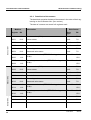
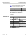
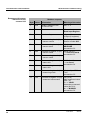
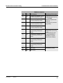
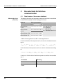
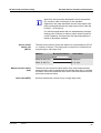
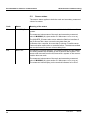
1
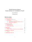
OPERATIONS MANUAL ba76148e01 IQ SENSOR NET Field bus linking LINKING THE IQ S ENSOR N ET TO A FIELD BUS 06/2013 Field bus linking For the most recent version of the manual, please visit www.ysi.com. Contact Copyright 2 YSI 1725 Brannum Lane Yellow Springs, OH 45387 USA Tel: +1 937-767-7241 800-765-4974 Email: [email protected] Internet: www.ysi.com © 2013 Xylem Inc. ba76148e01 06/2013 Field bus linking Contents IQ SENSOR NET Field bus linking Contents 1 Linking the IQ SENSOR NET to a field bus . . . . . . . . . . . . 3 1.1 1.2 2 3.2 3.3 3.4 3.5 3.6 4.2 06/2013 4 Installing the RS485 interface . . . . . . . . . . . . . . . . . . . . . Installing the Ethernet interface . . . . . . . . . . . . . . . . . . . . 2.2.1 Communication via Ethernet . . . . . . . . . . . . . . . . 2.2.2 Ethernet connection in case of indoor installation 2.2.3 Ethernet connection in case of outdoor installation ........................... 5 9 9 9 9 Configuring the IQ SENSOR NET for Profibus . . . . . . . . . 3.1.1 Setting the PROFIBUS address . . . . . . . . . . . . 3.1.2 GSD file . . . . . . . . . . . . . . . . . . . . . . . . . . . . . . . Configuring the IQ SENSOR NET for Modbus RTU . . . . . 3.2.1 Setting the Modbus interface parameters . . . . . PROFIBUS / Modbus RTU checklist . . . . . . . . . . . . . . . Configuring the IQ SENSOR NET for Ethernet field buses 3.4.1 GSD file for Profinet . . . . . . . . . . . . . . . . . . . . . 3.4.2 EDS file for Ethernet-IP . . . . . . . . . . . . . . . . . . . Error elimination . . . . . . . . . . . . . . . . . . . . . . . . . . . . . . . 3.5.1 PROFIBUS error elimination . . . . . . . . . . . . . . . 3.5.2 Modbus RTU error elimination . . . . . . . . . . . . . 3.5.3 Ethernet field bus error elimination . . . . . . . . . . Assigning the sensor numbers . . . . . . . . . . . . . . . . . . . . 12 12 12 13 13 14 16 16 16 17 17 18 18 19 Communication with field buses . . . . . . . . . . . . . . . . . 21 4.1 ba76148e01 4 Configuring the IQ SENSOR NET . . . . . . . . . . . . . . . . . . 12 3.1 4 3 4 Installing the interface in the IQ SENSOR NET . . . . . . . . 5 2.1 2.2 3 Interfaces of the IQ SENSOR NET . . . . . . . . . . . . . . . . . . . Linking the IQ SENSOR NET . . . . . . . . . . . . . . . . . . . . . . . 1.2.1 Linking the IQ SENSOR NET via the RS485 interface ............................. 1.2.2 Linking the IQ SENSOR NET via the Ethernet interface . . . . . . . . . . . . . . . . . . . . . . . . . . . . . . . Communication with Profibus, Profinet, Ethernet IP . . . 4.1.1 Data transmission . . . . . . . . . . . . . . . . . . . . . . . 4.1.2 Query format (output data of the PLC) . . . . . . . 4.1.3 Data block of the sensors (input data of the PLC) ............................ 4.1.4 Example . . . . . . . . . . . . . . . . . . . . . . . . . . . . . . Communication with Modbus RTU, Modbus TCP . . . . . 21 21 22 23 24 25 0-1 Contents IQ SENSOR NET Field bus linking 4.2.1 4.2.2 4.2.3 4.2.4 5 25 25 26 27 Encoded data for field bus communication . . . . . . . . 30 5.1 5.2 5.3 5.4 5.5 5.6 0-2 Data transmission . . . . . . . . . . . . . . . . . . . . . . . Query format . . . . . . . . . . . . . . . . . . . . . . . . . . . Data block of the sensors . . . . . . . . . . . . . . . . . Example . . . . . . . . . . . . . . . . . . . . . . . . . . . . . . . Data formats of the sensor datablock . . . . . . . . . . . . . . . Sensor status . . . . . . . . . . . . . . . . . . . . . . . . . . . . . . . . . Sensor model . . . . . . . . . . . . . . . . . . . . . . . . . . . . . . . . . Status info of sensors . . . . . . . . . . . . . . . . . . . . . . . . . . . Measuring mode . . . . . . . . . . . . . . . . . . . . . . . . . . . . . . . Measured value status . . . . . . . . . . . . . . . . . . . . . . . . . . ba76148e01 30 32 34 36 38 40 06/2013 IQ SENSOR NET Field bus linking Linking the IQ SENSOR NET to a field bus 1 Linking the IQ SENSOR NET to a field bus 1.1 Interfaces of the IQ SENSOR NET The IQ SENSOR NET system provides interfaces for the following networks: Field bus Interface type IQ SENSOR NET components with interfaces Modbus RTU RS485 XX-MOD Profibus Modbus TCP XX-PR Ethernet MIQ/MC2(-XX) Profinet Ethernet/IP ba76148e01 06/2013 3 Linking the IQ SENSOR NET to a field bus IQ SENSOR NET Field bus linking 1.2 Linking the IQ SENSOR NET 1.2.1 Linking the IQ SENSOR NET via the RS485 interface Steps Profibus Modbus 1 Establish the physical connection 2 Configure the interface of the IQ SENSOR NET section 3.1 section 3.2 3 Program the queries and access authorization * section 4.1 section 4.2 4 section 2.1 GSD file section 3.1.2 section 5 ff Interpret the data of the IQ SENSOR NET * Configuring the order of the sensors in the IQ SENSOR NET (see section 3.6) 1.2.2 Linking the IQ SENSOR NET via the Ethernet interface Steps Ethernet IP Profinet 1 Establish the physical connection section 2.2 2 Configure the interface of the IQ SENSOR NET section 3.4 3 Program the queries and access authorization * 4 Interpret the data of the IQ SENSOR NET section 4.1 EDS file section 3.4.2 Modbus TCP section 4.2 GSD file section 3.4.1 section 5 ff * Configuring the order of the sensors in the IQ SENSOR NET (see section 3.6) 4 ba76148e01 06/2013 IQ SENSOR NET Field bus linking Installing the interface in the IQ SENSOR NET 2 Installing the interface in the IQ SENSOR NET 2.1 Installing the RS485 interface Profibus and Modbus use the same interface (RS485) for data exchange. We especially recommend the "Aufbaurichtlinie PROFIBUS/FMS", published by the PROFIBUS user organization PNO, (PNO order number 2.111) with many practical tips for installation that also apply to Modbus systems (http://www.profibus.com/download/installation-guide/). Further instructions for the installation and operation of a Modbus network are availabe on the Internet under www.modbus.org. Detailed information on the subject of PROFIBUS is given on the Internet by the PROFIBUS user organization (PNO) under www.profibus.com. Connecting the Profibus / Modbus cable Suitable cables Connectors to be used The Profibus / Modbus cable is connected to the IQ SENSOR NET using a 9-pin D-SUB connector on the top of the housing. Field bus type Cable Profibus PROFIBUS cable Modbus Cable for RS485 (e.g. PROFIBUS cable) Manufacturer Type Phoenix Contact GmbH & Co. KG Flachsmarkt 8 32825 Blomberg Germany http://www.phoenixcontact.com VS-09-PROFB-SC (Phoenix article no. 1654549, with screwed contacts, available from YSI under the order no. 902 888Y) VS-09-PROFB-SP (Phoenix article no. 1654345, with spring contacts) To remove the blind plug, lift the safety bracket with a suitable screw driver at both clamps on the left and right side (see Fig. 2-1). ba76148e01 06/2013 5 Installing the interface in the IQ SENSOR NET IQ SENSOR NET Field bus linking 1 1 Safety bracket OK er Pow Fig. 2-1 ! Removing the safety bracket Caution If water gets into the enclosure of a module with internal power supply, there is danger of an electric shock. If water gets into the enclosure of an MIQ module, there is a risk of short circuits. To prevent the enclosures of the IQ SENSOR NET from being penetrated by water the following must be observed: Follow the safety instructions of the IQ SENSOR NET system operating manual. Use connectors recommended by YSI only. When the connector is removed, the connection socket of the IQ SENSOR NET must be closed with the blind plug and secured with the safety bracket. 6 ba76148e01 06/2013 IQ SENSOR NET Field bus linking Installing the interface in the IQ SENSOR NET Mounting the Phoenix connector DIQ/S 182 - MOD or PR approx. 100 mm M C MIQ/(MC)2 - MOD approx. 100 mm MIQ/(MC)2 - PR approx. 100 mm S OK ESC Fig. 2-2 ba76148e01 06/2013 IQ SENSOR NET modules with Phoenix connector 7 Installing the interface in the IQ SENSOR NET IQ SENSOR NET Field bus linking Phoenix connector IQ SENSOR NET instrument Wire (color*) Pin Red Terminals 1B and 2B Potential at instrument connector 1 - 2 - 3 B line Positive RxD/TxD according to RS 485 specification 4 RTS Request To Send 5 GND BUS Reference potential for data wires and terminating resistors 6 +5 V BUS Supply voltage for terminating resistors 7 Green 1A and 2A Function 8 9 A line Negative RxD/TxD according to RS 485 specification - * Wire colors when using a standard PROFIBUS cable. Please observe the operating manual of the connector. 8 ba76148e01 06/2013 IQ SENSOR NET Field bus linking Installing the interface in the IQ SENSOR NET 2.2 Installing the Ethernet interface The IQ SENSOR NET system can be linked to a LAN through the MIQ/MC2 controller. Basic knowledge of network engineering is helpful when establishing a local network. Depending on the network configuration, several settings have to be made on the individual network components. Settings that concern network components from third-party manufacturers (such as the router) are only referred to in general here. Detailed information on in which menus the settings should be done are given in the respective operating manual of your instrument. If you have no network knowledge, please contact your network administrator. Profinet, Modbus TCP and Ethernet IP use the same interface (Ethernet) and the same cable type (Ethernet) for data exchange. 2.2.1 Communication via Ethernet The IQ SENSOR NET provides an interface for Fast Ethernet (100 MBit/s). If configured as a DHCP client, the IQ SENSOR NET can automatically get its IP settings from a DHCP server in the network. 2.2.2 Ethernet connection in case of indoor installation The Ethernet cable is connected to the IQ SENSOR NET with the RJ45 connector on the underside of the enclosure of the MIQ/MC2 controller. 2.2.3 Ethernet connection in case of outdoor installation When plugged in, the RJ45 socket is not sufficiently protected against moisture. With outdoor installation, the Ethernet cable must therefore be clamped directly on the PCB of the MIQ/MC2 controller to ensure a safe Ethernet communication. For this purpose there is a 4-pole terminal strip and a shielding terminal on the main PCB. An LSA punch down tool is required for the assembly. ba76148e01 06/2013 9 Installing the interface in the IQ SENSOR NET Connecting the Ethernet cable with the main PCB IQ SENSOR NET Field bus linking 1 Open the MIQ module. 2 Disconnect the flat flexible cable (pos. 1 in Fig. 2-3) from the main PCB. 1 Fig. 2-3 10 2 Ethernet connection with RJ45 socket 3 Unscrew the RJ45 socket enclosure (pos. 2 in Fig. 2-3). 4 Screw a cable gland with sealing ring into the free duct. Then loosen the cap nut of the cable gland. ba76148e01 06/2013 IQ SENSOR NET Field bus linking Installing the interface in the IQ SENSOR NET LSA terminal strip X10 X9 X8 X7 Rx- Rx+ Tx- Tx+ SHIELD CLAMP ENTHERNET CABLE 4 3 Fig. 2-4 ba76148e01 06/2013 Ethernet connection via terminal strip 5 Strip the Ethernet cable for approx. 2 cm and untwist the Rx+, Rx-, Tx+ and Tx wires. 6 Carefully slash the cable shield (foil + netting) lengthwise and put it backwards over the cable sheath (pos. 3 in Fig. 2-4). 7 Feed the Ethernet cable through the cable gland into the module housing. 8 Where the cable shield was put backwards, press the Ethernet cable into the shielding terminal (pos. 4 in Fig. 2-4). The shielding terminal must contact the cable shield across a wide area. 9 Connect the Rx+, Rx-, Tx+ and Tx- wires to the LSA terminal strip with the aid of an LSA punch down tool. Make sure that the cable assignment agrees with the specification on the terminal label under the terminal strip. 10 Fasten the cap nut of the screwed cable gland. 11 Close the module. 11 Configuring the IQ SENSOR NET Opening the setting menu for Profibus Settings IQ SENSOR NET Field bus linking 3 Configuring the IQ SENSOR NET 3.1 Configuring the IQ SENSOR NET for Profibus 3.1.1 Setting the PROFIBUS address 1 Open the setting menu with <S>. 2 For MIQ/MC2: Press <> and <OK> to select and confirm the menu item, Settings of bus interfaces 3 Select and confirm the bus interface with <> and <OK>. Setting Selection/Values Explanation Device Address 1 ... 126 Instrument address of the IQ SENSOR NET in the Profibus 4 Edit the settings. To accept all settings, you have to highlight the Save and quit menu item at the lower end of the setting table and to confirm with <OK>. If you exit the setting table via <M>, <ESC>/Quit or the Quit menu item, all changes are ignored. 3.1.2 GSD file The GSD file contains all necessary information on the Profibus module and is required by the configuration program of the Profibus master. The current GSD file is provided on the Internet under www.WTW.com. 12 ba76148e01 06/2013 IQ SENSOR NET Field bus linking Opening the setting menu for Modbus RTU Configuring the IQ SENSOR NET 3.2 Configuring the IQ SENSOR NET for Modbus RTU 3.2.1 Setting the Modbus interface parameters 1 Open the setting menu with <S>. 2 For MIQ/MC2: Press <> and <OK> to select and confirm the menu item, Settings of bus interfaces 3 Select and confirm the bus interface with <> and <OK>. Settings Setting Selection/Values Explanation Device Address 1 ... 247 Instrument address of the IQ SENSOR NET in the Modbus RTU Baud rate 1200 2400 4800 9600 19200 38400 57600 Baud rate Parity None Even Odd Parity 4 None (2 stop bits) Even (1 stop bit) Odd (1 stop bit) Edit the settings. To accept all settings, you have to highlight the Save and quit menu item at the lower end of the setting table and to confirm with <OK>. If you exit the setting table via <M>, <ESC>/Quit or the Quit menu item, all changes are ignored. ba76148e01 06/2013 13 Configuring the IQ SENSOR NET IQ SENSOR NET Field bus linking 3.3 PROFIBUS / Modbus RTU checklist The following checklist supports you when planning, projecting and installing a PROFIBUS or Modbus RTU system with the IQ SENSOR NET. For smooth operation, you should be able to answer all questions with "Yes". Is the [bus system] (bus segment) installed without branch lines? Was the correct cable used (e.g. PROFIBUS cable, see section 2.1)? Are the poles of the signal lines A line and B line correctly connected at all bus connections? Is it guaranteed that there is no short-circuit between A line, B line and cable shielding? Is the shielding installed free of interruptions? Are the guidelines for shielding and grounding being observed, and doesn't any unallowed potential equalization current flow via the shielding? Is the maximum cable length (per bus segment) observed for the corresponding baud rate? Do all devices support the required baud rate? Only for Profibus: With 12 Mbit/s transmission rate only: Are the bus plugs suitable for this baud rate? Are exactly two terminators switched on at the ends of the [bus system] (bus segment)? Are the terminators supplied with voltage so the following applies: UB line - UA line > + 500 mV? Do all devices have individual bus addresses? After changing the bus address, have the devices been restarted (switched off and on again)? Note: The IQ SENSOR NET does not have to be restarted. Do the addresses projected in the master correspond to the actual addresses? Are all addresses less than or equal to the parameter HSA and less than 126 (HSA = Highest Station Address)? Only for Profibus: Is the currently valid GSD being used? If you are in doubt, download it from the Internet. Only for Profibus: Have admissible bus parameters been set only? If you are in doubt set them to default values. 14 ba76148e01 06/2013 IQ SENSOR NET Field bus linking Configuring the IQ SENSOR NET Is it guaranteed that the Profibus or Modbus master has consistent access to the 16 byte sensor data structure? After commissioning: Do all devices signal error-free behavior? (IQ SENSOR NET: status "Online" in the measured value and status display). For consistent access with Siemens PLC with programming language STEP7, the following commands have to be used: – SFC15 (for writing) – SFC14 (for reading) ba76148e01 06/2013 15 Configuring the IQ SENSOR NET IQ SENSOR NET Field bus linking 3.4 Configuring the IQ SENSOR NET for Ethernet field buses Setting Selection/Values Explanation DHCP Yes The IQ SENSOR NET is configured as a DHCP client. If a DHCP server is in the network, the IQ SENSOR NET receives all other network settings from the DHCP server. No The IQ SENSOR NET is not configured as a DHCP client. All other settings have to be done as required. IP address Address Permanent IP address for the IQ SENSOR NET in the LAN (if DHCP No). Subnet mask Address Subnet mask (if DHCP No). The subnet mask depends on the network size (for small networks: e.g. 255.255.255.0). DNS server Address Entry for field bus not required. For a connection with the Internet (if DHCP No), e.g.: IP address of the DNS server in the network Entry of IP address or e.g. 127.0.0.1 Standard gateway Address Entry for field bus not required. For a connection with the Internet (if DHCP No), e.g.: IP address of the instrument establishing the access to the Internet Entry of IP address or e.g. 127.0.0.1 3.4.1 GSD file for Profinet The GSD file contains all necessary information on the Profinet module and is required by the configuration program for the Profinet master. The current GSD file is provided on the Internet under www.WTW.com. 3.4.2 EDS file for Ethernet-IP The EDS file contains information on the Ethernet-IP module. It is evaluated by some configuration programs. The current EDS file is provided on the Internet under www.WTW.com. 16 ba76148e01 06/2013 IQ SENSOR NET Field bus linking Configuring the IQ SENSOR NET 3.5 Error elimination Here you will find causes and actions to take of errors concerning the PROFIBUS and Modbus communication only. General errors of the IQ SENSOR NET system are dealt with in chapter 10 WHAT TO DO IF.... 3.5.1 Data transmission between the bus master and IQ SENSOR NET is faulty PROFIBUS error elimination Cause Remedy – Incorrect wiring – Check/change the connections (see section ) – Use checklist according to section 3.3 – Incorrect setting of the address – Check/change the setting of the address (see section 3.2.1) – Incorrect protocol – Check the version of the GSD file – Adapt the protocol The PLC does not contain any plausible input data ba76148e01 06/2013 – IQ SENSOR NET defective – Send IQ SENSOR NET to YSI Cause Remedy – Input data and output data are not consistent – When programming the PLC, define input data and output data as consistent over the entire data length – The data interpretation of the PLC is not correct – Observe the data alignment of the PLC data representation. If necessary, exchange the high-order and low-order bytes word by word 17 Configuring the IQ SENSOR NET IQ SENSOR NET Field bus linking 3.5.2 Data transmission between the bus master and IQ SENSOR NET is faulty Modbus RTU error elimination Cause Remedy – Incorrect wiring – Check/change the connections (see section ) – Use checklist according to section 3.3 The PLC does not contain any plausible input data – Incorrect setting of address, baud rate, parity – Check/change the settings (see section 3.2.1) – Incorrect protocol – Adapt the protocol – Controller of the IQ SENSOR NET defective – Return the controller to YSI Cause Remedy – The data interpretation is not correct – Heed the data formats of the IQ SENSOR NET (see also section 4.1.3). 3.5.3 No network connection Ethernet field bus error elimination Cause Remedy – Ethernet hardware defective, e.g. – Open the MIQ/MC2 and check the red Ethernet LED. – Ethernet cable defective – Ethernet connection to MIQ/MC2 – Switch or router to which the IQS is connected is defective – The red Ethernet LED is not illuminated (hardware defective): Use other hardware, e.g.: Ethernet cable, Ethernet connector on the router, router – The red Ethernet LED is illuminated (hardware OK): Check for other errors (see below) – Wrong setting in the IQ SENSOR NET (system/TCP/IP settings menu) 18 – Correct the settings (e.g. DHCP yes, but no network addresses displayed) ba76148e01 06/2013 IQ SENSOR NET Field bus linking The PLC does not contain any plausible input data Configuring the IQ SENSOR NET Cause Remedy – Wrong setting in the router/switch – Correct the settings – Blocking by firewall – Contact your network administrator or a network specialist Cause Remedy – Input data and output data are not consistent – When programming the PLC, define input data and output data as consistent over the entire data length – The data interpretation of the PLC is not correct – Heed the data formats of the IQ SENSOR NET (see also section 4.1.3). – Observe the data alignment of the PLC data representation. If necessary, exchange the high-order and low-order bytes word by word 3.6 Assigning the sensor numbers The basis for data transmission between the superordinate control system (PLC) and the IQ SENSOR NET is formed by the unique assignment of a sensor to its sensor number (Sxx) in the IQ SENSOR NET system. During the initial commissioning, the sensor numbers are assigned by the system in the order in which the sensors are recognized by the system. Preparation of the IQ SENSOR NET for communication with a field bus may require, e.g. the following: Creating an IQ SENSOR NET system with specific assignment of sensor numbers to sensors Creating several IQ SENSOR NET systems with the identical assignment of sensor numbers to sensors Changing the order of the sensors in an already installed system Creating the assignment of sensor numbers ba76148e01 06/2013 You want to install an IQ SENSOR NET system and, at the same time, to create a specific sequence of sensor number assignments to the sensors. 19 Configuring the IQ SENSOR NET Changing the assignment of sensor numbers IQ SENSOR NET Field bus linking 1 Carry out a system start without any sensors (see system operating manual). 2 Connect the sensors to the system in the required order. After connecting each sensor, wait until the sensor is recognized by the system (see system operating manual, chapter Installation). You want to change the assignment of sensor numbers to the sensors in an already running IQ SENSOR NET system. 1 Unplug all sensors from the IQ SENSOR NET. When the inactive datasets are deleted, all settings for the sensors are deleted as well. Creating the identical assignment of sensor numbers in several systems 2 Delete all inactive datasets in the list of sensors (see System operating manual, chapter Deleting inactive datasets of sensors). 3 Connect the sensors to the system in the required order. After connecting a sensor, wait until the sensor is recognized by the system (see system operating manual, chapter Installation). You want to install several identical IQ SENSOR NET systems and, at the same time, to create the same sequence of sensor number assignments to the sensors in all systems. 1 20 Copy the configuration to a further controller from the original one (see IQS Connect: ConfigSaveLoad). ba76148e01 06/2013 IQ SENSOR NET Field bus linking Communication with field buses 4 Communication with field buses The IQ SENSOR NET monitors the current state of each sensor operated on the system. The sensor status documents sensor information (measured value status and status info of the sensor) and current processes (e.g. calibration or cleaning). The sensor status is superordinate to the measured value status. The influence of the sensor status on the measured value is documented with the status descriptions. For the measured value to be evaluated, e.g. by a superordinate control system such as PLC, the sensor status and measured value status also have to be taken into account together with the measured value. A measured value is suitable for further evaluation if both of the following conditions are met: 1st Sensor status MEASURE 2nd Measured value status VALID 4.1 Communication with Profibus, Profinet, Ethernet IP 4.1.1 Data transmission The sensor number (Sxx) is the identification for a sensor. The sensor number is always transmitted in the first byte of the output and input data. Thus the control system (PLC) can clearly query data of individual sensors. The data is transferred cyclically in two steps: Output data of the PLC: The superordinate control system (PLC) sends a prompt to the IQ SENSOR NET to provide data of the sensor with a certain sensor number. Input data of the PLC: The IQ SENSOR NET checks whether the prompted sensor number is available and returns the data of the sensor with the relevant sensor number to the superordinate control system (PLC). ba76148e01 06/2013 21 Communication with field buses IQ SENSOR NET Field bus linking Start Output data in PLC: Assign a sensor number (Sxx) to a sensor Input data in PLC: Data from IQ SensorNet Is the sensor number identical in the output data and input data ? no Process the data of the sensor Query the data of another sensor with different sensor number? Fig. 4-1 4.1.2 no Data transmission in (Profinet, Profibus, Ethernet IP) Query format (output data of the PLC) 1 Byte - from the superordinate control system (PLC) to the IQ SENSOR NET For Ethernet IP: Instance ID= 101 (SensorSelector) Address Offset 0h 22 Information Sensor number (Sxx) in the IQ SENSOR NET Data format Data type Bit Int 8 7-0 ba76148e01 06/2013 IQ SENSOR NET Field bus linking Communication with field buses 4.1.3 Data block of the sensors (input data of the PLC) 16 bytes - from the IQ SENSOR NET to the superordinate control system (PLC) For Ethernet IP: Instance ID =102 (SensorData) Address Information Data format Data type Bit Offset 0h Sensor number Int 8 7-0 Offset 1h Sensor status Int 8 7-0 Offset 2h Sensor model Int 16 15-8 Offset 3h Offset 4h 7-0 Status info Int 16 Offset 5h 7-0 Offset 6h Measuring mode Int 8 7-0 Offset 7h Status of main measured value Int 8 7-4 Status of secondary measured value Offset 8h Offset 9h Main measured value (IEEE-754 floating point, 32-bit) 3-0 Float 32 31-24 23-16 Offset Ah 16-8 Offset Bh 7-0 Offset Ch Offset Dh ba76148e01 15-8 Secondary measured value (IEEE-754 floating point, 32-bit) Float 32 31-24 23-16 Offset Eh 16-8 Offset Fh 7-0 06/2013 23 Communication with field buses IQ SENSOR NET Field bus linking 4.1.4 Example Sensor data 24 Byte Value Information Meaning of the value Offset 0h 02h Sensor number 02h (Int 8) --> 2 Sensor number S02 Offset 1h 02h Sensor status 02h (Int 8) --> MEASURE see section 5.2 Offset 2h 04h Sensor model Offset 3h 01h Sensor model 0401h (Int 16) --> VisoTurb 700 IQ see section 5.3 Offset 4h 00h Status info Offset 5h 00h Status info Offset 6h 00h Measuring mode 00h (Int 8) --> FNU Turb see section 5.5 Offset 7h 14h Measured value status 14h (Int 8) Main measured value (bits 7-4): 1h --> VALID Secondary measured value (bits 3-0): 4h --> MISSING see section 5.6 Offset 8h 42h Offset 9h 9Eh Main measured value Offset Ah 46h Offset Bh C2h 429E46C2h (Float 32) --> 79,1382 Measured parameter and unit, see byte 10 (measuring mode) Offset Ch 00h Offset Dh 00h Secondary measured value Offset Eh 00h Offset Fh 00h 00000000h (Float 32) --> 0 but measured value invalid (MISSING), see byte 11 (measured value status) 0000h (Int 16) --> no errors see section 5.4 ba76148e01 06/2013 IQ SENSOR NET Field bus linking Communication with field buses 4.2 Communication with Modbus RTU, Modbus TCP 4.2.1 Data transmission On each query of sensor data with the Modbus protocol, a block of consecutive registers is read. Query and response telegram Data transmission takes place via query and response telegrams. The form of the telegrams is determined by the Modbus RTU protocol. The Modbus master transmits a query telegram with a Modbus command to the Modbus slave (here, the IQ SENSOR NET). The Modbus slave transmits a response telegram with the requested data or an error message. 4.2.2 Supported Modbus commands Query format The IQ SENSOR NET provides the data block for read access only. Writing Modbus commands are not carried out. The following commands are available: Modbus commands Command code Read Input Register 04h Read Holding Register 03h For a query of sensor data, determine the first register and the number of registers to be read. Determining the first register to be read The first register to be read depends on the sensor number (Sxx): R = [(Sxx - 1) * 8] + 1. Example: Determine the first register with data block for the sensor S02: R = [(2 - 1) * 8] + 1 = 9 The number of registers to be read for one sensor data block is 8 registers. With one Modbus query, up to 125 registers (15 data blocks) can be read. ba76148e01 06/2013 25 Communication with field buses IQ SENSOR NET Field bus linking 4.2.3 Data block of the sensors The data block contains the data of the sensors in the order of their registering on the IQ SENSOR NET (Sxx number). The data of a sensor are stored in 8 registers each. Modbus Sensor S03 ... Sensor S02 Sensor S01 Register 26 Information Bit Data format Data type Bit 0001 1-8 Sensor number (S01) Int 8 7-0 0001 9-16 Sensor status Int 8 7-0 0002 1-16 Sensor model Int 16 15-0 0003 1-16 Status info Int 16 15-0 0004 1-8 Measuring mode Int 8 7-0 0004 9-16 Measured value status Int 8 7-0 0005 1-16 Float 32 31-16 0006 1-16 Main measured value (IEEE-754 floating point, 32-bit) 0007 1-16 Float 32 0008 1-16 Secondary measured value (IEEE-754 floating point, 32-bit) 0009 1-8 Sensor number (S02) Int 8 7-0 0009 9-16 Sensor status Int 8 7-0 0010 1-16 Sensor model Int 16 15-0 0011 1-16 Status info Int 16 15-0 0012 1-8 Measuring mode Int 8 7-0 0012 9-16 Measured value status Int 8 7-0 0013 1-16 Float 32 31-16 0014 1-16 Main measured value (IEEE-754 floating point, 32-bit) 0015 1-16 Float 32 0016 1-16 Secondary measured value (IEEE-754 floating point, 32-bit) 0017 1-8 Int 8 7-0 0018 9-16 Int 8 7-0 ... ... ... ... ... 15-0 31-16 15-0 15-0 31-16 15-0 ba76148e01 06/2013 IQ SENSOR NET Field bus linking Communication with field buses The counting method of the Modbus registers and Modbus bits and the allocation of MSB and LSB is different from the usual method of most programming languages. Modbus Usually Count start of the register 1 0 MSB* allocation of the register Bit 1 Bit 15 LSB* allocation of the register Bit 16 Bit 0 * MSB = Most significant bit, LSB = Least significant bit 4.2.4 Query of the sensor data block for sensor S02 ba76148e01 06/2013 Example Modbus query Byte Value Information Meaning of the value 1 01h Modbus address of the IQ SENSOR NET 01h --> 1 2 04h Function 04h --> 4 Read Input Register see section 4.2.2 3 00h Start address HI 4 08h Start address LO 0008h --> 8 Start with register 9 (Modbus counting method) 5 00h Number of HI registers 0008h --> 8 8 registers 6 08h Number of LO registers 7 70h CRC (HI) 8 0Eh CRC (LO) Checksum (CRC) 27 Communication with field buses Response with sensor data block of the sensors S02 28 IQ SENSOR NET Field bus linking Modbus response Byte Value Information Meaning of the value 1 01h Modbus address of the IQ SENSOR NET 01h --> 1 2 04h Function 04h --> 4 Read Input Register 3 10h Number of bytes 10h --> 16 16 Byte (8 registers) 4 02h Contents of register 9 (HI) = sensor number 02h (Int 8) --> 2 Sensor number S02 5 02h Contents of register 9 (LO) = sensor status 02h (Int 8) --> MEASURE see section 5.2 6 04h Contents of register 10 (HI) = sensor model 7 01h Contents of register 10 (LO) = sensor model 0401h (Int 16) --> VisoTurb 700 IQ see section 5.3 8 00h Contents of register 11 (HI) = status info 9 00h Contents of register 11 (LO) = status info 10 00h Contents of register 12 (HI) = measuring mode 00h (Int 8) --> FNU Turb see section 5.5 11 14h Contents of register 12 (LO) = measured value status 14h (Int 8) Main measured value (bits 7-4): 1h --> VALID Secondary measured value (bits 3-0): 4h --> MISSING see section 5.6 0000h (Int 16) --> no errors see section 5.4 ba76148e01 06/2013 IQ SENSOR NET Field bus linking Communication with field buses Modbus response ba76148e01 06/2013 Byte Value Information 12 42h Contents of register 13 (HI) = main measured value 13 9Eh Contents of register 13 (LO) = main measured value 14 46h Contents of register 14 (HI) = main measured value 15 C2h Contents of register 14 (LO) = main measured value 16 00h Contents of register 15 (HI) = secondary measured value 17 00h Contents of register 15 (LO) = secondary measured value 18 00h Contents of register 16 (HI) = secondary measured value 19 00h Contents of register 16 (LO) = secondary measured value 20 23h CRC (HI) 21 5Eh CRC (LO) Meaning of the value 429E46C2h (Float 32) --> 79,1382 Measured parameter and unit, see byte 10 (measuring mode) 00000000h (Float 32) --> 0 but measured value invalid (MISSING), see Byte 11 (measured value status) Checksum (CRC) 29 Encoded data for field bus communication Measured values (Float 32) IQ SENSOR NET Field bus linking 5 Encoded data for field bus communication 5.1 Data formats of the sensor datablock The data for the main and secondary measured values are transmitted in the IEE-754 standard 32-bit floating point format. Address Bit representation MSB* Offset 0h bits 31-24 Offset 1h bits 23-16 LSB* S = sign (bit 31) E = exponent (bits 30-23) E M M M M M M M M = mantissa (bits 22-0) S E E E E E E E Offset 2h bits 15-8 M M M M M M M M Offset 3h bits 7-0 M M M M M M M M * MSB = Most significant bit, LSB = Least significant bit If not all of the bits of the exponent are 0, the value is calculated according to: V = −1S ⋅ 2 E −127 ⋅ (1 + M b 22 ⋅ 2 −1 + M b 21 ⋅ 2 −2 + M b 20 ⋅ 2 −3 + ... + M b 0 ⋅ 2 −23 ) If all of the bits of the exponent are 0, the value is calculated according to: V = −1S ⋅ 2 −126 ⋅ ( M b 22 ⋅ 2 −1 + M b 21 ⋅ 2 −2 + M b 20 ⋅ 2 −3 + ... + M b 0 ⋅ 2 −23 ) A value is 0 if all the bits of both the exponent as well as the mantissa are 0. Evaluation 30 Meaning Measured value 0 Check the measured value status Measured value status <> 1 The measured value is invalid (error) ba76148e01 06/2013 IQ SENSOR NET Field bus linking Encoded data for field bus communication Apart from the byte order described in the bit representation, another order of the bytes is also possible. Opposite to the order described, the two lower bytes have been exchanged with the two upper bytes in this order (b4 b3 b2 b1 - b2 b1 b4 b3). For field bus applications that can independently interpret floating point numbers (or allow to select a data format for certain registers), the byte order the data interpretation is based on should be checked. Sensor model Status info (INT16) The data for the sensor model and status info is transmitted as INT16, i.e. consists of 2 bytes. The assignment is carried out in Motorola format (the higher value byte first). Address Bit representation MSB Measured value status (Int8) Other data (INT8) ba76148e01 06/2013 Information LSB Offset 0h bits 15-8 High byte Offset 1h bits 7-0 Low byte The data for the measured value status of the main and secondary measured values are encoded jointly into a single byte. Bits 7-4 encode the status of the main measured value, bits 3-0 encode the status of the secondary measured value. All other data always consist of only a single byte (Int8). 31 Encoded data for field bus communication 5.2 IQ SENSOR NET Field bus linking Sensor status The sensor status applies to both the main and secondary measured value of a sensor. Code Status Meaning of the status 00h UNUSED_ID Sensor and sensor number are not available in the IQ SENSOR NET system. The measured value status of the main and secondary measured value is MISSING (4h) (see section 5.6 MEASURED VALUE STATUS). The UNUSED_ID status also occurs when the field bus interface of the IQ SENSOR NET does not receive any data from the IQ SENSOR NET controller for more than 2 minutes. Possible cause: Communication malfunction or controller failure. The data transmitted last remain frozen for the two minutes delay time. 01h INACTIVE The sensor is currently inactive. The sensor number (ID) and respective setting dataset are available in the IQ SENSOR NET system. The sensor was removed from the IQ SENSOR NET system or the communication does not work. The measured value status of the main and secondary measured value is MISSING (4h) (see section 5.6 MEASURED VALUE STATUS). The measured value display on the terminal indicates Init or Error. 32 ba76148e01 06/2013 IQ SENSOR NET Field bus linking Encoded data for field bus communication Code Status Meaning of the status 02h MEASURE The sensor is in measuring mode. The measured value status can be VALID, OFL or INVALID. The measured value display on the terminal indicates the valid measured value, OFL or "----" (invalid measured value). For the measured value to be evaluated, e.g. by a superordinate control system, the sensor status and measured value status also have to be taken into account together with the measured value (see also section 5.6 MEASURED VALUE STATUS) 03h CALIBRATE The sensor is being calibrated. No measured value is available. The measured value status of the main and secondary measured value is MISSING (4h) (see section 5.6 MEASURED VALUE STATUS). The measured value display on the terminal indicates Cal. 04h ERROR The sensor is in a serious error status. 05h MAINTENANCE The sensor is in maintenance condition or a cleaning cycle (cleaning including adjustment phase) is active. The measured value display on the terminal shows a flashing measured value or Clean. The measured value and measured value status are frozen while the sensor is in the MAINTENANCE condition. In the case of the measured value status VALID, the measured value is frozen with the value displayed at the start of the MAINTENANCE status. ba76148e01 06/2013 33 Encoded data for field bus communication 5.3 IQ SENSOR NET Field bus linking Sensor model The sensor model is the model name the sensor registers with on the IQ SENSOR NET. 34 Code Model 0101h SensoLyt700IQ 0201h TetraCon700IQ 0301h TriOxmatic700IQ 0302h TriOxmatic701IQ 0303h TriOxmatic702IQ 0304h SC FDO 700 (FDO700IQ) 0305h SC FDO 701 (FDO700IQ) 0401h VisoTurb700IQ 0402h ViSolid700IQ 0501h AmmoLyt700IQ 0503h AmmoLyt+ (AmmoLyt+700IQ) 0907h AmmoLyt+K (AmmoLyt+700IQ) 0601h NitraLyt700IQ 0602h NitraLyt+ (NitraLyt+700IQ) 0701h NitraVis700/1IQ 0702h NitraVis700/5IQ 0703h CarboVis700/5IQ 0704h SolidVis700IQ (UV/VIS sensors with TSS option) 0705h NitraVis700/5IQ (NiCaVis700IQ) 0706h CarboVis700/5IQ (NiCaVis700IQ) 0707h CarboVis700/1IQ 0801h MIQ/IC2, current input 1 0802h MIQ/IC2, current input 2 0901h VARiON A (VARiON700IQ) 0902h VARiON N (VARiON700IQ) 0905h VARiON A (VARiON+700IQ) ba76148e01 06/2013 IQ SENSOR NET Field bus linking ba76148e01 06/2013 Encoded data for field bus communication Code Model 0906h VARiON N (VARiON+700IQ) 0907h VARiON K (VARiON+700IQ) 0A01h NitraVis701 IQ (+ NiCaVis701IQ NI) 0A02h NitraVis705 IQ (+ NiCaVis705IQ + NiCaVis705IQ NI) 0A03h CarboVis701 IQ (+ NiCaVis701IQ NI) 0A04h CarboVis705 IQ (+ NiCaVis705IQ + NiCaVis705IQ NI) 0A07h SolidVis701 IQ (UV/VIS sensors with TSS option) 0A08h SolidVis705 IQ (UV/VIS sensors with TSS option) 0A1Ah Virtual N sensor - NitraVis701IQ NI 0A1Bh Virtual N sensor - NitraVis705IQ NI 0A1Ch Virtual C sensor 1 - CarboVis701 IQ 0A1Dh Virtual C sensor 2 - CarboVis701 IQ 0A1Eh Virtual C sensor 3 - CarboVis701 IQ 0A1Fh Virtual C sensor 4 - CarboVis701 IQ 0A20h Virtual C sensor 1 - CarboVis705 IQ 0A21h Virtual C sensor 2 - CarboVis705 IQ 0A22h Virtual C sensor 3 - CarboVis705 IQ 0A23h Virtual C sensor 4 - CarboVis705 IQ 0B01h P 700 IQ 0C01h IFL 700 IQ 0C02h IFL 701 IQ 35 Encoded data for field bus communication 5.4 IQ SENSOR NET Field bus linking Status info of sensors Model Bit 0 Bit 1 SensoLyt700IQ Component hardware defective SensCheck: pH electrode defective, glass broken - - - - - TetraCon700IQ Bit 2 SensReg: Electrolyte supply is depleted TriOxmatic700IQ TriOxmatic701IQ TriOxmatic702IQ Bit 3-31 SensLeck: Membrane head damaged* - - - SC FDO 700 Measurement interfered - - SC FDO 701 Measurement interfered - - VisoTurb700IQ SensCheck: Sensor contaminated ViSolid700IQ SensCheck: Ultrasound cleaning system has failed - AmmoLyt700IQ - - - AmmoLyt+ - - - AmmoLyt+K - - - NitraLyt700IQ - - - NitraLyt+ - - - NitraVis700/xIQ - - - CarboVis700/xIQ - - - SolidVis700IQ - - - NitraVis70xIQ Component hardware defective xxx Optical measuring range exceeded - CarboVis70xIQ SolidVis70xIQ - MIQ/IC2 - - - VARiON A - - - VARiON N - - - VARiON K - - - * 36 The SensLeck function is not available with the sea water model (-SW variant) ba76148e01 06/2013 IQ SENSOR NET Field bus linking Encoded data for field bus communication continued Model Bit 0 IFL 700 IQ Component hardware defective IFL 701 IQ P 700 IQ Bit 1 Bit 2 Bit 3-31 - - - - - - Liquid tank xxx almost depleted! Air bubbles in the analyzer - Note The status info must be evaluated for each bit individually. ba76148e01 06/2013 37 Encoded data for field bus communication 5.5 IQ SENSOR NET Field bus linking Measuring mode Code Model 00h 01h 02h 03h SensoLyt700IQ pH mV TetraCon700IQ S/cm SAL TriOxmatic700IQ TriOxmatic701IQ TriOxmatic702IQ mg/l O2 % O2 SC FDO 700 SC FDO 701 mg/l O2 % O2 VisoTurb700IQ FNUTurb ViSolid700IQ TDS S/m NTUTurb TEFTurb g/l TSS (M11) % TSS (M11) g/l TSS (M21) AmmoLyt700IQ AmmoLyt+ mg/l NH4-N mg/l NH4 mV AmmoLyt+K mg/l K mV NitraLyt700IQ NitraLyt+ mg/l NO3-N mg/l NO3 1 38 04h 05h mg/l SiO2 ppm SiO2 g/l TS % TSS (M21) g/l SiO2 (M11) % SiO2 (M11) 06h 07h g/l SiO2 (M21) % SiO2 (M21) 08h mV M1 = matrix type 1, M2 = matrix type 2 matrix types: see ViSolid 700 IQ sensor operating manual ba76148e01 06/2013 IQ SENSOR NET Field bus linking Encoded data for field bus communication Code Model 00h 01h 02h NitraVis700/xIQ NitraVis70xIQ mg/l NO3-N mg/l NO3 mg/l NO3-N4 NitraVis70xIQ NI mg/l NO2-N mg/l NO2 CarboVis700/xIQ CarboVis70xIQ mg/lCO Dto mg/lC ODds mg/lTO C SolidVis700IQ SolidVis70xIQ (m)g/l TSS 2 MIQ/IC2 3 VARiON A mg/l NH4-N mg/l NH4 mV VARiON N mg/l NO3-N mg/l NO3 mV VARiON K mg/l K mV P 700 IQ mg/l PO4-P mg/l PO4 IFL 70x IQ m ba76148e01 06/2013 03h 04h 05h 06h 07h 08h mg/lB OD mg/lDO C Abs/m SACto Abs/m SACds mg/l CSB4 UVT 2545 1 M1 = matrix type 1, M2 = matrix type 2 matrix types: see ViSolid 700 IQ sensor operating manual 2 The measurement unit depends on the settings of the main sensor 3 The measured parameter and measurement unit depend on the settings of the display values (see MIQ/IC2 sensor operating manual). 4 Only xxxVis700/xIQ: Test measurement with standards 5 Only CarboVis70xIQ 39 Encoded data for field bus communication 5.6 IQ SENSOR NET Field bus linking Measured value status The measured value status is available for both the main and secondary measured value of a sensor. Code Status Meaning of the status 1h VALID The measured value is valid. In the case of the sensor status MAINTENANCE, the measured value is frozen on the value of the start of the MAINTENANCE status. The measured value display of the IQ SENSOR NET shows a flashing measured value or Clean. 2h OFL The measured value lies outside the selected measuring range. The transmitted measured value is set to 0. The measured value display of the IQ SENSOR NET indicates OFL. 3h INVALID The measured value is invalid. The transmitted measured value is set to 0. The measured value display of the IQ SENSOR NET indicates "----" (invalid measured value). 4h MISSING The measured value cannot be determined or is not available. The transmitted measured value is set to 0. The measured value display of the IQ SENSOR NET indicates Cal or Error. 40 ba76148e01 06/2013 Xylem |'zīləm| 1) The tissue in plants that brings water upward from the roots; 2) a leading global water technology company. We're 12,500 people unified in a common purpose: creating innovative solutions to meet our world's water needs. Developing new technologies that will improve the way water is used, conserved, and re-used in the future is central to our work. We move, treat, analyze, and return water to the environment, and we help people use water efficiently, in their homes, buildings, factories and farms. In more than 150 countries, we have strong, long-standing relationships with customers who know us for our powerful combination of leading product brands and applications expertise, backed by a legacy of innovation. For more information on how Xylem can help you, go to www.xyleminc.com YSI 1725 Brannum Lane Yellow Springs, OH 45387 Tel: +1 937-767-7241; 800-765-4974 Fax: +1 937-767-1058 Email: [email protected] Web: www.ysi.com ©Xylem Inc