1
DC-DC Converters Power Module type
2 Connection for
Standard Use
1 Pin Connection
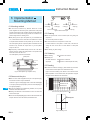
Table 1.1 Pin connection and function
NO.
Pin Connection
nIn order to use the power supply, it is necessary to wire as shown in
+DC input
-VIN
-DC input
RC1
Remote ON/OFF(Input side)
+VOUT
+DC output
-VOUT
-DC output
CB
Current balance
Reference: 4.5
VB
Voltage balance
4.6
TMP
Thermal detection signal
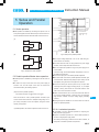
Fig.2.1 and external components in table2.1.
Adjustment of output voltage
+S
+Remote sensing
-S
-Remote sensing
IOG
Inverter operation monitor
AUX
Auxiliary power supply
FG
Mounting hole(FG)
Pin Connection
-VIN
RC1
+VOUT
-VOUT
CB
VB
TMP
RC3
RC2
TRM
+S
-S
DBS
”Remote sensing”
Avoid applying AC input directly.
It will damage the power supply.
nOperate with the conduction cooling(e.g. heat radiation from the
aluminum base plate to the attached heat sink).
Reference: 6.5
”Derating”
Heatsink
Reference
+S
F1
3.1 ”Wiring input pin”
4.5 ”Remote ON/OFF”
Cin
DC
Noise
input
filter
+VIN
+VOUT
-VIN
-VOUT
RC1 FG
3.2 ”Wiring output pin”
Load
-S
Fig.2.1 Connection for standard use
5.2 ”Parallel operation/Master-slave operation”
4.3 ”Thermal detection/Thermal protection”
4.5 ”Remote ON/OFF”
4.7 ”Adjustable voltage range”
4.6 ”Remote sensing”
IOG
4.4 ”Inverter operation monitor”
AUX
4.5 ”Remote ON/OFF”
FG
3.1 ”Wiring input pin”
TRM +S -S IOG AUX
+
Co
CY
CB VB TMP RC3 RC2
RC1
-VIN
”Remote ON/OFF”
nThe DBS Series handles only the DC input.
TRM
+VIN
nShort the following pins to turn on the power supply.
-VIN RC1, +VOUT +S, -VOUT -S
Remote ON/OFF(output side)
RC2
NO.
Function
+VIN
RC3
Instruction Manual
No.
1
2
3
4
5
6
Table 2.1 External components
Symbol
component
Reference
F1 Input fuse
3.1 (1) ”External fuse”
CY Primary decoupling capacitor 3.1 (2) ”Noise filter/
Decoupling capacitor”
Noise filter
Cin External capacitor on the input side 3.1 (3) ”External capacitor on the input side”
Co External capacitor on the output side 3.2 ”Wiring output pin”
Heatsink
6.5 ”Derating”
3 Wiring Input/Output Pin
-VOUT
3.1 Wiring input pin
+VIN
+VOUT
4-FG
Fig.1.1 Pin connection(bottom view)
(1) External fuse
nFuse is not built-in on input side. In order to protect the unit, install the normal blow type fuse on input side.
nWhen the input voltage from a front end unit is supplied to multiple units, install the normal blow type fuse in each unit.
Table 3.1 Recommended fuse(Normal-blow type)
Model
Rated current
DBS-12
DBS100A / 150A DBS200B DBS400B DBS700B
5A
3A
5A
10A