1
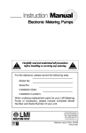
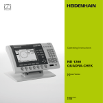
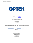
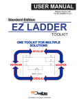
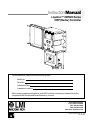
Instruction Manual
Liquitron™ DR5000 Series
ORP (Redox) Controller
For file reference, please record the following data:
Model No:
Serial No:
Installation Date:
Installation Location:
When ordering replacement parts for your LMI Controller or accessory, please include the
complete Model Number and Serial Number of your unit.
8 Post Office Square
Acton, MA 01720 USA
TEL: (978) 263-9800
FAX: (978) 264-9172
http://www.Imipumps.com
1
Replaces same of Rev. D 1/98
1761. E 9/99
Contents
1.0
Introduction ...................................................................................................................................... 3
2.0
Unpacking ........................................................................................................................................ 3
3.0
Installation ........................................................................................................................................ 4
3.1 Mounting the Electronic Enclosure ....................................................................................... 4
3.2 Electrical Installation .............................................................................................................. 6
3.2.1 Terminal Board Signal Description .......................................................................... 7
3.2.2 Field Wiring Instructions (Optional 4-20 mA Output) ................................................ 8
3.3 ORP Adjustment Pump(s) .................................................................................................... 9
3.4 Keypad and Display ............................................................................................................... 9
4.0
Operation ....................................................................................................................................... 11
4.1 Proportional Mode ................................................................................................................ 12
4.2 On/Off Mode ........................................................................................................................ 13
4.3 Alarms ................................................................................................................................. 14
4.4 Calibration (Viewing Last Calibration Data) ......................................................................... 15
4.5 Performing a New Calibration .............................................................................................. 16
4.6 Pump Timers and Solenoid Valve Control Timers .............................................................. 17
4.7 Advanced Menu List ............................................................................................................ 20
5.0
Maintenance .................................................................................................................................. 20
5.1 ORP Electrode and Cable ................................................................................................... 20
6.0
Troubleshooting ............................................................................................................................. 21
6.1 Error Messages .................................................................................................................. 21
7.0
DR5000 Specifications .................................................................................................................. 22
8.0
Parts List ....................................................................................................................................... 24
9.0
Exploded View ............................................................................................................................... 25
10.0
Program Log .................................................................................................................................. 26
11.0
Statement of Limited Warranty ...................................................................................................... 27
2
1.0
Introduction
The Liquitron™ DR5000 Series ORP (Oxidation Reduction Potential) Controllers are designed for a variety of industrial
ORP applications including metal finishing, water treatment, printed circuit board manufacturing and waste treatment.
The DR5000 is a microprocessor-based ORP controller with a backlit customized display and tactile keypad for ease of
programming. The DR5000 allows independent programming of control methods (On/Off or Proportional) for reducing
agent (Pump A) or oxidizing agent (Pump B) dosage. Independent high and low ORP alarms may be set with activation
of the ‘Alarm relays.’ A third relay output is available for activating a solenoid valve or other devices.
The controller is compatible with any ORP electrode that generates a mV signal. Two point or single point ORP calibrations
may be performed. Timer functions for pump ‘Run’ time and solenoid ‘Delay’ times can be programmed to operate a
solenoid pump valve. An ‘Advanced Menu’ allows selection of special features such as a ‘Point 3’ (inflection point) for
the control profiles of the reducing agent or oxidizing agent pumps for finer control. The DR5000 features continuous nonvolatile memory backup, voltage selection, pre-amplifier outputs, flow and level switch inputs as standard, 4-20 mA recorder
output is optional.
2.0
Unpacking
Your carton will contain the items shown in Figure 1. Please notify the carrier immediately if there are any signs of damage
to the Controller or its parts. Contact your LMI Distributor if any of the parts are missing.
There is a number label on the inside cover of the unit; for easy reference, you should note the model and serial numbers
on the front cover of this instruction manual.
Quick Reference Guide
DR5000 ORP Controller
User Manual
Figure 1: Unpacking Items
3
3.0
Installation
Pre-Installation
Cord & Voltage Code
!
CAUTION
Be sure that the unit has a plug and voltage code compatible with the power source that you intend to use.
Environment:
The housing is corrosion and spray resistant but should not be subjected to excessive spray or ambient temperature over
122° F (50° C). Never immerse the unit.
Installation
The DR 5000 Controller should be mounted on a solid, stable surface. ORP adjustment pumps should be installed following
the manufacturer’s recommendations. For installations requiring longer cables, consult your distributor. The electrode
installation will vary, depending on the process used. In general, the temperature electrode and ORP electrode should be
mounted together, and placed far enough downstream from the source of ORP adjusting solution that sufficient mixing
may occur, but close enough to eliminate hydraulic lag time of response. Refer to the typical installation diagrams (Figures
3A and 3B) on the following pages.
3.1
Mounting the Electronic Enclosure
The DR5000 Control module is supplied with integral wall-mounting flanges. It should be hung with the display at eye
level, on a vibration-free structure, in a location where liquids will not be splashed on it. All four (4) top mounting holes
should be used for structural stability. The control module requires the following clearances:
4
Figure 2: Minimum Clearances
Figure 3A: Typical In-Line Installation
Figure 3B: Typical Batch Installation
5
3.2
Electrical Installation
ELECTRICAL CONNECTIONS
!
CAUTION
To reduce the risk of electrical shock, the control or metering pump must be plugged into a grounded outlet with
ratings conforming to the data on the control panel. It must be connected to a good ground. DO NOT USE
ADAPTERS! All wiring must conform to local electrical codes.
Electrical installation of the DR5000 Series ORP controllers consists of plugging the control module into a proper line
outlet. Based on model number, the following voltages and receptacles are required:
DR5000-1A
DR5000-1B
115 V, 60 Hz
USA Cord
DR5000-3A
DR5000-3B
230 V, 50 Hz
DIN Cord
DR5000-6A
DR5000-6B
230 V, 50 Hz
AUS/NZ Cord
DR5000-01A
DR5000-01B
115 V, 60 Hz
No Cord
DR5000-2A
DR5000-2B
230 V, 60 Hz
USA Cord
DR5000-5A
DR5000-5B
230 V, 50 Hz
UK Cord
DR5000-7A
DR5000-7B
230 V, 50 Hz
SWISS Cord
DR5000-02A
DR5000-02B
230 V, 50/60 Hz
No Cord
Connect the ORP adjustment pump(s) to the terminal strip for On/Off mode control (connect to receptacles directly for
115 V models) or to cables for Proportional Output mode control. Connect the ORP electrode to the BNC connector
on the right side of the control module. Take care not to twist or strain the wires. You may optionally connect an alarm,
solenoid, flow switch and low level switch. You may also connect the mA connections (optional). The ±5 V supply for
electrode pre-amplification is also accessed on the terminal strip. There is a 500 W maximum resistance for 4-20 mA option
when used.
6
Figure 4: Electrode and Pump Connections
Terminal Strip Wiring
Figure 5: Terminal Strip
3.2.1 Terminal Board Signal Description
Terminal blocks are TB1-TB4 from left to right, and Pin 1 is at the bottom of each terminal block.
TB1 Terminal Strip
TB1
TB1
TB1
Pin 1-Pin 3 .......... Earth connection (one for input power connection)
Pin 4-Pin 9 .......... Neutral power connection (one for input power connection)
Pin 10 ................. AC Mains live input
TB2 Terminal Strip
TB2
TB2
TB2
TB2
TB2
Pin 1 ................... Form A contact closed when Pump B (oxidizer) is ON
Pin 2 ................... Form A contact closed when Pump A (reducer) is ON
Pin 3-4 ................ Form C contact activated, (if programmed) when ORP is within programmed limits
(solenoid pump)
Pin 5-6 ................ Form C contact activated when Alarm Set Point 2 exceeded (powered output contacts)
Pin 7-8 ................ Form C contact activated when Alarm Set Point 1 exceeded (powered output contacts)
TB3 Terminal Strip
TB3
TB3
TB3
TB3
TB3
TB3
Pin 1-2 ................ Opto isolated input - low or short stops pumps Set Point (OFF on display)(Remote ON/OFF)
Pin 3-4 ................ Opto isolated output - low when alarm condition exists
Pin 5-6 ................ Opto isolated output - pulse train to drive Pump A
Pin 7-8 ................ Opto isolated output - pulse train to drive Pump B
Pin 9-10 .............. Spare, not programmed
Pin 11-12 ............. 4-20 mA output proportional to ORP (programmable limits) (optional)
TB4 Terminal Strip
TB4
TB4
TB4
TB4
TB4
TB4
Pin 1-2 ................ Opto isolated input - flow switch input (add jumper if no flow switch is used)
Pin 3-4 ................ Opto isolated input - level switch input (add jumper if no level switch is used)
Pin 5-6 ................ Serial Communications (NA)
Pin 7-8 ................ Temperature input (NA)
Pin 9-10 .............. Power voltage source for preamp
Pin 11-12 ............. Spare, not programmed
7
3.2.2 Field Wiring Instructions
Typical US field installation would find a 6 ft (2 m) AC cord wired and two (2) 1 ft (30 cm) AC receptacles (On/Off mode)
or two (2) 10 ft (3 m) pump drive cables (Proportional mode) installed. A BNC receptacle would be installed for the ORP
probe.
Connect the two (2) pumps appropriately. Install the probe, run the cable back to the controller and attach to BNC
receptacle. If the probe is farther than 25 ft (7.6 m) from the controller, a preamp may be desirable to reduce noise effects.
If this is the case, use +5V/-5V from control box TB4 Pin 9-10 for your preamplifier. Current draw must not be greater
than 10 mA.
If a flow meter and/or low-level tank switch is available, run wires to the controller entering through one of the spare cable
ports. Remove the appropriate jumper(s) and attach the external wires. Polarity does not matter. Wire size #20-22 is
adequate.
Alarm relays 1 and 2 are provided to signal an out of tolerance condition externally. These are Form C contacts, providing
a common, a normally open, and a normally closed connection. These terminals provide power output.
A solenoid drive relay (Form C contacts, providing a common, a normally open and a normally closed connection) is
provided that can be connected to drain a tank when the ORP is within programmed limits. A delay can be programmed
after initially entering this programmed zone, to allow conditions to settle within the tank. The duration of solenoid On
time is also separately programmable. Wire size #16-18 is recommended. These terminals provide output power (main
voltage).
The optional 4-20 mA PCB provides a fully programmable 4-20 mA output based on the ORP readings. The optional PCB
plugs into the back of the computer PC board, as shown in Figure 6.
8
Figure 6: Circuit Board
3.3
ORP Adjustment Pump(s)
There are two (2) versions of the DR5000, one is the On/Off Output mode, and the second is Proportional Output mode.
In the On/Off Output mode, the DR5000 ORP Controller will operate any ORP adjustment pump(s) which operate on
the same line voltage as the controller itself. Combined continuous controlled load must not exceed
6A @ 115V or 3A @ 230V. To ensure efficient control, the pumps should be capable of delivering at least 150% of the
maximum pumping requirement. Install and calibrate the pumps according to the manufacturer’s recommendations.
In the Proportional Output mode, the DR5000 ORP Controller will operate any LMI Series A9, A7, B9, B7, C9, C7, E7
or L7 pump, or any other pump which operates by providing direct proportional response to a modulated pulse input signal.
The pumps must be set to the ‘external’ control mode. To ensure efficient control, the pumps should be capable of
delivering at least 150% of the maximum pumping requirement. Install and calibrate the pumps according to the
manufacturer’s recommendations.
3.4
Keypad and Display
The DR5000 ORP Controller menu allows the user to input all the variables necessary to customize the controller for the
application. The keypad is used for all programming.
Figure 7: Keypad
9
KEYS:
This key is used to set up the control profile for the reducer dosing pump (holding the key for five (5)
seconds will allow priming of Pump A) (Factory setting 90 SPM).
This key is used to set up the control profile for the oxidizer dosing pump (holding the key for five (5)
seconds will allow priming of Pump B) (Factory setting 65 SPM).
This key is used to program the high and low alarm points and hysteresis (On/Off mode). It also allows
programming of the optional mA output when installed.
This key is used to program ‘run times’ for Pumps A and B, ‘delay times’ 1 and 2 for actuating and
controlling a solenoid valve (when programmed On in the advanced features menu). This key also allows
setting of the controller response rate D. If pump run time is over 11:01 hours, the run time is disabled, the
pump will not be stopped and will run continuously.
This key when pressed will display details of the last successful electrode calibration (holding the key
for five (5) seconds will allow entry into a new calibration procedure [single or two point]).
Pressing this key will cause the display to alternate showing various settings (holding the key for
five (5) seconds will allow entry to the ‘advanced features’ menu).
This key is used for starting and stopping (run or edit) the pumps and changing set points in the controller.
It changes the mode of the controller from Run to Off.
10
or
These keys are used to change values on the display.
+
Simultaneously pressing these two keys will lock the keypad to prevent casual tampering.
Pressing them a second time will unlock the keypad. Wait five (5) seconds between locking
and unlocking.
4.0
OPERATION
In the default mode, as shipped from the factory without any extended features programmed in the ‘menu’, the controller
is set to operate two dosing pumps towards a single desired ORP region as defined by the set points. It will do this in one
of two ways, On/Off or Proportional, shown graphically below:
ORP
On/Off Control
ORP
Proportional
When the unit is plugged in, the computer powers up and the display illuminates. The display flashes the ORP reading and
Off. This indicates the pumps will not operate and the unit is in the Off mode. When the
key is pressed the controller
starts and switches into the Run mode.
EXAMPLE:
(Proportional Controller)
This display shows a ORP value of 900. Pump A is
flashing indicating that the reducer pump is in
operation. The pump will stop pumping after 46:35
minutes and alarm will activate if set point is not
reached.
For two (2) seconds in every eight (8) seconds the
display shows pump speed in pulses/minute. The
pulses/min displayed relates to the pump that is in
operation.
When the ORP value exceeds the programmed
ORP alarm point, the ALARM flashes and the
alarm relay is activated.
Throughout this manual, the term ‘pulse’ is used to describe the mechanical stroke of the pump, as ‘strokes per minute’
(SPM).
11
4.1
Proportional Mode
The unit is shipped pre set at the factory for the Proportional or On/Off mode. To change the unit to the opposite mode
see ‘Advanced List,’ Option 2, on page 20.
Pump A Control Profile
Controller must be in Off mode
to program changes.
ORP
Pressing
switches the mode back and forth from Run to Off. The ORP set points and pump speed (pulses/min)
can be changed only in the Off mode.
(1) ...... Press
to display current settings.
or
to the increase/decrease the ORP value of
(2) ...... Press
Set Point 1 for turning on ‘Pump A.’
(3) ...... Press
again to advance to next Pump A setting.
(4) ...... Press
or
to increase/decrease the pump speed
(pulse/min) for Pump A at ORP Set Point 1.
(5) ...... Press
again. This changes to data for Set Point 2 for
Pump A.
or
(6) ...... Press
Set Point 2.
(7) ...... Press
to increase/decrease the ORP for
again to advance to next setting.
or
to increase/decrease pump speed
(8) ...... Press
(pulse/min) for Set Point 2.
12
(9) ...... Pump B (Oxidizer Pump) is programmed in a similar way.
If ‘Point 3’ is selected in the Advanced Features menu, the user will be prompted to enter a ORP value for Set Point
3 and a Pump Speed at Set Point 3.
4.2
On / Off Mode
(50 mV)
Pump A Control Profile
For On/Off Controllers with relay outputs
(instead of pulse outputs) each pump is programmed
as follows:
Controller must be in Off mode to program changes
(1) ...... Press
(2) ...... Press
(3) ...... Press
to view Pump A settings.
or
to increase/decrease ORP Set Point.
again to advance to next Pump A settings.
or
to program D (Hysteresis) ORP period for
(4) ...... Press
relay. In this example, Pump A will turn on at a ORP of
150.0 mV (set point + D mV). Pump A will turn off when
ORP reaches 100 mV.
(5) ...... Pump B (Oxidizer Pump) is programmed in a similar way.
In the example below, Pump B will turn on at a ORP of -150 mV (Set Point - D ORP) and will turn off when ORP reaches
100 mV.
13
It is highly recommended that the hysteresis (pump off function) be used to prevent relay chatter.
The function of the hysteresis is to prevent pump relay chattering. It operates by allowing the pump to be turned on when
the control point plus (or minus) the hysteresis value has been met, but does not allow the pump to turn off until the control
point has been met. The chosen value will be used for both upper and lower set points.
The hysteresis, or dead band, designates how many ORP units beyond set point the pump runs before turning off. Any value
from 0 to 100 mV is acceptable. If use of this function is undesirable, set it to 0.
4.3
Alarms
to view Alarm settings.
(1) ...... Press
(2) ...... Press
or
to program Alarm Point 1 (low alarm).
(pump B)
again to save settings and to advance to next
(3) ...... Press
Alarm set point.
(4) ...... Press
or
(5) ...... Press
to program Alarm Point 2 (high alarm).
(pump A)
again to save data and to advance to hyster-
esis setting.
(6) ...... Press
or
to program Alarm Hysteresis value. This
is the point where the alarm turns off.
If the 4-20 mA option board is installed, the following screens will
appear. If these do not appear and the 4-20 mA PCB is installed,
go to Section 4.6, Advanced Menu, and program option “7” to “1”
and option “6” to “1”.
(7) ...... Press
14
again to display current mA value.
(8) ...... Press
again to program the 4-20 mA output for
Point 1.
(9) ...... Press
or
to select the mV value for Point 1 mA
output. Default is:
4 mA
= - 1000mV
20 mA
= +1000 mV
(10) .... Press
again. Press
or
to select the mA value
at Point 1.
(11) .... Press
2 PT CALIBRATION
again. Press
or
to select the mV value
for Point 2 mA output.
(12) .... Press
again. Press
or
to select the mA value
at Point 2.
4.4
Calibration (Viewing Last Calibration Data)
(1) ...... Press the
key once.
CALIBRATE will be visible and the ‘mV/ORP’ and ‘%’ (slope)
of the last successful calibration will be displayed.
‘1 Point’ indicates that the previous calibration was a one point
calibration.
15
4.5
Performing a New Calibration
For two point calibration, the default settings are Buffer 1 = 80.0 mV and Buffer 2 = 400 mV; but these values may be
changed.
The calibration parameters (buffer mV and one or two point calibration) of the previous calibration are the initial values
for the current calibration.
The unit must be placed in the Off mode. The unit cannot be calibrated in the Run mode.
Calibration (e.g., 2 Point)
(1) ......
+ 5 seconds.
Hold the ‘Calibrate’ key down for five (5) seconds.
Calibrate will start flashing.
(2) ...... Press
again.
‘2 Point’ will start flashing. Use the
or
toggle between ‘1 Point’ and ‘2 Point.’
(3) ...... Press
again.
The ‘Buffer 1’ value will start flashing. Use
keys to program Buffer 1 mV value.
(4) ...... Press
keys to
or
again.
The
symbol will prompt you to put the probe in
Buffer 1. Wait for the mV value to settle.
(5) ...... Press
again.
This will accept the first calibration value and will display the
Buffer 2 mV. Use
or
keys to program Buffer 2 (or leave) as
desired.
16
(6) ...... Press
again and the symbol will prompt you to put
the probe in Buffer 2. Wait for the mV value to settle.
(7) ...... Press
again. This will accept the second calibration
value and will display the mV/mV and % Slope result of the
calibration.
again to accept this calibration and exit
(8) ...... Press
calibration mode.
Press any other key to abort calibration.
For a single point calibration, only one buffer is used. The theoretical value for 0.0 mV is used to complete the
Calibration Curve.
If the calibration is unsuccessful (slope < 70% or offset > ± 100
mV) and Error Calibrate and E7 are displayed; the calibration
should be repeated or else the controller reverts to using the ‘last
successful’ calibration performed.
A slope of less than 70% indicates a dirty/faulty probe or
contaminated buffer.
4.6
Pump Timers and Solenoid Pump Valve Control Timers
It is not possible to change timer values while in Run mode. Unit must be in the Off mode to change values and
settings.
Pump Run Time:
This timer is set to the maximum time the pump can be on. If the timer is set to over 11:01 hours, the timer is disabled.
This timer is started when a pump is On and the ORP value is outside the set points. The controller will stop the pumps
when the time reaches ‘0’ and activate Alarms. The run time is reset each time the ORP enters the desired set point region.
Solenoid Delay Pump Valve Time:
The Solenoid Valve Relay output may be activated when the ORP is within the set points for the time specified by ‘Delay
1.’ This may be used for system integration and for emptying a batch tank, etc.
The ‘Delay 1’ Timer defines the period to allow ORP and system parameters to settle.
The ‘Delay 2’ Timer (On time) defines how long the valve will stay open. When these Delay Timers are active, pump
dosing cannot take place but the DR5000 will monitor the ORP. The ‘Delay 2’ timer starts when the outputs are activated.
If the ORP drifts outside of the set point and range, the solenoid relay will be deactivated.
If a ‘Delay 2’ time goes below one hour, then the display will change to ‘minutes : seconds’ from ‘hours : minutes.’
17
Setting Timers
The unit must be in the Off (edit) mode to change the timer settings.
(1) ...... Press the
(2) ...... Use
key to view the run time for Pump A.
or
to adjust to desired maximum run time.
The ‘hr : min’ will change to ‘min : sec’ automatically as the run time is reduced below 1 hour.
(3) ...... Press the
(4) ...... Use
or
key to advance to run time for Pump B.
to adjust to desired maximum run time.
The ‘hr : min’ will change to ‘min : sec’ automatically as the run time is reduced below 1 hour.
Delay Timers are factory set in the deactivated mode. The ‘Delay 1 and Delay 2’ Timers are activated/deactivated
in the ‘Advanced Features Menu.’ These screens will not display when the delay option is deactivated.
Solenoid Valve Control
(5) ...... Press the
key to advance to ‘Delay 1’ time
(if activated). ‘Delay 1’ is the wait time after ORP enters the
desired region, before the Solenoid is activated.
key to advance to ‘Delay 2’ time
(6) ...... Press the
(if activated). ‘Delay 2’ is the Solenoid On time.
If the ORP should go out of the desired range during ‘Delay1’ or ‘Delay 2’, the Solenoid cycle will terminate. It will
start again from zero when ORP re-enters the desired region. If ORP remains in the desired region, the controller
will enter Off mode at the end of the Solenoid On time. The controller turns On again in one minute and the cycle
repeats.
18
(7) ...... Press
key to advance to Response Rate. This is
programmed in D ORP units.
The smoothing of the input signal is determined by D ORP time.
The following values can be programmed (min : sec):
00 : 01, 00 : 10, 00 : 20,.......04 : 00 (In increments of 10 seconds)
When 00 : 01 is programmed the controller responds to a change in input in one (1) second.
If 00 : 10 is selected the controller responds to a change in input in ten seconds. (i.e., the value displayed is the average
of the 10 previous 1 second readings.)
Examples: The sampling time (delta) is 00 : 10 and the current reading is 20.00 mV. When the ORP input is increased
instantaneously to 120.00 mV, the display will respond as follows:
Seconds 0
ORP (mV) 20
1
30
2
40
3
50
4
60
5
70
6
80
7
90
8
9
10 11
100 110 120 120
If the sampling was 00 : 01 seconds, the response would be:
Seconds 0
ORP (mV) 2
1
2
3
4
5
6
7
8
9
10 11
120 120 120 120 120 120 120 120 120 120 120
Display Key:
While in the Run mode the
key can be pressed once to display current parameters. Each screen will come up for
three (3) seconds and then returns to ORP or System Run display automatically (screens shown are: i.e., mV, mA).
+ 3 Seconds
Similarly, the Pump Control Points are consecutively displayed in the Run mode by pressing the ‘Pump A’ or ‘Pump B’
keys once.
+ 1 Second
19
4.7
Advanced Menu List
Holding the
key for five (5) seconds allows programming of Advanced Features in a Menu. The menu can be
accessed by pressing the Display/Menu key for five (5) seconds while the controller is in the Edit or Off mode.
The first item displayed is the software revision. Pressing Display/Menu again cycles to the first option. The first number
or
to change the setting.
is the option. The second is the setting. Use the
Option Setting
1
1
0
Control returns to Run 60 seconds after last keypress
Run/Edit key is On/Off
2
1
0
2
On/Off Control
Proportional Control (and On/Off)
Proportional Control
3
1
0
Point 3 Programming Enabled
Point 3 Programming Disabled (Two point only)
4
1
0
Solenoid programmed to switch on after programmed time Delay 1 and to switch Off
after programmed time Delay 2
Solenoid Disabled
5
1
0
Communications Enabled - Option Board must be fitted
Communications Disabled
6
1
0
mA Enabled - Option Board must be fitted
mA Disabled
7
1
0
Allows editing of #5 & #6
Lockout #5 and #6
The Option Board (34310) is required for Options 5 and 6.
5.0
Maintenance
5.1
ORP Electrode and Cable
The most frequently replaced part is the ORP electrode, which will deteriorate with age. Refillable electrodes should be
checked for level frequently, and replenished with filling solution as necessary. An electrode may also fail because of:
• aging (slow response to changing ORP)
• coatings over the glass bulb (slow response to changing ORP)
• abrasion of the glass bulb (shift in calibration)
• chemical attack
• breakage
If you experience instability or lack of response, check the electrode, replace if necessary and recalibrate. Follow
manufacturer’s recommendation for cleaning the electrode. Take care not to damage input cables, or allow the connections
to get wet.
20
6.0
Troubleshooting
6.1
Error Messages
Troubleshooting and repair of the malfunctioning unit should only be attempted by qualified personnel using caution to ensure
safety and limit unnecessary damage.
Should an error or alarm condition occur, the controller will alert the operator to this by flashing an Error Message. These
messages are depicted below with a brief explanation.
Turn system off to clear error message.
E1 =
LOW LEVEL SWITCH
E2 =
FLOW SWITCH
E3 =
ALARM 1: LOW ORP (PUMP B)
E4 =
ALARM 2: HIGH ORP (PUMP A)
E5 =
Pump B ‘LOCKOUT TIMER’
E6 =
Pump A ‘LOCKOUT TIMER’
E7 =
CALIBRATION ERROR
E9 =
FAULTY/DISCONNECTED PROBE
21
7.0
DR5000 Specifications
Power Requirements ____
115 VAC ±15%, 60 Hz
230 VAC ±15%, 50 Hz
Voltage input selectable via a selector switch located on the
I/O PCB.
Inputs ________________
Flow Switch, Remote On/Off, Spares. All low voltage inputs active low,
i.e., the active state is when the switch is closed.
The switch must be capable of switching 2 mA at ±15VDC.
Outputs _______________
Pulse Pump A and B, Alarm.
All low voltage outputs capable of switching 2 mA at +24 VDC. The
pulse output frequency range will be 0-100 per minute. The pulse output
active low. The pulse width 100 ms in the active low) state.
Opto-Isolated NPN transistor open
collector configuration.
Output Type_______
Keypad _______________
Material:
Actuation Force:
Travel:
Termination Connector:
ORP Probe Input _______
Accuracy:
Resolution:
Input ORP Range:
Input Impedance
Differential:
Input Impedance
Common:
ESD Protection:
Relays ________________
Alarm Relays (2):
Solenoid Valve Relay (1):
Current/Voltage Rating:
Contact Type:
Pump On/Off Relay (2):
(On/Off CONTROL):
Fuse:
22
Nine key membrane keypad with tactile response.
(The switches are multiplexed 3 x 3.)
Polyester with a hard coat finish
2.6 N to 3.3 N
0.65 mm
6-way gold plated Berg clincher type
65801-035
±0.1 mV (500M W probe ambient cycle 0° F to 113° F (0° C to 45° C)
0.1 mV
-2000 to 2000 mV
1013 W
1016 W
700 V
Fuse protected
Electromechanical
115/230 VAC, 10A/6A
10A, 115 VAC or 6A, 230 VAC
Normally open and normally closed contacts (FORM C) Change over
relay 1
15V/230VAC, 10A/6A (NO)
On/Off Relays are Fuse Protected
(FORM C). Normally open relay
4A, 250 VAC time delay (Anti-surge)
LCD Display
Operating Voltage:
Operating Temperature
Viewing Area:
Backlight:
5V
32° F to +122° F (0° C to + 50° C)
1.2 x 1.8 inches (30.5 mm x 45.7 mm)
An 8 emitter (dual LED type), double row, reflective backed, backlight
module will be used. The light output color and reflective backing
color will be high performance green.
Memory Backup ___________
Data Retention No Power:
Light Output Area:
EEPROM
10 years minimum
1.2 x 1.8 inches (30.5 mm x 45.7 mm)
Pre-amplifier
Output Voltages __________
Voltage:
Output Voltage Tolerance:
Current Output:
±5 V
±5% maximum
±10 mA maximum
Computer
(NA)
Communications __________
4-20 mA Load:
Accuracy:
Control Outputs
(Pump A / Pump B)
(Proportional Control)
Fault:
Control Inputs
Remote On / Off:
Flow Switch:
Low Level Input:
Aux (spare):
500 Ohms maximum resistance
±0.2 mA . The 4-20 mA shares a common ground with +15 V and the
low voltage inputs.
Opto-Isolated Open Collector (2 mA)
Opto-Isolated Open Collector (2 mA)
Opto-Isolated (2 mA)
Opto-Isolated (2 mA)
Opto-Isolated (2 mA)
Opto-Isolated (2 mA)
Environmental ___________
Operating Temperature:
Enclosure:
Printed Circuit Boards conformally coated
32° F to 122° F (0° C to 50° C)
IEC IP65, NEMA 4X - Hardwired
IEC IP, NEMA 12X
Mechanical ______________
Two printed circuit boards
(3 if option installed)
(Microcontroller & Display) - Low Voltage
Transformer, fuses, terminal blocks, relays
(4-20 mA output) - Low Voltage
Control Board:
Terminal/Power board:
Option Board:
23
8.0
Parts List
Key No. Part No.
1
2
3
4
5
6
7
8
9
10
11
12
13
14
15
16
17
18
19
20
21
22
23
24
25
26
27
28
24
34691
32186
32187
32209
34270
34716
31632
34329
34330
25957-1
36810
31571
34074
34088
30588
37526
31617
32094
32211
32352
32395
34911
35711
33636
34930
34315
30749
30751
30752
34783
30754
34784
34310
35712
Description
Housing, Machined
Screw, 4-40 x .37
Nut, 4-40 Flush
Latch, Machined
I/O Board Assembly
Standoff, Self Adhesive
Screw, #6 x .38
BNC Cable Assembly
Ribbon Cable Assembly
Cord Clamp (PG-9 clamp for female outlet power cord)
Dowel
Clamp, Cord (PG-9 clamp for 4-pin cable)
Gasket, Foam
Cover, Utility Box
Label, LMI Logo
Front Panel Assembly
Cover, Liquitron™
Label, Housing cover LMI
Cap, .125 x .38
O-Ring, Sponge
Screw, Self-Tapping
Cover, Fuse
Cord, Power, 115V, NEMA 15-R - DR5000-XA (On/Off)
4-Pin Cable - DR5000-XB (Proportional)
Terminal Cover Label
Circuit Board Support
Power Cord 115 V - DR5000-1A/B
Power Cord 220 V US - DR5000-2A/B
Power Cord DIN - DR5000-3A/B
Cord Assembly UK - DR5000-5A/B
Power Cord AUST - DR5000-6A/B
Cord Assembly SWISS - DR5000-7A/B
4-20 mA Circuit Board Assembly
Fuse, 4 Amp
9.0
Exploded View
25
10.0 Program Log
For record keeping, a program log is provided below.
Proportional On/Off Proportional On/Off
Pt 1 Pt 2
Pt 1 Pt 2
Pump A Set Point
100
Pump A Pulses/Min 20
Pump B Set Point
-100
Pump B Pulses/Min 30
750
90
-750
65
100
///
-100
///
Hysteresis 1
Hysteresis 2
///
///
50
50
Alarm 1
Alarm 2
Hysteresis
Alarms
-1000 mV
1000 mV
10 mV
///
///
///
///
///
Alarms
mV
mV
mV
mA Response
4.0 mA
-1000 mV
20.0 mA
1000 mA
mA Response
mA
mV
mA
mV
Timers
20:00 Min
30:00 Min
00:10 Min
Timers
Pump A On-Time
Pump B On-Time
Sampling Time
Delay to Solenoid ON
Solenoid On-Time
5:00 Min
20:00 Min
Current Low
Signal Low
Current High
Signal High
Number of Points
Buffer 1
Buffer 2
26
///
///
///
Calibration
2
80.0
400.0
Calibration
11.0 Statement of Limited Warranty
LMI TERMS AND CONDITIONS OF SALE:
1. Seller warrants that the equipment delivered by it to the Buyer is in accordance with the Seller’s published specifications and is of
the kind and of the description contained in seller’s invoice.
THIS WARRANTY IS IN LIEU OF AND TO THE EXCEPTION OF ALL OTHER WARRANTIES, EXPRESS OR IMPLIED,
INCLUDING BUT NOT BY WAY OF LIMITATION, WARRANTIES OF MERCHANTABILITY OR FITNESS FOR A
PARTICULAR PURPOSE. DISTRIBUTOR IS NOT AUTHORIZED TO BIND THE COMPANY FOR ANY OTHER WARRANTY.
THE FOREGOING STATES THE COMPANY’S ENTIRE AND EXCLUSIVE LIABILITY, AND DISTRIBUTOR AGREES TO
HOLD THE COMPANY HARMLESS FROM AN IMPROPER APPLICATION OF PRODUCTS.
2. Seller’s liability for breach of the foregoing warranty is expressly limited to the repair or, at Seller’s option, replacement of such
equipment FOB factory, or Acton, MA. Such obligation to repair or replace such equipment shall terminate 12 months after the delivery
to such equipment to the Buyer. In no event shall the Seller be liable for any consequential damages resulting from any breach of
warranty.
The Company warrants the Products in accordance with the statement of warranty policy included herein except that pump Product
series designated as “A,” “B,” “C,” “E” and “P” and Liquitron™ series of product shall be warranted for a period of two (2) years from
the date of delivery from Company; and except replacement elastomeric expendable parts and probes which are not covered by any
warranty either express or implied.
If the Buyer claims that the warranty contained herein has been breached, it shall immediately notify the Seller of such claimed breach
in writing at Seller’s address contained herein. The Buyer shall render necessary assistance to Seller, and it shall furnish adequate means
for operating and testing such equipment.
The SOLE PURPOSE of the foregoing stipulated exclusive remedy shall be to provide to the Buyer free repair or at Seller’s option
replacement of non-conforming equipment in the manner provided herein. This EXCLUSIVE REMEDY shall not be deemed to have
failed of its essential purpose so long as the Seller is willing and able to repair or at its option replace non-conforming equipment in
the prescribed manner.
3. Seller shall not be liable for any loss or damage for delays in delivery or compliance with any warranty provision contained herein
due to acts of God, acts of civil or military authorities, fires, floods, wars, riots, labor strikes or actions, accidents or delays in
transportation or any other cause beyond the Seller’s control.
4. All Shipments by Company to Distributor shall be made F.O.B. Factory, Acton, Massachusetts 01720, U.S.A. unless special
arrangements are agreed to by both Company and Distributor.
5. The within terms and conditions constitute the entire agreement of the Buyer and Seller. Such terms and conditions may not be
modified, altered or amended except by a writing signed by both parties. Such terms and conditions shall be binding upon the parties
hereto, their successors and assigns. In the event that any term or condition shall be held to be invalid or unenforceable, all other terms
shall remain in full force and effect. Such terms and conditions shall be governed and construed in accordance with the laws of the
Commonwealth of Massachusetts.
27
8 Post Office Square
Acton, MA 01720 USA
TEL: (978) 263-9800
FAX: (978) 264-9172
http://www.Imipumps.com
28
© 1999 LMI Milton Roy - All Rights Reserved
Printed in USA
Specifications subject to change without notice.
Liquitron is a trademark of Liquid Metronics, Inc.