1
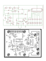
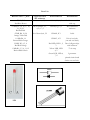
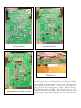
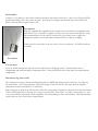
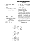
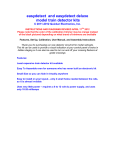
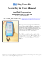
Blue Ring Tester Kit
Assembly & User Manual
AnaTek Corporation
100 Merrimack Road, P. O. Box 1200
Amherst, NH 03031 USA
603.321.0884, FAX 603.836.4436, [email protected]
This ring tester is an inexpensive and effective
way to test any high Q inductive component. It
is especially useful for doing a quick check on
flyback, line output transformers and other high
frequency wound components like deflection
yoke windings and SMPS transformers.
The LEDs on the left side show the Q of the
device being tested, more lights = higher Q, i. e.,
no lights = short circuit, red = Bad or low Q,
yellow = ??? or medium Q, green = Good or
high Q.
This document was written by Bob Parker and edited by John Bachman at AnaTek Corporation. Some graphics
and text courtesy of Silicon Chip March/April issue 2004.
Parts List
Resistors all 5% ¼ Watt
270 Ω, R15
Red-Blue-Brown
2.2 KΩ, R7, 10, 16, 17, 18,
21, 22, 23
Red-Red-Red
4.7KΩ, R8, 19, 20
Orange-Violet-Red
10 KΩ, R4, 14
Brown-Black-Orange
22 KΩ, R3, 4, 5, 6
Red-Red-Orange
1 MΩ, R1, 2, 5, 6, 11, 12
Brown-Black-Green
Capacitors all 16
WV minimum
1 nf ceramic, C3, 8
Semiconductors
Miscellaneous
1N4148, D1, 2, 3
Pushbutton switch
with cap
100 nf ceramic, C1,
4, 5, 6 7, 9
2N3904, Q1, 2, 3
Blue Hammond
enclosure
10 uf electrolytic, C2
CD4069, IC1
Label
CD4015, 1C2
Pair of test leads
(one red one black)
Red LED, LED 1, 2,
3
Pair of alligator clips
with insulators
Yellow LED, LED
4, 5
3” tie wrap
Green LED, LED 6,
7, 8
2 grommets
printed circuit board
ferrite core and wire
LED
Construction
As you can see in the photos, all the components are mounted on a single PC board which is then attached to the
enclosure bottom.
Even though the pc board is high-quality with solder-mask it is still wise to check it for defects. To do this,
illuminate the component side with a bright light and examine the copper side very carefully – preferably with a
magnifier – for any hairline fractures in the tracks.
During assembly frequently check for any solder “whiskers” or bridges and pay particular attention to any tracks,
which pass between IC pads, where such defects tend to congregate and hide. It is good practice to install 5 or 6
components and then check the soldering of them under a magnifier. Then move on and install 5 or 6 more.
The PC board is tightly packed and the solder pads are quite small so be very careful with your soldering. Always
lift the iron vertically from a just soldered joint and never wipe it sideways as so many constructors seem to do!
Component Installation Sequence
The kit package contains five plastic bags of components. Install them in the following order:
5% resistors
Capacitors
Semiconductors (See detailed description of LED installation)
Miscellaneous parts
The bag labeled “test” contains an inductor that will use after your unit is assembled. The inductor is not installed
on the pc board.
Installing components
The construction sequence basically installs the smallest components first. The table of color codes above will help
you select the resistor values prior to checking.
It is a good idea to check the value of all of the resistors with an ohm meter as manufacturers occasionally make
labeling mistakes.
Take care with the orientation of the polarized components: the electrolytic capacitor, diodes, LEDs and transistors.
OPTION: Some kit builders are nervous about soldering directly to the integrated circuit pins and prefer to install
sockets for that reason. Feel free to do so although sockets are not included in the kit. If you solder your
integrated circuits and manage to damage them in doing so contact AnaTek. We will replace the integrated circuits
for FREE!
Resistors installed
Capacitors installed
LED shim use
See picture above for use of the plastic shim for aligning the LEDs.
Semiconductors (not LEDs) installed
Put red LED1 in place and green (it looks clear) LED8 into place
and slide the shim under them. Then put the other LEDs into
place and press all of them against the shim. Bend the leads to
hold them into place and solder. Then slide the shim out. This
makes the LEDs the same height. Adjust to line them up in a line.
Short leads go to the outside of the pcb. See the note on the noncomponent side of the board indicating the short lead position.
Test lead installation
Strip approximately 1/8” (2 mm) from one end of the test leads and tin using
rosin core solder. Install the grommets into the enclosure end panel as shown
in the picture. Then push the test leads through the grommets. The outside of
the panel is the finished side. Yes, the leads fit tightly in the grommets, they
are supposed to.
Then solder the test leads to the pc
board and secure them with the tie
wrap. Leave enough slack for the
leads to clear around the pc board
holes for the enclosure bosses.
Strip approximately ¼” (4 mm)
from the other end of the test
leads, do not tin them. Push
alligator clip insulators onto the
leads first and then push the lead
end into the center hole of the
alligator clips as shown in the
picture.
Then solder the lead to the clip,
trimming it so that the insulator
can be slid over the clip. Use
rosin core solder to make the
soldering easier.
Finished pcb assembly
Battery connector
When all the components are on the board, solder the battery snap connector to the
battery pads on the PC board - red to “+” and black to “-”.
Final Assembly
The pc board sits snugly in the bottom enclosure. Fasten the board into place using
the five self-tapping screws.
Remove the battery compartment door from the bottom of the enclosure and feed
the battery leads through the opening and as shown in the picture.
Initial checks
Connect a 9 volt battery to the battery connector and press the button switch once. One or two of the red LEDs
should be flickering, that is the power on signal. If the leads are wrapped around each other more LED’s will
flicker. Press the button again to turn it off.
Test inductor
Wrap the enameled wire supplied into the center holes of the ferrite core supplied in the
bag labeled “Test” over and over tightly to form a test coil as shown in the picture. Strip
the enamel insulation off the ends of the wires for good contact to the copper wire.
Heating the enamel over an open flame will make it easier to strip by scraping.
Connect the ring tester clips to the two wires of your test inductor. All LEDs should be
on solidly.
Test inductor
You are done!
That’s it! Install the enclosure top and secure it with the four self tapping screws. Push the battery into its
compartment and install the battery compartment door. Then put the label on the front and start testing inductive
components!
How does a ring tester work?
The components in many circuits including display drivers, SMPS and tuning circuits contain low loss (high Q)
resonant circuits. The testing technique used in this design is based on the fact that many faults in magnetic
components result in increased loss = reduced Q.
Ring testing gets its name from the fact that a when fast voltage pulse is applied to a high Q circuit the tuned nature
of the circuit will produce a decaying AC voltage of several cycles. More cycles, or “rings”, means higher Q. Few
or no cycles indicates a problem in that component, a shorted winding or some other malady. This tester provides
a quick and easy way to track down such problems.
Consider this set of waveforms from a flyback transformer, aka, LOPT.
Ringing waveforms for a FBT/LOPT
Top (A) is “good”
Bottom (B) is a “shorted winding”
Waveform A shows the ring response to this tester’s pulse for a good FBT/LOPT. Note several rings in a decaying
fashion. This tester will count the rings that exceed its threshold and display them as lit LEDs as shown in the
simulation to the right of waveform A.
Waveform B is the response from the same FBT/LOPT with a shorted diode. The tester will show only one or
two red LEDs lit (solidly as opposed to the blinking power on indication) as show in the simulation to the right of
waveform B.
A short anywhere in the circuit, such as the HOT, will show no rings at all.
Different FBTs will exhibit a different ring response. Some will light all of the LEDs as shown above and others,
will perfectly good, will light only five or six LEDs. It is wise to check a known good component for comparison
before deciding good/bad.
High voltage failures that occur only with power on may not be detected by this low voltage ring tester. Because
this unit uses pulses of 600 millivolts or less it will not detect those failures. However the low voltage permits many
in-circuit tests so making a happy compromise.
While much of our discussion is directed at FBT/LOPT devices the ring tester is not limited to them. It will give a
rough but useful indication of good/no good for many types of Hi-Q (low loss) inductive components.