1
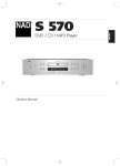
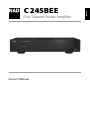
NEDERLANDS
Owner’s Manual
SVENSKA
DEUTSCH
ITALIANO
ESPAÑOL
FRANÇAIS
Four Channel Power Amplifier
ENGLISH
C 245BEE
РУССКИЙ
®
IMPORTANT SAFETY INSTRUCTIONS
ENGLISH
Save these instructions for later use.
Follow all warnings and instructions marked on the
audio equipment.
FRANÇAIS
ESPAÑOL
ITALIANO
DEUTSCH
NEDERLANDS
SVENSKA
1Read instructions - All the safety and operating instructions should
be read before the product is operated.
2Retain instructions - The safety and operating instructions should be
retained for future reference.
3Heed Warnings - All warnings on the product and in the operating
instructions should be adhered to.
4Follow Instructions - All operating and use instructions should be
followed.
5Cleaning - Unplug this product from the wall outlet before cleaning.
Do not use liquid cleaners or aerosol cleaners. Use a damp cloth for
cleaning.
6Attachments - Do not use attachments not recommended by the
product manufacturer as they may cause hazards.
7Water and Moisture - Do not use this product near water-for
example, near a bath tub, wash bowl, kitchen sink, or laundry tub; in a
wet basement; or near a swimming pool; and the like.
8Accessories - Do not place this product on an unstable cart, stand,
tripod, bracket, or table. The product may fall, causing serious injury to
a child or adult, and serious damage to the product. Use only with a
cart, stand, tripod, bracket, or table recommended by the manufacturer,
or sold with the product. Any mounting of the product should follow
the manufacturer’s instructions, and should use a mounting accessory
recommended by the manufacturer.
9
A product and cart combination should be moved with
care. Quick stops, excessive force, and uneven surfaces may
cause the product and cart combination to overturn.
10Ventilation - Slots and openings in the cabinet are provided for
ventilation and to ensure reliable operation of the product and to
protect it from overheating, and these openings must not be blocked
or covered. The openings should never be blocked by placing the
product on a bed, sofa, rug, or other similar surface. This product should
not be placed in a built-in installation such as a bookcase or rack unless
proper ventilation is provided or the manufacturer’s instructions have
been adhered to.
11Power Sources - This product should be operated only from the type
of power source indicated on the marking label. If you are not sure of
the type of power supply to your home, consult your product dealer or
local power company.
The primary method of isolating the amplifier from the mains supply
is to disconnect the mains plug. Ensure that the mains plug remains
accessible at all times. Unplug the AC power cord from the AC outlet if
the unit will not be used for several months or more.
12Grounding or Polarization - This product may be equipped with a
polarized alternating-current line plug (a plug having one blade wider
than the other). This plug will fit into the power outlet only one way.
This is a safety feature. If you are unable to insert the plug fully into the
outlet, try reversing the plug. If the plug should still fail to fit, contact
your electrician to replace your obsolete outlet. Do not defeat the
safety purpose of the polarized plug.
13Power - Cord Protection - Power-supply cords should be routed so
that they are not likely to be walked on or pinched by items placed
upon or against them, paying particular attention to cords at plugs,
convenience receptacles, and the point where they exit from the
product.
РУССКИЙ
14Outdoor Antenna Grounding - If an outside antenna or cable system
is connected to the product, be sure the antenna or cable system is
grounded so as to provide some protection against voltage surges
and built-up static charges. Article 810 of the National Electrical Code,
ANSI/NFPA 70, provides information with regard to proper grounding
of the mast and supporting structure, grounding of the lead-in wire
to an antenna discharge unit, size of grounding conductors, location
of antenna discharge unit, connection to grounding electrodes, and
requirements for the grounding electrode.
NOTE TO CATV SYSTEM INSTALLER
This reminder is provided to call the CATV system installer’s attention to Section
820-40 of the NEC which provides guidelines for proper grounding and, in
particular, specifies that the cable ground shall be connected to the grounding
system of the building, as close to the point of cable entry as practical.
15Lightning - For added protection for this product during a lightning
storm, or when it is left unattended and unused for long periods of
time, unplug it from the wall outlet and disconnect the antenna or
cable system. This will prevent damage to the product due to lightning
and power-line surges.
16Power Lines - An outside antenna system should not be located in the
vicinity of overhead power lines or other electric light or power circuits,
or where it can fall into such power lines or circuits. When installing an
outside antenna system, extreme care should be taken to keep from
touching such power lines or circuits as contact with them might be
fatal.
17Overloading - Do not overload wall outlets, extension cords, or
integral convenience receptacles as this can result in a risk of fire or
electric shock.
18Object and Liquid Entry - Never push objects of any kind into this
product through openings as they may touch dangerous voltage
points or short-out parts that could result in a fire or electric shock.
Never spill liquid of any kind on the product.
WARNING: The apparatus should noT be exposed to
dripping or splashing, and objects filled with liquids,
such as vases, should not be placed on the apparatus.
As with any electronic products, use care not to spill
liquids into any part of the system. Liquids can cause a
failure and/or a fire hazard.
FRANÇAIS
ESPAÑOL
CAUTION
Changes or modifications to this equipment not expressly approved by
NAD Electronics for compliance could void the user’s authority to operate
this equipment.
CAUTION REGARDING PLACEMENT
To maintain proper ventilation, be sure to leave a space around the unit
(from the largest outer dimensions including projections) that is equal to or
greater than shown below.
Left and Right Panels: 10 cm
Rear Panel: 10 cm
Top Panel: 50 cm
DEUTSCH
ITALIANO
The equipment draws its nominal non-operational power from the AC
outlet with its POWER switch in the ON position.
The socket-outlet shall be installed near the apparatus and shall be easily
accessible.
NEDERLANDS
CAUTION
TO PREVENT ELECTRIC SHOCK, MATCH WIDE BLADE OF PLUG TO WIDE
SLOT, FULLY INSERT.
THE EXCLAMATION POINT WITHIN AN EQUILATERAL TRIANGLE IS
INTENDED TO ALERT THE USER TO THE PRESENCE OF IMPORTANT
OPERATING AND MAINTENANCE (SERVICING) INSTRUCTIONS IN THE
LITERATURE ACCOMPANYING THE APPLIANCE.
SVENSKA
WARNING
TO REDUCE THE RISK OF FIRE OR ELECTRIC SHOCK, DO NOT EXPOSE THIS
PRODUCT TO RAIN OR MOISTURE.
THE LIGHTNING FLASH WITH ARROWHEAD SYMBOL, WITHIN
AN EQUILATERAL TRIANGLE, IS INTENDED TO ALERT THE USER
TO THE PRESENCE OF UNINSULATED “DANGEROUS VOLTAGE”
WITHIN THE PRODUCT’S ENCLOSURE THAT MAYBE OF
SUFFICIENT MAGNITUDE TO CONSTITUTE A RISK OF ELECTRIC
SHOCK TO PERSONS.
РУССКИЙ
19Damage Requiring Service - Unplug this product from the wall
outlet and refer servicing to qualified service personnel under the
following conditions:
a) When the power-supply cord or plug is damaged.
b) If liquid has been spilled, or objects have fallen into the product.
c) If the product has been exposed to rain or water.
d) If the product does not operate normally by following the
operating instructions. Adjust only those controls that are covered
by the operating instructions as an improper adjustment of other
controls may result in damage and will often require extensive
work by a qualified technician to restore the product to its normal
operation.
e) If the product has been dropped or damaged in any way.
f) when the product exhibits a distinct change in performance-this
indicates a need for service.
20Replacement Parts - When replacement parts are required, be
sure the service technician has used replacement parts specified
by the manufacturer or have the same characteristics as the
original part. Unauthorized substitutions may result in fire, electric
shock, or other hazards.
21 Safety Check - Upon completion of any service or repairs to this
product, ask the service technician to perform safety checks to
determine that the product is in proper operating condition.
22Wall or Ceiling Mounting - The product should be mounted to a wall
or ceiling only as recommended by the manufacturer.
23Heat - The product should be situated away from heat sources such as
radiators, heat registers, stoves or other products (including amplifiers)
that produce heat.
ENGLISH
IMPORTANT SAFETY INSTRUCTIONS
IMPORTANT SAFETY INSTRUCTIONS
ENGLISH
NOTES ON ENVIRONMENTAL PROTECTION
At the end of its useful life, this product must not be disposed
of with regular household waste but must be returned to a
collection point for the recycling of electrical and electronic
equipment. The symbol on the product, user’s manual and
packaging, point this out.
FRANÇAIS
The materials can be reused in accordance with their markings. Through
re-use, recycling of raw materials or other forms of recycling of old
products, you are making an important contribution to the protection of
our environment. Your local administrative office can advise you of the
responsible waste disposal point.
ESPAÑOL
INFORMATION ABOUT COLLECTION AND DISPOSAL OF
WASTE BATTERIES (DIRECTIVE 2006/66/EC OF THE EUROPEAN
PARLIAMENT AND THE COUNCIL OF EUROPEAN UNION) (for
European customers only)
Batteries bearing any of these symbols indicate
that they should be treated as “separate collection”
and not as municipal waste. It is encouraged that
necessary measures are implemented to maximize
the separate collection of waste batteries and
to minimize the disposal of batteries as mixed
municipal waste.
ITALIANO
End-users are exhorted not to dispose waste
batteries as unsorted municipal waste. In order to
achieve a high level of recycling waste batteries, discard waste batteries
separately and properly through an accessible collection point in your
vicinity. For more information about collection and recycling of waste
batteries, please contact your local municipality, your waste disposal service
or the point of sale where you purchased the items.
DEUTSCH
By ensuring compliance and conformance to proper disposal of waste
batteries, potential hazardous effects on human health is prevented and
the negative impact of batteries and waste batteries on the environment
is minimized, thus contributing to the protection, preservation and quality
improvement of the environment.
NEDERLANDS
NOTE: The C 245BEE is not an auto voltage Power
AMPLIFIER. Connect only to the prescribed AC outlet, i.e.,
120V 60Hz or 230V 50Hz.
RECORD YOUR MODEL NUMBER (NOW, WHILE YOU CAN SEE IT)
The model and serial number of your new C 245BEE are located on the
back of the cabinet. For your future convenience, we suggest that you
record these numbers here:
SVENSKA
Model no:. . . . . . . . . . . . . . . . . . . . . . . . . . . . . . . . . . . . . . Serial no.: . . . . . . . . . . . . . . . . . . . . . . . . . . . . . . . . . . . . . .
РУССКИЙ
NAD is a trademark of NAD Electronics International, a division of Lenbrook Industries Limited
Copyright 2009, NAD Electronics International, a division of Lenbrook Industries Limited
INTRODUCTION
Bare wires and pin sockets should be inserted into the hole in the shaft
of the terminal. Unscrew the speaker terminal’s plastic bushing until the
hole in the screw shaft is revealed. Insert the pin or bare cable end into
the hole and secure the cable by tightening down the terminal’s bushing.
Ensure bare wire from the speaker cables does not touch the back panel or
another socket. Ensure that there is only 1/2” (1cm) of bare cable or pin and
no loose strands of speakers wire.
FRANÇAIS
WARNING: The terminals marked with this symbol
are hazardous live. External wiring connected to these
terminals requires installation by an instructed person or
the use of ready-made leads or cords.
ESPAÑOL
Please make all the connections to your C 245BEE with the unit unplugged.
It is also advisable to power-down or unplug all associated components
while making or breaking any signal or AC power connections.
1 Connect your speakers to the CHANNEL A (or CHANNEL B) SPEAKERS
terminals of C 245BEE.
2 Connect your Preamplifier’s PRE OUT to the C 245BEE rear panel’s
CHANNEL A (or CHANNEL B) input sockets.
3 Make sure to set the following conditions: your Preamplifier’s volume
level set to minimum and C 245BEE’s +12V Trigger IN switch set to “OFF”
position.
4 Connect the AC cord to the C 245BEE’s AC Mains input and then plug
into an AC outlet.
5 Switch the POWER switch on the rear panel to the “ON” setting in order
to turn the C 245BEE to standby mode. The Standby LED indicator
embedded around the bezel of the STANDBY button will illuminate
amber.
6 Press the STANDBY button to turn ON the C 245BEE. The Standby LED
indicator will turn from amber to blue.
7 Press the front panel button CHANNEL A (or CHANNEL B) to select
desired input source.
BARE WIRES AND PIN CONNECTORS
ITALIANO
QUICK START
In case you simply cannot wait to experience the performance of your
new NAD C 245BEE Four Channel Amplifier, we provide the following
QUICKSTART instructions to get you underway.
ENGLISH
GETTING STARTED
SAVE THE PACKAGING
Please save the box and all of the packaging in which your C 245BEE
arrived. Should you move or otherwise need to transport your C 245BEE,
this is by far the safest container in which to do so. We’ve seen too many
otherwise perfect components damaged in transit for lack of a proper
shipping carton, so please: Save that box!
DEUTSCH
NOTES ON INSTALLATION
NEDERLANDS
Your NAD C 245BEE should be placed on a firm, level surface. Avoid
placing the unit in direct sunlight or near sources of heat and damp. Allow
adequate ventilation. Do not place the unit on a soft surface like a carpet.
Do not place it in an enclosed position such a bookcase or cabinet that
may impede the air-flow through the ventilation slots. Make sure the unit is
switched off before making any connections.
The RCA sockets on your NAD C 245BEE are colour coded for convenience.
Red and white are Right and Left audio respectively.
Use high quality leads and sockets for optimum performance and reliability.
Ensure that leads and sockets are not damaged in any way and all sockets
are firmly pushed home.
SVENSKA
For best performance, use quality speaker leads of 16 gauge (1.5mm)
thickness or more. If the unit is not going to be used for some time,
disconnect the plug from the AC socket.
Should water get into your NAD C 245BEE, shut off the power to the unit
and remove the plug from the AC socket. Have the unit inspected by a
qualified service technician before attempting to use it again.
РУССКИЙ
DO NOT REMOVE THE COVER; THERE ARE NO USER-SERVICEABLE
PARTS INSIDE.
Use a dry soft cloth to clean the unit. If necessary, lightly dampen the cloth
with soapy water. Do not use solutions containing benzol or other volatile
agents.
IDENTIFICATION OF CONTROLS
FRONT PANEL
ENGLISH
FRANÇAIS
1
2
3
4
ESPAÑOL
1 STANDBY BUTTON: Press this button to switch ON the C 245BEE.
The Standby LED indicator will turn from amber to blue. Pressing the
STANDBY button again turns the unit back to standby mode.
IMPORTANT NOTICE
The rear panel POWER switch must be in the ON position for the
STANDBY button to activate.
ITALIANO
2 STANDBY LED: This indicator will light up amber when the C 245BEE
is in standby state. When the C 245BEE is at ON state, this indicator will
illuminate blue.
In cases of serious abuse of the C 245BEE, such as excessively low
loudspeaker impedance and short circuit, the C 245BEE will engage its
Protection circuitry, indicated by the Standby LED turning from blue to
red and the sound being muted.
DEUTSCH
In such a case, turn the C 245BEE OFF by the rear panel POWER switch,
wait for it to cool down and/or check the speaker connections, making
sure the overall loudspeaker impedance doesn’t go below 4 ohms or
8 ohms in Bridge mode. Once the cause for the protection circuitry to
engage has been removed, switch ON the rear POWER switch and the
Standby button to resume normal operation.
NEDERLANDS
SVENSKA
РУССКИЙ
3CHANNEL A: Press to select the input source connected at the rear
panel CHANNEL A input sockets.
4CHANNEL B: Press to select the input source connected at the rear
panel CHANNEL B input sockets. Both CHANNEL A and CHANNEL B can
be activated at the same time if an input source is connected to their
respective rear panel channel input sockets.
IDENTIFICATION OF CONTROLS
4
FRANÇAIS
3
ENGLISH
REAR PANEL
5
6
7
8
9
10
11
ESPAÑOL
2
2BRIDGE MODE (applicable to CHANNEL B only): Set the BRIDGE
MODE switch to the “ON” position and connect the speaker to the
terminals marked “L +” and “R+” ensuring that the “L+” is connected to
the “+” terminal of your loudspeaker and the “R+” is connected to the
loudspeaker’s “ - ” terminal. Connect the input source to the CHANNEL
B IN sockets.
3CHANNEL B (IN/OUT): Connect the output from a pre-amplifier or
processor, such as a surround-sound decoder, to this set of CHANNEL
B IN sockets. Use a twin RCA-to-RCA lead to connect the left and right
“Audio Output” of the preamplifier or processor to these CHANNEL B
input sockets.
CHANNEL B OUT is line level “loop through” output. The same level of
input signal at the CHANNEL B IN sockets is available at CHANNEL B
OUT sockets thereby allowing the same signal to be shared or passed
on to another amplifier.
Always turn OFF the C 245BEE and other components in the system
before connecting or disconnecting anything to the CHANNEL B IN
sockets.
Always turn OFF the C 245BEE and other components in the system
before connecting or disconnecting anything to the CHANNEL A IN
sockets.
DEUTSCH
In Bridge Mode, connect the single speaker to the terminals marked “R +”
and “L+” ensuring that the “L+” is connected to the “+” terminal on your
loudspeaker and the “R+” is connected to the loudspeaker’s “-” terminal.
CHANNEL A OUT is a line level “loop through” output. The same level
of input signal at the CHANNEL A IN sockets is available at CHANNEL A
OUT sockets thereby allowing the same signal to be shared or passed
on to another amplifier.
5BRIDGE MODE (applicable to CHANNEL A only): The C 245BEE
amplifier can be configured to be MONO (Bridge Mode), more than
doubling its output power. This way, the C 245BEE can be used as
part of a high power stereo or home-theatre system, by connecting
additional power amplifiers.
In BRIDGED MODE, the C 245BEE will produce approximately 70W into
an 8 ohm loudspeaker. In this mode, the amplifier sections will react
as though the speaker impedance has been halved. Low impedance
speakers (under 8 ohms) are not recommended when using Bridge
Mode as these may cause the amplifier’s thermal cut-out to operate if
played at high levels.
NEDERLANDS
1CHANNEL B SPEAKERS (applicable to CHANNEL B only): Connect the
right speaker to the CHANNEL B SPEAKERS terminals marked “R +” and “R-”
ensuring that the “R+” is connected to the “+” terminal on your loudspeaker
and the “R-” is connected to the loudspeaker’s “-” terminal. Connect the
terminals marked “L+” and “L-” to the left speaker in the same way.
ITALIANO
ATTENTION!
Please make sure that the C 245BEE is powered OFF or unplugged before making any connections. It is also advisable to power-down or unplug all
associated components while making or breaking any signal or AC power connections.
Set the BRIDGE MODE switch to the “ON” position and connect the
speaker to the terminals marked “L +” and “R+” ensuring that the “L+”
is connected to the “+” terminal of your loudspeaker and the “R+” is
connected to the loudspeaker’s “ - ” terminal. Connect the input source
to the CHANNEL A IN sockets.
NOTE
Do not connect anything to the Right Input socket when Bridge Mode is
selected.
РУССКИЙ
4CHANNEL A (IN/OUT): Connect the output from a pre-amplifier or
processor, such as a surround-sound decoder, to this set of CHANNEL
A IN sockets. Use a twin RCA-to-RCA lead to connect the left and right
“Audio Output” of the preamplifier or processor to these CHANNEL A
input sockets.
SVENSKA
1
IDENTIFICATION OF CONTROLS
REAR PANEL
ENGLISH
6CHANNEL A SPEAKERS (applicable to CHANNEL A only): Connect the
right speaker to the CHANNEL A SPEAKERS terminals marked “R +” and “R-”
ensuring that the “R+” is connected to the “+” terminal on your loudspeaker
and the “R-” is connected to the loudspeaker’s “-” terminal. Connect the
terminals marked “L+” and “L-” to the left speaker in the same way.
FRANÇAIS
In Bridge Mode, connect the single speaker to the terminals marked
“R +” and “L+” ensuring that the “L+” is connected to the “+” terminal
on your loudspeaker and the “R+” is connected to the loudspeaker’s “-”
terminal. Refer also to the section below about “BRIDGE MODE”.
Always use heavy duty (16 gauge; 1.5mm, or thicker) stranded wire to
connect loudspeakers to your NAD C 245BEE. The high-current binding
post terminals can be used as a screw terminal for cables terminating in
spade or pin sockets or for cables with bare wire ends.
ESPAÑOL
7 +12V TRIGGER IN/INPUT SENSE - OFF/AUTO: This dual function
switch alternates between sensing a +12V input as applied through the
+12V trigger IN jack or sensing any input signal applied at the CHANNEL
A IN or CHANNEL B IN sockets.
ITALIANO
At AUTO setting and with the +12V trigger input of the C 245BEE
connected to the DC output jack of a compatible auxiliary component,
the C 245BEE can be switched remotely from standby mode to ON
and vice-versa. Use a 3.5mm mini-jack to pass +12V from the auxiliary
equipment into the C 245BEE.
If there is no 3.5mm mini-jack inserted at the +12V Trigger IN jack and
with the switch still at AUTO setting, the C 245BEE will instantaneously
turn ON from standby state if it senses any input signal (approximately
above 50mV RMS input) applied through CHANNEL A IN or CHANNEL
B IN sockets.
DEUTSCH
In the absence of a +12V trigger input or any input signal at CHANNEL
A IN or CHANNEL B IN sockets and with OFF/AUTO switch set to AUTO,
the C 245BEE will switch automatically to standby mode. Slide the OFF/
AUTO switch to OFF setting for the C 245BEE to be normally switched
ON (or back to standby mode) using the front panel STANDBY button.
NEDERLANDS
IMPORTANT NOTICE
With the rear panel POWER switch at ON position and the OFF/AUTO
switch at AUTO setting, the C 245BEE cannot be switched ON using the
front panel STANDBY button. Slide the OFF/AUTO switch to OFF setting
for the C 245BEE to be normally switched ON (or back to standby mode)
using the front panel STANDBY button.
SVENSKA
NOTES
• Switch the rear panel POWER switch to ON position in order to make use
of the +12V Trigger IN or Input Sense AUTO feature as well as the front
panel STANDBY button.
• It will take about 10 minutes for the C 245BEE to go to standby mode
when the input signal source is turned OFF.
РУССКИЙ
8 +12V TRIGGER INPUT: The +12V Trigger input allows the C 245BEE
to be switched remotely from standby mode to ON and vice-versa
by ancillary equipments such as a preamplifier, AV processor, etc. The
controlling device must be equipped with a 12V trigger output to
use this feature. Refer also to the section above about “+12V TRIGGER
IN/INPUT SENSE - OFF/AUTO”.
9FUSE HOLDER: In the unlikely event a fuse may need to be replaced,
unplug the AC cord from the wall. Then, remove all connections from
the amplifier. Use a flathead screw driver or similar to open the fuse
holder via the slot indicated. With the screw driver in place, push and
turn counterclockwise to open the fuse holder. Only replace the fuse
with the same type, size, and specification – T3.15AL 250V for 230V
version or T6.3AL 250V for 120V version.
IMPORTANT NOTICE
Do not use any substitute fuses of different types or with different ratings
or values. Failure to observe this precaution may cause damage to the
amplifier circuits and may create a fire hazard and/or defeat the safety
built into the amplifier and may void the warranty.
10AC MAINS INPUT: The C 245BEE comes supplied with a separate AC
Mains cable. Before connecting the cable to a live wall socket ensure
that it is firmly connected to the C 245BEE’s AC Mains input socket first.
i.e., 120V 60 Hz (for 120V version models of C 245BEE only) or 230V 50
Hz (for 230V version models of C 245BEE only). Always disconnect the
AC Mains cable plug from the live wall socket first, before disconnecting
the cable from the C 245BEE’s Mains input socket.
11POWER SWITCH: The POWER switch supplies the master AC mains
power for the C 245BEE. Refer to the ATO LOGIC chart below for a better
understanding of the role of the POWER switch when switching ON
or OFF the C 245BEE. If you intend not to use the C 245BEE for long
periods of time (such as when on vacation), switch OFF the POWER
switch.
IDENTIFICATION OF CONTROLS
AUTOMATED TURN-ON LOGIC (ATO LOGIC)
ENGLISH
REAR PANEL
FRANÇAIS
same manner by which it was activated. In other words, if the C 245BEE is
switched ON via a +12V-control signal, it cannot be switched to standby
mode via the front panel STANDBY button, it must wait for removal of the
+12V-control signal. In practice, you probably would use only one of the
methods once your C 245BEE is installed.
The C 245BEE may be turned ON in any one of three discrete ways for
complete system flexibility - from the front panel standby button, the 12VTRIGGER circuit or by the input signal-sensing circuit. The ON/OFF power
control is managed by the Automated Turn-On logic or ATO Logic circuit
that requires the C 245BEE to be switched back to standby mode in the
ATO LOGIC CHART
Power
OFF
Standby Mode
(amber)
Switch ON
(blue)
-
✓
-
-
-
-
-
✓
-
-
✓
-
✓
-
-
-
✓
-
-
✓
-
INPUT SENSE
Input signal
>20mV
Input signal
<20mV
-
-
-
-
-
-
-
-
✓
-
-
-
-
-
-
✓
-
-
-
-
-
-
-
✓
-
✓
-
-
-
-
-
-
✓
✓
-
✓
✓
-
-
-
-
-
✓
-
-
✓
✓
-
-
-
-
✓
-
✓
-
-
✓
-
-
-
✓
-
✓
✓
-
-
✓
-
-
✓
-
✓
✓
-
-
-
✓
-
✓
-
✓
✓
-
-
-
-
✓
✓
-
-
✓
✓
-
-
-
-
✓
-
✓
-
-
✓
-
-
-
✓
-
✓
✓
-
-
✓
-
-
✓
-
-
✓
-
-
-
✓
-
✓
-
✓
-
-
-
-
-
✓
ESPAÑOL
Power
ON
ITALIANO
+12V TRIGGER IN
(using 3.5mm mini-jack plug)
Mini-jack
+12V
0V
unplugged
DEUTSCH
POWER switch : OFF
+12V TRIGGER IN/INPUT SENSE Sense: OFF
POWER switch : OFF
+12V TRIGGER IN/INPUT SENSE Sense: OFF
POWER switch : OFF
+12V TRIGGER IN/INPUT SENSE Sense: OFF
POWER switch : OFF
+12V TRIGGER IN/INPUT SENSE Sense: OFF
POWER switch : OFF
+12V TRIGGER IN/INPUT SENSE Sense: OFF
POWER switch : OFF
+12V TRIGGER IN/INPUT SENSE Sense: OFF
POWER switch : ON
+12V TRIGGER IN/INPUT SENSE Sense: OFF
POWER switch : ON
+12V TRIGGER IN/INPUT SENSE Sense: OFF
POWER switch : ON
+12V TRIGGER IN/INPUT SENSE Sense: OFF
POWER switch : ON
+12V TRIGGER IN/INPUT SENSE Sense: OFF
POWER switch : ON
+12V TRIGGER IN/INPUT SENSE Sense: OFF
POWER switch : ON
+12V TRIGGER IN/INPUT SENSE Sense: OFF
POWER switch : ON
+12V TRIGGER IN/INPUT SENSE Sense: AUTO
POWER switch : ON
+12V TRIGGER IN/INPUT SENSE Sense: AUTO
POWER switch : ON
+12V TRIGGER IN/INPUT SENSE Sense: AUTO
POWER switch : ON
+12V TRIGGER IN/INPUT SENSE Sense: AUTO
POWER switch : ON
+12V TRIGGER IN/INPUT SENSE Sense: AUTO
STANDBY BUTTON
NEDERLANDS
CONDITION
POWER SWITCH
РУССКИЙ
SVENSKA
NOTE
If the +12V TRIGGER IN/INPUT SENSE switch is set to OFF, the presence or absence of +12V trigger input or any input signal at the CHANNEL A IN or
CHANNEL B IN sockets will not have any effect on the C 245BEE, effectively defeating both features. REFERENCE
TROUBLESHOOTING
ENGLISH
CONDITION
No power.
POSSIBLE SOLUTIONS
FRANÇAIS
• The power cord is disconnected.
• Plug the power cord into the wall outlet
securely.
• C 245BEE at standby mode.
• Press front panel STANDBY button to switch
ON the C 245BEE.
• Rear panel POWER switch not at ON setting.
• Set the rear panel POWER switch to ON
setting.
• +12V TRIGGER IN/INPUT SENSE switch set to “AUTO”
position and a jack is plugged-in at +12V Trigger IN
socket or an input signal is applied at the rear panel
CHANNEL A IN or CHANNEL B IN sockets.
• Slide the +12V TRIGGER IN/INPUT SENSE
switch to “OFF” position and unplug the jack
at the +12V Trigger IN socket or remove
the input signal applied at the rear panel
CHANNEL A IN or CHANNEL B IN sockets.
• The C 245BEE is not powered OFF using the front
panel STANDBY button.
• Power ON the C 245BEE in the same manner
by which it was deactivated.
• Power AC lead unplugged or power not switched ON.
• Check if AC lead is plugged-in and POWER
switched ON (along with the corresponding
ATO logic configuration).
• Front panel CHANNEL A or CHANNEL B button is not
activated.
• Press CHANNEL A or CHANNEL B to select
active input signal available at the rear panel
CHANNEL A IN or CHANNEL B IN sockets.
• No input signal applied through the rear panel
CHANNEL A IN or CHANNEL B IN sockets.
• Ensure that there is active input signal
applied through the rear panel CHANNEL A
IN or CHANNEL B IN sockets.
• Speaker not properly connected or damaged.
• Check connections and speakers.
• Input lead disconnected or damaged.
• Check leads and connections.
Weak bass/diffused stereo image.
• Speakers wired out of phase.
• Check connections to all speakers in the
system.
STANDBY LED stays red upon
setting POWER switch to ON.
• There is short circuit in the speaker cabling.
• Switch C 245BEE OFF and check speaker
cable connections for both speaker terminals
at the rear panel.
C 245BEE always at standby mode;
cannot be switched ON using the
front panel STANDBY button.
ESPAÑOL
No sound.
ITALIANO
No sound one channel.
DEUTSCH
NEDERLANDS
SVENSKA
РУССКИЙ
10
POSSIBLE CAUSES
REFERENCE
ENGLISH
SPECIFICATIONS
OVERALL SPECIFICATIONS
Normal operation Standby power
Idle power
ESPAÑOL
270 W (ref. 230V AC 50 Hz; 120V AC 60 Hz)
<1 W
<55 W
ITALIANO
Power Consumption
FRANÇAIS
CHANNEL A IN OR CHANNEL B IN, CHANNEL A SPEAKERS OR CHANNEL B SPEAKERS
Continuous output power into 8 Ω and 4 Ω (both channels driven)
>35 W (ref. rated THD, 20 Hz – 20 kHz)
Continuous output power into 8 Ω (Mono, Bridge mode)
>70 W (ref. 20 Hz - 20 kHz, <0.02 % THD)
Rated THD (250 mW to rated power, CCIF IMD, DIM 100)
<0.03 % (ref. 20 Hz - 20 kHz)
IHF dynamic power - 8 Ω
55 W
4 Ω
85 W
2 Ω
95 W
IHF dynamic power (Bridge mode) - 8 Ω
160 W
4 Ω
180 W
Peak output current
>20 A (ref. 1 Ω, 1 ms)
Signal/Noise ratio >95 dB (A-weighted, ref. 1 W)
>110 dB (A-weighted, ref. 35 W)
Damping factor >180 (ref. 8 Ω, 50 Hz and 1 kHz)
Frequency response ±0.3 dB (ref. 20 Hz - 20 kHz)
3Hz - 100 kHz (ref. -3 dB)
Input impedance (R and C) 20 kΩ + 470 pF
Input sensitivity 270 mV (ref. rated power)
Voltage gain 35 dB
Minimum input level for AUTO TRIGGER
50 mV at 1 kHz
Time to power OFF at no signal in AUTO mode
<10 minutes
DIMENSION AND WEIGHT
435 x 80 x 285 mm (Net)
435 x 95 x 315 mm (Gross*)
7.3 kg
8.8 kg
DEUTSCH
Dimensions (W x H x D)
Net weight
Shipping weight * - Gross dimensions include feet, front panel buttons and extended speaker terminals.
РУССКИЙ
SVENSKA
NEDERLANDS
Specifications are subject to change without notice. For updated documentation and features, please log onto www.NADelectronics.com for the latest
information about C 245BEE.
11
www.NADelectronics.com
©2009 NAD ELECTRONICS INTERNATIONAL
A DIVISION OF LENBROOK INDUSTRIES LIMITED
All rights reserved. NAD and the NAD logo are trademarks of NAD Electronics International, a division of Lenbrook Industries Limited.
No part of this publication may be reproduced, stored or transmitted in any form without the written permission of NAD Electronics International.
C 245BEE Manual Issue 1.5-07/09