1
SAPIC-E
Small Alphanumeric
LCD Controller
User's Manual
DENSITRON LTD 1999
Unit 4, Airport Trading Estate
Biggin Hill, Kent TN16 3BW
U.K.
Tel: 44 1 959 700 100
Fax: 44 1 959 700 300
Contents
Contents........................................................................................................ 3
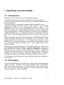
1. Selecting an LCD module ....................................................................... 5
1.1. Introduction .................................................................................... 5
1.2. Fluid types...................................................................................... 5
1.2.1. TN Fluid .................................................................................... 6
1.2.2. STN AND NTN Fluid................................................................. 6
1.3. Viewing modes............................................................................... 7
1.4. Backlightighting character modules................................................ 7
1.4.1. EL Backlighting......................................................................... 8
1.4.2. LED Backlighting ...................................................................... 8
1.5. Interface ......................................................................................... 9
1.5.1. Direct Interface ......................................................................... 9
1.5.2. SAPIC-E Interface .................................................................. 10
1.6. Mounting Suggestion ................................................................... 10
2. LCD software ......................................................................................... 11
2.1. Introduction .................................................................................. 11
2.2. Initialization .................................................................................. 11
2.3. 4-bit Operation ............................................................................. 12
2.4. Display Addressing....................................................................... 12
2.5. Specially Coded Displays............................................................. 13
2.6. Instruction Table........................................................................... 15
2.7. LCD Instruction Description.......................................................... 16
2.7.1. Clear Display .......................................................................... 16
2.7.2. Return Home .......................................................................... 16
2.7.3. Entry Mode Set....................................................................... 17
2.7.4. Display On/Off Control............................................................ 17
2.7.5. Cursor or Display Shift............................................................ 18
2.7.6. Function Set ........................................................................... 18
2.7.7. Set CG RAM Address............................................................. 18
2.7.8. Set DD RAM Address............................................................. 18
2.7.9. Read Busy Flag and Address................................................. 19
2.7.10. Write Data to CG RAM or DD RAM...................................... 19
2.7.11. Read Data from CG RAM or DD RAM.................................. 19
2.7.12. The Use of CG RAM............................................................. 20
3. SAPIC-E hardware................................................................................. 23
3.1. Introduction .................................................................................. 23
3.2. Demo mode.................................................................................. 23
3.3. Connectors................................................................................... 23
3.3.1. LCD ........................................................................................ 23
3.3.2. Backlight ................................................................................. 24
3.3.3. Contrast .................................................................................. 24
3.3.4. Power ..................................................................................... 24
3.3.5. Serial Line .............................................................................. 25
3.3.6. Keyboard ................................................................................ 26
3.4. Circuit diagram ............................................................................. 27
User's Manual Version 1.1 November 1, 1999
3
3.5. Board Outline................................................................................28
4. SAPIC-E software ..................................................................................29
4.1. SAPIC-E Commands ....................................................................29
4.1.1. Instruction Table .....................................................................29
4.1.2. Select Data .............................................................................29
4.1.3. Select Command ....................................................................29
4.1.4. Use E1 ....................................................................................29
4.1.5. Use E2 ....................................................................................30
4.1.6. Read LCD ...............................................................................30
4.1.7. Read Keyboard .......................................................................30
4.1.8. Resolving command conflict ...................................................31
4.2. Programming Example .................................................................32
4.3. Toubleshooting .............................................................................33
5. Instruction Summary.............................................................................33
4
SAPIC-E Small Alphanumeric LCD Controller
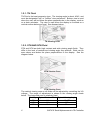
1. Selecting an LCD module
1.1. Introduction
Selecting an LCD module involves 3 basic design decisions.
1) What size and format is required to display the desired information.
2) What optical characteristics will look best in the package and attract the
user to the product.
3) What interface is most practical, and what additional benefits it has.
Densitron produces dot-matrix LCDs in two formats: fully functional
Alphanumeric Modules; and fully-populated Graphic modules.
This
application note is for use with the alphanumeric (A/N) or character type
modules. Alphanumeric modules display characters, numerals, symbols and
some limited graphics. Normally interface is achieved via a bi-directional,
parallel ASCII data bus. A more advanced interface is achieved via SAPIC-E
card, that controls backlight, keyboard and up to two A/N LCDs via serial
line.
Necessary features such as Character Generation, Display RAM Addressing,
Cursor Scrolling, Blanking, and Handshake are all included.
User
programmable fonts are supported. In summary, these modules are the
simplest and most economic means to communicate meaningfully between
any micro-system and the outside world. Their inclusion adds to any
product's appeal.
Alpha-numeric modules range from 8 to 80 characters per line. One, two or
four character lines may be chosen. Character height spans 0.130" (3.31
mm) to 0.500" (12.71 mm). Most formats are available in a variety of
packages to meet various mounting requirements. Multi-line models offer
the best value when analyzed by a "cost per character" basis. Displays are
readable both day and night by selecting a backlight option. Extended
temperature modules are available which operate between -20 and +70C.
The following sections explains the optical characteristic options available in
A/N modules.
1.2. Fluid types
The fluid type determines the contrast ratio, viewing angle, and temperature
range of an LCD. Densitron uses 3 basic classes of fluid, TN (Standard
type), NTN (high contrast type), and STN (premium high contrast type).
Many TN and NTN models are available in extended temperature range.
Contact Densitron for current availability.
User's Manual Version 1.1 November 1, 1999
5
1.2.1. TN Fluid
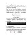
TN Fluid is the least expensive type. The viewing angle is about 40-45, and
must be designated "top" or "bottom" view preference. Bottom view is used
when the user will be below the plane perpendicular to the display, such as
on a desk calculator. Top view is used when the display is mounted on a
vertical surface below eye level. See diagram below.
TN Viewing Cone
1.2.2. STN AND NTN Fluid
STN and NTN are both high contrast and wide viewing angle fluids. They
differ in the level of contrast and viewing angle they achieve. Both can be
seen above and below the plane perpendicular to the display. See the
diagram below.
NTN Viewing Cone
STN Viewing Cone
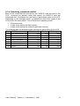
The vertical viewing cone on all fluids can be adjusted by controlling the VO
voltage. The range of adjustment is shown in the viewing angle charts
below. The horizontal cone is relatively fixed.
Fluid Type Typical Contrast Ratio Typical Viewing Angle
TN
3:1
40-45o
NTN
7:1
60o
STN
10:1
75o
6
SAPIC-E Small Alphanumeric LCD Controller
1.3. Viewing modes
The fluid type, polarizers and module construction determine the viewing
mode and colour of the display. Displays are either "postive image", dark
characters on a light background; or "negative image", light characters on a
dark background. Backlight capability is determined by the presence or
absence of a reflector or transflecter on the back side of the glass.
Reflective displays have a full reflector. The cannot be backlit. They offer
the lowest power option and the best contrast in high ambient light
conditions. They are not available in "positive image".
Transmissive displays are usually negative image and are backlit for best
readability. They can be used in well lit indoor conditions to dark
environments, typically not recommeded for daylight usage. They offer a
different appearance than typical LCDs, bringing a light emitting look to the
product.
Transflective displays combine the features of reflective and transmissive
modes. These positive image displays can be read in all lighting conditions.
The backlight can be turned on for low light levels or operated continuously
to add the light-emitting look to a product.
Positive Image
Negative Image
Colors
TN positive image displays will have a silver/grey background and dark,
almost black characters. In the negative image, the background will be black
and the characters will be the color of the backlight, usually yellow/green or
white. (See section on backlighting).
NTN and STN positive image displays can have a silver or yellow
background with dark characters. Negative image versions have a dark blue
background, characters are the folour of the backlight.
Choice of color is determined by what fits best in the package. Not all NTN
displays are available in all colors. Consult Densitron for current availability.
1.4. Backlightighting character modules
Backlighting is used on LCDs to make them readable in low light conditions.
Refer to the section on viewing modes for the types and applications of
display that are backlit. Densitron currently uses 2 methods to backlight
character LCD module: Electroluminescent (EL) and Light Emitting Diode
(LED). Selection depends on desired color, available power, and required
life.
User's Manual Version 1.1 November 1, 1999
7
1.4.1. EL Backlighting
EL backlighting is the original LCD backlight. It is thin, lightweight, low
power, and fits between the glass assembly and PCB without any
modification to the module. Most positive mode displays are furnished with a
blue green lamp. Negative mode displays usually come with a white lamp.
Other colors can be specially ordered.
EL lamps operate from an AC power source, typically 400Hz at 70-110 VAC.
Densitron supplies a full range of DC to AC inverters to power the lamps
from a +5VDC source. There is no hard and fast rule for matching an
inverter to a specific lamp.
Lamp brightness and life are inversely
proportional. That is the harder the lamp is driven the brighter it will be, but
the shorter the life. Under rated operating conditions lamp life is about 2,000
to 2,500 hours to half its original brightness. Operating conditions such as
temperature and humidity will also effect lamp life. The graph below
illustrates the brightness vs life curve.
TYPICAL EL LAMP LIFE
Recommended inverters for various sizes of modules are shown below.
Design considerations such as the operating conditions, desired brightness,
required light, and lamp life must be balanced when designing with EL
backlighting. For example, a negative transmissive display used in normal
room lighting may look better when driven with a larger inverter but useful life
will be shortened.
Inverter
Displays
DAS5V4 All A/N Displays except 4x40, 2x40, LM300 & LM4700 Series
DAS5V7 4x40, 2x40, LM300 & LM700 Series Transflective
DAS5V8 4x40, 2x40, LM300 & LM700 Series Transflective
Inverter Recommendations
1.4.2. LED Backlighting
LED backlighting offers a significant life advantage over EL lamps, but at the
sacrifice of power and module size. Lamp life is in excess of 50,000 hours,
and in most cases, 1 lamp failing does not make the backlight unusable.
LED backlit does not make the backlight unusable. LED backlit modules are
2-4mm thicker than an EL or non-backlit module. Standard color is yellowgreen. Red amber and other colors may be specially ordered.
8
SAPIC-E Small Alphanumeric LCD Controller
Edgelit Style
Array Style
LED Backlight Functional Diagram
Densitron offers two types of LED backlights; edgelit and array. Their basic
format is shown above.
Edgelit can be used on modules up to 20 characters wide. Beyond 20
characters, the middle of the display begins to dim when compared to the
edges. (The LM43X series uses a top mounted edgelight to achieve its
balance of light and power). Edgelight is the lower power of the two types.
The 4XXX series edgelit modules typically operate 30 to 60mA(at +5VDC)
and come with a built in current limit resistor. The 43X series is somewhat
higher and must have a limited resistor in series for proper operation.
Array backlighting produces a brighter and more even light. Power is the
main consideration when designing with this type of module. It is not
recommended for battery powered applications where the lamp will be on all
the time. (It may be suitable for "on demand" applications).
Limit resistors must be used for array backlit modules and the LM43X series.
Refer to the specific module specification for recommended and/or maximum
backlight ratings. LEDs are arranged in serial pairs and operated in parallel
(see diagram). The lamp will require 4.2VDC. Brightness can be set or
controlled by selecting the proper limit resistor. Select a resistor that will
drop the remaining voltage at the desired current. For example, if 200mA
produces the desired brightness and the supply voltage is +5VDC, the limit
resistor will drop 0.8VDC (5.0 - 4.2). Therefore, E/I = R = 0.8/0.2 - 4ohms.
1.5. Interface
Two interface methods can be usd to connect LCD to host system. In direct
connection the host system is responsible for creating all the signals for the
LCD. This requires good understanding of the LCD.
Connection via SAPIC-E interface card is much simpler, it is done via serial
line. Commands sent to the SAPIC-E are transferred to the LCD or
interpreted by the controller.
1.5.1. Direct Interface
A/N modules are an intelligent peripheral which can communicate, bidirectionally, within the master system. Tie the device into the system data
bus and treat it as RAM, I/O, or expanded, parallel I/O. The module is
"selected" by gating a decoded, "module-address" output, with the host
processor's "read or write" strobe. The resultant signal, applied to the LCDs
"enable" input, clocks in data. There is no conventional "chip-select".
Interfacing the module to an existing micro-system involves:
a) joining the module to the host's data bus.
b) developing a "strobe" signal for the "E" signal
c) applying appropriate signals to modules "RS" and "R/W"
d) applying the proper "viewing angle" voltage to the display's VO pin.
User's Manual Version 1.1 November 1, 1999
9
1.5.2. SAPIC-E Interface
Commands are sent to the SAPIC-E via standard serial line in either RS-232
or TTL level. These commands control the operation of the LCD, the
backlight, the software controlled contrast and the keyboard. Interfacing the
module to an existing micro-system involves is quite straightforward. Just
connect it to a standard free serial line.
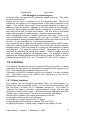
1.6. Mounting Suggestion
Care must be taken when mounting an LCD module to ensure that module is
not stressed when installed and the surface is not exposed to scratches or
harmful material.
Causing any kind of warp on the PCB of the module may product open
columns or rows of dots, or intermittent display. Presure on the bezel from
the top or against the bezel tabs will lead to similar problems.
The front surface of the module is a sensitive plastic polarizer, not glass.
Liquid must not be allowed to condense upon the device. Whenever
possible, install an optically correct "protection Barrier" between the outside
world and the display.
This should be a non-polarized plastic or
polycarbonate, which will reduce the incidence of foreign-object invasion and
static discharge into the display. To keep glare at a minimum, mount the
protective piece as close to the display surface as possible while preventing
pressure on the piece from being transmitted to the LCD. Non-glare
properties can be added to the protective piece at a slight loss of display
clarity.
Mounting Suggestion
10
SAPIC-E Small Alphanumeric LCD Controller
2. LCD software
2.1. Introduction
Software determines what, how and where data is displayed on the LCD. All
Densitron character modules feature the Hitachi HD44780 or equivalent
controller IC. This versatile chip features:
• Built-in character generator with 192 character modified ASCII
character set.
• Ability to program up to 8 custom characters.
• Bi-directional 8 or 4 bit bus interface
• 80 character RAM
• Automatic reset on power up
• Wide range of instruction functions including:
- Display clear, Cursor positioning, Display or cursor shift on data
entry, and Display ON/OFF
If the LCD is connected to the host system via SAPIC-E card additional
commands are available to control the backlight, the software contrast and
the keyboard. LCD instructions are explained in detail on the following
pages and the special SAPIC-E commands are explained in SAPIC-E
software section.
2.2. Initialization
The module has 2 registers; one for inputting instructions and one for
reading or writing data. Instructions are used to tell the module how and
where to put the data. If the rise time of the power supply meets the criteria
below, the module will default to the following functions via an internal
initialization routine:
• Clear Display
DL=1: 8 bits interface
• Function Set
N=0: 1 line display
F=0: 5x7 dot font
• Dislay ON/OFF control D=0: Display OFF
C=0: Cursor OFF
B=0: Blink OFF
I/O=1: +1 increment
• Entry Mode Set
• DD RAM is selected
The display will be busy for approximately 15mS after power ON.
Power Supply Timing Requirements for Internal Initialization
User's Manual Version 1.1 November 1, 1999
11
If power supply rise time cannot be assured of meeting the requirements
above, or if different parameters are required (such as for a 2 line display),
an initialization routine will have to be sent from the host. When first setting
up the display, Densitron recommends the following initialization routines for
8 bit interfaces:
• 1 line display with 5x7 font:
• 30H, 30H, 06H, 0EH, 01H
• 1 line display with 5x10 font:
• 34H, 34H, 06H ,0EH, 01H
• 2 line display with 5x7 font:
• 38H, 38H, 06H, 0EH, 01H
Wait states should be programmed to allow 15mS after power up before
initialization begins. Waiting 4.1mS between the "3X" codes and 100S after
the second "3X" code add a safety margin and ensure proper initialization.
After sending this routine, you should have a clear display with a flashing
cursor in the upper left position. The cursor will then increment to the right
with each data RAM write command. If, you do not have this display, see
Troubleshooting Tips in the appendix.
2.3. 4-bit Operation
The modules will operate from a 4-bit wide data bus. Data is transferred
over data lines D7-D4. D3-D0 may float. 8-bit hex code is sent one nibble at
a time, with the most significant nibble sent first. The function set in the
initialization routine must change to accommodate this mode.
A
recommended initialization routine is as follows:
2 line display with 5x7 font:
02H, 08H, 02H, 08H, 00H, 06H, 00H, 0EH, 00H, 01H
If SAPIC-E interface is used the LCD module is always programmed to 4-bit
operation.
2.4. Display Addressing
The display RAM is 8 characters. If the display is less than 80 characters,
what is on the screen is a "window" on the RAM. What is displayed depends
on the Entry Mode Set instruction. Address diagrams on the next page show
RAM addresses as they appear after a Clear Display or Return Home
instruction, or when Entry Mode Set instruction S=0.
If a 2-line display has less than 40 characters per line, the cursor will
advance off the screen after the last character of the first line. To put data
on the secone line, a Set DD RAM Address instruction must be sent.
When instruction S=1, the display is shifted. This makes the characters look
as though they are marching across the screen on entry. It also lets small
displays (2x16s, for example) to have data stored in non-visible areas of the
12
SAPIC-E Small Alphanumeric LCD Controller
RAM and shifted in to view with one command. The last diagram shows how
the addresses "wrap" in this mode.
Entire memory
1x40
1x24
1x20
1x16
1x8
80 … 87 88 … 8F 90 91 92 93 94 95 96 97 98 … A7 A8 ... CF
1 Line Display Addresses
Entire memory
2x40
2x24
2x20
2x16
2x8
80 … 87 88 … 8F 90 91 92 93 94 95 96 97 98 … A7
C0 … C7 C8 … CF D0 D1 D2 D3 D4 D5 D6 D7 D8 … E7
2 Line Display Addresses
Entire memory
2x40
2x24
2x20
2x16
2x8
81 … 88 89 … 90 91 92 93 94 95 96 97 98 99 … 80
C1 … C8 C9 … D0 D1 D2 D3 D4 D5 D6 D7 D8 D9 … C0
2 Line Display Addresses with Display Shifted Left
(I/D=1, S=1. See Entry Mode Set Instruction)
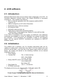
2.5. Specially Coded Displays
Three types of displays have different addressing than typical 1 or 2 line
displays. They are:
• 1 chip 1 line by 16 character displays
• 4 line by 16 or 20 character displays
• 4 line by 40 character displays
1 chip 1x16 - The HD44780 has the ability to control up to 16 characters
without any other driver ICs. A lower cost 1 line by 16 character display can
be manufactured to take advantage of this feature. To do this, it is
necessary to initialize the display in the 2 line mode. The display is then
addressed as a 2 line display. Line 1 addresses the first 8 characters; line 2,
the second 8. When the cursor gets to the ninth character of the first line, it
will "disappear" into undisplayed RAM (assuming no display shift). A Set DD
User's Manual Version 1.1 November 1, 1999
13
RAM Address must be sent to reposition the cursor to the ninth displayed
character which is logically the first position of the second line.
80 81 82 83 84 85 86 87 C0 C1 C2 C3 C4 C5 C6 C7
1 Chip 1 Line by 16 Character Addresses
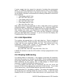
4x40 - The maximum capacity of the HD44780 is 80 characters. The 160
characters on the 4x40 displays are accessed with 2 controllers. The first
controller handles the top two lines; the second controller is conected to the
bottom two lines. They share all I/O lines except the "E". Logically, the
display is like two displays connected to the MPU as the "E" lines must be
independent. Remember to turn off the cursor when moving from one half of
the display to the other to avoid viewer distraction.
E1 used
E1 used
E2 used
E2 used
80
C0
80
C0
81
C1
81
C1
82
C2
82
C2
...
...
...
...
8F
CF
8F
CF
90
D0
90
D0
91
D1
91
D1
92
D2
92
D2
93
D3
93
D3
94
D4
94
D4
95
D5
95
D5
96
D6
96
D6
97
D7
97
D7
...
...
...
...
A5
E5
A5
E5
A6
E6
A6
E6
A7
E7
A7
E7
4 Line by 40 Character Addresses
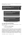
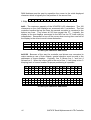
4x16/20 - Because of the way the controller and drivers are connected to
make maximum use of their outputs, special attention must be paid to the
addresses of these displays. Logically, line 3 follows line 1, and line 4
follows line 2. When the cursor gets to the end of line 1, it will jump to line 3.
Keeping track of cursor location for proper positioning is important.
80 81 82
C0 C1 C2
90 91 92
D0 D1 D2
83
C3
93
D3
84
C4
94
D4
85
C5
95
D5
86 87 88 89 8A
C6 C7 C8 C9 CA
96 97 98 99 9A
D6 D7 D8 D9 DA
8B
CB
9B
DB
8C 8D 8E 8F
CC CD CE CF
9C 9D 9E 9F
DC DD DE DF
4 Line by 16 Character Addresses
80
C0
94
D4
81
C1
95
D5
82
C2
96
D6
83
C3
97
D7
84
C4
98
D8
85
C5
99
D9
86
C6
9A
DA
87
C7
9B
DB
88
C8
9C
DC
89
C9
9D
DD
8A
CA
9E
DE
8B
CB
9F
DF
8C
CC
A0
E0
8D
CD
A1
E1
8E
CE
A2
E2
8F
CF
A3
E3
90
D0
A4
E4
91
D1
A5
E5
92
D2
A6
E6
93
D3
A7
E7
4 Line by 20 Character Addresses
14
SAPIC-E Small Alphanumeric LCD Controller
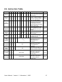
2.6. Instruction Table
Instruction RS RW D7 D6 D5 D4 D3 D2 D1 D0
Clear
Display
0
0
0
0
0
0
0
0
0
Return
Home
0
0
0
0
0
0
0
0
1
Entry
Mode Set
0
0
0
0
0
0
0
1
ID
Display
ON/OFF
Control
0
0
0
0
0
0
1
D
C
Cursor or
Display
Shift
0
0
0
0
0
1
SC RL
*
Function
Set
0
0
0
0
1
Set
CG RAM
Address
0
0
0
1
Set
DD RAM
Address
0
0
1
ADD
Read Busy
Flag &
0
Address
1
BF
AC
DL N
F
ACG
Write Data
to RAM
1
0
Write Data
Read Data
from RAM
1
1
Read Data
*
Description
Clears Display and returns
1 cursor to the Home Position
(Address 00)
Returns cursor to Home
Position. Returns shifted
*
display to original position.
Does not clear display
Sets DD RAM counter to
increment or decrement
S (ID) Specifies cursor or
display shift during to Data
Read or Write (S)
Sets Display ON/OFF (D),
cursor ON/OFF (C), and
B
blink character at cursor
position
Moves cursor or shifts the
* display w/o changing DD
RAM contents
Sets data bus length (DL), #
* of display lines (N), and
character font (F)
Sets CG RAM address. CG
RAM data is sent and
received after this
instruction
Sets DD RAM address. DD
RAM data is sent and
received after this
instruction
Reads Busy Flag (BF) and
address counter contents
Writes data to DD or CG
RAM and increments or
decrements address
counter (AC)
Reads data from DD or CG
RAM and increments or
decrements address
counter (AC)
User's Manual Version 1.1 November 1, 1999
Time
80us1.6ms
40us1.6ms
40us
40us
40us
40us
40uS
40uS
1uS
40uS
40uS
15
ID=1: Increment
S=1: Display Shift on data entry
SC=1: Display Shift (RAM unchanged)
RL=1: Shift to the Right
DL=1: 8 bits
N=1: 2 Lines
F=1: 5x10 Dot Font
D=1: Display ON
C=1: Cursor ON
B=1: Blink ON
BF=1: Cannot accept instruction
Definitions:
DD RAM: Display data RAM
CG RAM: Character generator RAM
ACG: CG RAM Address
ADD: DD RAM Address(Cursor Address)
AC: Address Counter used for both DD and
CG RAM Address
ID=0: Decrements
S=0: Cursor Shift on data entry
SC=0: Cursor Shift (RAM unchanged)
RL=0: Shift to the Left
DL=0: 4 bits
N=0: 1 Line
F=0: 5x7 Dot Font
D=0: Display OFF
C=0: Cursor OFF
B=0: Blink OFF
BF=0: Can accept instruction
Execution Time changes when Frequency
changes per the following example:
If FCP or fosc is 27 KHz
40uS x 250/270 = 37uS
* Don't Care
2.7. LCD Instruction Description
2.7.1. Clear Display
RS RW D7 D6 D5 D4 D3
0
0
0
0
0
0
0
D2 D1 D0
0
0
1
Writes space code 20H into all the DD RAM addresses. The cursor returns
to Address 0 (ADD=80H) and display, if it has been shifted, returns to the
original position. In other words, display disappears and the cursor goes to
the left edge of the display (the first line if a 2 or 4 line display module is
used).
2.7.2. Return Home
RS RW D7 D6 D5 D4 D3
0
0
0
0
0
0
0
* Don't Care
D2 D1 D0
0
1
*
Returns the cursor to Address 0 (ADD=80H) and display, if it has been
shifted, to the original position. The DD RAM contents remain unchanged.
16
SAPIC-E Small Alphanumeric LCD Controller
2.7.3. Entry Mode Set
RS RW D7 D6 D5 D4 D3
0
0
0
0
0
0
0
D2 D1 D0
1 ID S
ID: Increments (ID=1) or decrements (ID=0) the DD RAM address by one
when writing or reading a character code from DD RAM. The cursor moves
to the right when incremented by one. The same applies to writing and
reading CG RAM.
S: Shifts the entire display to either the right or the left when S is 1; to the left
when ID=1 and to the right when ID=0. Therefore, the cursor looks as if
stood stil while only the display has moved. Display is not shifted when
reading from DD RAM. Display is not shifted when S=0.
2.7.4. Display On/Off Control
RS RW D7 D6 D5 D4 D3
0
0
0
0
0
0
1
D2 D1 D0
D
C
B
D: Display is turned ON when D=1 and OFF when D=0. When display is
turned off due to D=0, the display data remains in the DD RAM and it can be
displayed immediately by setting D=1.
C: The cursor is displayed when C=1 and not displayed when C=0. Even if
the cursor disappears, function of I/D, etc. does not change during display
data write. The cursor is displayed using 5 dots in the 8th lines when the 5 x
7 dot character font is selected and in the 11th line when 5 x 10 dot
character font is selected.
B: The character residing at the cursor position blinks when B=1. The blink
is done by switching between all dots ON and display characters at 0.4
second interval. The cursor and the blink can be set concurrently.
Detached
Attached
Cursor Position
Blinking Character
User's Manual Version 1.1 November 1, 1999
17
2.7.5. Cursor or Display Shift
RS RW D7 D6 D5 D4 D3 D2 D1 D0
0
0
0
0
0
1 SC RL *
*
* Don't Care
Shifts the cursor position or display to the right or left without writing or
reading the display data. This function is used for correction or search of
display.
SC
0
0
1
1
RL
0
1
0
1
Shifts the cursor position to the left. (AC is decremented by one.)
Shifts the cursor position to the right. (AC is incremented by one).
Shifts the entire display to the left. The cursor follows the display shift.
Shifts the entire display to the right. The cursor follows the display shift.
2.7.6. Function Set
RS RW D7 D6 D5 D4 D3
0
0
0
0
1 DL N
* Don't Care
D2 D1 D0
F
*
*
DL: Sets interface data length. Data is sent or received in 8 bit length (DB7DB0) when DL=1 and 4 bit length (DB7-DB4) when DL=0. When 4 bit length
is selected, data must be sent or received in 2 operations.
N: Sets number of display lines.
F: Sets character font. (Together, N & F set the duty cycle).
2.7.7. Set CG RAM Address
RS RW D7 D6 D5 D4 D3
0
0
0
1
A
A
A
D2 D1 D0
A
A
A
Sets the CG RAM address in a binary number of AAAAAA to the address
counter, and data is written or read from the MPU related to the CG RAM
after this. This is used for programming the Character Generator (CG) RAM.
2.7.8. Set DD RAM Address
RS RW D7 D6 D5 D4 D3
0
0
1
A
A
A
A
D2 D1 D0
A
A
A
Sets the DD RAM address in a binary number of AAAAAAA in the address
counter. Data is written or read from the MPU related to the DD RAM after
this. When N=0 (1 line display), AAAAAAA is 00H to 47H. When N=1 (2 line
display),
AAAAAAA for the first line is 00H to 27H and 40H to 67H, for the second
line. Because the MSB is set to "1", the hex codes are actually 80H to C0H,
80H to A7H, and C0H to E7H respectively. See Display Addressing for more
information.
18
SAPIC-E Small Alphanumeric LCD Controller
2.7.9. Read Busy Flag and Address
RS RW D7 D6 D5 D4 D3
0
1 BF A
A
A
A
D2 D1 D0
A
A
A
When BF=1, the system is internally operating on a previously received
instruction. The next instruction will not be received until BF=0. The value of
the address counter also to read during this operation, and is given in binary
AAAAAAA. Whether CG or DD RAM address is read is determined by the
previous instruction.
2.7.10. Write Data to CG RAM or DD RAM
RS RW D7 D6 D5 D4 D3
1
0
D
D
D
D
D
D2 D1 D0
D
D
D
Writes binary 8 bit data DDDDDDD to the CG or the DD RAM. Whether the
CG or the DD RAM is to be written is determined by the previous designation
(CG RAM address setting or DD RAM address setting). After write, the
address is automatically incremented or decremented by one according to
entry mode. Display shift also follows the entry mode.
2.7.11. Read Data from CG RAM or DD RAM
RS RW D7 D6 D5 D4 D3
1
1
D
D
D
D
D
D2 D1 D0
D
D
D
Reads binary 8 bit data DDDDDDD from the CG or the DD RAM. Whether
the CG RAM or the DD RAM is to be read is determied by the previous
designation. Prior to inputting this read instruction, either the CG RAM
address set instruction or the DD RAM address set instruction must be
executed. If it is not done, the first read data becomes invalid, and data of
the next address is read normally from the second read. After read, the
address is automatically incremented or decremented by one according to
the entry mode. However, display shift is not performed regardless of entry
mode types.
User's Manual Version 1.1 November 1, 1999
19
2.7.12. The Use of CG RAM
Character Generator (CG) RAM is a useful accessory. It does not have to be
used or attended to during any normal display operation. CG RAM allows
the creation of up to 8 special character or symbols. Once programmed, the
newly formed characters may be accessed as if they were in the "normal"
CG ROM. This ROM contains 192 unchangeable characters. Thus the CG
RAM expands the character representation available to the user.
NOTE: This is a RAM, and must be reprogrammed if display power is
interrupted. If used regularly, programming can be made part of the
initialization routine.
There are two distinct areas of RAM within the display module. The main
area, 80 bytes wide, is dedicated to the display and is called Display Data
(DD) RAM. CG RAM consists of 64 bytes which range from 40 to 7F (hex),
or 4 5x10 (or 5x11) symbols. 40-47 locate the first, custom 5x7 character.
40 is the top row of this character, 47 is the 8th row. Similarly, 48-4F locate
the second CG character, and 78-7F locate the 8th custom character. The
locations 40-7F are the CG "Programming" locations only! Once
programmed, these special characters are displayed by writing to character
font locations 00-07 (hex). 00 will retun that character residing in locations
40-47, 01 returns 48-4F. etc. (See Font Chart).
While the CG RAM byte is 8 bits wide, only the 5 least significant bits appear
on the LCD. Thus D4 represents the left-most dot and D0 the right-most dot.
To illustrate, loading a CG RAM byte with 1F turns all dots in that row on;
loading a byte with 00 turns all dots off. All 7 or 8 rows must be programmed
at each desired CG location.
Programming procedure is:
a) with RS=0 enter the address of the top row of the character to be
programmed (i.e. 40,48,50, etc.)
b) with RS=1 enter pattern data for row 1 (top row)
c) continue to enter pattern data for rows 2-8; it is not necesary to enter
additional addresses if the module has been initialized with command 06
(auto increment of cursor). This procedure may be continued until all CG
bytes have been loaded.
The CG RAM can create an attractive, "reverse-video" 3 x 5 pattern.
Numerals look especially good in this format. Most letters can be executed.
The limitation of 8 characters can be circumvented by creating a "library" of
custom symbols, each totalling 8, resident in the host system. Eight custom
symbols can be displayed at any ONE time. The CG RAM can be
periodically reloaded as display requirements change. If you reload a CG
location which is currently on the display, the change will be immediately
apparent. Displays employing multiple controllers (ie. 4 x 40, 2 x 80. 4 x 80)
may create 8 symbols per controller. The CG RAM adds interest and
flexibility to the LCD module.
20
SAPIC-E Small Alphanumeric LCD Controller
CG RAM, DD RAM, and pattern examples for 5x7 dot patterns
Character Codes CG RAM Address Character Patterns
(DD RAM Data)
(CG RAM Data)
76543210
543210
43210
000000
11110
000001
10001
000010
1 0 0 0 1 - Character
000011
1 1 1 1 0 - Pattern
0000*000
000100
1 0 1 0 0 - Example (1)
000101
10010
000110
10001
000111
0 0 0 0 0 - Cursor Position
001000
10001
001001
01010
001010
1 1 1 1 1 - Character
001011
0 0 1 0 0 - Pattern
0000*001
001100
1 1 1 1 1 - Example (2)
001101
00100
001110
00100
001111
0 0 0 0 0 - Cursor position
*Don't Care
Notes:
a) Character code bits 0-2 correspond to CG RAM address bits 3-5 for a
total of 8 patterns.
b) CG RAM address codes 0-2 designate character pattern line. The 8th
line is the cursor position. It is logically "OR'ed" with the cursor
instruction.
c) Character patterns are loaded into CG RAM data bits 0-4 as shown in the
table. (Bit 4 is the left side). Since CG RAM bits 5-7 are not used, they
may be used for general data RAM.
d) CG RAM patterns are displayed on the LCD when character code bits 4-7
are all "0". Bit 3 is a don't care bit. Therefore, character pattern (1) can
be selected with character code 00H or 08H.
e) "1" in the character pattern turn a dot "ON". "0" indicates a non-selected
dot.
User's Manual Version 1.1 November 1, 1999
21
CG RAM, DD RAM, and pattern examples for 5x10 dot patterns
Character Codes
Character Patterns
CG RAM Address
(DD RAM Data)
(CG RAM Data)
76543210
543210
43210
000000
00000
000001
00000
000010
10110
000011
1 1 0 0 1 - Character
000100
1 0 0 0 1 - Pattern
0000*00*
000101
1 0 0 0 1 - Example (1)
000110
11110
000111
10000
001000
10000
001001
10000
001010
0 0 0 0 0 - Cursor Position
*Don't Care
Notes:
a) Character code bits 1 & 2 correspond to CG RAM address bits 4 & 5 for a
total of 4 patterns.
b) CG RAM address codes 0-3 designate character pattern line. The 11th
line is the cursor position. It is logically "OR'd" with the cursor instruction.
Since lines 12-16 are not used for the display, they may be used as
general data RAM.
c) Character patterns are loaded into CG RAM data bits 0-4 as shown in the
table. (Bit 4 is the left side). Since CG RAM bits 5-7 are not used, they
may be used for general data RAM.
d) CG RAM patterns are displayed on the LCD when character code bits 4-7
are all "0". Bits 0 & 3 are a "don't care" bits. Therefore, character pattern
(1) can be selected with character code 00H, 01H, 08H, 09H.
e) "1" in the character pattern turn a dot "ON". "0" indicates a non-selected
dot.
22
SAPIC-E Small Alphanumeric LCD Controller
3. SAPIC-E hardware
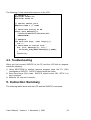
3.1. Introduction
SAPIC-E can interface most small alphanumeric LCDs, that uses the Hitachi
HD44780 chip, to PC or other type of computer. It has the following
features:
• Software compatible with other SA cards.
• Support for 1 or 2 controller LCDs.
• Small keyboard interface (max. 4x4 keys).
• Serial quasi RS-232 interface.
• Jumper selectable baud rates (2400, 9600)
• No external power supply is required.
• Demo mode
3.2. Demo mode
SAPIC-E works in demo mode it the baud rate jumper is left unconnected. In
this mode the keypresses on a 3x4 key telephone keypeds are echoed on a
2x16 LCD.
3.3. Connectors
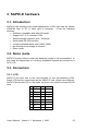
3.3.1. LCD
SAPIC-E can drive one or two one-controller or one two-controller LCDs.
Some LCD has the same pinout as the SAPIC-E card, others have different.
SAPIC-E drives the LCD in 4 bit mode, so there is no need to connect D0-D3
lines.
# Name
# Name
1 GND
2 +5V
3 VO
4 RS
5 R/-W
6 E1
7 NC (D0) 8 NC (D1)
9 NC (D2) 10 NC (D3)
11 D4
12 D5
13 D6
14 D7
15 E2
16 E2
User's Manual Version 1.1 November 1, 1999
23
3.3.2. Backlight
SAPIC-E can directly drive a LED backlight, or supply power for external
inverter for CFL backligh.
The LED backlight shall be connected to the backlight connector observing
polarity. By default two 100 ohm resistor are installed in parallel.
After shorting the current limiting resistors an inverter for CFL backlight can
be connected to the backlight connector.
3.3.3. Contrast
Most LCD requires a VO voltage between 0 and +5V. Others require VO
voltage to be between -5V and +5V. SAPIC-E supports only the former. The
best value depends on the LCD type and the temperature, therefore
adjustments are often needed.
There are four ways of controlling the contrast:
• Using the internal trimmer.
It is the most common way of setting the optimal contrast.
• Using an external potmeter connected to the contrast connector.
Changing the contrast by external potmeter is convenient when the card
operates at widely varying temperature.
• Setting a fixed value.
In cost sensitive applications, two SMD resistor can be installed instead of
the trimmer.
3.3.4. Power
SAPIC-E can generate its power from the DTR line, if backlight is not used,
or 5V (±20%) power can be supplied on either of the connector. SAPIC-E is
a low power device. Without LCD it consumes less than 1mA typical.
24
SAPIC-E Small Alphanumeric LCD Controller
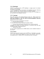
3.3.5. Serial Line
Either RS-232, or inverted TTL serial signals can be used. The RS-232 or
the inverted TTL signals should be connected to RXD and TXD pins. The
DTR and RTS signals can be used to supply power to SAPIC-E and the
LCD. The DTR and RTS signals, when high, can supply power for the
SAPIC-E card and the LCD, but not for the backlight. Sometimes additional
+5V power is required for the LCD.
# Name Description
1 GND
Ground
2 RXD
RS-232 PC receive, SAPIC-E transmit data
3 TXD
RS-232 PC transmit, SAPIC-E receive data
4 DTR
Power
5 RTS
Power
Standard RS-232 cable connection between PC and SAPIC-E:
1
2
3
4
5
GND
RXD
TXD
DTR
RTS
1
2
3
4
5
6
7
8
9
DCD
RXD
TXD
DTR
GND
DSR
RTS
CTS
RI
The baud rate is jumper selectable by a small jumper at the solder side of
the card. The format is always 8 data bits, 1 stop bit, no parity.
Jumper
Baud rate
2400 side connected
9600 baud
9600 side connected
4800 baud
Unconnected
Demo mode
The RS-232 interface is not fully RS-232 compatible, it cannot drive long
cables.
User's Manual Version 1.1 November 1, 1999
25
3.3.6. Keyboard
SAPIC-E directly supports a 4x4 keyboard, and via expansion registers a
60x4 keyboard. The additinal key are connected via HC164 shift registers.
One HC164 shift register is required for each 8x4 keyfield. Max. 7 HC164
can be used. The maximum number of keys are 240. Two connector type is
used: simple and extended. The simple connector supports only the first 16
keys, the extended one the first 48 keys. Both connector type can be further
extended by using additional shift registers.
Keyboard connector
#
1
3
5
7
9
26
Name
#
COLUMN0 2
COLUMN2 4
ROW0
6
ROW2
8
GND
10
Name
COLUMN1
COLUMN3
ROW1
ROW3
+5V
SAPIC-E Small Alphanumeric LCD Controller
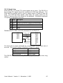
User's Manual Version 1.1 November 1, 1999
GND
4M H z
GND
VO
VCC
4 7 0k
R2
GND
VCC
VCC
R10
R 11
CFG
15
4
14
17
18
1
2
3
16
RB0
RB1
RB2
RB3
RB4
RB5
RB6
RB7
1k
-
RS
RW
KB1
KB0
E1
E2
RXTTL
TXTTL
C on figu ration
JP 1
E1
1
9600
CFG 2
3
E2
2400
B au d ra te
5
6
7
8
9
10
11
12
13
J4
1
VCC
2
VO
3
GND
POT
P IC 1 6 C 5 4 B
O SC2
MCLR
VCC
GN D
RA0
RA1
RA2
RA3
T0C K I
O SC1
U1
S A P IC -E L C D c o n tro lle r
X1
D4
D5
D6
D7
CFG
RX TTL
TX TTL
47k
R 1C
KB0
RW
D7
1k
1k
1k
1k
4 7k
1
3
5
7
1
3
5
7
9
11
13
15
R1D
R9A
RD95C
R8A
R8C
GND
VO
RW
D0
D2
D4
D6
E2
T2
NPN
R1B
47 k
R1A
47 k
SA LCD
RXD
TXD
J3
C0
C2
R0
R2
SA KEYBOAR D
J2
GND
VO
RW
D0
D2
D4
D6
E2
R5
4k7
T1
PNP
DTR
2
4
6
8
2
4
6
8
10
12
14
16
R 9B
R 9D
RK 8BB1
R 8D
E2
VCC
RS
E1
Z1
5V 1
1o f 1
S h eet:
8 0 -0 1 6 7
C1
C3
R1
R3
VCC
RS
E1
D1
D1
D3
D3
D5
D5
D7
D7
E2
VCC
GND
RXD
TX D
DTR
RT S
1k
1k
1k
1k
C1
4u7
GND
DTR
RT S
0 7 /2 3 /1 9 9 9
V 1 .1
RS
D6
D4
470
470
R6
R7
J1
GND
RXD
TX D
DTR
RT S
S A S E R IA L P O RT
1
2
3
4
5
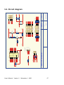
3.4. Circuit diagram
27
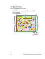
3.5. Board Outline
SAPIC-E is available in three versions:
• Card form
• Evaluation version with 3x4 key keypad and 2x16 LCD
• DIP chip version
• SOIC chip version
28
SAPIC-E Small Alphanumeric LCD Controller
4. SAPIC-E software
4.1. SAPIC-E Commands
In addition to the LCD commands that are directly passed to the HD44780
LCD controller, SAPIC-E has an additional commands.
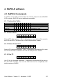
4.1.1. Instruction Table
Instruction
Select Data
Select Command
Use E1
Use E2
Read LCD
Read Keyboard
D7 D6 D5 D4 D3 D2 D1 D0 Description
0 0 0 0 1 0 0 0 Select LCD data register
0 0 0 0 1 0 1 0 Select LCD command register
0 0 0 1 0 0 1 0 Use E1 in the following instructions
0 0 0 1 1 0 1 0 Use E2 in the following instructions
0 0 0 0 1 0 0 1 Read data from LCD
0 0 0 1 1 0 0 1 Read keyboard code
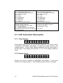
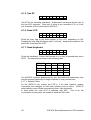
4.1.2. Select Data
D7 D6 D5 D4 D3 D2
0
0
0
0
1
0
D1 D0
0
0
Select LCD data registers. RS=1. Subsequent commands will be send to
the LCD with RS=1, therefore the LCD will interpret them as data.
4.1.3. Select Command
D7 D6 D5 D4 D3 D2
0
0
0
0
1
0
D1 D0
1
0
Select LCD command registers. RS=0. Subsequent commands will be sent
to the LCD with RS=1, therefore the LCD will interpret them as data.
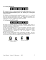
4.1.4. Use E1
D7 D6 D5 D4 D3 D2
0
0
0
1
0
0
D1 D0
1
0
Use E1 for the following operations. Subsequent commands will be sent to
the first LCD controller. You can use 1BH code too for compatibility with
earlier versions of SAPIC.
User's Manual Version 1.1 November 1, 1999
29
4.1.5. Use E2
D7 D6 D5 D4 D3 D2
0
0
0
1
1
0
D1 D0
1
0
Use E2 for the following oparations. Subsequent commands will be sent to
the first LCD controller. Used only if either a two controller LCD, or if two
one-controller LCD is connected to SAPIC-E.
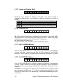
4.1.6. Read LCD
D7 D6 D5 D4 D3 D2
0
0
0
0
1
0
D1 D0
0
1
Read the busy flag or the data register of the LCD, depending on RS.
Reading the busy flag will always return "not busy", because the speed of the
serial line is less than the LCD.
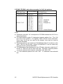
4.1.7. Read Keyboard
D7 D6 D5 D4 D3 D2
0
0
0
1
1
0
D1 D0
0
1
Check the keyboard. Return the keycode or if no key is pressed then return
0FFH. The keycodes are lised in the following table:
COLUMN
ROW0
ROW1
ROW2
ROW3
0
1
2
001H 002H 003H
005H 006H 007H
009H 00AH 00BH
00DH 00EH 00FH
3
004H
008H
00CH
010H
The SAPIC-E software debounces the key, but additional debouncing may
also be required especially for larger matrices in noisy environment.
4.1.7.1. Special Codes
As the SAPIC-E can access the LCD in 4 bit wide interface modes,
commands that changes to 8-bit wide interface has no effect. SAPIC-E
automatically convert these commands to their 4-bit equivalent.
In data mode the code 0FH is replaced with 00H. This is for the
convenience of users who are unable to send the 00H code.
30
SAPIC-E Small Alphanumeric LCD Controller
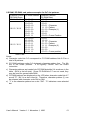
4.1.8. Resolving command conflict
Most of the codes that are received by the SAPIC-E card are sent to the
LCD. However the special codes that control the SAPIC-E card are
interpreted first. Sometimes the user want to send these codes to the LCD.
Depending on the operating mode it is possible to send other codes to the
LCD to have the same effect. The LCD has three operating mode:
• Command mode
• In data mode writing the data memory
• In data mode writing the character generator memory
The following table list alternate codes that has the same effect on the LCD.
Code SAPIC-E command
LCD command LCD data LCD char. gen.
00H User defined char. #0
00H
0FH
80H
08H Select data
0BH
00H
88H
09H Read data
0BH
01H
89H
0AH Select command
0BH
02H
8AH
12H Use E1
10H
10H
92H
19H Read keys
18H
10H
98H
1AH Use E2
18H
10H
9AH
User's Manual Version 1.1 November 1, 1999
31
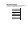
4.2. Programming Example
Assuming that a 16x2 LCD is connected to the SAPIC-E the following code
sequence will write the text "DENSITRON" to the first line of the LCD. You
can send the codes to the SAPIC-E by any terminal program.
0AH
12H
28H
01H
12H
0CH
08H
44H
45H
4EH
53H
49H
54H
52H
4FH
4EH
32
Command mode
Use E1
2 lines 5x7 dots
Clear display
No operation, (use E1)
Display on, no cursor
Data mode
Letter 'D'
Letter 'E'
Letter 'N'
Letter 'S'
Letter 'I'
Letter 'T'
Letter 'R'
Letter 'O'
Letter 'N'
SAPIC-E Small Alphanumeric LCD Controller
The following C code sends this sequence to the LCD:
// example.c
#include <stdio.h>
#include <bios.h>
// Define serial port
#define PORT 1 // COM2
// Send this string to SA
const char message[]=
"\x0A\x12\x28\x01\x12\x0C\x08"
"DENSITRON";
// Example
int main(int argc, char *argv[]){
int i;
// Send data to serial line
for (i=0; message[i]; i++){
bioscom(_COM_SEND,message[i],PORT);
}
return(0);
}
4.3. Toubleshooting
When you first connect SAPIC-E to the PC and the LCD fails to respond,
check the following:
1) Using SPLITCOM or another terminal program send Use E1 (12H)
commands to SAPIC-E. SAPIC-E should echo the codes.
2) Send Read keys (19H) code. SAPIC-E should return 19H, 0FFH if no
key is pressed.
3) Measure VO, and set it correctly.
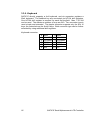
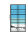
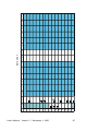
5. Instruction Summary
The following tables show both the LCD and the SAPIC-E commands.
User's Manual Version 1.1 November 1, 1999
33
34
SAPIC-E Small Alphanumeric LCD Controller
F
E
D
C
B
A
9
8
7
6
5
4
3
2
1
0
1
D isplay
off
D isplay
on
C ursor
blink
C ursor
line
C ursor
line blink
Select
R ead
dots
dots
dots
2
dots
1 line,
5x11 dots
1 line,
5x11 dots
1 line,
5x11 dots
1 line,
5x11 dots
2 lines,
5x7 dots
2 lines,
R ead
5x7 dots
2 lines,
U se E2
5x7 dots
2 lines,
R eser5x7 dots
S h ift right 2 lines,
5x7 dots
2 lines,
R eser5x7 dots
2 lines,
R eser5x7 dots
2 lines,
R eser5x7 dots
U se E1
C ursor
left
R eser-
C ursor
left
A uto cur- C ursor
sor left
right
A uto shift R eserleft
A uto cur- R esersor right
A uto shift C ursor
right
right
S h ift left
Select
H om e
C lear
display
H om e
0
dots
1 line,
5x11 dots
1 line,
5x11 dots
1 line,
5x11 dots
1 line,
5x11 dots
2 lines,
5x7 dots
2 lines,
5x7 dots
2 lines,
5x7 dots
2 lines,
5x7 dots
2 lines,
5x7 dots
2 lines,
5x7 dots
2 lines,
5x7 dots
2 lines,
5x7 dots
dots
dots
dots
3
4
CG RAM
address
5
6
7
DD RAM
address
8
C om m and m ode
9
A
B
C
D
E
F
User's Manual Version 1.1 November 1, 1999
35
F
E
D
C
B
A
9
8
7
6
5
4
3
2
1
0
0
S am e as
00
U se E2
Select
R eser-
R eser-
R eser-
R eser-
R ead
R eser-
R eser-
U se E1
R eser-
1
R ead
Select
U ser
defined
2
C ha racters
3
4
5
6
7
8
D ata m ode
9
A
C haracters
B
C
D
E
F