1
SGI01
Small Graphics
LCD Interface
User's Manual
Densitron International plc. 1998
Contents
Contents........................................................................................................ 3
1. Introduction ............................................................................................. 5
2. Interface ................................................................................................... 5
2.1. RS-232 interface ............................................................................ 6
2.2. I2C interface ................................................................................... 7
2.2.1. Bit Transfer............................................................................... 7
2.2.2. Start and Stop Conditions......................................................... 7
2.2.3. System configuration ................................................................ 8
2.2.4. Acknowledge ............................................................................ 8
2.2.5. Timing Specification ................................................................. 8
2.2.6. Addressing................................................................................ 8
3. LCD connection..................................................................................... 10
3.1. Connecting LCDs with built-in T6963 ........................................... 11
3.2. Connecting LCDs with built in HD61830 ...................................... 12
3.3. Connecting LCDs with built in HD61202 ...................................... 13
3.4. Power supplies and contrast control ............................................ 14
3.5. Backlights..................................................................................... 15
4. Software description............................................................................. 16
4.1. DefineLCD command................................................................... 16
4.2. SetMode command ...................................................................... 17
4.3. SetColor command ...................................................................... 18
4.4. MoveTo command ....................................................................... 18
4.5. MoveRel command ...................................................................... 18
4.6. SetBacklight command ................................................................ 19
4.7. FillScreen command .................................................................... 19
4.8. PutPixel command ....................................................................... 19
4.9. GetPixel command....................................................................... 20
4.10. LineTo command ....................................................................... 20
4.11. LineRel command ...................................................................... 20
4.12. Rectangle command .................................................................. 21
4.13. FillRectangle command.............................................................. 21
4.14. Circle command ......................................................................... 22
4.15. FillCircle command..................................................................... 22
4.16. SelectFont command ................................................................. 23
4.17. SetTextAttribute command......................................................... 24
4.18. PutChar command ..................................................................... 25
4.19. PutText command ...................................................................... 25
4.20. GetStringWidth command .......................................................... 26
4.21. PutBitmap command.................................................................. 26
4.22. GetBitmap command ................................................................. 27
4.23. DirectCommandWrite command ................................................ 27
4.24. DirectDataWrite command ......................................................... 28
4.25. DirectStatusRead command ...................................................... 28
4.26. DirectDataRead command......................................................... 28
4.27. DirectChipselect command ........................................................ 29
User's Manual Version 2.4 February 20, 1998
3
4.28. Echo command...........................................................................29
5. Built-in demo..........................................................................................30
5.1. Demo keys....................................................................................30
6. Part numbering ......................................................................................30
Appendix A: DIP switch settings ...............................................................31
Appendix B: Command summary .............................................................32
4
SGI01 Small Graphics LCD Interface
1. Introduction
The SGI01 card is a serial interface card designed to control a wide range of
Densitron small graphic Liquid Crystal Display (LCDs max 256x256 pixels)
modules. It has been designed to ease the implementation of an LCD
screen interface whilst maximizing the number of features and functions. It
has two user selectable interfaces; an RS-232 and an I2C interface for simple
interfacing to the host system. An extensive set of standard graphic drawing
instruction is also included as well as a useful set of text fonts and character
attributes. The instruction set allow the user to draw complicated graphics
using a basic set of drawing instructions, such as lines, circles. boxes, areafill and bit-mapped graphics.
The SGI01 supports three different LCD Graphics Controllers, namely the
T6963, HD61830 and HD61202. The SGI01 provides all the necessary
signals and voltages to interface to most LCD modules using either of these
three controller chips.
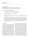
2. Interface
There are two interfaces on the SGI01 card: the RS-232 and the I2C
interface. They are DIP switch selectable. The location of the DIP switch,
the RS-232 interface connector and the I2C interface connector is shown in
the following picture:
R S -2 3 2 inte rface co nn e cto r
O p tion a l R S -2 32 in terfa ce co n ne cto r
I2C in te rfa ce con n ec to r
D IP sw itch
Dipswitch
Description
1xxx xxx1
Serial line is used
0xxx xxx1
I²C interface is used
If SW1-1 is off then the RS-232 interface is used, if SW1-1 is on then the I2C
interface is used. SW1-2 - SW1-4 determines the baud rate or the I2C
address.
User's Manual Version 2.4 February 20, 1998
5
2.1. RS-232 interface
The RS-232 interface can receive and transmit and uses the DSR and DTR
signals for hardware handshake.
DTR is used to control the input data flow of the SGI01. DTR is set if less
than third of the input FIFO is used. DTR is cleared if there are less than
third of the input FIFO is free. The host should suspend transmission when
DTR is cleared.
DSR is used the control the output data flow of the SGI01. When DSR is
cleared then the SGI01 card does not try to send.
The pinout of the RS-232 interface connector is the following:
Number
2
3
4
5
6
Name
RxD
TxD
DTR
GND
DSR
Description
Receive data
Transmit data
Input flow control signal
Ground
Output flow control signal
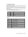
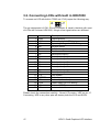
The format is 8 bit, no parity, one stop bit. The baud rate is DIP switch
selectable.
Dipswitch
1000 0xx1
1001 0xx1
1010 0xx1
1011 0xx1
1100 0xx1
1101 0xx1
1110 0xx1
1111 0xx1
1000 1xx1
1001 1xx1
1010 1xx1
6
Description
150 baud serial line
300 baud serial line
600 baud serial line
1200 baud serial line
2400 baud serial line
4800 baud serial line
19200 baud serial line
9600 baud serial line
38400 baud serial line
57600 baud serial line
115200 baud serial line
SGI01 Small Graphics LCD Interface
2.2. I2C interface
The I2C bus is a 2-way, 2-line communication between different ICs or
modules. The two lines are a serial data line (SDA) and a serial clock line
(SCL). Both lines must be connected to a positive power supply via a pull-up
resistor. Data transfer may be initiated only when the bus is not busy.
The pinout of the I2C interface connector of the SGI01 card is the following:
Number
1
2
3
4
Name
+5V
SDA
SCL
GND
Description
Power supply
Serial data
Serial clock
Ground
The pull-up resistors are R14 and R15.
disconnecting the pull-up resistors.
J15 and J16 jumpers allow
2.2.1. Bit Transfer
One data bit is transferred during
each clock pulse. The data on
SDA line must remain stable
during the HIGH period of the
clock pulse as changes in the
data line at this time will be
interpreted as control signals.
SD A
SC L
data line
stable;
data valid
change
of data
allow ed
2.2.2. Start and Stop Conditions
Both data and clock lines remain HIGH
when the bus is not busy. A HIGH-toLOW transition of the data line, while the
clock is HIGH is defined as the start
condition (S). A LOW-to-HIGH transition
of the data line while the clock is HIGH is
defined as the stop condition (P).
SD A
SC L
User's Manual Version 2.4 February 20, 1998
S
P
start condition
stop c ondition
7
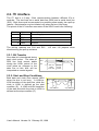
2.2.3. System configuration
Various devices can be connected to a
small area network as shown in the figure.
A device generating a message is the
"transmitter", a device receiving a
message is the "receiver". The device
that controls the message is the "master"
and devices controlled by the "master" are
the "slaves". The SGI01 card can work in
slave transmitter and receiver mode.
S la ve
tran sm itter
re ceiver
M a ster
tran sm itter
M a ste r
tran sm itter
re ceiver
S lave
re ceive r
SDA
SCL
2.2.4. Acknowledge
The number of
data bytes transSC L from m as ter
1
2
8
9
ferred between the
SD A from trans m itter
start and stop conD0
D7
D6
ditions from transSD A from rec eiver
AC K
mitter to receiver
S
P
is
not
limited.
Each byte is followed by one acknowledge bit. The acknowledge bit is a HIGH level put on
the bus by the transmitter whereas the master generates an extra
acknowledge related clock pulse. The device that acknowledges has to pull
down the SDA line during the acknowledge clock pulse, so that the SDA line
is stable LOW during the HIGH period of the acknowledge related clock
pulse.
2.2.5. Timing Specification
The SGI01 I2C interface operates only in high-speed mode. See I2C-bus
Specification, Signetics, March 1989 or some other Phillips/Signetics
catalogue for details.
2.2.6. Addressing
Before any data is transmitted on the I2C bus, the device which should
respond is addressed first. The addressing is always done with the first byte
transmitted after the start condition.
8
SGI01 Small Graphics LCD Interface
The upper 4 bits of the SGI01 card is always 0111B. Three other bits are
defined by the SW1-2 - SW1-4 DIP switches, and the less significant bit
determines the read or write operation. The resulting addresses are in the
following table.
Dipswitch
0000 xxx1
0001 xxx1
0010 xxx1
0011 xxx1
0100 xxx1
0101 xxx1
0110 xxx1
0111 xxx1
Description
I²C write address 70H, read address 71H
I²C write address 72H, read address 73H
I²C write address 74H, read address 75H
I²C write address 76H, read address 77H
I²C write address 78H, read address 79H
I²C write address 7AH, read address 7BH
I²C write address 7CH, read address 7DH
I²C write address 7EH, read address 7FH
The SGI01 always acknowledges its write address. Then the master can
send any number of command and data bytes. The SGI01 will acknowledge
each data bytes that it can receive. If the input FIFO of the SGI01 is full then
the SGI01 will not acknowledge that byte. Then the master either keep
repeating the byte until it is acknowledged or generate a stop condition.
S 0 1 1 1
sw1 2-4
0 A
com m and ordata
A P
C an be repeated any tim es
The SGI01 acknowledges its read address only if it has anything to send. If
the SGI01 acknowledged the read address then the master can receive one
data byte, generate an acknowledge and either a repeated start condition or
a stop condition. To read the next byte the master must address the SGI01
again. The SGI01 does not check the acknowledge at the and of the data
byte.
S 0 1 1 1
sw1 2-4
1 A
r e a d
d a t a
A P
C an be repeated if the S G I-01 ac knowledges its addres s
User's Manual Version 2.4 February 20, 1998
9
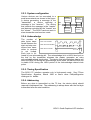
3. LCD connection
The SGI01 can control LCDs with built-in T6963, HD61830 or HD61202
controller IC. LCDs with built-in controller are connected to CN1 connector
of SGI01:
-Vee p in se le ct
LC D con n ecto r
J7-J8 jumpers select the function of pin 17 and 18:
P in 1 7
CE2
-Ve e
P in 1 8
Check these jumper settings carefully, because connecting -VEE incorrectly
will destroy both the LCD and SGI01.
10
SGI01 Small Graphics LCD Interface
3.1. Connecting LCDs with built-in T6963
To connect an LCD with built-in T6963 set J7-J8 jumper the following way:
J8
J7
The pin assignment of CN1 20-way connector is usually identical with most
of LCDs with on-board T6963.
Number
1
2
3
4
5
6
7
8
9
10
11
12
13
14
15
16
17
Name
GND
VCC
VO
C/-D
-WR
-RD
D0
D1
D2
D3
D4
D5
D6
D7
-CE
-RESET
(MD2)
18 -VEE
19 (FS1)
20 NC
Description
Logical ground
Power supply for LCD driving
Operating voltage for LCD driving
Command / data select
Write signal
Read signal
Data input/output 0
Data input/output 1
Data input/output 2
Data input/output 3
Data input/output 4
Data input/output 5
Data input/output 6
Data input/output 7
Chip enable
Controller reset
Columns select on certain type of LCDs
(Driven low here)
Power supply for LCD driving
Font select in certain type of LCDs
(Connected to GND here)
Not connected
Please check the connection carefully. Some LCD require -VEE on pin 17.
Connecting -VEE to any other pins will destroy both the LCD and SGI01.
User's Manual Version 2.4 February 20, 1998
11
3.2. Connecting LCDs with built in HD61830
To connect an LCD with built-in T6963 set J7-J8 jumper the following way:
J8
J7
The pin assignment of CN1 20-way connector is usually identical with most
of LCDs with on-board HD61830, though a few signal names are different.
Number
1
2
3
4
5
6
7
8
9
10
11
12
13
14
15
16
17
18
19
20
Name
GND
VCC
VO
RS
R/-W
E
D0
D1
D2
D3
D4
D5
D6
D7
-CE
-RESET
NC
-VEE
NC
NC
Description
Logical ground
Power supply for LCD driving
Operating voltage for LCD driving
Register select
Read/write signal
Enable
Data input/output 0
Data input/output 1
Data input/output 2
Data input/output 3
Data input/output 4
Data input/output 5
Data input/output 6
Data input/output 7
Chip enable
Controller reset
Not used (driven low)
Power supply for LCD driving
Not used (GND)
Not connected
Please check the connection carefully. Some LCD require -VEE on pin 17.
Connecting -VEE to any other pins will destroy both the LCD and SGI01.
12
SGI01 Small Graphics LCD Interface
3.3. Connecting LCDs with built in HD61202
To connect an LCD with built-in T61202 set J7-J8 jumper the following way:
J8
J7
The pin assignment of CN1 20-way connector is usually identical with most
of LCDs with on-board HD61202, though a few signal names are different.
Number Name
Description
1 GND
Logical ground
2 VCC
Power supply for LCD driving
3 VO
Operating voltage for LCD driving
4 RS
Register select
5 R/-W
Read/write signal
6 E
Enable
7 DB0
Data input/output 0
8 DB1
Data input/output 1
9 DB2
Data input/output 2
10 DB3
Data input/output 3
11 DB4
Data input/output 4
12 DB5
Data input/output 5
13 DB6
Data input/output 6
14 DB7
Data input/output 7
15 -CS1
Chip select 1
16 -RESET
Controller reset
17 -VEE
Power supply for LCD driving
18 -CS2
Chip select 2
19 NC
Not used (GND)
20 NC
Not connected
Please check the connection carefully. Some LCD require -VEE on pin 18.
Connecting -VEE to any other pins will destroy both the LCD and SGI01.
User's Manual Version 2.4 February 20, 1998
13
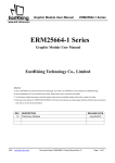
3.4. Power supplies and contrast control
The SGI01 requires a single +5V power supply. Its current consumption
without backlight and -VEE load is less than 50 mA. The SGI01 card has a
negative voltage generator on-board which can provide the -VEE for the
LCD. The value of the -VEE is trimmer settable between -5V and -20V. The
total load of the inverter must not exceed 400 mW. If this is not enough it is
possible to use external supply.
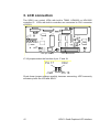
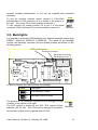
The following picture shows the location of the -VEE inverter, the contrast
and the -VEE trimmer, and the related jumpers and connectors.
P o w e r s u pp ly c o nn e ctor
N e g a tiv e vo lta g e g en e ra to r
Ve e ju m p e r
In te rna l co ntra st
-Ve e co ntro l
E x tern a l c o ntra s t co n n e cto r
The pinout of the power connector is the following:
No Nam
e
1 -VEE
2 VO
3 +5V
4 GND
Description
LCD power supply
Operating (contrast) voltage
Logic power supply for SGI01 and LCD
Ground
To use the internal -VEE supply leave J1 jumper connected and set the
proper -VEE voltage using P1 potentiometer. You can measure the -VEE on
the power connector (CN4) between pins 1 and 4. Always check -VEE
before connecting the LCD because incorrect -VEE may damage the LCD!
To use external -VEE supply remove J1 jumper, and connect the external
-VEE to CN4 power connector.
There are three ways of controlling the contrast (operating) voltage of the
LCD. There is a trimmer on the SGI01 card, it is possible to connect an
14
SGI01 Small Graphics LCD Interface
external contrast potentiometer or VO can be supplied and controlled
externally.
CN2
To use an external contrast control connect a 10k-20k
potentiometer to CN2 connector as it is shown in the picture on
the right. Then leave P2 in center position or remove it.
To use external VO control connect VO to pin 2 of the power
connector (CN4) and leave P2 in center position or remove it.
Potmeter
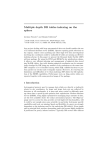
3.5. Backlights
It is possible to use either LED backlight or an optional backlight inverter type
DAS5V7, DAS5V10, DAS5V13 or DAS5V14. The place for the backlight
inverter, the backlight connector and the related jumpers are shown on the
following picture:
L E D curre n t lim iter
B ack lig h t ju m p e rs
B a cklig h t co n ne ctor
B a cklig h t in v e rte r
J2 and J3 jumpers are used to select the backlight.
Jumper
Description
J3
J2
LED backlight is used
J3
J2
Backlight inverter is used
The polarity of CN5 backlight connector if LED backlight is used
+
CN5
is shown in the picture to the right.
The LED current is limited by the R10, R18 current limiting
Backlight
resistors (2x4.7 1W). R10, R18 can be changed if necessary,
but the sum of them must be greater then 6 2W.
User's Manual Version 2.4 February 20, 1998
15
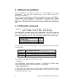
4. Software description
The commands of the SGI01 consist of a letter followed by various
parameters. The very first command sent to the SGI01 must be a
DefineLCD command.
There are a set of examples in the following sections to help use the SGI01.
The encoding of the examples is the following: The codes are in double
quotes ("") separated by space ( ) characters. A single letter denotes its
ASCII code, two consecutive hexadecimal number denotes the hexadecimal
code.
4.1. DefineLCD command
Syntax: A (LCD type) (LCD subtype) (size X low)
(size X high) (size Y low) (size Y high)
The DefineLCD command defines the configuration of the SGI01 card and
the connected LCD. The command sequence is seven bytes long. The first
byte is the command code "A". The second byte defines the controller type:
Controller type
External T6363
External HD61830
External HD61202
Code
1
2
3
The third byte defines the LCD subtype. The meaning depends on the LCD
controller type:
Controller
T6963
HD61830
HD61202
LCD subtype description
D7=1/0, Dual/single screen; D6-D0=Character width
D7=1/0, Dual/single screen; D6-D0=Character width
Not used
The last four bytes define the LCD X and Y size.
Example 1:
The configuration code sequence required for initializing a 240x64 single
screen LCD with external T6963 controller is the following:
"A 01 06 F0 00 40 00"
In which "A" is the command code, "00" means the optional T6963 controller
on the SGI01 card, "06" is the character width, "F0 00"=240 is the X size,
and "40 00"=64 is the Y size.
16
SGI01 Small Graphics LCD Interface
Example 2:
The configuration code sequence required for initializing a 128x64 single
screen LCD with on-board HD61202 is the following:
"A 03 08 80 00 40 00"
In which "A" is the command code, "03" means the LCD with on-board
HD61202 controller, "08" is no used, "80 00"=128 is the X size, and
"40 00"=64 is the Y size.
Example 3:
The configuration code sequence required for initializing a 240x64 dual
screen LCD with on-board HD61830 is the following:
"A 02 18 F0 00 40 00"
In which "A" is the command code, "03" means the LCD with on-board
HD61202 controller, "18" is the character width and the dual screen code,
"F0 00"=240 is the X size, and "40 00"=64 is the Y size. If possible program
character with to 8 pixels, because it is faster and use the memory more
efficiently.
4.2. SetMode command
Syntax: B (mode)
This command determines how the new pixel value replaces the old one.
The new value can overwrite the old one (COPY mode) or the result can be
the XOR, OR or AND relation of the old pixel and the new one. SetMode
affects all the other commands including FillScreen. The command is two
bytes long. The first byte is the command code "B" and the second byte is
the mode:
Code
0
1
2
3
Description
COPY mode: The new value overwrites the old one.
mode: The new pixel will be the AND
combination of the old one and the new one
OR mode: The new pixel will be the OR combination
of the old one and the new one
XOR mode: The new pixel will be the xOR
combination of the old one and the new one
AND
The use of the SetMode command is best illustrated in the examples of the
FillScreen command.
User's Manual Version 2.4 February 20, 1998
17
4.3. SetColor command
Syntax: C (color)
SetColor command defines the drawing color for all the other instructions.
The command is two bytes long. The command code "C" is followed by the
color code:
Code
0
1
Color description
Background color (Light gray on transflective LCDs)
Foreground color (Dark gray on transflective LCDs)
The use of the SetColor command is best illustrated in the examples of the
FillScreen command.
4.4. MoveTo command
Syntax: D (X low) (X high) (Y low) (Y high)
MoveTo is the most frequently used command. It sets the cursor position.
The command is five bytes long. The command code is "D" followed by the
X and the Y coordinates in the following order: (X low) (X high) (Y low) (Y
high). The coordinates of the top left corner of the LCD screen are (0,0).
Example 4:
The following code sequence moves the cursor to home position:
"D 00 00 00 00"
where "D" is the command code, "00 00"=0 is the X, and "00 00"=0 is the Y
coordinate.
4.5. MoveRel command
Syntax: Y (X low) (X high) (Y low) (Y high)
MoveRel is similar to MoveTo but the new cursor position is relative to the
current one. The command code is "Y" followed by the relative X and the Y
coordinates in the following order: (X low) (X high) (Y low) (Y high).
Example 5:
The following code sequence moves the cursor in X direction by 5 pixels:
"Y 05 00 00 00"
where "Y" is the command code, "05 00"=0 is the relative X, and "00 00"=0 is
the relative Y coordinate.
18
SGI01 Small Graphics LCD Interface
4.6. SetBacklight command
Syntax: E (on/off)
SetBacklight command is used for switching on or off the backlight. The
command is two bytes long. The command code is "E". followed by a
parameter byte which is 1 for switching on, and 0 for switching off the
backlight.
Example 6:
The following command is used for switching on the backlight:
"E 01"
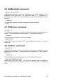
4.7. FillScreen command
Syntax: F
The FillScreen command is used for clearing, setting and inverting the entire
screen. This command has no parameters. The command code is "F".
Example 7:
The following code sequence inverts the screen:
"B 03 C 01 F"
where "B 03" sets XOR mode, "C 01" sets foreground color and "F" inverts
the screen.
4.8. PutPixel command
Syntax: G
PutPixel sets, resets or inverts one point on the screen, depending on the
mode and color settings. The command has no parameters. The command
code is "G".
Example 8:
The following code sequence sets point (5,10) on the LCD screen:
"B 00 C 01 D 05 00 0A 00 G"
where "B 00" sets COPY mode, "C 01" sets the drawing color to foreground
color, "D 05 00 0A 00" moves the cursor to (5,10) point and "G" sets the
pixel.
User's Manual Version 2.4 February 20, 1998
19
4.9. GetPixel command
Syntax: H
Using GetPixel command is a simple way of reading back the data displayed
on the LCD. The command has no parameters. The command code is "H".
The SGI01 returns the value of the pixel under the cursor (1 for foreground, 0
for background color).
Example 9:
The following code sequence reads back the value of (10,13):
"D 0A 00 0D 00 H"
4.10. LineTo command
Syntax: I (X low) (X high) (Y low) (Y high)
Draws a line from the current cursor position to (X,Y) and moves the cursor
to (X,Y) excluding the starting point. The command is five bytes long. The
command code "I" is followed by the new X and Y coordinates: I (X low) (X
high) (Y low) (Y high).
Example 10:
The following code sequence draws the two diagonals of a 240x64 LCD:
"D 00 00 00 00 G I EF 00 3F 00 D 00 00 3F 00 G I EF 00 00 00"
where "D 00 00 00 00" moves the cursor to (0,0) point, "I EF 00 3F 00"
draws a line to (239,63), "D 00 00 3F 00" moves the cursor to (0,63) and
"I EF 00 00 00" draws a line to (239,0). The color and the mode settings
affect the result.
4.11. LineRel command
Syntax: Z (X low) (X high) (Y low) (Y high)
LineRel is similar to LineTo but the line end position is relative to the cursor
position. The command code is "Z" followed by the relative X and the Y
coordinates in the following order: (X low) (X high) (Y low) (Y high).
The command is five bytes long. The command code "Z" is followed by the
new relative X and Y coordinates.
20
SGI01 Small Graphics LCD Interface
Example 11:
The following code sequence draws a triangle:
"D 00 00 00 00 Z 00 00 20 00 Z 20 00 E0 FF Z E0 FF 00 00"
where "D 00 00 00 00" moves the cursor to (0,0) point, "Z 00 00 20 00"
draws a line to (0,32), "Z 20 00 E0 FF" draws a line to (32,0) and
"Z E0 FF 00 00" draws a line to (32,0). The color and the mode settings
affect the result.
4.12. Rectangle command
Syntax: J (X low) (X high) (Y low) (Y high)
Rectangle command draws the outline of a rectangle. The top left corner of
the rectangle is the cursor position, the coordinates of the bottom right
corners is (X,Y) is defined in the command. After drawing the rectangle the
cursor is moved to the bottom right corner. The command if five bytes long.
The command code "J" is followed by the new X and Y coordinates: J (X low)
(X high) (Y low) (Y high).
Example 12:
The following code sequence draws a double lined frame to the 240x64
LCD:
"D 00 00 00 00 J EF 00 3F 00 D 02 00 02 00 J ED 00 3D 00"
where "D 00 00 00 00" moves the cursor position to (0,0), "J EF 00 3F 00"
draws the outer rectangle, "D 02 00 02 00" moves the cursor to (2,2) and
"J ED 00 3D 00" draws the inner rectangle. Note that the actual result
depends on the color and mode settings.
4.13. FillRectangle command
Syntax: K (X low) (X high) (Y low) (Y high)
FillRectangle command is similar to Rectangle command but it fills the inside
of the rectangle with the current drawing color. This command is also five
bytes long. The command code "K" is followed by the new X and Y
coordinates: K (X low) (X high) (Y low) (Y high).
Example 13:
The following code sequence inverts the area inside of the (0,2) (10,10)
rectangle:
"B 03 C 01 D 00 00 02 00 K 0A 00 0A 00"
where "B 03" sets XOR mode, "C 01" sets foreground color, "D 00 00 02 00"
moves the cursor position to (0,2) and "K 0A 00 0A 00" inverts the rectangle.
User's Manual Version 2.4 February 20, 1998
21
4.14. Circle command
Syntax: L (Radius low) (Radius high)
Circle command draws a circle on the screen. The center is the current
cursor position, the radius is the parameter of the command. The radius, like
everything on screen, is measured in pixels. The cursor position remains
unchanged. The command is three bytes long. The command code "L" is
followed by the radius: L (Radius low) (Radius high).
Example 14:
The following code sequence draws a small circle at the center of the
240x64 LCD screen:
"D 78 00 20 00 L 0A 00"
where "D 78 00 20 00" moves the cursor to the center of the screen and
"L 0A 00" draws a small circle. Note that the actual result depends on the
color and mode settings.
4.15. FillCircle command
Syntax: M (Radius low) (Radius high)
FillCircle command is similar to Circle command but it fills the circle. This
command is also three bytes long: The command code "M" is followed by the
radius: M (Radius low) (Radius high).
Example 15:
The following code sequence draws a small filled circle at the center of the
240x64 LCD screen:
"D 78 00 20 00 M 0A 00"
where "D 78 00 20 00" moves the cursor to the center of the screen and
"M 0A 00" draws a small filled circle. Note that the actual result depends on
the color and mode settings.
22
SGI01 Small Graphics LCD Interface
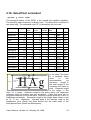
4.16. SelectFont command
Syntax: Q (font code)
The strongest feature of the SGI01 is the superb text handling capability.
The following table shows the available fonts. The SelectFont command is
two bytes long. The command code "Q" is followed by the font code.
Font name
Height
Character Ascender Descend
height
height
er height
Average
width
Example Code
Small 6x8
Small 8x8
Serif
Serif
Serif
Serif
Serif
8
8
10
11
13
16
20
7
7
6
7
9
10
13
0
0
2
2
2
3
3
1
1
2
2
2
3
4
6
8
4
5
5
7
8
Text
Text
Sans Serif
Sans Serif
Sans Serif
Sans Serif
Sans Serif
10
11
13
16
20
6
7
9
10
13
2
2
2
3
3
2
2
2
3
4
4
5
5
7
8
TEXT
Monospace
Monospace
Monospace
Monospace
10
11
13
16
6
7
9
10
2
2
2
3
2
2
2
3
4
5
5
7
"00"
"01"
TEXT
"10"
TEXT "11"
TEXT "12"
TEXT "13"
TEXT "14"
"20"
TEXT "21"
TEXT "22"
TEXT "23"
TEXT "24"
TEXT
"30"
TEXT "31"
TEXT "32"
TEXT "33"
In the table Font name
is a symbolic name
used
in
this
documentation
for
C ha rac te r
H e ig ht
h e ig ht
Height is
reference.
the total height of the
character font matrix in
D e s ce nd er
h eigh t
pixel. Character height
is the height of the
letter "H" in pixels. Ascender height is the place above the uppercase
character used for accents and row separation. (Note that there are no
accented characters in the code table. Accents could be drawn by LineTo or
PutBitmap commands). Descender height is the height below letters, used
by "g", "y" etc. characters. Average width is the average width of the
proportional fonts (Serifs and Sans Serifs) and the exact width of the
monospaced fonts (Small and Monospace).
As cen de r
h eigh t
HÁg
User's Manual Version 2.4 February 20, 1998
23
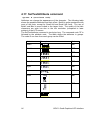
4.17. SetTextAttribute command
Syntax: R (attribute code)
Attributes can change the appearance of the character. The following table
shows the possible attributes and their effect. BoldX is quite spectacular with
most of the fonts, except for Small 6x8 and Small 8x8 fonts. The use of
BoldY and Bold is more limited to the larger fonts. The quality of the italic
characters are quite low due to the low resolution (compared to laser
printers) of the LCD screen.
The SetTextAttribute command is two bytes long. The command code "R" is
followed by the attribute code. The table shows the attributes in groups.
The code of one item from each group can be ORed.
Attribute name
BoldX
Example
BoldY
Italic
Underline
Right
Left
"40"
Text
Text
Text
Text
Text
Bold
Down
Mirror
24
"60"
"10"
"08"
"00"
"01"
"02"
Text
Up
Code
"20"
"03"
"04"
SGI01 Small Graphics LCD Interface
4.18. PutChar command
Syntax: S (character code)
PutChar is the simpler of the two character writing commands. It can display
only one character using the specified font and attributes. The command is
two bytes long. The character code "S" is followed by the character code.
The valid character codes are in Appendix B. The cursor position is the top
left corner of the character. After writing the character the cursor moves left
by the character width. Write mode and color settings affect the resulting
image in the usual way.
Example 16:
The following code sequence writes a large bold underlined Serif "A" to the
top left corner of the LCD:
"D 00 00 00 00 B 01 C 01 Q 14 R 68 S A"
where "D 00 00 00 00" moves the cursor to the top left corner of the screen,
"B 01 C 01" sets OR mode and selects foreground color, "Q 14" selects the
largest Serif font, "R 68" sets bold and underline, and "S A" writes the
character.
4.19. PutText command
Syntax: T <string> (00)
PutText is the more widely used character writing command. It can write any
number of characters, possibly in multiple lines. This is a variable length
command. The command code "T" is followed by the character string. The
string can contain any number of valid ASCII characters (see Appendix B),
"0D" codes for carriage return and "0A" for line feed. The string and the
command is terminated by "00".
Example 17:
The following code sequence writes the text "Trixel" upside down to the LCD
using 16 pixel high Sans Serif with BoldX attribute:
"D 64 00 20 00 B 01 C 01 Q 23 R 21 T T r i x e l 00"
where "D 64 00 20 00" moves the cursor to (100,32) point, "B 01 C 01" sets
OR mode and selects foreground color, "Q 23" selects the 16 pixel high Sans
Serif font, "R 68" sets BoldX and orientation, and "T T r i x e l" writes the
string and "00" terminates the string.
User's Manual Version 2.4 February 20, 1998
25
4.20. GetStringWidth command
Syntax: U <string> (00)
GetStringWidth command is used in conjunction with proportional spaced
character fonts and PutText command. It returns the overall width of a
character string. The format of the command is similar to PutText command.
The command code "U" is followed by a "00" terminated string. The SGI01
returns the with of the string in pixel in two bytes (low byte first). Note that
the string width varies with the selected font and attributes.
Example 18:
The following code sequence determines the width of the string "Trixel":
"U T r i x e l 00"
The returned value can be used to justify the string properly.
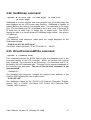
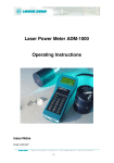
4.21. PutBitmap command
Syntax: V (X size low) (X size hi) (Y size low)
(Y size hi) <image>
Complex images such as symbols and logos are most easily displayed by
the PutBitmap command.
0.6 0.5 0.4 0.3 0.2 0.1 0.0 1.7 1.6 1.5 1.4
PutBitmap is a variable length command. 0.7
2.7 2.6 2.5 2.4 2.3 2.2 2.1 2.0 3.7 3.6 3.5 3.4
The command code "V" is followed by the 4.7 4.6 4.5 4.4 4.3 4.2 4.1 4.0 5.7 5.6 5.5 5.4
6.6 6.5 6.4 6.3 6.2 6.1 6.0 7.7 7.6 7.5 7.4
X and the Y size of the bitmap then the 6.7
8.7 8.6 8.5 8.4 8.3 8.2 8.1 8.0 9.7 9.6 9.5 9.4
image bytes: V (X size low) (X size high) 10.7 10.6 10.5 10.4 10.3 10.2 10.1 10.0 11.7 11.6 11.5 11.4
12.6 12.5 12.4 12.3 12.2 12.1 12.0 13.7 13.6 13.5 13.4
(Y size low) (Y size high) image bytes. The 12.7
14.7 14.6 14.5 14.4 14.3 14.2 14.1 14.0 15.7 15.6 15.5 15.4
coding is shown on the picture. The first 16.7 16.6 16.5 16.4 16.3 16.2 16.1 16.0 17.7 17.6 17.5 17.4
18.6 18.5 18.4 18.3 18.2 18.1 18.0 19.7 19.6 19.5 19.4
digit is the byte number, and the second 18.7
20.7 20.6 20.5 20.4 20.3 20.2 20.1 20.0 21.7 21.6 21.5 21.4
22.7 22.6 22.5 22.4 22.3 22.2 22.1 22.0 23.7 23.6 23.5 23.4
digit is the bit number.
24.7 24.6 24.5 24.4 24.3 24.2 24.1 24.0 25.7 25.6 25.5 25.4
Example 19:
The following code sequence draws the image in the picture
"D 00 00 00 00 V 0C 00 0D 00 7F 80 7F 80 60 C0 ... 60 60"
where "D 00 00 00 00" moves the cursor to the top left corner of the screen,
"V 0C 00 0D 00" defines the 12x13 image, and the following bytes define the
image. In this example the PutBitmap command is 1+2+2+13*(12/8+1)=31
bytes long.
26
SGI01 Small Graphics LCD Interface
4.22. GetBitmap command
Syntax: W (X size low) (X size high) (Y size low)
(Y size high)
GetBitmap is a more complex and more powerful way of reading back the
data displayed on the LCD screen than GetPixel. GetBitmap is capable of
reading back all the data of a rectangular area. The command is five bytes
long. The command code "W" is followed by the X and Y size of the area: W
(X width low) (X width high) (Y height low) (Y height high). The SGI01
returns the data in a format similar to PutBitmap image format. See picture
in PutBitmap.
Example 20:
The following code sequence reads back the image displayed by the
PutBitmap example:
"D 00 00 00 00 V 0C 00 0D 00 H"
The SGI01 returns 26 bytes ("7F 80 7F 80 60 C0 ... 60 60").
4.23. DirectCommandWrite command
Syntax: a (command code)
This command instructs the SGI01 card to write the parameter byte to the
command register of the LCD controller. SGI01 will perform the required
busy checking. The command is two bytes long. The command code is "a"
followed by the LCD command byte. The effect of the command depends on
the controller type and mode. The use of this low level command is not
recommended.
Example 21:
The following code sequence changes the graphic home address of the
T6963 to 500H allowing the use of split screen:
"b 00 b 05 a 42"
See Application Notes for the T6963C LCD Graphics Controller, Toshiba,
August, 1991 or T6963C (Dot Matrix LCD Control LSI) Technical Data,
Toshiba, 1991 for details.
User's Manual Version 2.4 February 20, 1998
27
4.24. DirectDataWrite command
Syntax: b (data byte)
This command instructs the SGI01 card to write the parameter byte to the
data register of the LCD controller. SGI01 will perform the required busy
checking. The command is two bytes long. The command code is "b"
followed by the LCD data byte. The effect of the command depends on the
controller type and mode. The use of this low level command is not
recommended.
4.25. DirectStatusRead command
Syntax: c
This command instructs the SGI01 card to read the status/command register
of the LCD controller. SGI01 will perform the required busy checking. The
read byte is available in the output FIFO of the SGI01. The command has
no parameters. The command code is "c". The effect of this command
depends on the controller type and mode. The use of this low level
command is not recommended.
4.26. DirectDataRead command
Syntax: d
This command instructs the SGI01 card to read the data register of the LCD
controller. SGI01 will perform the required busy checking. The read byte is
available in the output FIFO of the SGI01. The command has no
parameters. The command code is "d". The effect of this command
depends on the controller type and mode. The use of this low level
command is not recommended.
28
SGI01 Small Graphics LCD Interface
4.27. DirectChipselect command
Syntax: e (select code)
Some LCD with built-in HD61202 controller have two HD61202s on-board.
To select between the two controllers use the DirectChipselect command.
The command is two bytes long. The command code is "e". the select code
is the following:
Description
Select controller #1
Select controller #2
Select both controllers
Select code
"01"
"02"
"03"
The use of this low level command is not recommended.
4.28. Echo command
Syntax: x
This command is used for testing the connection of the SGI01. When the
SGI01 receives Echo command it returns the command code "x". The
command has no parameters.
User's Manual Version 2.4 February 20, 1998
29
5. Built-in demo
There is a built-in demo available for the most commonly used LCDs. To
select demo mode switch off SW1-8. The remaining DIP switches determine
the controller type and the LCD size. See Appendix C.
If your LCD size is not listed, try to set a similar size. If the controller type
and the single/dual switches are set correctly the demo probably works,
though it is not guarantied.
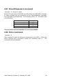
5.1. Demo keys
It is possible to connect two keys to the RS-232 interface of SGI01 which
work in demo mode as a PAUSE/CONTINUE and FAST FORWARD. The
demo is stopped while the PAUSE/CONTINUE button is pressed and
continue at normal speed when released. If the FAST FORWARD button is
pressed the demo is running at the fastest possible speed. It is useful for
finding a particular screen. The connection is the following:
D TR
F a st forw a rd
P ause /C o ntin ue
47 k
47 k
R xD
D SR
T xD
The demo will work without these keys connected, but the time between
pictures will be set to about one second.
6. Part numbering
There are two versions of SGI01:
SGI01A: 9-pin D type RS-232 connector
SGI01B: 2x5 pin RS-232 connector
30
SGI01 Small Graphics LCD Interface
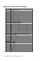
Appendix A: DIP switch settings
Dipswitch Description
1xxx xxx1 Serial line is used
0xxx xxx1 I²C interface is used
1000 0xx1
150 baud serial line
1001 0xx1
300 baud serial line
1010 0xx1
600 baud serial line
1011 0xx1
1200 baud serial line
1100 0xx1
2400 baud serial line
1101 0xx1
4800 baud serial line
1110 0xx1
19200 baud serial line
1111 0xx1
9600 baud serial line
1000 1xx1
38400 baud serial line
1001 1xx1
57600 baud serial line
1010 1xx1 115200 baud serial line
0000 xxx1 I²C write address 70H, read address 71H
0001 xxx1 I²C write address 72H, read address 73H
0010 xxx1 I²C write address 74H, read address 75H
0011 xxx1 I²C write address 76H, read address 77H
0100 xxx1 I²C write address 78H, read address 79H
0101 xxx1 I²C write address 7AH, read address 7BH
0110 xxx1 I²C write address 7CH, read address 7DH
0111 xxx1 I²C write address 7EH, read address 7FH
xxxx xx11 Switch Vee on/off
xxxx xx01 Do not switch Vee (Use for setting Vee only)
xxxx xxx0 Demo mode
xxxx x010 External T6963
xxxx x100 External HD61830
xxxx x110 External HD61202
xxxx 0xx0 Single screen
xxxx 1xx0 Dual screen
0000 xxx0
32x120
0001 xxx0
32x128
0010 xxx0
64x120
0011 xxx0
64x128
0100 xxx0
64x240
0101 xxx0
64x256
1000 xxx0
128x120
1001 xxx0
128x128
1010 xxx0
128x240
1011 xxx0
128x256
In the table 0=on, 1=off, x=irrelevant or defined elsewhere
User's Manual Version 2.4 February 20, 1998
31
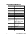
Appendix B: Command summary
Command name
DefineLCD
SetMode
SetColor
MoveTo
SetBacklight
FillScreen
PutPixel
GetPixel
LineTo
Rectangle
FillRectangle
Circle
FillCircle
SelectFont
SetTextAttribute
PutChar
PutText
GetStringWidth
PutBitmap
GetBitmap
MoveRel
LineRel
DirectCommandWrite
DirectDataWrite
DirectStatusRead
DirectDataRead
DirectChipselect
Echo
32
Command code
A (LCD type) (LCD subtype)
(size X low) (size X high)
(size Y low) (size Y high)
B (mode)
C (color)
D (X low) (X high) (Y low) (Y high)
E (on/off)
F
G
H
I (X low) (X high) (Y low) (Y high)
J (X low) (X high) (Y low) (Y high)
K (X low) (X high) (Y low) (Y high)
L (Radius low) (Radius high)
M (Radius low) (Radius high)
Q (font code)
R (attribute code)
S (character)
T <string> (00)
U <string> (00)
V (X size low) (X size high)
(Y size low) (Y size high) <image>
W (X size low) (X size high)
(Y size low) (Y size high)
Y (X low) (X high)
(Y low) (Y high)
Z (X low) (X high)
(Y low) (Y high)
a (command)
b (data)
c
d
e (select code)
x
SGI01 Small Graphics LCD Interface