1
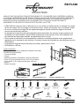
EM-PLAB2
INSTRUCTIONS
PLEASE READ THESE INSTRUCTIONS CAREFULLY AND KEEP FOR FUTURE REFERENCE! IF
YOU DO NOT UNDERSTAND THE INSTRUCTIONS, OR DO NOT FEEL THAT YOU CAN FOLLOW
THEM SAFELY, CONTACT A QUALIFIED CONTRACTOR. THE WARRANTY WILL BE HONOURED IF
ACCOMPANIED BY AN ORIGINAL SALES RECEIPT, AND ONLY IF THE INSTRUCTIONS HAVE
BEEN FOLLOWED EXACTLY.
• The EM-PLAB2 is designed to mount a panel onto a vertical wall. Hardware for mounting to a wood stud
is included. For mounting to any other surface, it is recommended you contact a qualified contractor.
• The wall or mounting surface must be capable of supporting the combined weight of the mount and the
display, otherwise the structure must be reinforced.
• Safety gear and proper tools must be used. A minimum of two people are required for this installation.
Failure to use safety gear and/or attempting this installation alone can result in property damage,
serious injury, or death.
• Follow all instructions and recommendations regarding adequate ventilation and suitable locations for
mounting your flat panel. Consult the owner‘s manual for your flat panel for more information.
• This product will hold flat panels up to 60” and weighing up to 150 lbs.
• VESA 600mm x 400mm
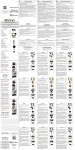
Tools Required
• Stud finder ("edge to edge" stud finder is recommended)
• Phillips screwdriver
• Pencil
• Hammer Drill (Concrete installation only)
• 1/4" drill bit for wood studs, 3/8” drill bit for concrete
• 7/16" socket wrench or bit driver for wood screws
• Level
• Tape measure
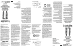
Parts List
C
B
A
M4*12mm
(x4)
M4*30mm
(x4)
M6*30mm
(x4)
Adaptor Brackets (x2)
Adaptor Plate (x1)
Wall Plate (x1)
D
M8*16mm
(x4)
E
F
M8*30mm
(x4)
G
Metal Washer
Ø6mm (x8)
H
Metal Washer
Ø8mm (x4)
M6*12mm
(x8)
M
J
I
K
M8*15mm
(x4)
1
N
L
Slider Plates
(x4)
Allen Key (x1)
Spacers (x4)
Anchor (x4)
Lag Bolt
8*70mm (x4)
EM-PLAB2.HB.092012.IM
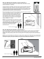
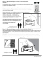
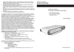
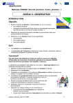
Step 1A - Mounting the wall plate to wooden studs (Fig. 1)
The EM-PLAB2 can be mounted onto two wooden studs, with center to center
distances between 16" (406mm).
Using an electronic stud finder, locate the center of the two wooden studs at the
desired mounting location. Mark the stud center positions directly on the wall.
Connect the stud marks with a horizontal line and find the center between them
to represent where you wish the center of the screen to be located. Be sure to
measure and mark the center of this horizontal line.
Place the wall plate on the wall. Pin the wall plate to the center mark on the wall.
Using a level (bubble or laser ), level the guide, and
then press the adhesive backing against the wall to
hold the guide in place. Using a 1/4" (6mm) drill bit,
drill 4 pilot holes into the center of the studs (through
6mm (1/4”)
Hole
the mounting hole cut-out sections of the template),
Lag Bolt
down to a depth of 3" (76mm).
8*70mm
Fig. 1
Wood Stud
NOTE: It is not recommended to use a drill driver or impact
wrench to tighten bolts. Tighten lag bolts so that wall plate
is firmly attached to wall, but DO NOT over-tighten. The lag
bolts can be damaged by over-tightening which will strip
their threading. Final tightening of lag bolts
should be done by hand using a ratchet
wrench and socket.
CAUTION: Two people recommended
for lifting
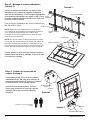
Step 1B - Mounting the wall plate to concrete (Fig. 2)
Place the wall plate on the wall. Pin the wall plate to the center mark on the wall. Using a level (bubble or
laser), level the guide, and then press the adhesive backing against the wall to hold the guide in place.
Using a 3/8" (10mm) masonry drill bit, drill 4 mounting holes 3-1/8" (80mm) deep into the concrete/masonry
surface.
NOTE: It is not recommended to use a drill driver or impact wrench to tighten bolts. Tighten lag bolts so that wall plate is
firmly attached to wall, but DO NOT over-tighten. The lag bolts can be damaged by over-tightening which will strip their
threading. Final tightening of lag bolts should be done by hand using a ratchet wrench and socket.
Fig. 2
10mm (3/8”)
Hole
Lag Bolt
8*70mm
Wall Anchor
CAUTION: Two people recommended
for lifting
2
EM-PLAB2.HB.092012.IM
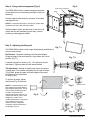
Fig. 3
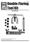
Step 2 - Assembling the Adaptor Plate (Fig.3)
Insert slider plates (x4) into the adaptor rails, then
insert the adaptor brackets into the adaptor rails.
Attach the adaptor bracket and slider plates with four
M6*12mm screws and four Ø6mm metal washers
using a Phillips screw driver.
Attach the adaptor bracket onto the panel using
the provided M4, M6, M8 screws.
Adaptor rail
Adaptor bracket
Slider plate
M6*12mm
screw
NOTE: Determine the correct diameter of screw to use by
checking your panel’s user manual, or by testing the
screws provided. Make sure not to force any of the screws
into the panel.
Ø6mm metal
washers
Mounting screws
NOTE: If the back of your panel is flat and the mounting
holes are flush with the surface, use the shorter panel
screws. If the back of your panel is curved, protruded, or
recessed, use the longer screws. You may also need to
use spacers with the longer screws.
Adaptor brackets
Ø6mm metal
washers
Now slide the opposite mounting rail into position,
align it with the mounting holes, and secure using the
mounting hardware.
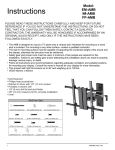
Step 3 - Attaching the flat panel to the
mount
By hand, insert two M8*15mm screws and Ø8mm
metal washers into threaded holes on the adaptor
panel as shown in Fig.4. Leave approximately 3/8”
of exposed thread.
With the help of an assistant, carefully lift the
panel and attach it to the mount head cautiously.
Tighten the screws as shown in Fig.5.
Ø8mm metal
washer
M8*15mm
screw
Fig. 4
CAUTION: Two people recommended
for lifting
Fig. 5
M8*15mm
screw
Ø8mm metal
washer
3
EM-PLAB2.HB.092012.IM
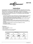
Step 4 - Using cable management (Fig. 6)
The EM-PLAB2 includes a cable management system
where cable can be routed along the length of the arm
assembly.
U-Cap cable management
Fig. 6
Cable
Route the panel cable along the entrance of the cable
management slot.
NOTE: For optimal performance, route the AC power cable
separately from the audio and video cables
With all cables in place, pull the panel in and out to be
certain that the arm assembly moves freely, without
stretching or damaging the cables.
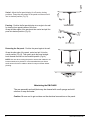
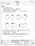
Step 5 - Adjusting the flat panel
The EM-PLAB2 provides a wide range of adjustment possibilities to
suit your environment.
Fig. 7.1
Roll Control - Horizontal levelling of the flat panel display.
Grasp the edge of the panel and roll it up or down into a level
position (Fig.7.1).
Fig. 7.2
Loosen the screws as shown in Fig. 7.2 to allow roll control
adjustment. Tighten screws by hand when finished.
Tilt Adjustment - Raising or lowering the screen to improve
viewing angle. First release completely the tilt knob as shown
(Fig.9) Next, grasp the upper and lower edges of the panel,
and then turn it to the desired
tilt angle (Fig.8).
To lock the tilt angle, tighten
the tilt knob (Fig.10) securely.
NOTE: For heavier panels, never
fully release the tilt knob without
fully supporting the panel. The tilt
lever includes a ratchet function,
so that it can be lifted and
repositioned for the next turn. To
operate the ratchet, pull the lever
straight out, rotate it to an
unobstructed position, release the
lever, and then turn it in the
desired direction. Repeat as
necessary until the tilt tension is
set properly (Fig.10)
Release tilt knob
Fig. 8
a
Turn
4
Fig. 9
Tilt knob
c
b
Fig. 10
d
Tighten
EM-PLAB2.HB.092012.IM
Swivel- Adjust the flat panel display for off-center viewing
positions. Grasp the side edges of the panel and then swivel it
into its desired position (Fig.11).
Fig. 11
Panning - Position the flat panel display at an angle to the wall
for viewing from opposite sides of the room.
Grasp the side edges of the panel and then swivel and pull the
panel into desired position (Fig.12).
Fig. 12
Retracting the flat panel - Position the panel against the wall.
Grasp the side edge of the panel, swivel and pull it into the
center position (Fig.13). Then gently push the panel straight
back towards the wall into the retracted position (Fig.14).
NOTE: Use care when moving the panel to ensure that cables do not
become stretched or pinched. It is recommended that you allow a
small amount of slack in cables to allow for easy movement without
pinching.
Fig. 13
Fig. 14
Maintaining the EM-PLAB2
The arm assembly and wall plate may be cleaned with a soft sponge and mild
solution of soap and water.
Caution: Be sure not to get moisture on the electrical connections or the panel.
5
EM-PLAB2.HB.092012.IM
EM-PLAB2
INSTRUCTIONS
VEUILLEZ LIRE CES INSTRUCTIONS ATTENTIVEMENT ET LES GARDER POUR Y RÉFÉRER AU BESOIN.
SI VOUS NE COMPRENEZ PAS LES INSTRUCTIONS OU SI VOUS NE CROYEZ PAS ÊTRE EN MESURE DE
LES SUIVRE EN TOUTE SÉCURI-TÉ, VEUILLEZ COMMUNIQUER AVEC UN TECHNICIEN QUALIFIÉ. LA
GARANTIE NE SERA HONORÉE QU'EN LA PRÉSENCE DU COUPON DE CAISSE ORIGINAL ET
UNIQUEMENT SI LES INSTRUCTIONS ONT ÉTÉ SUIVIES À LA LETTRE.
• L'EM-PLAB2 est conçu pour fixer un téléviseur sur un mur vertical. Le matériel servant au montage sur montant
de bois est compris. Pour le montage sur toute autre surface, veuillez communiquer avec un technicien qualifié.
• Le mur ou la surface de montage doit être capable de supporter le poids combiné du support et de l'écran,
•
•
•
•
sinon la structure doit être renforcée.
Un équipement de sécurité et des outils appropriés doivent être utilisés. Un minimum de deux personnes est
nécessaire pour cette installation. Ne pas utiliser d'équipement de sécurité et/ou tenter cette installation seul
peut entraîner des dommages matériels, des blessures graves ou la mort.
Suivez toutes les instructions et recommandations concernant la ventilation adéquate et des emplacements
appropriés pour le montage de votre téléviseur. Consultez le manuel de l'utilisateur de votre téléviseur pour plus
d'informations.
Ce produit peut supporter des écrans plats jusqu’à 60 po, pesant jusqu'à 150 lb.
VESA 600 mm x 400 mm
Outils nécessaires
• Détecteur de montant (un appareil qui détecte le bord des
montants est recommandé)
• Tournevis Phillips
• Crayon
• Marteau perforateur (installation sur béton seulement)
• Foret 1/4" pour montants de bois, foret 3/8" pour béton
• Clé à douille 7/16" ou porte-embout pour vis à bois
• Niveau
Liste de pièces
• Ruban à mesurer
C
B
A
M4*12mm
(x4)
M4*30mm
(x4)
M6*30mm
(x4)
Supports d'adaptation (x2)
Plaque adaptatrice (x1)
Plaque murale (x1)
D
M8*16mm
(x4)
E
F
M8*30mm
(x4)
G
Rondelle métallique
Ø6mm (x8)
L
Rondelle métallique
M6*12mm
(x8)
Ø8mm (x4)
M
N
J
I
K
M8*15mm
(x4)
6
H
Plaques coulissantes
(x4)
Clé Allen (x1)
Cales (x4)
Cheville (x4)
Boulon
8*70mm (x4)
EM-PLAB2.HB.092012.IM
Étape 1A - Montage de la plaque murale aux montants de bois
(Schéma 1)
Le support EM-PLAB2 peut être monté sur deux montants de bois dont la distance d'un centre
à l'autre de ceux-ci est de 16" (406 mm).
À l'aide d'un détecteur de montants électronique, localisez le centre de deux montants de bois
à l'emplacement de montage désiré. Marquez le centre des montants directement sur le mur.
Reliez les marques avec une ligne horizontale et trouvez le centre entre ces marques, qui
représentera l'emplacement du centre de l'écran. Assurez-vous de mesurer et de marquer le
centre de cette ligne horizontale.
Placez la plaque murale sur le mur. Épinglez le guide sur la marque centrale au mur.
À l'aide d'un niveau (à bulle ou à laser), alignez le guide et
appuyez sur la bande adhésive contre le mur afin de
maintenir le guide en place. À l'aide d'un foret de
1/4" (6 mm), percez 4 trous de départ au centre des
Trou 6 mm
montants (à travers les ouvertures pour trous de montage
(1/4”)
du guide), jusqu'à une profondeur de 3" (76 mm).
Schéma 1
Clou de Bois
Boulon 8*70 mm
REMARQUE : l'utilisation d'une perceuse-visseuse ou d'une clé à
chocs n'est pas recommandée pour visser les boulons. Serrez les
boulons de sorte que la plaque murale soit fermement fixée au
mur, mais NE les serrez PAS trop fort. Cela pourrait endommager
les boulons et en abîmer le filetage. Le serrage final des boulons
devrait être fait à la main à l'aide d'une clé à
cliquet avec douille.
ATTENTION: Deux personnes sont
recommandées pour soulever le moniteur
Étape 1B - Montage de la plaque murale sur un mur de béton (Schéma 2)
Placez la plaque murale sur le mur. Épinglez le guide sur la marque centrale au mur. À l'aide d'un niveau (à bulle ou à
laser), alignez le guide et appuyez sur la bande adhésive contre le mur afin de maintenir le guide en place. À l'aide d'un
foret de maçonnerie de 3/8" (10 mm), percez 4 trous de montage d'une profondeur de 3 1/8" (80 mm) dans le mur de
béton/maçonnerie.
REMARQUE : l'utilisation d'une perceuse-visseuse ou d'une clé à chocs n'est pas recommandée pour visser les
boulons. Serrez les boulons de sorte que la plaque murale soit fermement fixée au mur, mais NE les serrez PAS trop
fort. Cela pourrait endommager les boulons et en abîmer le filetage. Le serrage final des boulons devrait être fait à la
main à l'aide d'une clé à cliquet avec douille.
Schéma 2
Trou 10 mm
(3/8”)
Cheville
Boulon 8*70 mm
ATTENTION: Deux personnes sont
recommandées pour soulever le moniteur
7
EM-PLAB2.HB.092012.IM
Étape 2 - Montage de la plaque adaptatrice
(Schéma 3)
Schéma 3
Insérer les plaques coulissantes (x4) dans les rails
adaptateurs, puis insérez les supports d'adaptation
dans les rails adaptateurs. Fixez le support d'adaptation
et les plaques coulissantes avec quatre vis M6*12 mm Plaques
et quatre rondelles métalliques de Ø6 mm à l'aide d'un coulissantes
tournevis à tête cruciforme.
Rail
Supports d'adaptation
Fixez le support d'adaptation sur l'écran à l'aide des vis
M4, M6 et M8 fournies.
Vis M6*12 mm
NOTE: Déterminez le bon diamètre de la vis à utiliser
en consultant la documentation accompagnant votre écran
ou en es sayant soigneusement une vis de chaque
dimension. Veillez à ne pas forcer les vis dans les ouver
tures de montage de l'écran.
Rondelle métallique
Ø6 mm
Vis de montage
NOTE: Si le dos de l'écran est plat et les trous de montage
sont au ras de la surface, utilisez les vis les plus courtes. Si
le dos de votre téléviseur est incurvé, protubérant ou con
cave, utilisez les vis les plus longues. Vous aurez peut-être
besoin des cales d’espacement avec les vis plus longues.
Supports d'adaptation
Rondelle métallique Ø6 mm
Ensuite, glissez le rail de montage opposé en position,
alignez-le avec les trous de montage et fixez-le à l'aide
du matériel de montage.
Étape 3 - Fixation de l'écran plats au
support (Schéma 4)
Insérez deux vis M8*15 mm et deux rondelles
métalliques Ø8 mm dans les trous filetés sur le
panneau adaptateur comme le montre le Schéma
4. Laissez environ 3/8"du filetage exposé.
Avec l'aide d'une autre personne, soulevez
l'écran avec précaution et fixez-le à la tête de
montage. Serrez les vis comme indiqué au
Schéma 5.
Rondelle métallique
Ø8 mm
Vis M8*15
mm
Schéma 4
CAUTION: Two people recommended
for lifting
Schéma 5
Vis M8*15
mm
Rondelle métallique Ø8 mm
8
EM-PLAB2.HB.092012.IM
Étape 4 - Passe-câble (Schéma 6)
Le support EM-PLAB2 propose un système de gestion du
câble grâce auquel le câble peut être dirigé le long du
bras.
Schéma 6
Passe-câble
Câble
Dirigez le câble de l'écran plat à travers le passe-câble.
REMARQUE : Pour des performances optimales, dirigez
le câble d'alimentation CA séparément des câbles audio
et vidéo.
Lorsque tous les câbles sont en place, avancez et
reculez l'écran plat afin de vous assurer que le bras
bouge librement, sans endommager ou tendre les
câbles.
Étape 5 - Ajustement de l'écran plat
Schéma 7.1
Le support EM-PLAB2 peut s'ajuster d'une multitude de façons pour
convenir à votre environnement.
Contrôle du niveau : Mise à niveau horizontale de l'écran plat. Saisissez les bords
latéraux de l'écran et faites-le pivoter vers le haut ou vers le bas jusqu'à ce qu'il soit au
niveau (Schéma 7.1).
Schéma 7.2
Desserrez les vis comme indiqué au Schéma 7.2 pour effectuer le
contrôle du niveau. Serrez les vis à la main lorsque vous avez
terminé.
Ajustement de l'inclinaison : Inclinaison vers le haut ou vers le
bas de l'écran pour améliorer l'angle de visualisation. Tout d'abord,
relâchez complètement le bouton d'inclinaison tel que montré
(Schéma 9). Ensuite, saisissez les bords supérieur et inférieur de
l'écran et inclinez-le selon la position désirée (Schéma 8).
Pour verrouiller la position, serrez
fermement le bouton d'inclinaison
(Schéma 15).
REMARQUE : Pour les écrans plus
lourds, ne déverrouillez jamais
complètement le bouton d'inclinaison
sans d'abord supporter entièrement
l'écran. Le levier d'inclinaison intègre
un cliquet, de sorte qu'il puisse être
soulevé et positionné de nouveau
lors de l'utilisation suivante. Pour
faire fonctionner le cliquet, tirez et
redressez complètement le levier,
faites-le pivoter dans une position
libre de tout obstacle, relâchez le
levier et tournez-le dans la direction
désirée. Répéter autant de fois que
nécessaire jusqu'à ce que la tension
d'inclinaison soit réglée
adéquatement (Schéma 10).
9
Schéma 9
Bouton
Relâchez le
bouton
d'inclinaison
Schéma 8
a
Tournez
c
b
Schéma 10 d
Serrez
EM-PLAB2.HB.092012.IM
Pivot : Ajustement de l'écran plat pour une position de
visualisation décentrée. Saisissez les bords latéraux de l'écran,
puis faites pivoter l'écran dans la position désirée (Schéma 11).
Schéma 11
Panoramique : Positionnement de l'écran plat selon un certain
angle avec le mur pour visualisation à partir d'endroits opposés
dans la pièce. Saisissez les bords latéraux de l'écran et
faites-le pivoter et tirez-le jusqu'à ce qu'il soit dans la position
désirée (Schéma 12).
Schéma 12
Rentrer l'écran plat : Positionnement de l'écran contre le mur.
Saisissez les bords latéraux de l'écran et faites-le pivoter et
tirez-le jusqu'à ce qu'il soit en position centrale (Schéma 13).
Puis, poussez-le délicatement vers l'arrière en direction du mur,
en position rentrée (Schéma 14).
REMARQUE : Prenez garde lors du déplacement de l'écran à ce que
les câbles ne soient pas tendus ou écrasés. Il est recommandé de
laisser un peu de jeu dans les câbles pour permettre un mouvement
aisé, sans pincement.
Schéma 13
Schéma 14
Entretien du EM-PLAB2
Le bras et la plaque murale peuvent être nettoyés à l'aide d'une éponge douce et d'une solution
d'eau et de savon diluée.
Mise en garde : Assurez-vous de ne pas mouiller les connexions électriques ou l'écran.
10
EM-PLAB2.HB.092012.IM