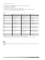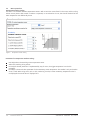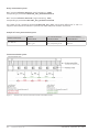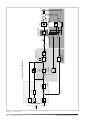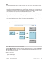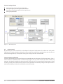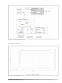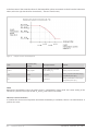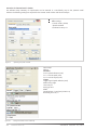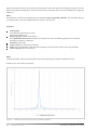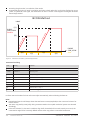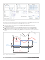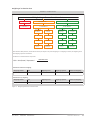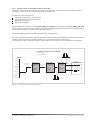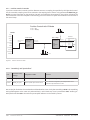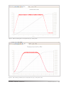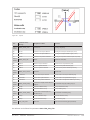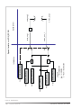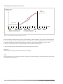
1
Application Manual AC Servo Controller YukonDrive Harmonic Drive AG 1003374 01/2012 Contens 1. Power stage...........................................................................................................................................................5 1.1 Setting the power stage parameters......................................................................................................................... 5 2. Motor......................................................................................................................................................................6 2.1 Loading motor data.......................................................................................................................................................... 7 2.1.1 Motor selection................................................................................................................................................................ 7 2.2 Data sets for third-party motors................................................................................................................................. 7 2.2.1 Determining the data set for a rotary synchronous machine..................................................................... 7 2.3 Linear motor......................................................................................................................................................................... 9 2.4 Asynchronous motor......................................................................................................................................................... 11 2.4.1 Electrical data.................................................................................................................................................................. 11 2.4.2 Saturation characteristic for main inductance................................................................................................. 13 2.5 Motor protection................................................................................................................................................................ 14 3. Encoder...................................................................................................................................................................19 3.1 SinCos X7 (channel 1)...................................................................................................................................................... 21 3.1.1 Zero pulse evaluation via encoder channel 1..................................................................................................... 24 3.1.2 Overflow shift in multiturn range............................................................................................................................ 24 3.1.3 Use of a multiturn encoder as a singleturn encoder....................................................................................... 25 3.1.4 Encoder correction (GPOC)......................................................................................................................................... 25 3.2 Resolver X6 (channel 2).................................................................................................................................................. 27 3.3 Optional encoder module X8 (channel 3)............................................................................................................... 28 3.4 Encoder gearing................................................................................................................................................................. 28 3.5 Increment-coded reference marks.............................................................................................................................. 29 3.6 Pin assignment for X6 and X7/X8............................................................................................................................. 31 4. Control....................................................................................................................................................................33 4.1 Control basic setting......................................................................................................................................................... 33 4.2 Current control.................................................................................................................................................................... 36 4.2.1 Detent torque compensation/Anti-cogging...................................................................................................... 38 4.2.2 Advanced torque control............................................................................................................................................ 40 4.2.3 Current control with defined bandwidth............................................................................................................. 43 4.3 Speed control....................................................................................................................................................................... 44 4.4 Position control................................................................................................................................................................... 55 4.5 Asynchronous motor field-weakening...................................................................................................................... 64 4.6 Synchronous motor field-weakening......................................................................................................................... 69 4.7 Autocommutation............................................................................................................................................................. 73 4.8 Commissioning.................................................................................................................................................................... 75 4.8.1 Autotuning........................................................................................................................................................................ 75 4.8.2 Test signal generator (TG).......................................................................................................................................... 76 4.9 Motor test via V/F characteristic................................................................................................................................ 80 4.10 Axis correction.................................................................................................................................................................. 81 5. Motion profile.........................................................................................................................................................85 5.1 Scaling................................................................................................................................................................................... 86 5.1.1 Standard/DS 402 Profile............................................................................................................................................ 86 5.1.2 “USER” scaling without scaling wizard................................................................................................................. 97 5.2 Basic setting......................................................................................................................................................................... 99 5.2.1 Control location, control source/Set control and Reference...................................................................... 101 5.2.2 Profiles............................................................................................................................................................................... 101 5.2.3 Profile Generator/Interpolated position mode................................................................................................ 101 5.2.4 Speed control via the Profile Generator (PG mode)........................................................................................ 101 5.2.5 Speed control via IP mode......................................................................................................................................... 102 5.2.6 Position control via the Profile Generator (PG mode).................................................................................... 103 5.2.7 Position control via IP mode..................................................................................................................................... 104 5.2.8 “Smoothing” and “Speed offset”............................................................................................................................. 104 5.3 Stop ramps..........................................................................................................................................................106 2 Harmonic Drive AG YukonDrive 1003374 01/2012 5.4 Homing...........................................................................................................................................................109 5.4.1 Drive-controlled homing via BUS.....................................................................................................109 5.5 Jog mode........................................................................................................................................................119 5.6 Reference table............................................................................................................................................119 5.7 Measuring switch function/Touch probe........................................................................................123 6. Inputs/outputs.................................................................................................................................124 6.1 Digital inputs................................................................................................................................................124 6.1.1 Settings for digital inputs ISD00-ISD06.......................................................................................126 6.1.2 Hardware enable ISDSH STO (Safe Torque Off)........................................................................127 6.1.3 Hardware enable and autostart........................................................................................................127 6.1.4 Manual drive control via digital inputs..........................................................................................128 6.2 Digital outputs.............................................................................................................................................129 6.3 Analog inputs...............................................................................................................................................137 6.3.1 Analog channel ISA0x..........................................................................................................................137 6.3.2 Reference input via analog inputs (IP/PG mode).....................................................................138 6.3.3 Function block – Analog inputs ......................................................................................................140 6.3.4 Weighting of analog inputs................................................................................................................142 6.4 Analog output/Optional module........................................................................................................143 6.5 Motor brake ..................................................................................................................................................144 7. Limits..................................................................................................................................................145 7.1 Control limitation........................................................................................................................................145 7.1.1 Torque limitation (torque/force limits)..........................................................................................145 7.1.2 Position limitation (position limit) ..................................................................................................145 7.1.3 Powerstage ................................................................................................................................................151 7.1.4 Software limit switches.......................................................................................................................152 8. Diagnostics......................................................................................................................................153 8.1 Error status/Warning status..................................................................................................................153 8.1.1 Error reactions...........................................................................................................................................154 8.1.2 Error details/Alarm & warning details...........................................................................................154 8.1.3 Warnings.....................................................................................................................................................165 9. Field bus systems.............................................................................................................................167 9.1 CANopen........................................................................................................................................................167 9.2 PROFIBUS-DP................................................................................................................................................168 9.3 SERCOS...........................................................................................................................................................168 10. Technology option.........................................................................................................................169 10.1 General.........................................................................................................................................................169 10.2 SinCos module...........................................................................................................................................169 10.3 SSI module..................................................................................................................................................169 10.3 TTL module ................................................................................................................................................170 10.3 TWINsync module....................................................................................................................................170 11. Process controller...........................................................................................................................170 11.1 Function, controller structure, setup.................................................................................................170 Appendix................................................................................................................................................176 Drive status..........................................................................................................................................................176 Status bits.............................................................................................................................................................176 State machine......................................................................................................................................................177 Manual mode.......................................................................................................................................................178 Monitoring functions.........................................................................................................................................178 Interpolation method........................................................................................................................................180 Quick commissioning...........................................................................................................................183 Rotary motor system.........................................................................................................................................183 Linear motor system..........................................................................................................................................184 01/2012 1003374 YukonDrive Harmonic Drive AG 3 NOTE: This document does not replace the YukonDrive Operation Manual. Please be sure to observe the information contained in the “For your safety”, “Intended use” and “Responsibility” sections of the Operating Manual For information on installation, setup and commissioning, and details of the warranted technical characteristics of the YukonDrive, refer to the additional documentation (Operating Manual) We reserve the right to make technical changes. The content of our Operation Manual was compiled with the greatest care and attention, and based on the latest information available to us. We should nevertheless point out that this document cannot always be updated in line with ongoing technical developments in our products. Information and specifications may be subject to change at any time. Please visit www.harmonicdrive.de for details of the latest versions. 4 Harmonic Drive AG YukonDrive 1003374 01/2012 1. Power stage 1.1 Setting the power stage parameters The YukonDrive can be operated with different voltages and switching frequencies for the power stage. To operate the controller generally, the power stage must be adapted to the local voltage conditions. It must be ensured that the switching frequencies and voltage match. DM5 setup screen Figure 1Power stage screen Parameter table: P. no.: Parameter name/ Settings Designation in DM5 Description P 0302 CON_SwitchFreq Switching frequency Power stage switching frequency setting. 2 kHz - 16 kHz (dependent on device) Switching frequency It is advisable to operate the drive controller with the default setting. Increasing the switching frequency can be useful to improve the control dynamism. Temperature-related derating may occur. Switching frequency noise decreases as the switching frequency rises (audible range < 12 kHz). CON_ VoltageSupply Voltage supply mode Adaptation to the voltage conditions Votage supply mode Adjustable voltage range P 0307 1x 230 V(0) 3x 230 V(1) 3x 400 V(2) 3x 460 V(3) 3x480 V(4) Safety low voltage (5)) 01/2012 1003374 YukonDrive Harmonic Drive AG 5 Mains supply During initial commissioning the mains voltage setting must first be checked and adjusted as necessary via parameter P 0307 CON_VoltageSupply. The combination of voltage value and switching frequency corresponds to a stored power stage data set. Attention:! Any changes to parameters must be saved in the device. The setting is only applied on the device after a power off/on cycle. If the power stage parameters are changed, the rated currents, overload values and braking chopper thresholds may also change. Switching frequency As another power stage parameter, the switching frequency can also be set via P 0302 CON_SwitchFreq. It is advisable to operate the drive controller with the default setting. Increasing the switching frequency can be useful to improve the control dynamism. Temperature-related derating may occur. Switching frequency noise decreases as the switching frequency rises (audible range < 12 kHz). For an overview of the currents dependent on the switching frequency refer to the Operation Manual. 2.Motor With the controller, permanently excited synchronous motors can fundamentally also be actuated as asynchronous motors. In the case of motors from third-party manufacturers, basic suitability for operation with Harmonic Drive controllers must be verified on the basis of the motor data and the data of any installed encoder. The values of the parameters for adaptation of the control device must be determined specifically for each motor by Calculation or Identification. The difference between the two methods is that when calculating a motor data set the impedances must be taken from the data sheet. The electrical data is determined automatically during identification. Designs: Rotary motors Linear motors To start up a system quickly and easily and attain good overall performance, we recommend using Harmonic Drive standard motors and encoders from the catalogue. Note: Each motor can only be operated if its field model and the control parameters are correctly set. Note: Appendix B “Quick Commissioning” at the end of the Application Manual presents a short commissioning guide for rotary and linear drive systems respectively. 6 Harmonic Drive AG YukonDrive 1003374 01/2012 2.1 Loading motor data You can obtain the data sets of all Harmonic Drive standard motors from the website. Using the right motor data set ensures that the electrical data of the motor is known; the motor protection is correctly set; the control circuits of the drive are preset; the torque controller is optimally set, so no further adaptations are required for test running of the motor. 2.1.1 Motor selection Selection of the desired motor data set via Motor selection (possibly Harmonic Drive AG website). All necessary parameters (e.g motor protection, control parameters) are read-in. With the motor selection, the complete motor data set (name, parameter, motion mode) is loaded. Preset parameters are overwritten. Motor data must be saved in the device. Note: Note that the encoder data must be set manually or loaded as an encoder data set (see sections 3 and 4). 2.2 Data sets for third-party motors In the case of motors from third-party manufacturers, basic suitability for operation with Harmonic Drive AG controllers must first be verified on the basis of the motor data and the data of any installed encoder. The values of the parameters for adaptation of the control device must be determined specifically for each motor by Calculation or Identification. Each motor can only be operated if its field model and the control parameters are correctly set. 2.2.1 Determining the data set for a rotary synchronous machine There are two methods of determining the motor data set for a rotary synchronous motor. The first method is identification; the second is calculation. The differences are explained in the following section. Motor Data Set Figure 2 Motor data, rotary system 01/2012 1003374 YukonDrive Harmonic Drive AG 7 Identification Figure 3 Indetification of Motor data Enter motor data Click the “Start identification” button This initiates Current controller tuning: The current controller is automatically optimized. The motor impedances are automatically measured. Calculation of operating point Calculation of: current, speed and position control parameters V/F characteristic (boost voltage, rated voltage, rated frequency Note: To start identification, the hardware enables “ENPO”, “ISDSH” must be switched and the DC link voltage must be present. The identification may take a few minutes Calculation Figure 4 Calculation of Motor data 8 Harmonic Drive AG YukonDrive 1003374 01/2012 Enter motor data Click the “Calculation” button. The motor data relevant to the calculation must be entered manually from the data sheet (figure 3). This initiates: Current controller tuning: The current controller is automatically optimized. Calculation of operating point Calculation of: current, speed and position control parameters V/F characteristic (boost voltage, rated voltage, rated frequency) Attention All previous speed and position control parameters are overwritten. Recommended: It is advisable to use motor identification to determine the motor data. The motor impedances do not need to be known for this, as they are measured in this procedure. If motor identification fails, or if the motor is physically not present, motor calculation provides an additional method of determining the motor data set. 2.3 Linear motor The motor data of a PS linear motor is always determined by calculation. To make the calculations based on the characteristic quantities for a linear motor, P 0490 = LIN(1) the parameter automatically sets the number of pole pairs for the motor to P 0463 = 1. As a result, a North to North pole pitch corresponds to one virtual revolution P 0492. PS Linearmotor Figure 5 PS Linear motor screen 01/2012 1003374 YukonDrive Harmonic Drive AG 9 The following values are calculated: Translation of the linear nominal quantities into virtual rotary nominal quantities Default values for autocommutation Encoder lines per virtual revolution Calculation of: current, speed and position control parameters The default value for speed tracking error monitoring corresponds to 50 % of the nominal speed. V/F characteristic (boost voltage, rated voltage, rated frequency Parameters P-Nr. Parameter name/ Settings Designation in DM5 Function P 0490 MOT_IsLinMot -> LIN (1) Selection if linear or rotatory motor data are valid Selection for rotary or linear motor P 0450 MOT_Type -> PSM Motortype Motor typ P 0451 MOT_Name 1) Motorname Motor name P 0457 MOT_CNom 2) Motor rated current Rated current P 0492 MOT_MagnetPitch 2) Width of one motor pole (NN)) Pole pitch (NN) P 0493 MOT_SpeedMax 2) Maximum (nominal) motor speed Maximum speed P 0494 MOT_ForceNom 2) Nominal force of motor Rated force P 0496 MOT_MassMotor 2) Mass of motor slide Mass of motor carriages P 0497 MOT_MassSum 2) Mass of total mass, moved by the motor Total mass to be moved P 0498 MOT_EncoderPeriod 2) Period of line signals Encoder signal period P 0470 MOT_Lsig Motor stray/stator inductance IPrimary section inductance P 0471 MOT_Rstat 2) Motor stator resistance Stator resistance 2) 1) The parameters are only of informative nature, but should be set for a complete motor data set. 2) The parameters are used for calculation of controller settings, and have a direct effect on the response of the servocontroller. Attention: The parameters of the encoder used must be set manually as per the “Encoder” section or be read from the encoder database. 10 Harmonic Drive AG YukonDrive 1003374 01/2012 2.4 Asynchronous motor 2.4.1 Electrical Data For commissioning of third-party motors, the rated data and characteristic variables of the motor must be known and be entered manually in the relevant screen. Click the Identification button to calculate the basic setting for the control based on those values. The impedances (stator and stray impedances) are obtained by measurement. If the identification is successful, the torque control is adequately configured. An adjustment to the machine mechanism and to the motion profile is also required. Enter motor data Click the „Start identification“ button Figure 6 Motor identification Figure 7 Electrical data of the asynchronous machine 01/2012 1003374 YukonDrive Harmonic Drive AG 11 P. no. Parameter name/ Settings Designation in DM5 Function P 0490 MOT_IsLinMot -> ROT (0) Motor selection Selection for rotary or linear motor P 0451 MOT_Type Motor type Motor type P 0451 MOT_Name 1) Motor name Motor name P 0452 MOT_CosPhi 2) Cos phi P 0455 MOT_FNom 2) Motor nominal frequency P 0456 MOT_VNom 2) Motor rated voltage P 0457 MOT_CNom 2) Motor rated current P 0458 MOT_SNom 2) Motor rated speed P 0459 MOT_PNomv 2) Rated motor power P 0460 MOT_TNom 2) Motor rated torque P 0461 MOT_J 2) Motor mass inertia P 0470 MOT_Rstat 2) Stator resistance Primary section inductance P 0471 MOT_Lsig 2) Stator resistance Secondary section inductance P 0478 MOT_LmagNom Nominal inductance Display of actual nominal inductance. This value is taken from table P 0473, and relates to the preset magnetizing current P 0340. P 0492 MOT_MagnetPitch 2) Pole pitch (NN) P 0493 MOT_SpeedMax 2) Maximum speed P 0494 MOT_ForceNom 2) Rated force P 0496 MOT_MassMotor 2) Mass of motor carriage P 0497 MOT_MassSum 2) Total mass to be moved P 0498 MOT_EncoderPeriod 2) Encoder signal period 1) 2) Rated current The parameters are only of informative nature, but should be set for a complete motor data set. The parameters are used for calculation of controller settings, and have a direct effect on the response of the servocontroller. 12 Harmonic Drive AG YukonDrive 1003374 01/2012 This initiates: Current controller tuning: The current controller is automatically optimized. The motor impedances are automatically measured. Calculation of operating point Calculation of: current, speed and position control parameters V/F characteristic (boost voltage, rated voltage, rated frequency) NOTE: To start identification, the hardware enables “ENPO”, “ISDSH” must be switched and the DC link voltage must be present. The identification may take a few minutes. Attention! All existing motor parameters are overwritten. 2.4.2 Saturation characteristic for main inductance The main inductance is frequently determined inaccurately, in particular for higher-powered motors. An improvement of this value can be achieved at high speed, with no load on the machine if possible, by way of a measurement process. Procedure: - - - - Run motor at 50 - 90 % nominal speed (e.g. via “Manual Mode“) Tuning is started when P 1531 Tune Lmag chracteristics = 4 Sequence: The main inductance is determined with varying magnetization. The results are written to parameters P 0473 MOT_LmagTab, P 0474 MOT_LmagIdMax. The operating point is recalculated. 01/2012 1003374 YukonDrive Harmonic Drive AG 13 2.5 Motor protection Temperature monitor setting The device can evaluate different temperature sensors. With P 0732 the sensor fitted in the motor and the wiring variant are set (sensor cable routed in resolver or separate). In an evaluation via KTY, the shut-off threshold of the motor temperature can additionally be set. Figure 8 Temperature monitor setting Parameters for temperature monitor setting: P 0732(0) selects the matching motor temperature sensor selects the matching wiring variant P 0731(0) If thermal protection is implemented by way of a KTY, the trigger temperature is set via this parameter. P 0734(0) is the actual value parameter for the momentary motor temperature. The readout is only active when a KTY is used. When using a PTC, PTC1 or TSS, monitoring is active, but the momentary temperature value is not displayed. The actual value is displayed as 0. 14 Harmonic Drive AG YukonDrive 1003374 01/2012 Figure 10 Temperature monitor setting P. no. Parameterbezeichnung/ Einstellungen Designation in DM5 Function P 0731 MON_MotorTemMax_ max. motor temperature, switch off value Shut-off threshold for KTY 0 0-1000 - Default setting: 100 % P 0732 MON_MotorPTC Select motor temperature sensor Selection of sensor type (0) OFF(0) No sensor No evaluation KTY(1) KTY84-130 sensor KTY84-1301 PTC(2) PTC with short circuit proof PTC as per DIN 44081 with short-circuit monitoring TSS(3) Switch Klixon Klixon switch PTC1(4) PTC1 without short circuit proof PTC as per DIN 44081 without short-circuit monitoring NTC 220 (6) Sensor Type NTC NTC sensor 220 kΩ2) NTC 1000 (7) Sensor Type NTC NTC sensor 1 MΩ2) NTC 227 (8) Sensor Type NTC NTC sensor 32 kΩ2) contact Sensor connection Connection variant X5(0) Motor temperature connector X5 Connection of the sensor to terminal X5 X6/X7(1) Via Resolver connector X6 or sincos connector X71) Sensor connection is routed in encoder cable P 0733 MON_MotorI2t Motor I2t protection parameters I2t characteristic setting (0) Inom [%](0) rated current FNom Rated current of the motor (1) I0 [%](1) rated current (0 Hz) First current interpolation point of motor protection characteristic: Maximum permissible standstill current (2) I1 [%](2) rated current (f1) Not used(5) (1) Second current interpolation point of motor protection 01/2012 1003374 YukonDrive characteristic referred to maximum characteristic current Harmonic Drive AG 15 P. no. Parameter name/ Settings Designation in DM5 Function (3) f1 [Hz](3) interpolation point-only ASM First frequency interpolation point of motor protection characteristic (4) f N / F(f) [Hz] (4) nominal frequenzy Rated frequency (5) Imax [%](5) Motor maximum currrent Max. overload current referred to rated motor current (6) tmax [sec](6) Motor maximum currrent Overload time tmax at Imax ith the YukonDrive the temperature sensor cable can be connected to both X6 and X7. W 2) Does not apply to the YukonDrive 1) Current/time monitoring by the I2xt characteristic The I2xt monitor protects the motor against overheating throughout the speed range. When set correctly, the I2xt monitor replaces a motor circuit-breaker. The characteristic can be adapted to the operating conditions by way of the interpolation points. Characteristic setting for an asynchronous motor (ASM) The following diagram shows a typical characteristic setting for an internally cooled asynchronous machine. For third-party motors the motor manufacturer’s specifications apply. Figure 10 l2xt protection ASM It is necessary to adapt the I2xt characteristic because the factory settings mostly do not exactly map the current motor. The difference between factory setting and the characteristic configured above is shown in the following illustration. 16 Harmonic Drive AG YukonDrive 1003374 01/2012 I [A] I [A] Sub Id 00 W e rkseinstellung Sub Id 00 IN Sub Id 02 I1 Sub Id 01 I0 0 fN f [Hz] Sub Id 00 WE f1 Sub Id 03 f [Hz] fN Sub Id 04 Beispiel: Sub Id 05 = 150% x In Sub Id 06 = für 120s Figure 11 Figure left: Constant characteristic / Figure right: Characteristic with interpolation points Frequency Motor current f 0 = 0 Hz I0 = 30% von IN f1 = 25 Hz I1 = 80% von IN f N = 50 Hz IN = 100% The shut-off point to VDE 0530 for IEC asynchronous standard motors is 150 % x IN für 120 s. For servomotors, it is advisable to set a constant characteristic. The switch-off point defines the permissible current-time area up to switching off. NOTE: For servomotors, always refer to the motor manufacturers’ specifications. NOTE: The limits are specified in the servocontroller as percentages of the rated quantities (e.g. current, torque, speed,...), so that following calculation logical default settings are available. The default settings refer to 100% of the rated values and the parameters must thus be adapted to application and motor. 01/2012 1003374 YukonDrive Harmonic Drive AG 17 Characteristic setting for a synchronous motor (PSM) A synchronous motor by design has lower loss than the ASMs ( because permanent magnets replace the magnetizing current). It is normally not internally cooled, but discharges its heat loss by internal convection. For that reason it has a different characteristic to an asynchronous motor. The following diagram shows a typical setting for the permanently excited synchronous machine. Figure 12 l2xt protection PSM It is necessary to adapt the I2xt characteristic because the factory settings mostly do not exactly map the current motor. The difference between factory setting and the characteristic configured above is shown in the following illustration. I [A] I0 I [A] Sub Id 00 W e rkseinstellung IN / I1 fN Sub Id 04 f [Hz] fN / f 1 f [Hz] Figure 13 Characteristic of PSM 18 Harmonic Drive AG YukonDrive 1003374 01/2012 If the integrator exceeds its limit value, the error E-09-01 is triggered. The current value of the integrator is indicated in parameter P 0701 (0). Frequency Motor current f 0 = 0 Hz I0 = 133,33 % von IN f1 = 250 Hz I1 = 100 % von IN f N = 250 Hz IN = 100 % If the integrator exceeds its limit value, the error E-09-01 is triggered. The current value of the integrator is indicated in parameter P 0701 (0). 3.Encoder A range of encoder variants are available to measure the position and speed. The encoder interfaces can be flexibly selected for a specific application. Selection of encoder channels (CH1, CH2, CH3) Up to three encoder channels can be evaluated at a time. The evaluation is made via connectors X6 and X7. They are part of the controller‘s standard on-board configuration. A third channel X8 can be ordered as an optional encoder input. The screen (figure 15) is used to set the encoders for torque, speed and the position. Determining the encoder offset The „Encoder offset/Detect“ option accesses a wizard to define the current encoder offset. For the definition the motor is run in „Current control“ mode. For a correct definition it is necessary for the motor to be able to align itself freely. It is not necessary to determine the encoder offset for LTi standard motors. Attention! The motor shaft must be able to move. A connected brake is automatically vented, if connected to the brake output. The process takes about 10 seconds. Then the current value of the offset is entered in the display field and the original parameter setting is restored. Rev.: 11/09 01/2012 1003374 YukonDrive Harmonic Drive AG 19 Interfaces between encoder and control 0 OFF Singleturninformation P 0520 1 Ch1(1) SinCos X7 2 Ch2(2) Resolver X6 3 Ch3(3) Option X8 Motorcommutation 0 OFF 1 Ch1(1) SinCos X7 Speed-Info P 0521 2 Ch2(2) Resolver X6 3 Ch3(3) Option X8 Feedback Speed 0 OFF P 0522 Position-Info 1 Ch1(1) SinCos X7 2 Ch2(2) Resolver X6 3 Ch3(3) Option X8 Figure 14 Interface configuration between encoder channels and control Feedback Position Figure 15 Screen for setting the encoder channel 20 Harmonic Drive AG YukonDrive 1003374 01/2012 Assignment of encoder information to control P. no. Parameter name/ Settings Description in DM5 Function P 0520 ENC_MCon Encoder: Channel Select for Motor Commutation Selection of encoder channel for commutation angle (feedback signal for field oriented control) P 0521 ENC_SCon Encoder: Channel Select for Speed Control Selection of encoder channel for speed configuration (feedback signal for speed control) P 0522 ENC_PCon Encoder: Channel Select for Position Control Selection of encoder channel for position information (feedback signal for position control) Parametereinstellung gilt für P 0520, P 0521, P 0522 (0) Off (1) Kanal 1 Channel 1 SinCos X7 No function (2) Kanal 2 Channel 2 Resolver X6 (3) Kanal 3 Channel 3 Option X8Note NOTE: When an encoder channel is selected and an encoder physically connected to the controller, the wire break detector is automatically activated. 3.1 SinCos X7 (Kanal 1) Encoder channel 1 is used for evaluation of high-resolution encoders. The following encoders are supported: Incremental encoders: SinCos TTL Absolute encoders with digital interface: Hiperface SSI EnDat (only with SinCos signals) EnDat 2.2 full digital Purely digital SSI encoders (without SinCos signals) NOTE: When using incremental TTL encoders on channel 1, there is no interpolation over time between the TTL lines. The combined method (pulse count, time measurement) is only available on channel 3 for TTL encoders.The signal resolution over one track signal period is 12-bit in the case of multi-turn and 13-bit in the case of single-turn. 01/2012 1003374 YukonDrive Harmonic Drive AG 21 Figure 16 Screen for setting channel 1 OFF P 0540-P 0545 SSI Absolute Position Interface P 0540 EnDat2.1 2 Hiperface P 0505 Encoder Channel 1 SinCos (X7) 0 1 3 Positionvalue P 0549 Signal correction P 0542 Setting: Puls per revolution OFF SinCos 1 0 P 0505 P 0510, P 0511 Control gear ratio Figure 17 Encoder configuration based on example of channel 1 22 Harmonic Drive AG YukonDrive 1003374 01/2012 Overview of parameters for channel 1 P. no. Parameter name/ Settings Designation in DM5 Function P 0505 ENC_CH1_Sel Encoder Channel 1: Select Configuration of the incremental interface (0) OFF „ No evaluation (1) SinCos „ High-resolution SinCos encoder with fine interpolation (2) SSI „ Purely digital encoder via serial communication (3) TTL P 0542 ENC_CH1_Lines Encoder Channel 1: Number of Lines SinCos-Encoder Setting of the incremental number of lines. For encoders with EnDat2.1 and Hiperface protocols the lines per revolution are read out of the encoder and automatically parameterized1 (1-65535). Encoder Channel 1: Absolute Position Interface Determining the protocol type: When starting the device and after changing the encoder parameters, the absolute position of an incremental measuring system is read out via a digital interface. 1 - 65535 P 0540 ENC_CH1_Abs (0) OFF „ Purely incremental encoder without absolute value information (1) SSI „ Serial communication to Heidenhain SSI protocol (2) EnDat2.1 „ To Heidenhain EnDat 2.1 protocol (3) Hiperface „ To Stegmann-Hiperface protocoll P 0541 ENC_CH1_Np Encoder Channel 1: Index Pulse Test-Mode Zero pulse evaluation P 0542 ENC_CH1_Lines Encoder Channel : Number of Lines SinCos-Encoder Setting of the incremental number of lines. For encoders with EnDat2.1 and Hiperface protocols the lines per revolution are read out of the encoder and automatically parameterized. P 0543 ENC_CH1_MultiT Encoder Channel 1: Number of MultiTurn Bits Singleturn: Bit width setting P 0544 ENC_CH1_SingleT Encoder Channel 1: Number of SingleTurn Bits Singleturn: Einstellung der Bitbreite P 0545 ENC_CH1_Code Encoder Channel 1: Code Select Selection of coding: Gray/binary 01/2012 1003374 YukonDrive Harmonic Drive AG 23 3.1.1 Zero pulse evaluation via encoder channel 1 The zero pulse evaluation via encoder channel CH1 is only set “active” for SinCos encoders with no absolute value interface. Setting: P 0505 ENC_CH1_Sel (setting „SinCos encoder“) P 0540 ENC_CH1_Abs (setting „OFF“: Incremental encoder with zero pulse): Sin/Cos encoders only ever output a zero pulse when no absolute value interface is present. TTL encoders always have a zero pulse. Resolvers output no zero pulse. Zero pulse evaluation only works by selecting the intended homing types (see „Homing“ in „Motion profile“ section). Test mode for zero pulse detection Test mode is activated by parameter P 0541 ENC_CH1_Np =1. Encoder initialization is triggered manually by P 0149 MPRO_DRVCOM_Init =1. Homing runs can also be carried out during test mode. When homing is completed, or if an error has occurred, detection is aborted even though parameter P 0541 = 1. To reactivate test mode, parameter P 0541 must be reset from 0 to 1 and re-initialized. To view the zero pulse with the scope function, the variable CH1-np-2 (index pulse length 1 ms) can be recorded on the digital scope. Attention! The pulse width of the scope signal does not match the pulse width of the actual zero pulse. The representation on the scope appears wider (1 ms when using variable CH1-np-2), enabling better detection of the zero pulse. The decisive factor here is the rising edge of the scope signal. 3.1.2 Overflow shift in multiturn range With this function the multiturn range can be shifted in absolute value initialization so that no unwanted overflow can occur within the travel. The function is available for encoder channels 1 and 3. Parameters: P. no. Parameter name/ Settings Description in DM5 Function P 0547 ENC_CH1_MTBase ENC CH1 Input of multiturn position “MTBase” in revolutions incl. gearing for channel_1 P 0584 ENC_CH3_MTBase ENC CH3 Input of multiturn position “MTBase” in revolutions incl. gearing for channel_3 24 Harmonic Drive AG YukonDrive 1003374 01/2012 Initialisation range MT Base Default > 0 - 2048 2048 Example: If a portion of the travel distance is to the left of the threshold (MT Base), it is appended to the end of the travel range (to the right of the 2048) via parameter P 0547 ENC_CH1 for encoder channel 1 or P 0584 ENC_CH3 for encoder channel 3; unit: encoder revolutions incl. gearing). MT Base - 2048 Initialisation range 0 2048 4096 - 2048 Figure 18 Overflow shift into the multiturn range 3.1.3 Use of a multiturn encoder as a singleturn encoder By way of parameters P 0548 ENC_CH1_MTEnable = 1 and P 0585 ENC_CH3_MTEnable = 1 a multiturn encoder can be run as a singleturn encoder. 3.1.4 Encoder correction (GPOC) For each channel the correction method GPOC (Gain Phase Offset Correction) can be activated for the analog track signals. This enables the mean systematic gain, phase and offset errors to be detected and corrected. GPOC weights the amplitude of the complex pointer described by the track signals by special correlation methods. The dominant errors can thereby be determined very precisely, with no interference from other encoder errors, and then corrected. There are two GPOC variants to use. Track signal correction can be used with stored values (CORR) or with online tracked values (ADAPT). Where multiple encoders are in use, it is advisable to apply the method for the encoder used to determine the speed signal. 01/2012 1003374 YukonDrive Harmonic Drive AG 25 Parameters Parameter name/ Settings Designation in DM5 Function ENC_CH1/2_Corr Encoder Channel 1/2: Signal Correction Selection of correction method 0 OFF No reaction No method 1 CORR Correction with saved values Activate correction with stored values 2 ADAPT Auto correction Autocorrection 3 RESET Reset correction values Reset values P 0550, P 0562 ENC_CH1/ 2_CorrVal Encoder Channel 1/2: Signal Correction Values Signal correction 0 Offset A Offset, track A Defined offset of track signal A 1 Offset B Offset, track B Defined offset of track signal B 2 Gain A Gain track A Determined gain correction factor for track signal A 3 Gain B Gain track B Defined gain correction factor for track signal B 4 Phase phase Calculated phase correction between track signals A and B P. no. P 0549 P 0561 Carrying out encoder correction: Open the open-loop control window and set speed-controlled mode. Set the optimization speed Resolver: approx. 1000 to 3000 rpm SinCos encoder: approx. 1 to 5 rpm Adjust scope: Plot actual speed value Switch to „ADAPT“ during operation and wait about 1-3 minutes for the compen sation algorithms to reach their steady state. The speed ripple should decrease after about 1 minute (observed with scope). Apply setting and save secure against mains power failure. 1. Procedure: Access the stored values with „CORR“ or 2. Procedure: Use current correction values with „ADAPT“ With the „Reset“ setting the values are restored to their factory defaults. NOTE: The setting made with „ADAPT“ applies only to the motor with which the function was executed. If the motor is replaced by another of the same type, this method must be applied again. 26 Harmonic Drive AG YukonDrive 1003374 01/2012 3.2 Resolver X6 (channel 2) Channel 2 evaluates the resolver. Functions of encoder channel 2: A 12-bit fine interpolation over one track signal period takes place. The pole pairs are set via P 0560 ENC_CH2_Lines. Use of a SinCos encoder / Hall sensor via encoder channel 2 By way of resolver input X6 a low-track (up to 128 lines) SinCos encoder or Hall sensor can be evaluated. Points to note: The interface assignment in this case is different to that for the resolver (section 3.6, Pin assignment). Resolver excitation must be disabled via parameter P 0506 ENC_CH2_Sel = 2 „SINCOS“. Analog Hall sensors with 90° offset sinusoidal signals are supported (corresponding to a low-track SinCos encoder). Figure 19 Screen for setting channel 2 01/2012 1003374 YukonDrive Harmonic Drive AG 27 P. no. Parameter name/ Settings Description in DM5 Function P 0564 ENC_CH2_Info Encoder information ch2 Encoder name P 0506 ENC_CH2_Sel Encoder Channel 2: Select Interface configuration P 0512 OFF (0) No evaluation RES (1) Resolver evaluation SinCos(2) Resolver excitation shut-off; evalu-ation of a SinCos encoder or Hall sensor possible. ENC_CH2_Num ENC CH2: Gear Numerator Numerator of transmission ratio P 0513 ENC_CH2_Denom ENC_CH2: Gear Denominator Denominator of transmission ratio P 0560 ENC_CH2_Lines Encoder Channel 2: Number of Pole Pairs Parameterization of number of pole pairs of resolver P 0561 ECC_CH2_Corr ENC_CH2: Signal correction type Activation of encoder correction function GPOC P 0565 ENC_CH2_LineDelay Line delay compensation Correction of phase shift in the case of line lengths > 50 m (Only following consultation with Harmonic Drive AG). Correction of a resolver signals phase shift In the case of long resolver lines, a phase shift occurs between the exciter signal and tracks A/B due to the line inductance. This effect reduces the amplitude of the resolver signals after demodulation and inverts their phase in the case of very long line lengths. The phase shift can be equalized with parameter P 0565 ENC_CH2_LineDelay. Attention! Approvals have been issued for lines up to max. 50 m. Longer line lengths are only permitted following explicit approval by Harmonic Drive AG. 3.3 Optional encoder module X8 (channel 3) With the optional channel 3 it is possible to evaluate encoder types such as EnDat2.1/SinCos, TTL- and SSI. NOTE: When using the optional encoder interface (channel 3), the speed feedback encoder should be connected to channel 1 and the position encoder to channel 3. 3.4 Encoder gearing For channels 1 and 3 one gear ratio each can be set for the encoder: Adaptation of a load-side encoder to the motor shaft Inversion of the encoder information With encoder channel 2 it is assumed that the resolver is always mounted on the motor shaft. The adjustment range is therefore limited to 1 or -1, i.e. the encoder signal can only be inverted. 28 Harmonic Drive AG YukonDrive 1003374 01/2012 Parameters of encoder gearing: P. no. Parameter name/ Settings Designation in DM5 Function P 0510 ENC_CH1_Num Encoder Channel 1: Gear Nominator Denominator in channel 1 P 0511 ENC_CH1_Denom Encoder Channel 1: Gear Denominator Nominator in channel 1 P 0512 ENC_CH2_Num Encoder Channel 2: Gear Nominator Denominator in channel 2 P 0513 ENC_CH2_Denom Encoder Channel 2: Gear Denominator Nominator in channel 2 P. no. Parameter name/ Settings Designation in DM5 Function P 0514 ENC_CH3_Num Encoder Channel 3: Gear Nominator Denominator in channel 3 P 0515 ENC_CH3_Denom Encoder Channel 3: Gear Denominator Nominator in channel 3 3.5 Increment-coded reference marks In the case of incremental encoders with increment-coded reference marks, multiple reference marks are distributed evenly across the entire travel distance. The absolute position information, relative to a specific zero point of the measurement system, is determined by counting the individual measuring increments between two reference marks. The absolute position of the scale defined by the reference mark is assigned to precisely one measuring increment. So before an absolute reference can be created or the last selected reference point found, two reference marks must be passed over. To determine reference positions over the shortest possible distance, encoders with increment-coded reference marks are supported (e.g. HEIDENHAIN ROD 280C).The reference mark track contains multiple reference marks with defined increment differences. The tracking electronics determines the absolute reference when two adjacent reference marks are passed over – that is to say, after just a few degrees of rotation. ement . incr Nom B Nom. in crem ent tr. 5 03 S r. 0 St 100 1000 S tr. 502 Str. Zeroposition 10 r. St tr. 1S 50 00 50 10 4S 00 Str tr . . Figure 20 A Circular graduations with increment-coded reference marks, rotary system 01/2012 1003374 YukonDrive Harmonic Drive AG 29 Rotary measurement system: Basic increment reference measure A: (small increment e.g. 1000) corresponding to parameter P 0610 ENC_CH1_Nominalincrement A Basic increment reference measure B. (large increment e.g. 1001) corresponding to parameter P 0611 ENC_CH1_Nominal Increment B The number of lines is entered in parameter P 0542 ENC_CH1_Lines. A sector pitch difference of +1 and +2 is supported. One mechanical revolution is precisely one whole multiple of the basic increment A. Example of a rotary measurement system Number of lines P 0542 Number of reference marks Basic increment Nominal Increment AP 0610 Basic increment Nominal Increment BP 0611 18 x 1000 lines 18 basic marks + 18 coded marks = ∑36 Reference measure A: 1000 lines, corresponding to 20° Reference measure 1001 lines Linear measurement system: Figure 21 30 Schematic view of a linear scale with increment-coded reference marks Harmonic Drive AG YukonDrive 1003374 01/2012 3.6 Pin assignment for X6 and X7/X8 Pin assignment X6 for resolver Description 1 Sin + (S2) Analog differential input track A 2 Refsin (S4) Analog differential input track A 3 Cos + (S1) Analog differential input track B 4 US +5 V +12 V max 150 mA: In the case of a Hiperface encoder on X7 (that is, when “Us-Switch” is jumpered via X7.7 and X7.12) +12 V / 100mA is connected to X6.4 5 ϑ+ (PTC, KTY, Klixon) 6 Ref + (R1) Analog excitation at (16 KHz, 8-11 V AC) 7 Ref - (R2) Analog excitation 8 Refcos (S3) Analog differential input track B 9 ϑ- (PTC, KTY, Klixon) 4 8 3 7 2 6 1 Resolver 5 9 Resolver X6 X6 / PIN Figure 22 Pin assignment, connector X6 Pin assignment X6 for SinCos encoder/Hall sensor Pin assignment X6 for SinCos encoder/Hall sensor Sin- B- (***) 2 Sin+ B+ (***) 3 Cos + A+ 4 US +5 V +12 V + 5 V/max 150 mA (*) + 12 V/max 100mA (**) 5 ϑ+ (PTC, KTY, Klixon) 7 2 6 1 Resolver 1 8 3 5 9 4 Resolver X6 X6 / PIN 6 reserviert: ACHTUNG: Nicht verbinden! 7 GND 8 Cos- A- 9 ϑ- (PTC, KTY, Klixon) Figure 23 Pin assignment, connector X6, for SinCos encoder/HalL sensor (*) max. 150 mA together with X7 (**) In the case of a Hiperface encoder on X7 (that is, when US Switch is jumpered via X7.7 and X7.12), +12 V is connected to X6.4 rather than +5 V. (***) The Sin is applied negated 01/2012 1003374 YukonDrive Harmonic Drive AG 31 Pin assignment X7 11 12 13 14 15 3 2 1 6 7 8 4 9 5 10 Geber/ SSI X7 X7 PIN SinCos Absolute encoder SSI/ EnDat 2.1 Absolute encoder HIPERFACE© 1 COS- (A-) A- REFCOS 2 COS+ (A+) A+ + COS 3 + 5 V / max 150 mA + 5 V / max 150 mA Jumper between pins 7 and 12 produces a voltage of 12V / 100 mA on X7/3 4 R- Data + Data + 5 R+ Data - Data - 6 SIN- (B-) B- REFSIN - Us-Switch 7 8 GND GND GND 9 ϑ- - - 10 ϑ+ - - 11 SIN+ (B +) B+ + SIN 12 Sense + Sense + Us-Switch 13 Sense - Sense - - 14 - CLK + - 15 - CLK - - Figure 24 Pin-Belegung Steckverbindung X7 Attention! A jumper between X7/7 and 12 delivers a voltage rise up to 11.8 V on X7/3 (only for use of a Hiperface encoder). Attention! Encoders with a 5 V +5% voltage supply must have a separate Sense cable connection. The sense cables are required to measure a supply voltage drop on the encoder cable. Only use of the sensor cables ensures that the encoder is supplied with the correct voltage. Always connect the Sense cables! If a SinCos encoder is not delivering Sense signals, connect pins 12 and 13(+ / -Sense) to pins 3 and 8 (+ 5 V/ GND) on the encoder cable end. 32 Harmonic Drive AG YukonDrive 1003374 01/2012 4Control 4.1 Control basic setting A servocontroller works on the principle of field-oriented regulation. In the motor the current is injected so that the magnetic flux is at the maximum and a maximum torque can be generated on the motor shaft or on the carriage of a linear motor. Specified properties: Constant speed (synchronism) Positioning accuracy (absolute and repeatable) Hygh dynamism Constant torque Disturbance adjustment When using a standard motor data set, the control parameters are preset for the specific motor model. If using third-party motors, a manual setting must be made for the drive by way of the motor identification or by calculation in order to get the appropriate control parameters for the motor model (see „Motor“ section). The individual controllers for position, speed and current are connected in series. The matching control loops are selected by the control mode. 01/2012 1003374 YukonDrive Harmonic Drive AG 33 Figure 25 34 Control structure Harmonic Drive AG YukonDrive 1003374 01/2012 position Motion Profile P 0374 P 0372 P 0376 epsact + - eps_actdelta P 0375 positioncontroller P 0360 P 0328 nref + nref_FF + + isqref_FF isqref_nreg + speed-/ velocitycontroller dig. Filter bw P 0351 nact - P 0322 P 0321 P 0320 P0386 isq Speedcontrol isqref correction table spindle error anti cogging dig. Filter fw epsRS Positioncontrol with feedforward isq P 0522 P 0521 P 0520 P 0329 currentcontroller P 0310 P 0311 0-OFF 1-E1 2-E2 3-E3 Currentcontrol SinCos Resolver SinCos2 GPOC P 0302 isu, isv, isw E2 E1 M 3~ E3 P 1516 NOTE: Synchronous and asynchronous machines and also synchronous linear motors (ironless/iron-core) can be controlled. The following sequence should always be observed in order to optimize controllers: 1. Current control loop: For Harmonic Drive AG motors with motor encoder optimization of the current controller is not needed because the corresponding control parameters are transferred when the motor data set is loaded. For linear motors and third-party motors the motor must be calculated or identified (section 3, „Motor“). 2. Speed controller: The settings of the speed controller with the associated filters are dependent, firstly, on the motor parameters (mass moment of inertia and torque/force constant) and, secondly, on mechanical factors (load inertia/mass, friction, rigidity of the connection,...). Consequently, either a manual or automatic optimization is often required. 3. Position control loop: The position control loop is dependent on the dynamism of the underlying speed controller, on the setpoint (reference) type and on the jerk, acceleration and interpolation methods. Basic settings are made on the following screen. `Figure 26 Basic settings screen for selection of the control parameters Parameter P 0300 CON_CFG_Con specifies the control mode with which the drive is to be controlled. This parameter takes effect online. Uncontrolled online switching can cause an extreme jerk, a very high speed or an overcurrent, which may cause damage to the system. Selection of control mode: Current control TCON(1) Speed control SCON(2) Position control PCON (3) 01/2012 1003374 YukonDrive Harmonic Drive AG 35 The basic settings include: Setting the mass moment of inertia of the plant Setting the rigidity and scaling the speed controller Setting the current/speed/position control gain factors Setting the speed filters Figure 27 Basic setting screen 4.2 Current control By optimizing the current controller it can be adapted to the special requirements of the drive task. For dynamic applications it is highly advisable to design the current controller as dynamically as possible with a short rise time. For noise-sensitive applications, a less dynamic setting with a longer rise time is recommended. Current controller optimization In order to optimize the current control loop, two rectangular steps must be preset. The first step (stage 1, time 1) moves the rotor to a defined position. The second step (stage 2, time 2) is used to assess the current control (step response). This should correspond to the rated current of the motor. The “Start Test Signal” button opens a screen containing a safety notice before the step response can be generated. The necessary setting of the scope function is made automatically by the wizard. The time base can be set manually. 36 Harmonic Drive AG YukonDrive 1003374 01/2012 Figure 28 Screen for the current control loop Step response to rated current: Figure 29 Step up to rated current 01/2012 1003374 YukonDrive Harmonic Drive AG 37 The faster the actual value approaches the setpoint (reference), the more dynamic is the controller setting. During settling, the overshoot of the actual value should be no more than 5-10 % of the reference setpoint. The current controller can also be set by way of the test signal generator. This controller optimization method is described in more detail in section 4.7, Commissioning. Determining the mass inertia of the motor: Open the Loop control screen Activate hardware enable (ISDSH, ENPO) Click the „Basic setting“ button (the screen in figure 27 opens up) Click the „Automatic determination of mass inertia“ button (hardware enable required) The new value of the mass inertia is displayed in P 1516 SCD_Jsum. Save setting in device Attention! The motor shaft may move jerkily. Adaptation to the rigidity of the mechanism Adaptation to the rigidity of the mechanism can be effected after calculating the mass moment of inertia P 1516 by writing parameter P 1515 for the rigidity of the control. By writing a percentage value the rigidity, and thus also the phase reserve of the speed control loop, is influenced. Based on the rigidity set via P 1515, the mass moment of inertia and the filter time constant for the speed feedback P 0351, the PI speed controller P 0320, P 0321 and the P position controller P 0360 are set. At the same time, the observer for a single-mass system is parameterized but not yet activated. Speed feedback still takes place via the delaying digital filter 4.2.1 Detent torque compensation/Anti-cogging In order to compensate for detent torques (caused by non-sinusoidal EM curves), the torque-forming q-current is entered in a table and „taught-in“ for one pole pitch division. After elimination of the offsets (compensated table), the q-current is inverted and fed-in as the feedforward value of the control (see figure 4.6 m. The compensation function can be described by means of compensating currents (q-current, scope signal isqref) dependent on a position (electrical angle, scope signal epsrs). A „teach-in“ run imports the values into a table with 250 interpolation points. Parameter P 0382 CON_TCoggComp activates the function (ON/OFF). 38 Harmonic Drive AG YukonDrive 1003374 01/2012 anti cogging P 0383 P 0380 Compensation current Tab. 0 Compensation ON/OFF 0 1 0 P 0382 isqref_nreg + Position Controller Teach Tab. Offset 0 1 Teaching ON/OFF P 0385 dig. Filter isqref Current Controller Speed Controler Figure 30 Schematic for detent torque compensation Teach-in The teach-in run is initiated via parameter P 0385 CON_TCoggTeachCon. The teach procedure to determine the detent torque characteristic is as follows. Performing the teach-in: Open manual mode window Set speed control Set parameter P 0385 to „TeachTab(1) Start control Move the motor at low speed until table P 0383 has been completely populated Set parameter P 0385 to „CalCorrTab(3)“. This imports all values into the compensation table. Stop control Import compensation table values with P 0382 = EPSRS (1) (Electrical angle) or ABSPOS(2) (Absolute position) into the device Save device data The interpolation between the table values is linear. The characteristic is not saved automatically; it must be saved manually. The progress of the teach process and the compensation can be tracked on the scope. The signal isqCoggTeach indicates the current output value of the teach table during teach mode, while isqCoggAdapt contains the current value from the compensation table. 01/2012 1003374 YukonDrive Harmonic Drive AG 39 The following parameters are available to activate this process: P.no. Parameter name/ Settings DM5 description Function P 0380 CON_TCoggAddTab Anti Cogging - compensation current table Table with compensated values P 0382 CON_TCoggComb Anti Cogging - compensation on/off Compensated table values are imported into the control Compensation referred to electrical angle Example – three-pole-pairs motor: The table in P 0380 is populated three times within one mechanical motor revolution. The compensation is effected with the averaged table values EPSRS Compensation on, dependent on el. angle (2) ABSPOS Compensation on, dependent on absolute Position. Compensation referred to one mechanical motor revolution. Example: Three-pole-pairs motor: The table in P 0380 is populated once within one mechanical motor revolution. P 0383 CON_TCoggTeach1 Anti Cogging - recorded currents at teaching The characteristic of the q-current is averaged by a special filter and imported into the table of parameter P 0383 CON_TCoggTeach1. P 0385 CON_TCoggTeachCon Anti Cogging - teach control word Start of teach function to fill table (1) 4.2.2 Advanced torque control There are additional functions to improve the control performance of current and speed controllers. Here the >Limitation, >Gain Scheduling, and >Observer functions are described. Figure 31 40 Block diagram of current and speed control Harmonic Drive AG YukonDrive 1003374 01/2012 Limitation Limitation of the voltage components usqref and usdref. This also enables so-called overmodulation (limitation to hexagon instead of circle) in order to make better use of the inverter voltage. P. no. Parameter name/ Settings Description in DM 5 Function P 0432 CON_CCONMode select current control / limitation mode Voltage limitation of usq,ref and usd,ref. (0) PRIO(0) Hard-Change-over of priority Hard switch from d-priority (motorized) to q-priority (regenerative) (1) PRIO_RES(1) Priority with reserve (CON_CCON_VLimit) Expert mode: Switch from d-priority (motorized) to q-priority (regenerative). A portion of the voltage is held in reserve; the amount can be specified via parameter P 0431 CON:CCON_VLimit. (2) Phase(2) CON_CCONOV_ Mode:Phase Phase-correct limitation (3) HEX_PHASE (3) Hexagon modulation, limitation with correct phase angle Hexagon modulation with phase-correct limitation. More voltage is available for the motor. The current exhibits a higher ripple at high voltages however. Adaptation of current control/Gain scheduling In the high overload range, saturation effects reduce the inductance of many motors. Consequently, the current controller optimized to the rated current may oscillate or become unstable. As a remedy, it can be adapted to the degree of magnetic saturation of the motor. The gain of the current controller can be adapted to the load case over four interpolation points. Figure 32 DM5 screen for adaptation to current controller 01/2012 1003374 YukonDrive Harmonic Drive AG 41 In the lower area of the screen the values for the interpolation points are entered. On the left are the inductance values, and on the right the values for the overload ( > 100 % of rated current). Figure 33 Example of current control adaptattion P. no. Parameter name/ Settings Description in DM 5 Function P 0472 MOT_LsigDiff q-Stator inductance variation in % of MOT_Lsig Scaling of q-stator inductance 0-3 100% Lsig_q 0-3 Scaling of q-stator inductance in [%]; interpolation points [0-3] 4-7 100% Current 0-3 Scaling of rated motor current in [%]. Interpolation points [4-7] NOTE: Between the interpolation points the scaling factor is interpolated in linear mode. The current scaling of the inductance is plotted in the scope variable “Is_ActVal_under Control, Flux Model”. Observer, Current Calculation To increase the current control dynamism and reduce the tendency to oscillation, there is a so-called observer. It predicts the current. 42 Harmonic Drive AG YukonDrive 1003374 01/2012 P. no. Parameter name/ Settings Designation in DM 5 Function P 0433 CON_CCON_ObsMod Select current observer mode Switching the observer on and off for current control (0) OFF(0) Observer not used (1) Time Const(1) Use observer design acc. time contant The currents determined from the observer are used for the motor control. The configuration is based on setting of a filter time constant in P 0434, index 0 (2) Direct(2) Use observer preset of Kp and Tn Direct parameterization of the observer feedback via P 0434 index 1 (KP) and 2 (Tn) 4.2.3 Current control with defined bandwidth It is possible, based on the bandwidth, to carry out a current controller draft design. In this, the controller gains can be determined by activating test signals (Autotuning). The calculations and the relevant autotuning are carried out in the drive controller. The advanced settings are made in parameters P 1530, P 1531 and P 1533. P. no. Parameter name/ Settings Designation in DM5 P 1530 SCD_SetMotorControl Selection of standard motor control design method Function (3) 3- SCD_SetCCon_by Bandwidth Design current control for given bandwidth Setting 3: CalcCCon_PI Calculation of the current controller parameters based on the motor data and the specified bandwidth This setting parameterizes a dead-beat controller. The structure is switched to feedback with observer, the observer is designed (to a specific equivalent time constant – for setting see parameter CON_CCON_ObsPara – index 0) and the current controller gains are calculated accordingly. (4) SCD_SetCCon_Deadbeat Design dead beat current control P 1531 SCD_Action_Sel Selection of commisioning method (6) SCD_Action_Sel_TuneCCon Tune current control for given bandwidth Setting 6: TuneCCon Activation of sinusoidal test signals and adaptation of the current controller parameters based on the specified bandwidth P 1533 SCD_AT_Bandwidth Desired bandwith for control design Bandwidth specification for current control loop: Setting range: 10 - 4000 Hz 01/2012 1003374 YukonDrive Harmonic Drive AG 43 4.3 Speed control If the travel range is not limited, it is advisable to optimize the speed controller by means of step responses. In this, the motor model must be adapted precisely to the individual motor. In the standard motor data set the speed controller is preset for a moderately stiff mechanism. The speed controller may still need to be adapted to the moment of inertia and the stiffness of the mechanical system. For load adaptation the coupled mass moment of inertia of the system is equal to the motor‘s moment of inertia (load to motor ratio 1:1). The screen (figure 34) can be used to set the control parameters of the speed controller: Gain Lag time Gain scaling Filter time Low value for speed filter = high control dynamism High value for speed filter = control dynamism lower/smooth running quality improves Speed limitation Figure 34 Speed controller screen All parameters take effect online. The scaling parameter P 0322 is transferred in defined real time (according to the speed controller sampling time). With this the gain can be adapted via the field bus or an internal PLC to respond to a variable mass moment of inertia. By selecting the scaling there is always a refer-back to the reference setting of 100%. 44 Harmonic Drive AG YukonDrive 1003374 01/2012 Speed controller optimization using step responses The speed controller is always set up using step responses. They are recorded with the oscilloscope and used to analyze the setup quality of the speed controller. To activate step responses the controller should be operated in speed control mode “SCON”. The important factor here is that the speed controller shows low-level signal response, which means that the q-current reference does not reach the limitation during the step. In this case the magnitude of the reference step P 0402 must be reduced. Parameters: P. no. Parameter name/ Settings Designation DM 5 Function P 0165 MPRO_REF_SEL TAB(3) = via table Selection of reference source P 0300 CON_Cfg_Con SCON(2) Speed control activated P 0320 CON_SCON_Kp P 0321 CON_SCON_Tn P 0322 CON_SCON_KpScale P 0328 CON_SCON_SMax Speed controller gain Speed controller lag time 100 % Speed limitation P 0351 CON_SCALC_TF Recommended setting: 0.6 to 1.2 ms P 0402 CON_SCON_AddSRef Speed reference 01/2012 1003374 YukonDrive Gain scaling Actual speed filter Speed reference Harmonic Drive AG 45 Execution via “Manual mode” window: The reference steps necessary for optimization can be executed in a user-friendly way via the „Manual mode“ window. The following settings are required for the manual mode window and the oscilloscope: Figure 35 Open control window Make settings: - Control mode = (SCON) Speed-controlled - Acceleration ramp = 0 Optimizing the speed controller Open scope: Setting: Channels: CH 0 = speed reference (nref) CH 1 = actual speed (nact) CH 2 = actual torque (mact) Trigger: Trigger signal: Speed reference (nref) Mode: Rising edge Level: 30 rpm Pretrigger: 0 % Time: Samplingtime: = base time (6.25E-0.5 s) Recording time = 0,2 s Figure 36 46 Setting the channels on the oscilloscope Harmonic Drive AG YukonDrive 1003374 01/2012 Figure 37 Small signal response: Speed step 100 rpm This view shows a typical speed step response (n = 100 rpm) with a rise time of 5 ms and an overshoot of approximately 13 %. The reference of the current must not reach the limit during the step. This can be identified by its assuming a constant value over a certain time during the acceleration phase. In this case either the maximum torque P 0329 CON SCON_TMax Tmax must be increased or the level of the reference reduced. 01/2012 1003374 YukonDrive Harmonic Drive AG 47 Figure 38 Speed step: 600 rpm Scaling the control parameters The parameters for gain, lag time and actual speed filter time can be set by way of the scaling factor P 0322 CON_SCON_KpScale. The default setting of the scaling factor is 100 %. A change in scaling causes a change in the three variable at an appropriate ratio. The recommended setting of the actual speed filter P 0351 CON_SCALC_TF for a synchronous motor is 0.6 to 1.2 ms Speed controller gain reduction at low rotation speeds To avoid standstill oscillations with a simultaneously highly dynamic speed control setting during a short positioning cycle, the speed control gain can be adapted at „low speeds“ or „speed zero“ (especially effective with TTL encoders). 48 Speed gain reduction at low speeds Prevents „hum“ or rough running Harmonic Drive AG YukonDrive 1003374 01/2012 Parameters P. no. Parameter name/ Settings Designation in DM5 Function P 0336 CON_SCON_KpScaleSpeedZero Adaptation of speed control gain @ zero speed Reduction of speed controller gain at low speeds or speed 0 (0) Index 0 [%] gain for low/zero speed Weighting of the speed controller gain reduction in percent (1) Index 1 [rpm] definition of the speed limit to detect zero speed Weighting of the speed controller gain reduction in rpm (2) Index 2 [ms] filter time for change from zero to higher speed Filter time for the speed transition from 0 to nmax (3) Index 3 [ms] filter time for change from higher to zero speed filter time for change from higher to zero speed Filter time for the speed transition from nmax to 0 Figure 39 Speed controller gain reduction Single-mass observer to determine actual speed value With the single-mass system observer, the phase displacement over time in the feedback branch generated by the jitter filter can be reduced, thereby considerably enhancing speed controller performance. During basic setting of the speed controller by means of the calculation assistant P 1515 SCD_ConDesign a singlemass system observer with medium dynamism has already been calculated. The observation algorithms are calculated as soon as the selector P 0350 Index 1 is set to „Filter(1)“. The PT1 filter and the selected observer type are then calculated in parallel. Feedback via the PT1 filter or via the observer can then be toggled by the selector P 0350 index 1. 01/2012 1003374 YukonDrive Harmonic Drive AG 49 Observer optimization: The mass moment of inertia must be determined correctly. The dynamism is set via the equivalent time constant P 0353-Index 0, which behaves in a similar way to the actual speed filter time constant: Increasing the time constant enhances the noise suppression, but also reduces the dynamism By writing the calculation assistant P 0354 = Def the observer is reconfigured. This change takes effect online. An optimization can be made iteratively (in steps) by adapting the equivalent time constant, linked with rewriting of the calculation assistant. Parameters P. no. Parameter name/ Settings Designation in DM5 Function P 0350 CON_SCALC_SEL Selection of Speed calculation method Selection of speed calculation method (0) SEL_ObserverMethod Filter(0) PT-Filter Signal from observer system; actual value filter activated OBS1(1) One mass observer Single-mass observer OBSACC(2) Observer with acceleration sensor Observer with acceleration sensor OBS2(3) Two mass observer Dual-mass observer (1) SEL_FeedbackMethod OBS(0) Feedback from Observer method Filter(1) Feedback from Filter P 0353 CON_SCALC_Obs DesignPara Observer design parameters Equivalent time constant of observer (0) TF Time constant of observer Time constant 1 ms 1 Alpha Damping coefficient 2 Load point Load torque is applied 3 TF1 Time constant of speed filtering 4 TF2 Time constant of load torque adaption 5 TFosc Time constant of oscillation adaption 6 AccGain Acceleration measurement gain P 0354 CON_SCALC_ObsDesignAssi Observer design assistent 0 USER User defined design 1 DEF Default design for selected observer 2 DR Observer design by double ration 3 TIMES Observer design by time constant 50 Harmonic Drive AG as from V 3.0 Calculation assistant for observer as from V 3.0 YukonDrive 1003374 01/2012 Digital filter To suppress potential disturbance frequencies (resonances) which might cause a system to oscillate, it is possible to activate two filter types. For this, there are two general digital filter with the following time-discrete transfer function is implemented in the forward branch of the speed controller: y(k) = B(4)*x(k-4)+ B(3)*x(k-3)+ B(2)*x(k-2) + B(1)*x(k-1) +B(0)*x(k) - A(4)*x(k-4)+ A(3)*x(k-3)+ A(2)*y(k-2) - A(1)*y(k-1) Figure 44 Screen for setting the digital filters With parameter P 0326 CON_SCON_FilterAssi it is possible to select a filter type to suppress unwanted frequencies. The blocking frequency and bandwidth are required for this. When writing the parameter, the corresponding coefficients of the transfer function in P 0327 are changed. For parameterization of standard filters, field parameter P 0325 CON_SCON_FilterReq is provided to specify limit frequencies and bandwidths. 01/2012 1003374 YukonDrive Harmonic Drive AG 51 Settings for assistance parameter P 0326 CON_SCON_FilterAssi: P. no. Parameter name/ Settings Description in DM 5 Function P 0325 CON_SCON_FilterFreq filter frequencies of digital filter Limit frequencies (0) 1 - 8000 Hz 1 st center/cutoff 1. Mid/blocking frequency (1) 1 - 1000 Hz 1 st width Width (2) 1 - 8000 Hz 2 nd center/cutoff 2. Mid/blocking frequency (3) 1 - 1000 Hu 2 nd width Wide P 0326 CON_SCON_FilterAssi digital filter design assistant (0) OFF(0) Reset & switch off filter No filter active (1) USER(1) direct (write parameter CON_ DigFilCoeff) manualy write of filter coefficient (2) Notch(2) 1. filter=notch, 2. filter=OFF Selection of a notch filter with the blocking frequency from P 0325(0) and the bandwidth from P 0325(1). (3) NOTCH_NOTCH(3) 1. filter=notch, 2. filter=notch Selection of a notch filter with the blocking frequency from P 0325(0) and bandwidth from P 0325(1) in series with a notch filter with the blocking frequency from P 0325(2) and bandwidth from P 0325(3). (4) NOTCH_PT1(4) 1. filter=notch, 2. filter=PT1 (5) NOTCH_PT2(5) 1. filter=notch, 2. filter=PT2 (6) PT1(6) 1. filter=OFF, 2. filter=PT1 (7) PT2(7) 1. filter=OFF, 2. filter=PT2 (8) PT3(8) 1. filter=OFF, 2. filter=PT3 (9) PT4(9) 1. filter=OFF, 2. filter=PT4 P 0327 CON_SCON_FilterPara coefficients of digital filter (0) PT1(6), PT2(7), PT3(8), PT4(9): A low-pass filter with limit frequency in P 0325(2) For lower frequencies the use of higher order filters (PT3, PT4) is not recommended. Coefficients of the digital filter a0*x(k) (1) USER a1*x(k-1) (2) USER a2*x(k-2) (3) USER a3*x(k-3) (4) USER a4*x(k-4) (5) USER b1*y(k-1 (6) USER b2*y(k-2) (7) USER b3*y(k-3) (8) USER b4*y(k-4) 52 NOTCH_PT1(4) und NOTCH_PT2(5): Ein Notchfilter mit der Sperrfrequenz in P 0325(0) und Bandbreite in P 0325(1) in Reihe mit einem Tiefpassfilter mit der Grenzfrequenz in P 0325(2). Harmonic Drive AG YukonDrive 1003374 01/2012 Magnitude (dB) 10 0 PT1 −10 PT2 −20 PT3 −30 −40 PT4 0 200 400 600 800 1000 1200 1400 1600 1800 2000 1400 1600 1800 2000 Frequency (Hz) Phase (degrees ) 0 PT1 −50 −100 PT2 −150 −200 PT3 0 200 400 PT4 600 800 1000 1200 Frequency (Hz) Figure 41 Frequency responses of PT1, PT2, PT3, PT4 filters Magnitude (dB) 10 0 −10 −20 −30 −40 300 400 500 600 700 800 900 1000 Frequency (Hz) Phase (degrees ) 100 50 0 −50 −100 Figure 42 0 500 Frequency (Hz) 1000 1500 Notch filter: Blocking frequency 500 Hz and bandwidths 25, 50, 75 and 100 Hz 01/2012 1003374 YukonDrive Harmonic Drive AG 53 Note that the filters not only have an effect on the amount but also on the phase of the frequency response. At lower frequencies higher-order filters (PT3, PT4) should not be used, as the phase within the control bandwidth is negatively influenced. NOTE: The coefficients can also be specified directly via parameter P 0327 CON_SCON_FilterPara. They take effect directly, so changing them is only recommended when the control is switched off. Procedure: Scope setting: Isq (unfiltered, torque-forming current) Set shortest sampling time Create scope plot without notch-filtering Click ”Mathematical functions” > FFT (Fourier analysis) icon. From the following pop-up menu choose isq. Disturbance frequency is displayed Select filter: Select filter center/cutoff: Enter disturbance frequency width: Enter the bandwidth of the disturbance frequency; the width has no effect when using PTx filters Create scope plot with notch-filtering NOTE: A higher bandwidth results in less attenuation of the blocking frequency because of the filter structure. Oscillation of a motor shaft at speed zero: Figure 43 54 Oscillation of a motor shaft under current at standstill without filter Harmonic Drive AG YukonDrive 1003374 01/2012 Oscillation suppression by a notch filter: Figure 44 Motor shaft under current at standstill with activated notch filter (width f= 40Hz, mid-frquency f = 420 Hz) 4.4 Position control The higher the dynamism of the speed controller, the more dynamically the position controller can be set and the tracking error minimized. In order to improve the dynamism and performance of the position controller, the parameters listed in the screen below are available to optimize the speed and acceleration feedforward. By adjusting the stiffness provides also the feedforward. Figure 45 Position controller setup screen 01/2012 1003374 YukonDrive Harmonic Drive AG 55 Position controller optimization: The reference values for the necessary reference steps for controller optimization can be easily preset by way of a reference table or the Control window (see also „Motion profile“ section). Reference via manual mode window Settings: Control mode „PCON“ Select homing method -1. Type -1 sets the current position as the zero. Start the power stage via „START“ (motion control) Start/stop homing mode Select standard mode Set ramps Specify position reference Activate scope function (see Scope screen) Start motion Figure 46 Setting for Control window and scope in position controller optimization 56 Harmonic Drive AG YukonDrive 1003374 01/2012 Open scope: Setting: Channel: CH 0 = speed reference (6 nref) CH 1 = actual speed (13 nact) CH 2 = tracking error in user units (279 UsrPosDiff) Trigger: Trigger signal: Speed reference (6 nref) Mode: Rising edge Level: 30 rpm Pretrigger: 10 % Time: Samplingtime: = base time (6.25E-0.5 s) Recording time = 1.0 s Figure 47 Oscilloscope settings. The position controller gain: When a standard motor data set is read-in, the position controller gain is also adopted. The setting equates to a controller with a medium rigidity. NOTE: In the default setting no smoothing is selected! 01/2012 1003374 YukonDrive Harmonic Drive AG 57 Figure 48 Position gain after read-in of a standard motor data set 58 Harmonic Drive AG YukonDrive 1003374 01/2012 Figure 49 Optimized position gain: KP position from 4000 to 7538 01/2012 1003374 YukonDrive Harmonic Drive AG 59 Feedforward of speed, torque/force The feedforward of the acceleration torque relieves the strain on the speed controller and optimizes the control response of the drive. To feedforward the acceleration torque, the mass inertia reduced to the motor shaft must be known. If the parameter for the overall mass inertia of the system P 1516 has a value unequal to 0, that value will be automatically used to feedforward the acceleration torque. The feedforward of the speed reference is preset by default to 100 % via parameter P 0375 CON_IP_SFF_Scale. This value should not be changed. The acceleration torque feedforward can be optimized with P 0376 CON_IP_TFF_Scale. Reducing this reduces the feedforward value; conversely, increasing this value also increases the feedforward value. The position tracking error can be further reduced by predictive torque and speed feedforward – that is, in advance of the position reference setting. Owing to the time-discrete mode of operation of the control circuits and the limited dynamism of the current control circuit, this prediction is necessary to prevent the individual control circuits from oscillating against one another. Prediction in feedforward is achieved by delaying the speed and position controller reference setpoints. Feedforward parameters: P. no. Parameterbezeichnung/ Einstellungen Parameter name/ Settings Function P 0360 CON_PCON_KP Position control gain Gain of position controller P 0372 CON_IP_SFFTF Speed feedforward filter time for position control Filter time for position controller feedforward P 0374 CON_IP_EpsDly Position delay time Delay time for position control feedforward P 0375 CON_IP_SFFScale Speed feedforward scaling factor Speed control feedforward scaling factor P 0376 CON_IP_TFFScale Torque/Force feedforward scaling factor Torque control feedforward scaling factor P 0378 CON_IP_ACC_FFTF Acceleration feed forward filter time Filter time for acceleration feedforward P 0386 CON_SCON_TFric friction compensation scaling factor Scaling factor for friction compensation P 1516 SCD_Jsum Total inertia of motor and plant Reduced mass inertia of motor and machinet 60 Harmonic Drive AG YukonDrive 1003374 01/2012 Attention! When using linear interpolation, feedforward is inactive. NOTE: The overall mass moment of inertia in P 1516 must not be changed to optimize the feedforward, because this would also have an effect on other controller settings! Attention! In multi-axis applications requiring precise three-dimensional axis coordination, such as in the case of machine tools, the delay of the position signal must be equally set on all axes via parameter P 0374-IP_EpsDly. Otherwise the synchronization of the axes may suffer, leading to three-dimensional path errors. The value in P 0372 CON_IP_SFFFT for the PT1 filter to delay the speed feedforward value should be chosen slightly larger than the value for the actual speed value filter P 0351 CON SCALC_TF. Useful values for floating mean value filters to delay the position reference setpoint are between 0.0625 ms and 1.5 ms. 01/2012 1003374 YukonDrive Harmonic Drive AG 61 Figure 50 Prediction with feedforward 62 Harmonic Drive AG YukonDrive 1003374 01/2012 Friction torque It is advisable to compensate for higher friction torques in order to minimize tracking error when reversing the speed of the axis. The drive controller permits compensation for Coulomb friction components by means of a signum function dependent on the reference speed „nref_FF“. The speed controller can compensate for the other (e.g. viscous) friction components because of their lower change dynamism. The compensation can be effected step-by-step as a percentage of the rated motor torque by means of P 386 CON_SCON_TFric. The following graph shows a good match between the feedforward torque reference and the actual torque value. Figure 51 Graph of feedforward torque reference and actual torque value 01/2012 1003374 YukonDrive Harmonic Drive AG 63 P. no. Value Function P 0351 1,2 ms Speed controller filter time P 0360 30000 Position controller gain P 0372 1,2 ms Filter time for position controller feedforward P 0374 0,125 ms Delay time for position control feedforward P 0375 100 % Speed control feedforward scaling factor P 0376 100 % Torque control feedforward scaling factor P 0386 6% Compensation of friction torques P 1516 0,00014 kgm2 Mass inertia 4.5 Asynchronous motor field-weakening For field-weakening of asynchronous motors, the motor parameters must be known very precisely. This applies in particular to the dependency of the main inductance on the magnetizing current. It is essential to carry out a motor identification for field-weakening mode. In the process, default values for the control circuits and the “magnetic operating point” are set based on the rated motor data and the magnetizing current presetting in P340 CON_FM_Imag. Two variants are available for operation in field-weakening mode. 64 Harmonic Drive AG YukonDrive 1003374 01/2012 Figure 52 Asynchronous machine field-weakening 01/2012 1003374 YukonDrive Harmonic Drive AG 65 Variant 1 (recommended setting): Combination of „feedforward via 1/n characteristic“ + voltage controller. The motor identification sets the voltage controller so that the voltage supply in a weakened field is adequate. If the drive controller is at the voltage limit, it reduces the d-current and thus the rotor flux. Since the controller has only limited dynamism, and starts to oscillate if larger gain factors are set, there is a second option. Variant 2: Combination of „feedforward with modified 1/n characteristic (isd=f(n)“ + voltage controller. This characteristic describes the magnetizing current as a percentage of the nominal value of P 0340 CON_FM_ Imag dependent on the speed. The choice between the modified 1/n characteristic and the static characteristic is based on parameter P 0341 CON_FM_ImagSLim. P 0341 ≠ 0 signifies selection of the 1/n-characteristic (default ) P 0341 = 0 signifies selection of the modified 1/n characteristic isd = f(n). Following a motor identification the voltage controller is always active, as the controller parameters are preset (P 0345 = 0 deactivates the voltage controller). Parameterizing variant 2 Setting the d-current dependent on the speed. The speed is specified relative to the rated speed in P0458 MOT_SNom, the d-current relative to the magnetizing current in parameter P 0340 CON_FM_Imag. Up to the field-weakening speed, a constant magnetizing current is injected P 0340. Procedure: P 0341 = 0 (selection of modified characteristic) + voltage controller Approach desired speeds slowly Adjust scope: Isdref / SQRT2*Imag = %-value of speed The maximum amount of the “field-weakening” d-current is defined by parameter CON_FM_Imag P340 (specification of effective value). Enter values in table P 0342 Example: P 0342 (0-7) Field-weakening speed in [%] P 0343 (0-7) Magnetizing current in field-weakening mode in [%] (0) 100 100 (1) 110 100 (2) 120 100 130 100 140 90 (5) 150 70 (6) 160 55 (7) 170 0 Index (0-7) (3) (4) 66 P 0348 Rated speed P 0340 Imageff nnenn= 1800 rpm Imag eff = 100 % Harmonic Drive AG YukonDrive 1003374 01/2012 P. no. Parameter name/ Settings Designation in DM5 Function P 0340 CON_FM_Imag magnetization current (r.m.s) Effective value of the rated current for magnetization P 0341 CON_FM_ImagSLim Only valid for ASM Field-weakening activation point (as % of P 0348 MOT_ SNom). This effects the switch to the 1/n characteristic P 0341 ≠ 0. For P 0341 = 0 the field-weakening works via the modified characteristic isd = f(n). For a synchronous machine this value must be set to 0. P 0342 CON_FM_SpeedTab speed values for mag. current scaling Speed values scaled as % of P 0458 nnom to populate the modified table P 0343 CON_FM_ImagTab mag. current scaling vs. speed d-current scaled as % of P 0340 Imag eff. to populate the modified table Voltage controller parameters The voltage controller is overlaid on the selected characteristic. When using the voltage controller, a portion of the available voltage is used as a control reserve. The more dynamic the running, the more control reserve is required. In this case it may be that the voltage for rated operation is not sufficient, and also that the controller starts to oscillate. The PI voltage controller can be optimized by adaptation of the P gain P 0345, the lag time P 0346 and the filter time constant for the motor voltage feedback P 0344. Parameter P 0347 sets the voltage reference, though the threshold needs to be reduced in response to rising demands as this maintains a kind of voltage reserve for dynamic control processes. A certain voltage reserve is necessary for stable operation. It is specified by way of parameter P347 CON_FM_VRef (< 100 %). The value should be set high ( < = 90 %) where there are high demands in terms of dynamism. For less dynamic response, the maximum attainable torque can be optimized by higher values (> 90 %). NOTE: If the control reserve is too small, the inverter typically shuts off with an overcurrent error. 01/2012 1003374 YukonDrive Harmonic Drive AG 67 Parameters P. no. Parameter name/ Settings Designation in DM5 Function P 0344 CON_FM_VConTF voltage control filter time constant Time constant of the voltage controller actual value filter P 0345 CON_FM_VConKp voltage control gain Voltage controller gain factor Kp P 0346 CON_FM_VConTn voltage control integration time constant Voltage controller lag time Tn P 0347 CON_FM_VRef voltage control reference (scaling of max. voltage) Voltage controller reference (as % of the current DC link voltage) If the value 0 % is set, the controller is not active. P 0458 MOT_SNom Motor rated speed Rated speed of the motor Default values: P 0344 CON_M_VConTf 10 ms P 0345 CON_FM_VConKp 0,1 A/V P 0346 CON_FM_VCon_Tn 100 ms P 0347 CON_FN_VRef 90 % 68 Harmonic Drive AG YukonDrive 1003374 01/2012 4.6 Synchronous motor field-weakening Synchronous motors can also be operated above their rated speed at rated voltage, by reducing their voltage consumption based on injection of a current component. The following conditions must be met: 1. To effectively reduce the voltage demand, the magnitude of P 0471 stator inductance multiplied by P 457 rated current must be large enough relative to P 0462 rotor flux. Attention! 2. If the speed achieved by field-weakening is so high that the induced voltage exceeds the overvoltage threshold of the device (for 400 V devices approximately 800 V, for 230 V devices approximately 400 V), this will result in DESTRUCTION of the servocontroller if no additional external safety measures are applied. Condition: 3. In contrast to field-weakening of asynchronous motors, synchronous motors can also be operated in the “fieldweakening range” with full rated torque at the nominal value of the q-current. Power beyond the rated power output can therefore be drawn from the machine in field-weakening mode, even at rated current. This must be taken into consideration when configuring the motor. 01/2012 1003374 YukonDrive Harmonic Drive AG 69 Figure 53 Synchronous machine field-weakening 70 Harmonic Drive AG YukonDrive 1003374 01/2012 There are also two variants for field-weakening of synchronous motors. The choice of variant 1 or 2 is made via parameter P0435 FWMode. P. no. Parameter name/ Settings Designation in DM5 Function P 0435 CON_FM_FWMode Fieldweakening mode for synchrounus motors Selection mode for field-weakening of synchronous motors (0) None Fieldweakening is disabled Field-weakening is off, regardless of other settings. (1) Table Isd set by PI Controller and table parameter Field-weakening is effected by way of a characteristic which specifies the d-current dependent on the speed isd = f(n) (parameters P 0342 and P 0343). Isd set by PI Controller and motor parameters Field-weakening is effected by way of a characteristic which is set internally via the motor parameters. The d-current reference is then calculated dependent on the speed and the required q-current. The inaccuracies with regard to the motor parameters, the available voltage etc. can be compensated by way of the Scale parameters P 0436. (2) Calc NOTE: In mode 1 and mode 2 the voltage controller can be overlaid. It is also possible in mode 1 to disable the characteristic and run solely with the voltage controller. Selection of modified 1/n characteristic + voltage controller P 0435 = 1: TDeactivate table: P 0341 = 0 P 0435 CON_FM_FWMode = (1) Select table Approach desired speeds slowly Adjust scope: Isdref/SQU2*Imag = % = field-weakening speed. The maximum amount of the “field-weakening” d-current is defined by parameter CON_FM_Imag P 0340 (specification of effective value). Enter values in table P 0342 Example: Index (0-7) P 0342 (0-7) Field-weakening speed in [%] P 0343 (0-7) Flux-forming current Isdref mod in field-weakening mode in [%] (0) 100 0 (1) 110 55 (2) 120 70 (3) 130 90 (4) P 0348 Rated speed P 0340 Imageff nnenn= 1800 rpm Imag eff = 100 % 140 100 (5) 150 100 (6) 160 100 (7) 170 100 Attention! The speeds in P 0342 CON_FM_SpeedTab must continuously increase from index 0 -7. 01/2012 1003374 YukonDrive Harmonic Drive AG 71 Recommended: With low control dynamism: Deactivate table and voltage controller. If only low dynamism is required, the table should be deactivated (P 0345 = 0). Features of this method: The method is relatively robust against parameter fluctuations. The voltage controller can only follow rapid speed and torque changes to a limited degree. A non-optimized voltage controller may cause oscillation; the controller must be optimized. If the voltage controller oscillates the gain must be reduced. If substantial variations between the q-current reference and actual values occur during run-up to reference speed in the field-weakening range, the drive may be at the voltage limit. In this case, a check should first be made as to whether the preset maximum value P 0340 has already been reached and can be increased. If the maximum value has not yet been reached, the voltage controller is not dynamic enough and the gain P 0345 must be increased. If no suitable compromise can be found, the voltage threshold as from which the voltage controller intervenes must be reduced by the scaling parameter P 0347 CON_FM_VRef. This then also quadratically reduces the torque available. If the response with voltage controller is unproblematic and no particular demands are made in terms of dynamism, the available torque can be optimized by setting P 0347 to values up to 98 %. Selection of “calculated map” + voltage controller P 0435 = 2: In the case of very rapid speed or load changes in the field-weakening range, the setting P 0435 CON_FM_FwMode = 2 is selected. A characteristic for a higher control dynamism is calculated internally. Features of this method: Very fast adaptations, with high dynamism, are possible (open-loop control method). Motor parameters must be known quite precisely. A badly set table can result in continuous oscillation. If continuous oscillation occurs, it should first be determined whether the drive is temporarily at the voltage limit. The preset negative d-current value is then not sufficient. In this case the scaling parameter P 0436 can be used to evaluate the map at higher speeds (P 0436 > 100 %). The voltage controller is overlaid on the evaluation of the map. The voltage controller can be set in the same way as described above for setting 1. The set combination of voltage controller and map entails the highest commissioning commitment, but it enables the best stationary behaviour (highest torque relative to current) and the best dynamic response to be achieved. Attention! When configuring projects, it must be ensured that the speed NEVER exceeds the value of P 0458 nmax . In such cases the induced no-load voltage reaches the overvoltage limit. 72 Harmonic Drive AG YukonDrive 1003374 01/2012 4.7 Autocommutation For field-oriented regulation of permanently excited synchronous machines with a purely incremental measuring system, the commutation position must be determined once when the control is started (adjustment of current rotor position to encoder zero [Encoder offset]). This procedure is executed by the „Autocommutation“ function after initial enabling of the control when the mains voltage has been switched on for the first time. It can also be forced during commissioning by changing a parameter, which causes a complete controller initialization (e.g. change of autocommutation parameters, change of control mode, etc.). Owing to the differing requirements arising from the applications, various commutation methods are provided. The selection is made via the selector P 0390 CON_ICOM. For synchronous machines with no absolute measuring system, the two methods IENCC(1) and IECON(4) are recommended. Use of the much more complex LHMESS(2) commutation method requires prior consultation with Harmonic Drive AG. Selection of commutation method: P.no. Parameter name/ Settings Designation in DM 5 Function P 0390 CON_ICOM Selection of commutationfinding-method Selection of the commutation method OFF(0) Function off off IENCC(1) Current injection Autocommutation IENCC (1) with motion: A method that is easy to parameterize, but which causes the rotor to move as much as half a revolution, or half a pole pitch (with p = 1). LHMESS(2) Saturation of inductance evaluated 2. Autocommutation LHMES (2) with braked machine: During autocommutation the machine must be blocked by a suitable brake. The occurring torques and forces may attain the rated torque and force of the machine. IECSC(3) not implemented Not implemented! IECON(4) Current injection minimized movement Autocommutation IENCC (4) with minimized motion: In this case, too, the rotor must be able to move. However, with suitable parameterization the rotor movement can be reduced to just a few degrees/mm HALLS(5) not implemented yet as from V 3.0 The IENCC(1) method (movement of shaft permitted) With IENCC the rotor aligns in direction of the injected current and thus in a defined position. The relatively large movement (up to half a rotor revolution) must be taken into consideration. This method cannot be used near end stops or limit switches! It is advisable to use the rated current Inom for the injected current. The time should be set so that the rotor is at rest during the measurement. For control purposes, the commutation process can be recorded with the DriveManager Scope function. The IECON(4) method (movement of shaft not permitted) The motor shaft motion can be minimized by a shaft angle controller. The structure and parameters of the speed controller are used for the purpose. The gain can be scaled via parameter P 0391 CON_ICOM_KpScale. This therefore means that the speed control loop must already be set. 01/2012 1003374 YukonDrive Harmonic Drive AG 73 Increasing the gain results in a reduction of the motion. An excessively high gain will result in oscillation and noise. In both methods (1) and (4) the flux-forming current „Isdref“ is injected as a test signal, the characteristic of which is shown in the diagram. The diagram illustrates the IECON(4) method IECON-Method Isdref ram p I[1] P 0393 CON_ICOM Current Cu rre Cu ntram p rre nt I[2] t[0] t[1] t[2] t[3] P 0392 CON_ICON time Figure 54 Schematic for the IENCC(1) and IECON(4) methods Parametereinstellung: P.no. Setting Function P 0391 0-10000 % Scaling of dynamism P 0392 0-10000 ms Measuring time (0) 500 ms Ramp time t[0] (1) 500 ms Injected current time t[1] (2) 500 ms Ramp time t[2] (3) 500 ms Injected current time t[3] P 0393 Preferential value (0) I[1] Rated current: Inom Step 1 (1) I[2] Rated current: Inom Step 2 For linear motors the values for time and current adjust automatically when calculating the data set. NOTE: Inexperienced users should always choose the rated motor current (amplitude) as the current and a time of at least 4 seconds. The motor may possibly move jerkily during autocommutation. The coupled mechanical system must be rated accordingly. If the axis is blocked, i.e. the rotor is unable to align itself, the method will not work correctly. As a result, the commutation angle will be incorrectly defined and the motor may perform uncontrolled movements. 74 Harmonic Drive AG YukonDrive 1003374 01/2012 Description of the LHMES(2) method with a braked machine: With this method, saturation effects in stator inductance are evaluated. Two test signal sequences are used for this purpose, whereby the position of the rotor axis is known after the first sequence and the direction of movement after the second. This method is suitable for determining the rotor position with braked rotors or motors with a relatively high mass inertia. Precondition: The rotor must be firmly braked, so that the motor is unable to move, even when rated current is applied. The stator of the machine must be iron-core. Parameterization of a test signal (example): Frequency of test signal f = 333 Hz P 1506 Amplitude 1A P 1505 Number of periods 50 P 1508 Direct component 3,1 A P 1503 In most cases a good result is achieved with a test signal frequency of 333 Hz, an amplitude of the magnitude of one quarter of the rated current, evaluation of 50 oscillations and a direct component equivalent to the rated current (3.1A). Attention! Parameters of the “Autocommutation” subject area must only be changed by qualified personnel. If they are set incorrectly the motor may start up in an uncontrolled manner. NOTE: It is advisable to parameterize speed tracking error monitoring with the “Power stage off” error response. This monitoring feature reliably prevents the motor from racing. 4.8 Commissioning 4.8.1 Autotuning The drive controller is able to automatically determine the moment of inertia reduced to the motor shaft by means of a test signal. However, this requires that the mass moment of inertia only fluctuates very little or not at all during motion. The moment of inertia has the following effect on the control response: It is taken into account when calculating the speed controller gain. In feedforward the moment of inertia is used to translate the acceleration into force/torque or q-current. With a parameterized observer it represents a model parameter and the calculati on of the observer gain is based on the adjusted value. To determine the mass inertia, the drive controller generates a pendulum movement of the connected motor complete with the mechanism and uses the ratio of acceleration torque to speed change to determine the mass inertia of the overall system. 01/2012 1003374 YukonDrive Harmonic Drive AG 75 After the control has been started, determination of the mass inertia is activated by setting the control word P 1517 SCD_AT_JsumCon to the value Start(2). The drive executes a short pendulum movement by accelerating several times with the parameterized torque P 1519 SCD_AT_SConHysTorq to the parameterized speed P 1518 SCD_AT_SConHysSpeed. If the torque and speed have not been parameterized (setting zero), the process uses default values determined on the basis of the rated speed and nominal torque. The mass moment of inertia determined for the entire system is calculated after the end of the test signal and entered in parameter P 1516 SCD_Jsum. Parameters: P. no. Parameter name/ Settings Designation in DM 5 Function P 1515 SCD_ConDesign Speed and position control dynamic (stiffness) Rigidity of the mechanism P 1516 SCD_Jsum Total inertia of motor and plant Mass moment of inertia (motor and load) P 1517 SCD_AT_JsumCon Autotuning for Jsum estimation, control word Automatic estimation of mass inertia, control word P 1518 SCD_AT_SConHysSpeed Autotuning Jsum, hysteresis speed control, speed limit Limitation of speed P 1519 SCD_AT_SConHysTorq Autotuning Jsum, hysteresis speed control, torque limit Limitation of torque 4.8.2 Test signal generator (TG) The TG is a function for optimization of the control loops over a protracted period of motion with a reference value sequence. The TG is particularly well suited to current controller optimization. Various signal forms can be generated, with the possibility of overlaying different signal forms. Test signals (additive reference values) Regardless of the control mode, additive reference values (test signals), which take effect immediately, are used for the individual control loops. The test signal generator can overlay defined signal forms. If the test signal parameters are set to zero, the „pure signal forms“ are switched to the controllers (see „Structure of test signal generator“). P. no. Parameter name/ Settings Designation in DM 5 Function P 0400 CON_FM_AddIsdRef additional d-current d-current reference P 0401 CON_SCON_AddTRef additional torque/force reference value Torque/force reference P 0402 CON_SCON_AddSRef additional speed reference value, direct without ramp Speed reference without ramps P 0403 CON_IP_AddEpsRef P 0404 CON_SCON_AddSRamp additional position reference value additional speed reference value, via ramp generator Position reference Speed reference with ramp NOTE: By additive reference values pay attention for the control mode. 76 Harmonic Drive AG YukonDrive 1003374 01/2012 Figure 55 Structure of the test signal generator 01/2012 1003374 YukonDrive Harmonic Drive AG 77 P 1500 ON/OFF Testsignalgenerator Motion Profile Reference Speed Reference Position 0 = Off 1 = isdref 2 = mref 3 = sref 4 = epsref 5 = sramp P 1501 TSIG_Out_Sel Profil Generator P 301 = PG(0) P 300 = SCON Interpolation P 301 = IP(1) P 300 = PCON eps_ref Positioncontrol n_ref Speedcontrol m_ref q-current control d-current control isq_ref isd_ref Figure 56 Screen for the test signal generator The duration of a test signal sequence results from the parameterized times t1, t2 P 1504 (0.1). The number of test cycles P 1502 for the square signal sequence is set via P 1502 Number of cycles “Ncyc”: Square signal sequence: The signal level is set via P 1503(0.1) SCD_TSIG_Offset and the times via P 1504(0.1) SCD_TSIG_Time. Sine generator with presetting of amplitude P 1505 SCD_TSIG_Amp and frequency P 1506 SCD_TSIG_ Freq. A PRBS (Pseudo-Random Binary Sequence) noise signal with presetting of amplitu de P-1509 SCD_TSIG_ PRBSAmp and sampling time P-1508 SCD_TSIG_ PRBSTime. This enables different frequency responses to be plotted. Addition of sine- and Rectangle signal Output Amplitude P 1505 SCD_TSIG_Amp P 1503(1) SCD_TSIG_Offset [1] P 1503(0) SCD_TSIG_Offset [0] t P 1504(0) SCD_TSIG_Time [0] Period time P 1504(1) SCD_TSIG_Time [1] P 1506 SCD_TSIG_Freq Figure 57 Addition of sine- and rectangle signal 78 Harmonic Drive AG YukonDrive 1003374 01/2012 The PRBS signal is suitable for achieving a high-bandwidth system excitation with a test signal. A binary output sequence with parameterizable amplitude P 1509 SCD_TSIG_ RBSAmp and a “random” alternating frequency is generated with the aid of a looped-back shift register. PRBS Time range P 1509 SCD_TSIG_PRBS_Amp r(t) λPRBS a t -a Tp=Np λPRBS P 1508 SCD_TSIG_PRBS_Time Srr(ω) a2(Np+1) Np2 PRBS Frequence range Srr3dB ω3dB 2π = ω B λPRBS 4π 2π λ Np λPRBS PRBS ω 6π λPRBS Figure 58 PRBS signal in time and frequency range 01/2012 1003374 YukonDrive Harmonic Drive AG 79 Test signal generator parameters: P. no. Parameter name/ Settings Designation in DM 5 Function P 1500 SCD_TSGenCon Testsignal generator control word Control word of test signal generator P 1501 SCD_TSIG_OutSel Testsignal generator output signal selector Test signal generator output selector P 1502 SCD_TSIG_Cycles Number of Testsignal Cycles Number of cycles P 1503* SCD_TSIG_Offset Testsignal generator Offsets Level of square signal P 1504 SCD_TSIG_Time Testsignal generator times for rectangular waves Period of square signal P 1505* SCD_TSIG_Amp Testsignal generator amplitude of sinusoidal wave Amplitude of sine signal P 1506 SCD_TSIG_Freq Testsignal generator frequence of sinusoidal wave Frequency of sine signal P 1507 SCD_TSIG_SetPhase Testsignal generator initial phase for rotating current vector Start phase of current space vector in VFCON and ICON mode P 1508 SCD_TSIG_ PRBSTime Testsignal generator PRBS minimum toggle time PRBS signal generator, sampling time P 1509* SCD_TSIG_ PRBSAmp Testsignal generator PRBS signal amplitude PRBS signal generator, amplitude * In DriveManager only the first seven characters can be changed. As from the eighth character the number is rounded to zero! Only values up to 8388608 exactly can be preset as a matter of principle. After that the number format dictates that rounding is applied. 4.9 Motor test via V/F characteristic In V/f mode it is possible to run a simple test indicating to the user whether a motor is connected correctly and moving in the right direction of rotation (linear drive: movement to the right / left). If the direction has been reversed, the motor is stopped or executing uncontrollable movements, the termination and the motor data must be checked. Figure 59 V/f open loop control for test purposes As a test mode, a voltage/frequency control system is implemented in such a way that the closed-loop speed control circuit is replaced by open-loop control. So the reference in this case is also the speed reference; the actual speed is set equal to the reference. The feed frequency “fref” is calculated by way of the number of pole pairs of the motor P 0463 MOT_PolePairs. f ref 80 Harmonic Drive AG = n ref 60 x P 0463_Motor Polpaare YukonDrive 1003374 01/2012 A linear characteristic with two interpolation points is implemented, with a fixed boost voltage setting P 0313 CON_ VFC_VBoost at 0 Hertz. As from the rated frequency P 0314 CON_VFC_FNom the output voltage remains constant. An asynchronous machine is thus automatically driven into field-weakening as the frequency rises. The linked voltages (phase-to-phase voltages) are specified under voltages. The internal voltage reference (space vector variable) is thus: usdref = sqrt(2/3) x CON_VFC_VBoost + CON_VFC_VNom CON_VFC_FNom x ref Parameters P.no. Parameters Function Description P 0313 CON_VFC_VBoost boost voltage (at zero frequency) Boost voltage at standstill P 0314 CON_VFC_FNom nominal frequency Rated frequency P 0315 CON_VFC_VNom voltage at nominal frequency Voltage at rated frequency NOTE: Default reference value via manual mode. 4.10 Axis correction The actual position value delivered by the encoder system and the real actual position value on the axis may vary for a number of reasons. Possible causes Inaccuracy of the measuring system Transfer inaccuracies in mechanical elements such as the gearing, coupling, feed screw. Thermal expansion of machine components. Figure 60 Axis correction 01/2012 1003374 YukonDrive Harmonic Drive AG 81 Such non-linear inaccuracies can be compensated by axis correction (use of position- and direction-dependent correction values). For this, a correction value table is populated with values for each of the two directions. The respective correction value is produced from the current axis position and the direction of movement by means of cubic, jerk-stabilized interpolation. The actual position value is adapted on the basis of the corrected table. Both tables contain 250 interpolation points. The correction range is within the value range delimited by parameters P 0591 “Start position” and P 0592 “End position correction”. The start position is preset on the user side; the end position is determined on the drive side. End position = interpolation point pitch x number of interpolation points (table values) + start position (only if start position ≠ 0). Required parameters: P. no. Parameter name/ Settings Designation in DM 5 Function P 0530 ENC_Encoder1Sel ENC: Channel selection as SERCOS encoder 1 Channel selection for the 1st encoder P 0531 ENC_Encoder2Sel ENC: Channel selection as SERCOS encoder 2 Channel selection for the 2nd encoder Selection of the encoder whose actual position value is to be changed. Setting range 0 = OFF 1 = 1st encoder 2 = 2nd encoder P 0590 ENC_ACOR_Sel Axis Correction: Select P 0591 ENC_ACOR_PosStart Axis Correction: Start Position P 0592 ENC_ACOR_PosEnd Axis Correction: End Position Definition of correction range: The range is defined by parameters P 0591 Start Position and P 0592 End Position. The start position is user-specified; the end position is determined on the device side from the maximum value of correction table interpolation points used P 0595, P 0596 and the interpolation point pitch P 0593. P 0593 ENC_ACOR_PosDelta Axis Correction: Delta Position Interpolation point pitch: The positions at which the correction interpolation points are plotted are defined via parameters P 0593 Interpolation point pitch and P 0591 Start position. Between the correction interpolation points, the correction values are calculated by cubic spline interpolation. P 0594 ENC_ACOR_Val Axis Correction: Actual Position Value Actual position P 0595 ENC_ACOR_VnegTab Axis Correction: Table for neg. speed Values of the correction table for negative direction of rotation in user units. P 0596 ENC_ACOR_VposTab Axis Correction: Table for pos. speed Values of the correction table for positive direction of rotation in user units. 82 Harmonic Drive AG YukonDrive 1003374 01/2012 Execution: With P 0530 channel selection for SERCOS: 1st encoder With P 0531 channel selection for SERCOS: 2nd encoder Selection of the encoder whose actual position value is to be changed, with P 0590 Enter interpolation point pitch in P 0593 The correction values are determined using a reference measurement system (e.g. laser interferometer). The interpolation points for the various directions within the desired correction range are approached one after another and the corresponding position error is measured. The interpolation point-specific correction values are entered manually in tables P 0595 (pos. direction) and P 0596 (neg. direction). Save data Restart P 0592 now shows the position end value of the correction range Start control (in position control execute homing) and then move to any position. The momentary correction value is written to P 0594. This value is subtracted from the approached position value. This applies to all positions being approached. Determining the direction of movement: Position control: The direction of movement is produced when the time-related change in position reference (speed feedforward value) has exceeded the amount of the standstill window in the positive or negative direction. Speed control: The direction of movement is produced when the speed reference has exceeded the amount of the standstill window in the positive or negative direction. 01/2012 1003374 YukonDrive Harmonic Drive AG 83 Figure 61 Correction value formation from the defined correction interpolation correction 84 Harmonic Drive AG YukonDrive 1003374 01/2012 0 legend: startposition P 0591 corrected actual positionvalue (clockwise) 1 7.... max. 250 interpolation point pitch P 0593 6 250 table values pos. direction 250 table values neg. direction P 0595 P 0596 correction value correction value, interpolated pos. direction 5 correction value pos. direction 4 uncorrected actual positionvalue correction value, interpolated neg. direction 3 endposition P 0592 correction value neg. direction 2 corrected actual positionvalue (counter clockwise) correction value NOTE: Parameterization is carried out in the selected user unit for the position as integer values. NOTE: It is advisable to use the same number of correction interpolation points for the positive and negative directions. The first and last correction values in the table must be zero in order to avoid instability (step changes) of the actual position value. Differing correction values for the positive and negative directions at the same interpolation point will lead to instability in the associated actual position value when the direction is reversed, and so possibly to a step response adjustment to the reference position. 5. Motion profile Drive parameterization starts with setting up the reference interface between motion profile and control. The basic settings can be made on the screen. Interface between Motion profile and control standardisation basic setting: reference value selector control selector autostart profilegenerator motionprofil stop ramp control Reference type jog mode Figure 62 Reference interface Motion profile screen: Figure 63 Motion profile screen 01/2012 1003374 YukonDrive Harmonic Drive AG 85 5.1 Scaling By way of Motion Control, reference values must be preset in user-defined travel units. These values are then converted into internal units. A wizard is provided for scaling in the standard/CiA DS402 and SERCOS profiles. To start it, click the „Standardisation/units“ button. Scaling via USER is only possible by way of the Parameter Editor. Figure 64 Selection of scaling mode P.no. Parameter name/Setting Designation in DM 5 Function P 0283 MPRO_FG_Type Factor group Type selection Scaling source (0) STD_DS402 Standard acc. To CANopen DS402 Scaling is based on the parameters specified in the CIA 402 profile. (1) SERCOS Units acc. To SERCOS Scaling is based on the parameters specified in the SERCOS profile (2) User specific User defined units Scaling is based on parameters P-270 to P275 5.1.1 Standard/ DS 402 Profile Definition of the units for position, speed and acceleration. The scaling is entered using the Exponent syntax. Figure 65 Scaling for position, speed, acceleration 86 Harmonic Drive AG YukonDrive 1003374 01/2012 Definition of direction: Referred to the motor, the positive direction is clockwise as seen when looking at the motor shaft (A-side bearing plate). Figure 66 Polarity of command values Figure 67 Feed constant, gear ratio, process format 01/2012 1003374 YukonDrive Harmonic Drive AG 87 Feed constant: Feed constant defines the ratio of the feed rate to the output revolution. feed constant = Feed forward revolution gear output side „Gear ratio“ defines the ratio of a motor revolution upstream of the gearing to the number of revolutions on the gear output side. gear ratio = Motor revolution Revolution gear output side “Position encoder resolution” defines the encoder resolution in increments per motor revolution. Position encoder resolution 88 Harmonic Drive AG = Encoder Incremente Motor revolution YukonDrive 1003374 01/2012 Indexing table Modulo The indexing table function is set up in the Motion Profile-Standardisation subject area. To be able to use the function, a limit value must be entered for the upper position specifying the point at which a revolution is complete. Linear mode (define position range) Example: The position limit is set to 240° (direction clockwise). When the 240° position is reached, the position is set to 0° and 240° is approached in the anti-clockwise direction. It is not necessary to preset a negative reference for the reversal of direction. This application applies to linear and rotary drive systems. Figure 68 Defining the position range 01/2012 1003374 YukonDrive Harmonic Drive AG 89 Example: The position limit value is set to 360°. The drive can perform more than one revolution. There is no limit switch. When 360° is passed the position is reset to 0 how-ever. The clockwise direction is locked. Absolute reference values are corrected to “anti-clockwise”. Figure 69 “Anti-clockwise” rotation Figure 70 “Clockwise” rotation 90 Harmonic Drive AG YukonDrive 1003374 01/2012 Path-optimized movement: With „Path optimization“ activated, an absolute target position is always approached by the shortest path. Travel range Effect Target position less than circumference 120° < 360° The drive moves to the specified target position. Target position = circumference 120° = 120° The drive stops Target position greater than circumference 600° - (1 x 360°) = 240° 800° - (2 x 360°) = 80° The drive moves to the position within the circumference (target position - (n x circumference)) Without path optimization With path optimization 0° 0° 120° 120° 120° 120° 0° 0° 240° 240° 240° 240° 0° 0° 600° = 360°+240° 600° = 360°+240° 240° 240° Figure 71 Path optimization 01/2012 1003374 YukonDrive Harmonic Drive AG 91 Response of relative positioning jobs: Relative positioning jobs always relate to the last target position, even if it has not yet been reached, such as when activated during positioning. In the case of relative positioning jobs, paths greater than the circumference are possible if the target position is greater than the circumference. Example: Circumference = 360°; relative target position = 800°, start position = 0°. Here the drive performs two full revolutions (720°) and stops on the third revolution at 80° (800° - 720°). Response of infinite positioning jobs: In the case of infinite positioning jobs the drive is moved at a preset speed. A target position contained in this driving set is irrelevant. Infinite positioning jobs move at preset speed without taking into account the circumference. On switching to the next driving set (absolute or relative), the new target position is approached in the current direction of movement. Any preset path optimization is ignored. SERCOS profile When using the SERCOS profile, the term “weighting” is used in defining the units. The weighting describes the physical unit and number of decimal places with which the numerical values of the parameters exchanged between the master control system and the drives are to be interpreted. The method of weighting is defined by the parameters for position, speed, torque and acceleration weighting. Weighting via the SERCOS profile This is the start screen of the SERCOS scaling wizard, in which the settings for position, speed, torque and acceleration can be made. From this screen the user is navigated through the scaling parameters. So as not to have to display all individual screens, the following schematic views are presented: Schematic 1 : Position data weighting method Schematic 2 : Speed data weighting method Schematic 3 : Force/torque weighting method Schematic 4: Weighting method for acceleration Figure 72 Weighting wizard for SERCOS 92 Harmonic Drive AG YukonDrive 1003374 01/2012 Weighting of position data Schematic 1: Position data Position resolution in translational mode: LSB = Unit * Exponent Preferential translational weighting: Weighting method Unit Linear m Weighting factor 1 Weighting exponent Preferential weighting -7 0,1 μm Position resolution in rotary mode: LSB = Unit * 1 revolution rotative resolution exp. 360 degree 3 600 000 Preferential rotary weighting: Weighting method Rotary Unit Rotary position resolution Degrees 3 600 000 Weighting exponent Preferential weighting -7 0,0001 Degrees Modulo weighting If Modulo (indexing table application) is selected, the number range of the position data (modulo value) must be entered. When the modulo value is exceeded the position is reset to 0. Position polarity: The polarity of the position data (preceding sign) can be inverted according to the application. A positive position reference indicates clockwise rotation (looking at the motor shaft). Figure 73 Position data weighting method 01/2012 1003374 YukonDrive Harmonic Drive AG 93 Weighting of speed data Schematic 2 : Speed data If “no weighting is selected”, the weighting factor and weighting exponent are irrelevant. Position resolution in translational mode: LSB = Unit Factor * Exponent * Distance Unit Time Unit Preferential translational weighting: Weighting method Unit Weighting factor Weighting exponent Preferential weighting Linear m/min 1 -6 0,001 mm/min Weighting method Unit Weighting factor Weighting exponent Preferential weighting Rotary 1/min 1 -4 0,001 1/min Rotary 1/s 1 -6 0,000001 1/s Preferential rotary weighting: Figure 74 Weighting method for speed data Speed polarity: The polarity of the speed data (preceding sign) can be inverted according to the application. A positive speed reference difference indicates clockwise rotation (looking at the motor shaft). 94 Harmonic Drive AG YukonDrive 1003374 01/2012 Weighting of acceleration data Schematic 3 : Acceleration data Weighting of acceleration data off translatorisch Load / Motor rotativ Load / Motor Preferentioal translational weighting s 2 or s Preferentioal translational weighting Parameterweighting 3 s Meter 2 or s 3 s Meter LSB = 10 E-6 m/s Load / Motor or s 3 Grad LSB = 10 E-3 Variabel LSB Wieght 2(3) 2 m/s 2(3) Parameterweighting s 2 or s 3 Grad Variabel LSB Wieght All acceleration data (reference, actual and limit values) are subject to the preset weighting. If no weighting is selected, the weighting factor and weighting exponent are irrelevant. Acceleration in translational and rotary mode: LSB = Unit(Factor) * Exponent * distance unit time unit Preferential translational weighting Weighting method Unit Weighting factor Weighting exponent Preferential weighting Translational m/s2 1 -6 0,001 mm/s2 Preferential rotary weighting Weighting method Unit Weighting factor Weighting exponent Preferential weighting Rotary rad/s2 1 -3 0,001 rad/s2 Figure 75 Weighting method for acceleration data 01/2012 1003374 YukonDrive Harmonic Drive AG 95 Weighting of torque and force data Schematic 4 : Torque/force data Wichtungsart Kraft / Drehmoment prozentual (0,1 %) Lineare Wichtung der (Kraft) an Last / am Motor Rotative Wichtung (Drehmoment) an Last / am Motor Vorzugswichtung Parameterwichtung N N LSB = 1,0 N LSB variabel an Last / am Motor Vorzugswichtung Parameterwichtung Nm Nm LSB = 10 E-2 Nm LSB variabel In percentage weighting the permanently permissible standstill torque of the motor is used as the reference value. All torque/force data is given in % with one decimal place. LSB = Einheit * Exponent Preferential translational weighting of force data Weighting method Einheit Translational Weighting factor N 1 Weighting exponent -0 Preferential weighting 1N Preferential rotary weighting of force data Weighting method Einheit Rotary Weighting factor Nm 1 Weighting exponent -2 Preferential weighting 0,01 Nm Figure 76 Weighting method for torque and force data Torque polarity The polarity is switched outside of a controlled system (at the input and output). A positive torque reference difference and non-inverted polarity means the direction of rotation is clockwise, looking at the motor shaft. 96 Harmonic Drive AG YukonDrive 1003374 01/2012 5.1.2 “USER” scaling without scaling wizard No wizard is available for USER scaling, and it should only be used when scaling using the wizard is not possible. The following schematic is provided as an aid to parameter setting. Calculation of the factors P 0271 / P 0272 for the position, P 0274 for speed and P 0275 for acceleration is dependent on the selected „User Unit“1 and the feed constant or gear ratio. Figure 77 Schematic of user scaling Scaling examples for “USER” scaling: Rotary motor scaling: Presetting: 1 motor revolution corresponds to 360° or 1048576 increments Speed in [rpm] Acceleration in [rpm/s] Positioning in [°degrees] Example: Given: Pos Unit: Speed Unit: Acc Unit: Feed constant: Gearing: P 0284 = μm P 0287 = m/s P 0290 = m/s2 1 mm 1 drive revolution 01/2012 1003374 YukonDrive = 10 rev = 3 motor revolutions Harmonic Drive AG 97 Parameterization:: Pos Unit: 1 μm = 1/1000 mm = 10/1000 rev (power take-off) = 30/1000 rev (motor) P 0271 = 30 or P 0271 = 3 P 0272 = 1000 or P 0272 = 100 Speed Unit: 1 m/s = 1000 mm/s = 10 000 rev/s (power take-off) = 30 000 rev/s (motor)*60 (min) = 1 800 000 rev/min P 0274 = 1 800 000 Acc Unit: 1 m/s2 = 1000 mm/s = 10 000 rev/s (power take-off) = 30 000 rev/s2 (motor)*60 (min) = 1 800 000 rev/min P 0275 = 1 800 000 Parameters: P. no. Parameter name/ Settings Function Default setting for rotary motor: P 0270 MPRO_FG_PosNom Increments per revolution 1048576 [incr/rev] P 0271 MPRO_FG_Nom Numerator 1[rev] Pos/1 P 0272 MPRO_FG_Den Denominator 360° [POS] Position per revolution P 0273 MPRO_FG_Reverse Reverse direction False = clockwise P 0274 MPRO_FG_SpeedFac Speed factor 1[rpm] rpm P 0275 MPRO_FG_AccFac Acceleration factor 1/60 = 0,01667 [rpm/s] U/s2 Internal unit Linear motor scaling: Example: Scaling of the linear motor: Given: Travel in [μm] Speed in [mm/sec] Acceleration in [mm/s2] One revolution corresponds to 32mm pitch See P 0274, P 0275 P. no. Parameter name/ Settings Description Default setting for linear motor: P 0270 MPRO_FG_PosNorm Increments/revolution 1048576 P 0271 MPRO_FG_Num Numerator 1 P 0272 MPRO_FG_Den Denominator 32000 μm P 0273 MPRO_FG_Reverse Direction of rotation False (clockwise) P 0274 MPRO_FG_SpeedFac Speed factor 1.875 rps corresponding to 1mm/s, 1/32 mm = 0.03125 rps2 0.03125 rps2*60 s = 1.875 rps P 0275 MPRO_FG_AccFac Acceleration factor 1/32 mm = 0.03125 rps2 corresponding to 1 mm/s2 98 Harmonic Drive AG YukonDrive 1003374 01/2012 5.2 Basic setting Selection screen for the required motion profile. Setting of control location, reference source, start condition, profiles and a possible directional limitation. Figure 78 Selection screen for control and reference P. no. Parameter name/ Settings Designation in DM 5 Function P 0159 MPRO_CTRL_SEL Motion control selection Selection of control location (0) OFF(0) No control selector defined No control location selected (1) TERM(1) via terminals Control via terminal (2) PARA(2) via parameter interface via parameter (3) (3) not defined Not defined (4) PLC(4) via IEC 61131 program IEC 1131 (5) CiA 402(5) via DS402 motion profile (CANopen/EtherCAT) DS402 (6) SERCOS(6) via SERCOS motion profile SERCOS (7) PROFIBUS(7) via PROFIBUS DPV motion profile PROFIBUS P 0144 MPRO_DRVCOM_Auto_start DriveCom: Auto start of system Autostart function (0) Off(0) Switch off drive first in case of power or fault reset Normal operation: The drive is stopped by cancelling the start condition or in the event of an error. (1) ON(1) 01/2012 1003374 YukonDrive Start/Restart drive automaticly in case or power or fault The drive automatically starts immediately on completion of initialization, provided the mains voltage is connected. Harmonic Drive AG 99 P. no. Parameter name/ Settings Designation in DM 5 Function P 0165 MPRO_REF_SEL Motion profile selection Selection of reference source (0) OFF(0) No setpoint No reference selected (1) ANA0(1) via analog channel ISA0 Analog input ISA0 (2) ANA1(2) via analog channel ISA1 Analog input ISA1 (3) TAB(3) via table Table values (4) PLC4) Basic Library PLC open CoDeSys IPLC (5) PLC(5) via IEC 61131 program CoDeSys IPLC (6) PARA(6) via Parameterdefinition The reference is preset by parameter (7) CiA 402(7) via CiA CiA 402 motion profile DS402 (8) SERCOS(8) via SERCOS motion profile SERCOS (9) PROFIBUS(9) via PROFIBUS DPV motion profile PROFIBUS P 0301 Con_Ref_Mode Select Reference Mode Selection of interpolation mode (0) PG(0) setpoint effects to profile generator PG(0): The internal reference is generated by the Profile Generator. In it, all ramp functions, such as acceleration and braking ramps, jerk, smoothing are implemented. Internal generation always takes place with a sampling time of 1 ms (1) IP(1) setpoint effects directly to control loop (without ramp) IP(1): The reference assignment of the higher-level control leads directly to the fine interpolator. Adaptation of the sampling time between the PLC and the drive controller is essential. P 0306 CON_IpRefTS Sampling time for interpolation Adaptation of Sampling Time between ext. Control and drive controller 0,25 ms - 1000 ms P 0370 CON_IP Interpolation type control Selection of interpolation method (0) NoIp(0) No interpolation The interpolation methods are described in section 1.2. (1) Lin(1) Linear interpolation Linear interpolation (2) SplineExtFF(2) Interpolation with external feed forward Interpolation with external pre-control value (3) SplineII(3) Cubic spline interpolation Cubic spline interpolation (4) NonIPSpline(4) Cubic spline approximation Cubic spline approximation 100 Harmonic Drive AG YukonDrive 1003374 01/2012 5.2.1 Control location, control source/Set control and Reference P 0159: Selection of control location P 0165: Selection of reference source P 0144: Selection of controller start condition (Autostart) 5.2.2 Profiles P 0301: Selection of reference processing via Profile Generator or interpolated position mode P 2243: Setting of different smoothing curves (only in PG mode) P 0166: Setting of smoothing time (only in PG mode) P 0167: Setting of speed override dependent on the maximum preset reference value (only in PG mode) P 0335: Reversing lock 5.2.3 Profile Generator/Interpolated position mode The Profile Generator has 3 different operating modes: Absolute positioning - The specified target position is approached Relative positioning - New position = old position + relative position Speed mode - The specified speed is implemented, regardless of the position The Profile Generator calculates the motion profile in two stages: 1. Speed Profile Generator Calculation of the speed profile taking into account aMax and vMax, followed by integration of the speed to get the travel profile. 2. Mean value filter: In order to limit the jerk time, a mean value filter is used to smooth the travel profile of the speed Profile Generator. The jerk time is proportionate to the filtering depth of the mean value filter. The longer the jerk time, the lower the resulting jerk. A jerk time of 0 means that the max. permissible acceleration can be directly used for starting or braking (the mean value filter is inactive). 5.2.4 Speed control via the Profile Generator (PG-Mode) To use the Profile Generator in speed control mode, the two parameters P 0301 = PG(0) and P 0300 = SCON(2) must be set. When the reference source has been selected the reference is scaled to the matching user unit. The reference is transferred in increments to the Profile Generator (motion profile) and passes via the fine interpolator (basic settings) to the speed controller. 01/2012 1003374 YukonDrive Harmonic Drive AG 101 Speed Control with PG-Mode P 0301 = PG(0) P 0300 = SCON(2) P 0165 Sampling Time OFF(0) ANA0(1) Motion profile ANA0(2) TAB(3) not defined(4) Referncevalue in User-units PLC(5) Standardisationassistent CiA DS402 SERCOS User PARA(6) Referencevalue in Increments Motion profile Basic settings Profil Generator PG Interpolator Speed Control Current Control n_ref Select Interpolation Mode (Stop)Ramps Smooth Filter CiA DS402(7) SERCOS(8) PROFIBUS(9) VARAN(10) BUS Sampling time 1 ms Figure 79 Speed control in PG mode 5.2.5 Speed control via IP mode In speed control via IP mode (Interpolated Velocity mode), the reference values from the reference source are scaled, always interpolated in linear mode, and switched to the control loops. No pre-control values are generated! Speed Control with IP-Mode P 0301 = IP(1) P 0300 = SCON(2) P 0165 Sampling Time OFF(0) ANA0(1) Motion profile ANA0(2) TAB(3) Reference Value in User units not defined(4) PLC(5) PARA(6) Standardisation assistent Basic settings Reference value in Increments Interpolator Select Interpolation Mode CiA DS402 SERCOS User Speed Control n_ref Current Control CiA DS402(7) SERCOS(8) PROFIBUS(9) VARAN(10) BUS Sampling time 1 ms Figure 80 Speed control in IP mode 102 Harmonic Drive AG YukonDrive 1003374 01/2012 5.2.6 Position control via the Profile Generator (PG mode) In position control mode in PG mode, the positioning commands are transmitted to the internal Profile Generator. The setting is made in the motion profile „Basic setting“ subject area. A positioning command consists of: Ref_Position: Ref_Position: Target position Ref_Speed: Maximum positioning speed Maximum acceleration Maximum deceleration With the additional information on jerk P 0166 MPRO_REF_JTIME and an override factor P 0167 MPRO_REF_OVR for the positioning speed, the Profile Generator generates a time-optimized trajectory for the position reference, taking into account all limitations, in order to reach the target position. The position reference values are then fine-interpolated in the interpolator. The position references are used to generate pre-control values for speed and acceleration. These are scanned at the sampling time of the position controller (normally 125 μs) and switched to the control loops. For information on how to generate positioning commands with bus systems, refer to the field bus documentation Position Control with PG-Mode P 0301 = PG(0) P 0300 = PCON(3) P 0165 Sampling Time OFF(0) ANA0(1) Motion profile ANA0(2) TAB(3) not defined(4) PLC(5) PARA(6) Refernce Value in User units Standardisation assistent Motion profile Reference value in Increments CiA DS402 SERCOS User Profil Generator PG (Stop)Ramps Smoothing Filter Controll Basic settings Interpolator Selct Interpolation Mode isq_ref Feed forward controll isq_ref n_ref Feed forward controll n_ref eps_ref Position Controll Current Controll CiA DS402(7) SERCOS(8) PROFIBUS(9) VARAN(10) BUS Sampling time 1 ms Figure 81 Configuration of position control in PG mode 01/2012 1003374 YukonDrive Harmonic Drive AG 103 5.2.7 Position control via IP mode In position control mode in IP mode, position references are set at a sampling time specified by the higher-level control. The drive controller sampling time can be matched to the sampling time of the PLC using parameter P 0306 CON_IpRefTS. For more information on the sampling time refer to the field bus documentation. The position references are then transferred to the fine interpolator. The resulting pre-control values for speed and acceleration are switched to the control loops. Position Controll with IP-Mode P 0301 = IP(1) P 0300 = PCON(3) P 0165 Sampling Time OFF(0) ANA0(1) Motion profile ANA0(2) TAB(3) not defined(4) Normierungsassistent Reference Value in User units PLC(5) Interpolator Refernce Value in Uncrements Select Interpolation Mode CiA DS402 SERCOS User PARA(6) Controll Basic settings isq_ref Feed forward controll isq_ref n_ref Feed forward controll n_ref eps_ref Position Controll Speed controller CiA DS402(7) SERCOS(8) PROFIBUS(9) VARAN(10) BUS Sampling time 1 ms Figure 82 Position control in IP mode 5.2.8 “Smoothing” and “Speed offset” P.no. Parameter name/ Settings Designation in DM 5 Function P-0166 MPRO_REF_JTIME Motion profile jerk time Setting of smoothing time (jerk limitation) P-0167 MPRO_REF_OVR Motion profile speed override factor The reference is weighted in percent dependent on the maximum specified reference value Due to the jerk limitation the acceleration and deceleration times rise by the smoothing P 0166. The smoothing settings field appears on the screen only when JerkLin(3) = Jerk limited ramp is set in parameter P 2243 “Profile type”. With speed override P 0167 the maximum preset speed reference can be scaled in percent. 104 Harmonic Drive AG YukonDrive 1003374 01/2012 Figure 83 Without smoothing: Red = actual speed value; Grey = actual position Figure 84 With smoothing of 2000 ms; Red = actual speed value; Grey = actual position value 01/2012 1003374 YukonDrive Harmonic Drive AG 105 5.3 Stop ramps Each reference source has its own acceleration and braking ramps. In addition to this there are the special deceleration ramps to the CiA 402 standard listed below. The ramp functions are only effective in certain system states. The required settings can be selected from the screen. Clicking the „Error/fault reactions“ button directly accesses the screen for the error responses. Figure 85 Stop ramps screen The following ramp options are available: P.no. System state Stop ramps Preferred setting P 2218 Quick stop MP_QuickStopOC (2) P 2219 Control off MP_ShutdownOC SDR P 2220 Transition from “Operation Enable” to “Switch on” MC_DisabledOpOC SDR P 2221 Stop feed HaltOC SDR P 2222 Error MP_FaultReactionOC QSR P 2242 Braking ramp for quick stop MPRO_402_QuickStopDec 106 Harmonic Drive AG YukonDrive 1003374 01/2012 Reaction to “Quick stop” The quick stop brakes a running movement. The drive controller is in the “Quick stop” system state. During braking, and depending on the response, acceleration is again possible in the old “Control active” state. P 2218 Designation in DM 5 Function POFF(0) Disable power stage/drive function Disable power stages; the drive coasts to a stop SDR(1) Slow down on down ramp The drive brakes with the programmed deceleration ramp, then the power stage is disabled QSR(2) Slow down on quickstop ramp Braking with quick-stop ramp, then the power stage is disabled. The factory setting QSR(2) incorporates use of a holding brake. If the settings differ from the factory setting, the possible use of a holding brake needs to be taken into account. CLIM(3) Slow down on current limit Braking with max. dynamism at the current limit. The speed reference value is set equal to 0, then the power stage is disabled. Reserve(4) Reserve SDR_QS(5) Slow down on slow down ramp and stay in quickstop Braking with programmed deceleration ramp. The drive remains in the quick stop state, current is applied to the axis at zero speed. 1) QSR_QS(6) Slow down on quickstop ramp and stay in quickstop Braking with emergency stop ramp. The drive remains in the quick-stop state, current is applied to the axis at speed 0. 1) CLIM_QS(7) Slow down on current limit and stay in quickstop Braking with max. dynamism at the current limit. The speed reference is set equal to 0. The drive remains in the quick-stop state, current is applied to the axis at speed 0. 1) Reserve(8) Reserve 1) T ransition to the state “Ready for switching on” is only possible by resetting the quick stop request. In the “Quick-stop” state cancelling the “Start closed-loop control/drive” signal has no effect as long as the quick-stop request is not reset as well. Reaction to „Shutdown“ The condition transition „Control off“ is passed through when the power stage is switched off. The control can be switched off via one of the various control channels (terminals, bus, PLC). P2219 Designation in DM 5 Function QSOPC(-1) According Quickstop option code In the event of a Shutdown command the stop variant selected in “Response to quick stop” P 2218 is executed. POFF(0) Disable power stage/drive function Disable power stages; the drive coasts to a stop SDR(1) Slow down with slow down ramp; disable of the drive function The drive brakes with a programmed deceleration ramp. Then the holding brake – if fitted – engages according to its parameter setting. 01/2012 1003374 YukonDrive Harmonic Drive AG 107 Reaction to “Disable Operation” The „disable operation option code“ parameter determines which action is to be exe-cuted at the transition from Operation enable“ to „Switched on“ (4 and 5). P 2220 Designation in DM 5 Function POFF(0) Disable power stage/drive function Disable power stages; drive coasts to a stop SDR(1) Slow down with slow down ramp; disable of the drive function The drive brakes with the programmed deceleration ramp, then the power stage is disabled Reaction to “Halt ” The “Halt ” state brakes an ongoing movement for as long as the state is active. During braking the drive can be accelerated back to the previous state. When deactivated, the programmed acceleration ramp is again applied. P 2221 Designation in DM 5 Function SDR(1) Slow down on slow down ramp The drive brakes with a programmed deceleration ramp QSR(2) Slow down on quickstop ramp Braking with emergency stop ramp CLIM(3) Slow down on current limit Braking with max. dynamism at the current limit. The speed reference is set equal to 0. (4)-(4) not implemented Reaction to “Fault Reaction” P 2222 Designation in DM 5 Function POFF(0) Disabled drive, motor is free to rotate Disable power stages; the drive coasts to a stop SDR(1) Slow down on slow down ramp The drive brakes with a programmed deceleration ramp QSR(2) Slow down on quickstop ramp Braking with emergency stop ramp CLIM(3) Slow down on current limit Braking with max. dynamism at the current limit. The speed reference is set equal to 0. (4) -(4) not implemented Braking ramp for “Quick stop” P 2242 Settings MP_QuickStopDec: (0) 3000 Setting of quick-stop ramp in rev / min / s 108 Harmonic Drive AG YukonDrive 1003374 01/2012 5.4 Homing The drive-controlled homing runs are executed according to the CANopen drive profile DSP 402 as from V 2.0. NOTE: These drive-controlled homing runs with the corresponding parameters also used in the case of control via the SERCOS and PROFIBUS field buses and in conjunction with internal reference generation. 5.4.1 Drive-controlled homing via BUS Since relative sensor systems are used, the drive must be homed, triggered by bit 11 in control word 1. As soon as this bit is set by the master, the drive performs a position-controlled homing run using an internal Profile Generator taking into account homing speed, homing acceleration and the strategy stored in the homing method. Homing speed The homing speed is preset via parameter P 2262 MPRO_402_HomingSpeeds in DriveManager. In this, the user has the possibility to specify two different homing speeds. P 2262 MPRO_402_HomingSpeeds Designation in DM 5 Function (0) SpeedSwitch Speed during search for switch Speed on the way to the limit switch (1) SpeedZero Speed during search for zero Speed during travel to zero point Homing acceleration The homing acceleration is preset via P 2263 MPRO_402_HomingAcc in DriveManager. Zeroing offset Absolute encoders (e.g. SSI-Multiturn encoders) are a special feature in homing, because they establish the absolute position reference directly. Homing with these encoders therefore requires no movement and, under certain conditions, no current to the drive. Homing type -5 is recommended for the zero balancing. A zero offset can be set via parameter P 0525 ENC_HomingOff. Zero pulse evaluation If a reference motion is selected which requires an index pulse evaluation, this evaluation will automatically be started in the background and automatically stopped when homing is completed. It is possible to plot the zero pulse on the scope for diagnostic purposes (Scope channel: Encoder Position Channel 1/3 Np). Reference cam, limit switch The reference cam signal can be optionally linked to one of the digital inputs. Inputs ISD00 to ISD06 are available. In homing to a limit switch, the digital input must be selected with the available selection parameter LCW(5) for a positive or LCCW(6) negative limit switch. In homing to a cam, the selection parameter HOMSW(10) must be chosen (see parameters P 0101–P 0107). 01/2012 1003374 YukonDrive Harmonic Drive AG 109 P.no. Parameter name/ Setting Designation in DM 5 Function P 2261 P 0101 bis P 0107 MPRO_INPUT_FSISDxx MPRO_402_HomingMethod Digital inputs (-7) move pos. direction, for distance coded encoder Homing method for increment-coded encoder for positive direction (-6) move neg. direction, for distance coded encoder Homing method for increment-coded encoder for negative direction Homing (absolute value encoder) (-5) — Act. position + homing offset (multiturn-encoder) (-4) — not defined (-3) — not defined (-2) — No homing mode (act. position + homing offset) No homing; only an offset adjustment is made (-1) — Reference position = homing offset (parameter HOOFF) Actual position=Zero (0) — Not defined No homing (1) LCCW Neg. end switch, zero pulse Homing negative limit switch and zero pulse (2) LCW Pos. end switch, zero pulse Homing positive limit switch and zero pulse (3) HOMSW Pos. reference cams, zero pulse at RefNock=Low Homing to cam negative edge, positive direction + zero pulse (4) HOMSW Pos. reference cams, zero pulse at RefNock=High Homing to cam positive edge, positive direction + zero pulse (5) HOMSW Neg. reference cams, zero pulse at RefNock=Low Homing to cam negative edge, negative direction + zero pulse (6) HOMSW Neg. reference cams, zero pulse at RefNock=High Homing to cam positive edge, negative direction + zero pulse (7) bis (14) HOMSW Left reference cam polarity, zero pulse at RefNock=Low Various homing runs to cam (15), (16) — not defined Reserved (17) LCCW Neg. end switch Homing negative limit switch (18) LCW Pos. end switch Homing positive limit switch (19) HOMSW Pos. reference cams, Stop at RefNock=Low Homing to cam negative edge, positive direction (20) HOMSW Pos. reference cams, Stop at RefNock=High Homing to cam positive edge, positive direction (21) HOMSW Neg. reference cams, Stop at RefNock=Low Homing to cam negative edge, negative direction (22) HOMSW Neg. reference cams, Stop at RefNock=High Homing to cam positive edge, negative direction 110 Harmonic Drive AG YukonDrive 1003374 01/2012 P.no. Parameter name/ Setting Designation in DM 5 Function P 2261 P 0101 bis P 0107 MPRO_INPUT_FSISDxx MPRO_402_HomingMethod Digital inputs (23) bis (30) HOMSW (31), (32) — Not defined Reserved (33) — Next left zero pulse Zero pulse in negative direction (34) — Next right zero pulse Zero pulse in positive direction — Actual position = Reference position Zero is current position (35) Various homing runs to cam Homing method The homing method is selected via parameter P 2261 MPRO_402_HomingMethod (type (-5) to type (35)). The following describes the different homing methods. The individual reference points corresponding to the zero are numbered in the diagrams. The different homing speeds (V1=SpeedSwitch, V2=SpeedZero) and the directions of movement are also shown. Typ (-5): Absolute encoder: This type is suitable for absolute encoders (e.g. SSI-Multiturn encoders). Homing is performed immediately after power-on. It can also be activated with the power disconnected. The current position complies with the zero point. The zero position is calculated on basis of the absolute encoder position + zero offset. According to this, homing with zero point offset = 0 supplies the absolute position of the SSI-encoder, e.g. in operation of a SSI-Multiturn-Encoder. Another homing run with unchanged setting of the zero offset does not cause a change in position. Homing to block or zero balancing of the system is performed as follows: 1. 2. 3. 4. 5. 6. 7. Enter zero offset = 0 Homing (Start homing) delivers the absolute position of the encoder Move drive to reference position (machine zero) Then enter the zero offset (the value by which the position is to be changed Repeat homing (Start homing) Save setting (zero offset) At power-on the system is automatically homed. Manual homing is no longer necessary. Typ (-4): Not defined. Typ (-3): Not defined. Typ (-2): No homing is performed: No homing is performed. The current position is added to the zero offset. The first time the power stage is switched on the „Homing completed“ status is set. This method is suitable for absolute encoders, as long as no zero balancing is required. For zero balancing please select type -5. 01/2012 1003374 YukonDrive Harmonic Drive AG 111 Typ -1: Actual position = 0: The actual position corresponds to the zero point, it is set to 0, i.e. the closed-loop control runs an actual position reset. The zero offset is added. Typ 0: Not defined. Typ: 1, Negative limit switch and zero pulse: The initial movement is as shown in figure 86 towards the negative (left) hardware limit switch (which is inactive) and the direction of movement is reversed when the edge is active. The first zero pulse after the falling edge corresponds to the zero. v1 v2 1 Zero pulse Negative limit switch Figure 86 Type 1: Negative limit switch and zero pulseFigure pulse Type: 2, Positive limit switch and zero pulse The initial movement is as shown in figure 87 towards the positive (right) hardware limit switch (which is inactive) and the direction of movement is reversed when the edge is active. The first zero pulse after the falling edge corresponds to the zero. v1 2 v2 Zero pulse Positive limit switch Figure 87 Type -2: Positive limit switch and zero pulse 112 Harmonic Drive AG YukonDrive 1003374 01/2012 Typ 3+4, Positive reference cam and zero pulse: The initial movement is as shown in figure 88 towards the positive (right) hardware limit switch, if the reference cam is inactive - see symbol A in figure 88. As soon as the reference cam is active, the type 3 direction is reversed. The first zero pulse after the falling edge corresponds to the zero. For type 4 the first index pulse after the rising edge corresponds to the zero point. The initial movement is towards the negative (left) hardware limit switch and the reference cam is active - see symbol B in figure 88 If the reference cam becomes inactive, the first index pulse of type 3 will correspond to the zero point. With type 4, the direction reverses as soon as the reference cam becomes inactive. The first zero pulse after the rising edge corresponds to the zero. v1 3 A v2 v2 3 4 v2 v2 v1 B 4 Zero pulse Reference cam Figure 88 Type 3+4: Positive reference cam and zero pulse 01/2012 1003374 YukonDrive Harmonic Drive AG 113 Typ 5+6, Negative reference cam and zero pulse The initial movement is towards the positive (right) hardware limit switch and the reference cam is active - see symbol A in figure 89. With type 5 the first zero pulse after the falling edge corresponds to the zero. When the reference cam becomes inactive, the direction of movement with type 6 will be reversed and the first index pulse after the rising edge corresponds to the zero point. The initial movement is towards the negative (left) hardware limit switch and the reference cam is inactive - see symbol B in figure 89. With type 5 the direction of movement is reversed as soon as the reference cam becomes active, and the first zero pulse after the falling edge corresponds to the zero. For type 6 the first index pulse after the rising edge corresponds to the zero point. Figure 89 Type 5+6: Negative reference cam and zero pulse 114 Harmonic Drive AG YukonDrive 1003374 01/2012 Homing method for increment-coded encoders: Typ (-6): move negative direction for distance coded encoderTyp (-7): move positive direction for distance coded encoderTyp 7 bis 10, Reference cam, zero pulse and positive limit switch The initial movement is in direction of the positive (right) hardware limit switch. It and the reference cam are inactive (see symbol A in figure 90). Type 7 reverses the direction of movement after an active reference cam. The zero corresponds to the first zero pulse after a falling edge. With type 8 the zero corresponds to the first zero pulse with an active reference cam. Type 9 reverses the direction of movement if the reference cam has been overrun. The zero corresponds to the first zero pulse after the rising edge. With type 10 the reference cam is overrun and the first zero pulse after that corresponds to the zero. The initial movement is in direction of the negative (left) hardware limit switch. The positive limit switch is inactive and the reference cam is active - see symbol B in figure 90. With type 7 the zero point corresponds to the first index pulse after falling edge of the reference cam. Type 8 reverses the direction of movement after a falling edge of the reference cam. The zero point corresponds to the first index pulse after the rising edge of the reference cam. The initial movement is in direction of the positive (right) hardware limit switch. It is inactive and the reference cam is active - see symbol C in figure 90. Type 9 changes the direction of movement, if the reference cam is inactive. The zero corresponds to the first zero pulse after the rising edge. With type 10 the first zero pulse after a falling edge of the reference cam is the zero point. The initial movement is in direction of the positive (right) hardware limit switch. It and the reference cam are inactive. As soon as the positive limit switch becomes active, the direction of movement is reversed - see symbol D in figure 90. With type 7 the first zero pulse after overrunning the reference cam corresponds to the zero. Type 8 reverses the direction of movement if the reference cam has been overrun. The zero corresponds to the first zero pulse after the rising edge. With type 9 the zero corresponds to the first zero pulse with an active reference cam. Type 10 changes the direction of motion after the active reference cam. The zero corresponds to the first zero pulse after a falling edge. 01/2012 1003374 YukonDrive Harmonic Drive AG 115 Figure 90 Type 7 to 10: Reference cam, zero pulse and positive limit switch Typ 11 bis 14: Reference cam, zero pulse and negative limit switch The initial movement is in direction of the negative (left) hardware limit switch. It and the reference cam are inactive - see symbol A in figure 91. Type 11 reverses the direction of movement after an active reference cam. The zero corresponds to the first zero pulse after a falling edge. With type 12 the zero corresponds to the first zero pulse with an active reference cam. Type 13 reverses the direction of movement if the reference cam has been overrun. The zero corresponds to the first zero pulse after the rising edge. With type 14 the reference cam is overrun and the first zero pulse after that corresponds to the zero. The initial movement is in direction of the negative (left) hardware limit switch. It is inactive and the reference cam is active - see symbol B in figure 91. Type 13 changes the direction of movement, if the reference cam is inactive. The zero corresponds to the first zero pulse after the rising edge. With type 14 the first zero pulse after a falling edge of the reference cam is the zero point. The initial movement is in direction of the positive (right) hardware limit switch. The positive limit switch is inactive and the reference cam is active - see symbol C in figure 91. With type 11 the zero point corresponds to the first index pulse after falling edge of the reference cam. Type 12 reverses the direction of movement after a falling edge of the reference cam. The zero point corresponds to the first index pulse after the rising edge of the reference cam. 116 Harmonic Drive AG YukonDrive 1003374 01/2012 The initial movement is in direction of the negative (left) hardware limit switch. It and the reference cam are inactive. As soon as the negative limit switch becomes active, the direction of movement is reversed - see symbol D in figure 91. With type 11 the reference cam must be overrun, then the first zero pulse corresponds to the zero. Type 12 reverses the direction of movement if the reference cam has been overrun. The zero corresponds to the first zero pulse after the rising edge. With type 13 the zero corresponds to the first zero pulse with an active reference cam. Type 14 reverses the direction of movement after an active reference cam. The zero corresponds to the first zero pulse after a falling edge. Figure 91 Type 11 to 14: Reference cam, zero pulse and negative limit switch Typ 15+16: These homing methods are not defined. Typ 17 bis 30, reference cams The homing method types 17 to 30 are similar to types 1 to 14. Determination of the zero point does not depend on the zero pulse, but solely on the reference cam or the limit switches. 01/2012 1003374 YukonDrive Harmonic Drive AG 117 v1 19 v2 v2 19 v2 20 v1 20 v2 Reference cam Figure 92 Type 17 to 30: Reference cam Type comparison for the individual homing methods Type 1 corresponds to type 17 + zero pulse Type 12 corresponds to type 28 + zero pulse Type 4 corresponds to type 20 + zero pulse Type 14 corresponds to type 30 + zero pulse Type 8 corresponds to type 24 + zero pulse Typ 31+32: These homing methods are not defined. Typ 33+34: Zero pulse The zero corresponds to the first zero pulse in the direction of movement. 33 v2 v2 34 Zero pulse Figure 93 Type 33 + 34: Zero pulse Typ 35: The current actual position corresponds to the zero. 118 Harmonic Drive AG YukonDrive 1003374 01/2012 5.5 Jog mode Jog mode enables the drive to be moved manually. A bus system or reference sourcing via terminal can be selected as the reference. The unit corresponds to the selected user unit. It is possible to select fast and a slow jog speeds in both directions. For jogging in positive and negative direction two digital input parameters must be set to INCH_P(7) = Jog + and INCH_P(8) = Jog -. For jogging at different speeds, both switches must be activated. If the “Jog left” switch is activated first and then switch two, quick jog mode left is started. If the “Jog right” switch is activated first, quick jog mode right is started. NOTE: Acceleration and deceleration are set corresponding to the values defined for homing Figure 94 Screen for jog mode settings It is also possible to move the drive by way of the manual mode window in jog mode. The jog speeds in the manual mode window are oriented to the values of the upper screen: “Jog mode settings”. Figure 95 Screen for jog mode in manual mode window 5.6 Setpoint table Fixed speeds, fixed torques or fixed positions can be preset by way of a table. A travel profile is generated internally using the Profile Generator. The 16 table values can be selected using the on-screen slider. Reference input for fixed positions: Each position value is assigned a speed and acceleration and braking ramps. 01/2012 1003374 YukonDrive Harmonic Drive AG 119 Figure 96 Reference table screen There are 16 driving sets (0-15) P.no. Index Parameter name/ Settings Designation in DM 5 Function P 0199 0-15 MPRO_TAB_PAcc Position mode acceleration Acceleration ramp P 0200 0-15 MPRO_TAB_PDec Position mode deceleration Braking ramp P 0201 0-15 MPRO_TAB_PSpd Position mode speed Speed Reference P 0202 0-15 MPRO_TAB_PPos Position mode reference position P 0203 0-15 MPRO_TAB_PMode Position mode Positioning mode (0) ABS(0) Absolut Absolute positioning (1) REL(1) Relative, after target reached Relative positioning after target position reached (2) REL at once(2) Relative at once The current motion task is interrupted and a new pending task is directly accepted and executed. Endless, Speed controlled Infinite motion, SPD (infinite motion task): If a table value is set to SPD, an infinite motion task is transmitted. If a table value with the setting ABS or REL is additionally selected, the infinite task is quit and the newly selected table value is approached from the current position. (3) SPEED(3) 120 Harmonic Drive AG YukonDrive 1003374 01/2012 P.no. Index Parameter name/ Settings Designation in DM 5 Function P 0204 0-15 MPRO_TAB_Wait time Max time for position or speed control With follow-up tasks: Wait time until execution of the next motion task MPRO_TAB_Mode Operation mode Selection of table values (0) PARA(0) Control via parameter P0207 Selection of a table value via P 0207 (1) TERM(1) Control via terminals Selection of a table value via terminal (2) AUTO(2) Control via timer, P 0204 Selection of a table value via timer P 0204 (3) BUS(2) Control via fieldbus Selection of a table value via field bus system P 0205 P 0206 MPRO_TAB_MaxIdx Max Index im AUTO Mode Setting for number of table values to be worked through in sequence from top to bottom. Example: If this value is set to 6, the first six reference values from the table are worked through in sequence. This process is repeated until the table is disabled or the start contact is removed. P 0207 MPRO_TAB_ActIdx Actual Index Display of the currently selected motion task NOTE: Before a driving set can be executed, the data set is first selected. Then it must be read-in. If the activation is via terminal, this is done with a digital input parameterized to “TBEN”. A motion task is selected via field bus by setting the corresponding bits (see SERCOS/CANopen user manual). NOTE: Before configuring the driving set parameters the units and scaling must first be checked. Selection of driving sets: Activation Setting Description Triggering via terminal _ I/O configuration Input ISDxx = TBEN Enabling a selected driving set. The selection of a new motion task always interrupts an ongoing positioning or follow-up task logic. Triggering via terminal _ I/O configuration Input ISDxx = TAB0 to TAB3 The binary significance (20, 21 , 22 , 23) results from the TABx assignment. The TAB0 setting has the lowest significance (20), and the TAB3 the highest (23). A Logical 1 level at the input activates the significance. Triggering via field bus system Cross-check “Execute motion task” bit with control word!!! Enabling a selected driving set. The selection of a new motion task always interrupts an ongoing positioning or follow-up task logic. Triggering via field bus system “Activate follow-up task” bit Check adjustment with control word!!! The binary significance (20, 21 , 22 , 23) results from the TABx assignment of the control word. The TAB0 setting has the lowest significance (20), and the TAB3 the highest (23). 01/2012 1003374 YukonDrive Harmonic Drive AG 121 Table settings dependent on control mode: Control mode Table reference Acceleration ramp Braking ramp Torque P 0195 P 0193 P 0194 Speed P 0198 P 0196 P 0197 Position P 0202 P 0199 P 0200 Speed Positioning mode P 0201 P 0203 Reference setting: Motion Control provides references in user-defined travel units. These values must be converted into internal units. This is done by way of the scaling block “Standardisation/units”. There are three options for scaling of the drive controller: The selection is made via P 0283 MPRO_FG_Type (for more information see “Scaling” section). Speed: The speed can be specified signed. A negative setting is only evaluated in case of infinite positioning. It is limited by parameter P 0328 CON_SCON_SMax. Starting and braking The acceleration values for starting and braking can be parameterized irrespective of each other. The input must not be zero. Accelerations are controlled by the limitations. Follow-up task: The positioning jobs from zero up to the “Number of follow-up tasks to be processed” set in P 0206 are continuously processed. Once the driving set in P 0206 is finished, the first data set is restarted. Processing is only stopped by removing the start contact. If a task has the setting REL at once, the driving set can be aborted and a new one can be started immediately. Driving sets in speed control Each driving set, either for speed or torque, has an acceleration and a braking ramp. P.no. Index Parameter name/ Settings Designation in DM 5 Function P-0196 0-15 MPRO_TAB_SAcc Speed mode acceleration Acceleration ramp P-0197 0-15 MPRO_TAB_SDec Speed mode deceleration Braking ramp P 0198 0-15 MPRO_TAB_SRef Speed mode reference value Reference Driving sets in torque control P.no Index Parameter name/ Settings Designation in DM 5 Function P-0193 0-15 MPRO_TAB_TAcc Torque mode acceleration Acceleration ramp P-0194 0-15 MPRO_TAB_TDec Torque mode deceleration Braking ramp P 0195 0-15 MPRO_TAB_TRef Torque mode reference value Reference 122 Harmonic Drive AG YukonDrive 1003374 01/2012 5.7 Measuring switch function/Touch probe Using the two fast digital inputs ISD05/06, a position value can be recorded and processed during ongoing operation. A positive or negative switching edge optionally triggers recording of a measured value. After enabling the relevant measuring switch, a value is only recorded on the first trigger. Prior to any further measurement the measuring switch must be enabled again – P 2279 Bit 0 (one-time measurement). P. no. CANopen object no. Setting Function P 2285 - 2 CiA DS402 motion profile (partial) P 2279 60B8 Steuerwort 0101 hex Digital input ISD05; triggering by a rising edge 0202 hex Digital input ISD05; triggering by a falling edge 0304 hex Digital input ISD06; triggering by a rising edge 0408 hex Digital input ISD06; triggering by a falling edge 0101 hex Digital input ISD05; triggering by a rising edge 0202 hex Digital input ISD05; triggering by a falling edge 0304 hex Digital input ISD06; triggering by a rising edge 0408 hex Digital input ISD05; triggering by a falling edge Position value in user units The value is always written to this object. As there is no 100 percent match with DS402 here. P 2280 P 2081 60B9 Status word 60BA 01/2012 1003374 YukonDrive Harmonic Drive AG 123 6. Inputs/outputs 6.1 Digital Inputs All digital inputs of the controller are set by way of a function selector. By this selector a unique function can be assigned to each input. Other settings can be made by clicking the >Options button. Function selector for the digital inputs: Digit. Inputs ISDxx Hardware enable ENPO, ISDSH Digit. Inputs P 0101 P 0102 P 0103 P 0104 P 0105 P 0106 P 0107 ISD00 ISD01 ISD02 ISD03 ISD04 ISD05 ISD06 Settings Terminal digital Inputs OFF(0) START(1) (2) STOP(3) * * * TAB1(24) TAB2(25) TAB3(26) No function Start motor control not defined Force quickstop Binary table index 2 Binary table index 2 Binary table index 2 1 2 3 Hardware enable P 0100 ENPO Terminal digital Inputs OFF(0) Hardware enable powerstage START(1) Hardware enable powerstage & enable motor control Terminal digital Inputs ISDSH(0) Activate Safety Torque Of f (STO) P 0108 ISDSH Figure 97 Function selector Screens for the digital inputs: Figure 98 Screen for the digital inputs 124 Harmonic Drive AG YukonDrive 1003374 01/2012 Figure 99 Example for „Start“ function Seven digital inputs (ISD00 to ISD06) can be assigned a wide variety of functions via parameters P 0101 to P 0107. The two inputs ISDSH STO „Safe Torque Off“ and ENPO „Enable Power“ are reserved for the hardware enable. For the touch probe function the two „fast“ inputs ISD05 and ISD06 are provided. Overview of function selectors: P. no. Parameter name/ Settings Designation in DM 5 Function P 0100 MPRO_INPUT_FS_ENPO Function of digital input ENPO Setting of hardware input ENPO OFF(0) Hardware enable powerstage START(1) The digital input ENPO (terminal 10 on x4) is reserved for hardware enable. In its default setting “OFF” it only executes the “Hardware enable” function. Apart from this, it can also be assigned the “START” function. In combination with parameter P 0144 DRVCOM AUTO_START= “LEVEL” autostart mode is active. If STO is active, activation of the hardware enable ENPO via terminal 10 on X4 is sufficient to switch on the drive control (section 6.1.4) P 0101 MPRO_INPUT_FS_ISD00 Function of digital input ISD00 P 0102 MPRO_INPUT_FS_ISD01 Function of digital input ISD01 P 0103 MPRO_INPUT_FS_ISD02 Function of digital input ISD02 P 0104 MPRO_INPUT_FS_ISD03 Function of digital input ISD03 P 0105 MPRO_INPUT_FS_ISD04 Function of digital input ISD04 P 0106 MPRO_INPUT_FS_ISD05 Function of digital input ISD05 P 0107 MPRO_INPUT_FS_ISD06 Function of digital input ISD06 P 0108 MPRO_INPUT_FS_ISDSH Function of digital input ISDSH Reserved for STO (Safe Torque Off), (see also Inputs/ outputs section) P 0109 MPRO_INPUT_FS_ISA00 Function of analog input ISA00 Analog input ISA00 see Analog inputs section P 0110 MPRO_INPUT_FS_ISA01 Function of analog input ISA01 Analog input ISA01 see Analog inputs section 01/2012 1003374 YukonDrive Settings for the digital inputs ISD00 - ISD06 are listed in the following table. Settings for the digital inputs ISD00 - ISD06 are listed in the following table. Harmonic Drive AG 125 6.1.1 Settings for digital inputs ISD00-ISD06 P.-Nr. P 0101-P 0107 Parameter name/ Settings Function (0) OFF Input off (1) START Start of closed-loop control - motor is energized. The direction of rotation depends on the reference. (2) (2) Not defined (3) STOP Quick stop according to quick stop reaction (Low active) see “Reaction to quick stop” (4) HALT The running movement of the axis is interrupted according to the STOP reaction (see “Reaction to Halt Feed”) and continued when reset. (5) LCW Limit switch evaluation without override protection. The response to limit switch activation and to interchange limit switches is programmable (see “Error reactions, alarms, warnings” section) (6) LCCW Limit switch evaluation without override protection. The response to limit switch activation and to interchange limit switches is programmable (see “Error reactions, alarms, warnings” section) (7) INCH_P In manual positioning the axis can be moved in creep speed or in rapid. positive motion, (jog mode). (8) INCH_N In manual positioning the axis can be moved in creep speed or in rapid, negative motion, (jog mode). (9) HOMST According to the homing method parameterized in P 02261 MPRO_402_Homing Method (10) HOMSW Reference cam for zero point definition in positioning (11) E-Ext Error messages from external devices cause an error message with the reaction determined in parameter P 0030 Error-Reaction Sub Index 11 (12) WARN External collective warning (13) RSERR Error messages are reset with a rising edge, if the error is no longer present (14) MAN In field bus operation switching of the reference source P 0165 CON_CfgCon and the control location P 0159 MPRO_CTRL to Term can be set via a digital switch. (15) PROBE Only adjustable for the fast inputs ISD05 and ISD06 (16) PLC Input can be read by PLC program (17) PLC_IR Interruption of the PLC program (18) (18) Not defined (19) (19) Not defined (20) (20) Not defined (21) TBEN Import and execution of selected table driving set (22) TBTBA Teach in for position driving set table (23) TAB0 Binary driving set selection (Bit 0) , (significance 20) for speed (24) TAB1 Binary driving set selection (Bit 1) , (significance 21) for speed or positioning (25) TAB2 Binary driving set selection (Bit 2) , (significance 22) for speed or positioning (26) TAB3 Binary driving set selection (Bit 3) , (significance 23) for speed or positioning 126 Harmonic Drive AG YukonDrive 1003374 01/2012 6.1.2 Hardware enable ISDSH STO (Safe Torque Off) For the function “Save Torque Off” STO according to EN 954-1 “Category 3”, under due consideration of the requirements specified in EN 61508 concerning the fulfilment of the systematic integrity for SIL 2, the drive controllers are equipped with an integrated circuit with feedback contact. The logic cuts the power supply to the pulse amplifiers to activate the power stage. Combined with the “ENPO” controller enable, a two-channel block is placed on the occurrence in the power circuit of a pulse pattern suitable to generate a rotating field in the motor. Attetion! When the „ENPO“ is cancelled the motor runs uncontrolled. Function testing: The STO function (protection against unexpected starting) must essentially be checked to ensure it is operative: During initial comissioning After any modification of the system wiring After replacing one or more items of system equipment When the STO is cancelled the motor runs uncontrolled The drive controller has its own relay contact for feedback (terminal RSH on x4). Attention! The machine manufacturer is responsible for determining the safety category required for an application (minimizing risk). 6.1.3 Hardware enable and autostart The digital input ENPO (terminal 10 on X4) is reserved for hardware enable. In its default setting „OFF“ it only executes the „Hardware enable“ function. Apart from this, it can also be assigned the „START“ function. In combination with parameter P 0144 DRVCOM AUTO_START= „ON“ autostart mode is active. If the „Safe Stop“ function is active, the activation of the hardware enable ENPO via terminal 10 on X4 suffices to switch on the drive control. When the „ENPO“ is cancelled the drive runs down freely. Power-up sequence Regardless of which control mode was selected, the power-up sequence must be followed in order to start the drive. Power-up sequence Command System state STO ISDSH 2) Starting lockout ENPO-Enable Power (3) Ready for starting FS_ISDXX or Start.BIT= START(1) (4) Switched on control active (5) Control active Figure 100 Power-up sequence for control 01/2012 1003374 YukonDrive Harmonic Drive AG 127 If the power-up sequence as shown in figure 100 is followed, the drive starts with a rising edge of the digital input parameterized to START or when the corresponding Start bit is set via a bus system. The reference polarity determines the direction of rotation. 6.1.4 Manual drive control via digital inputs Setting a digital input to “MAN(14)” allows a change of control location to the reference source selected in P 0164 MPRO_REF_SEL_MAN. This enables fast switching to manual control for setup or emergency running mode for example. 1) P.no. Parameter name/Settings Designation in DM 5 Function P 0164 MPRO_INPUT_FS_ISDx Function of digital input Function selectionl (0) OFF No profile selected No profile selected (1) ANA0 Profile via channel analog 0 Reference value of analog input ISA0 (2) ANA1 Profile via channel analog 1 Reference value of analog input ISA1 (3) TAB Profile via table positioning Reference from table (4) (4) not defined Not defined (5) PLC Profile via PLC definition Reference from PLC (6) PARA Profile via parameter definition Reference via parameter (7) DS402 Profile via DS402 definition Reference via CIA402 IE1131 (8) SERCOS Profile via SERCOS definition Reference via SERCOS (9) PROFI Profil via PROFIBUS definition Reference via PROFIBUS (10) VARAN Profil via VARAN definition Reference via VARAN (11) TWIN1) Profil via TechOption definition Reference via external option 1) not available for YukonDrive Required parameters P.no. Parameter name/Settings Designation in DM 5 Function P 0101 - P 0107 MPRO_INPUT_FS_ISD00 - ISD06 Function of digital input Set digital input to MAN(14) P 0159 MPRO_CTRL_SEL Motion control selection The control mode must not be changed when switching reference source. P 0164 MPRO_REF_SEL_MAN Motion profile selection Target reference source P 0165 MPRO_REF_SEL Motion profile selection Reference source P 0300 CON_CfgCon Select control mode Control mode must not be changed When a digital input set to “MAN(14)” is activated, the control location P 0159 MPRO_REF_SEL is set to “TERM” (switch to TERM is not displayed in DM5). In parallel, the reference source is set to the reference selected via paramater P 0164-MPRO_REF_SEL_MAN. Additionally, the start signal must be connected to a digital input (ISDxx = Start). The control mode P 0300_CON_CfgCon cannot be switched. „MAN(14)“ mode is displayed in the remote bit in the CIA 402. 128 Harmonic Drive AG YukonDrive 1003374 01/2012 NOTE: It is not possible to switch to “MAN“ mode when the power stage is activated (system states 1,2,3) or when the drive in the DM5 is operated via the Control window. A level-triggered START (P 0144 MPRO_DRVCOM_AUTO_START=LEVEL (1)) is ignored in „MAN“ mode. After activation of „MAN“ mode, the START input must be reset. When “MAN“ mode is ended the motor control also stops. 6.2 Digital Output The digital standard outputs OSD00 to OSD02 can also be assigned corresponding functions via selectors P 0122 to P 0124. The relay output P 0125 MPRO RELOUT1 is intended for the motor brake. It can also be assigned other functions via function selectors P 0122 to P 0124 if necessary. The digital output RELOUT2 is set to the „STO SH_H“ function and its setting cannot be changed. Additional information on the STO function can be found in the „Safety“ section of the Operation Manual. Digit. Outputs OSDxx, RELOUT1 Settings No function Error Motor brake digital Value Powerstage active Safe torque off (STO) active Brake Chopper failure signal, negative OFF(0) ERR(1) BRAKE(2) ACTIVE(3) * * * * SH_S(55) BC_Fail(56) Digit. Outputs Terminal digital Inputs P 0122 P 0123 P 0124 P 0126 OSD00 OSD01 OSD02 RELOUT1 Figure 101 Function block for adaptation of the digital outputs Figure 102 Screen for digital outputs 01/2012 1003374 YukonDrive Harmonic Drive AG 129 P.no. Parameter name/ Settings Designation in DM 5 Description P 0122 P 0127 MPRO_OUTPUT_FS_OSD0x Function of digital output Function selection (0) OFF(0) No function Input off (1) ERR(1) Error Collective error message (2) BRAKE(2) Motor brake Output becomes active in accordance with the holding brake function, see section 4.6, Motor brake. (3) ACTV(3) Power activ Power stage active and closed-loop/open-loop control in function (4) S_RDY(4) Device initialized Output is activated when the device is initialized after power-on (5) C_RDY(5) Control initialized Output is activated when the device is “Ready to switch on” based on setting of the ENPO signal and no error message has occurred. Device ready - ReadyToSwitchOn flag in DriveCom status word set (in states 3, 4, 5, 6, 7) (6) REF Target reached, The preset reference has been reached (dependent on control mode) (7) HOMATD Homing attained Homing complete (8) E_FLW Following error Tracking error (9) ROT_R Rotation right Motor in standstill window when running clockwise (10) ROT_L Rotation left Motor in standstill window when running anti-clockwise (11) ROT_0 Motor stand still Motor in standstill window, depending on actual value (12) STOP Drive in „Quickstop“ The drive is in the “quick-stop” state (13) HALT Drive in „halt“ The display system is in HALT state (activated via DS 402 profile, input or PROFIBUS IntermediateStop, SERCOS from V 2.0). Reaction according to HALT Option Code (P 2221 MPRO_402_HaltOC) (14) LIMIT Reference limitation The output function LIMIT(14) detects when a reference reaches its limitation. In this case the output is set. (15) N_GT_Nx Speed greater than Nx Nact greater than Nx where Nx = value in P 0740 MON_SpeedThresh (16) N_LT_Nx Speed less than Nx Nact less than Nx where Nx = value in P 0740 MON_ SpeedThresh (17) P_LIM_activ Position setpoint limited Position reference limited (e.g. with parameterized software limit switches from V 2.0) (18) N_LIM_activ Speed setpoint limited Speed reference limitation active Warnings/warning thresholds are set via P 0730 MON_WarningLevel 130 Harmonic Drive AG YukonDrive 1003374 01/2012 P.no. Parameter name/ Settings Designation in DM 5 Description P 0122 P 0127 MPRO_OUTPUT_FS_ OSD0x Function of digital output Current reference active (19) I_LIM_activ Current setpoint limited Current reference active (20) COM Set via communication profile Set output via COM option (from V 2.0) (21) ENMO Motor contactor output Activate motor contactor (wiring of motor via contactor) (22) PLC PLC sets output Use output via PLC program (23) WARN Warning Collective warning message (24) WUV Warning undervoltage Warning: undervoltage in DC link (25) WOV Warning overvoltage Warning: voltage overload in DC link (26) WIT Warning I²xt power stage Warning I2xt power stage protection threshold reached (27) WOTM Warning overtemperatur motor Warning motor temperature (28) WOTI Warning overtemperatur drive Warning heat sink temperature of inverter (29) WOTD Warning overtemperatur motor Warning internal temperature in inverter WLIS Warning current threshold reaktion Warning apparent current limit value exceeded (31) WLS Warning speed threshold reaktion Warning speed limit value exceeded (32) WIT Warning I²xt motor protection Warning I2xt motor protection threshold (33) WLTQ Warning torque/force threshold Warning torque limit value exceeded (34) TBACT Table positioning active Table positioning in AUTO and activated state (35) TB0 Actual table index 20 Significance 20 (36) TB1 Actual table index 21 Significance 21 (37) TB2 2 Actual table index 2 Significance 22 (38) TB3 Actual table index 23 Significance 23 (39)-(54) CM1 – CM16 Cam switch 1 bis 16 Cam group (as from V 2.0) (55) SH_S Safe Standstill activ STO function activated (56) BC:Fail Brake chopper failure signet Braking chopper error (30) Warnings/warning thresholds are set via P 0730 MON_WarningLevel Output function „Reference reached REF(6)“ P 0122 to P 0127 OSDxx = REF(6) For torque and speed control as well as positioning the setting REF(6) can be used to define a range in which the actual value may deviate from the reference without the „Reference reached“ (REF) message becoming inactive. Reference fluctuations caused by reference input, e.g. via analog inputs, can thus be taken into account. 01/2012 1003374 YukonDrive Harmonic Drive AG 131 n [1/min] 130 U/min 50 U/min ISA0x = REF(6) 0 t 1 0 t Figure 103 REF setting: “Reference reached” window for speed control via analog input Output function „LIMIT(14)“ The output function LIMIT(14) detects when a reference value reaches its setpoint (reference) limit. In this case the output is set. The limit values for maximum torque and maximum speed depend on the control system. A detailed description is given in the Limits section. Torque control: Limit value monitoring becomes active when the torque reference exceeds the max. torque. Speed control: Limit value monitoring becomes active when the speed reference exceeds the max. speed. Positioning: Limit value monitoring becomes active when the speed reference exceeds the max. speed or the torque reference exceeds the max. torque. Infinite positioning/speed mode: Monitoring is activated in infinite positioning (speed mode) when the speed reference has been reached. If an ongoing positioning operation is interrupted with „HALT“, the „Reference reached“ message is not sent in this phase. The message only appears after the actual target position has been reached. 132 Harmonic Drive AG YukonDrive 1003374 01/2012 Output function „Switch motor contactor“ OSDxx = ENMO(21) The motor cable must always be switched with the power cut, otherwise problems such as burnt-out contactor contacts, overvoltage or overcurrent shut-off may occur. In order to assure de-energized switching, the contacts of the motor contactor must be closed before the power stage is enabled. In the opposite case the contacts must remain closed until the power stage has been switched off. This can be achieved by implementing the corresponding safety periods for switching of the motor contactor into the control sequence of the machine or by using the special ENMO software function of the drive controller. A power contactor in the motor supply line can be directly controlled by the drive controller via parameter P 0125 MPRO_OUTPUT_FS_MOTO = ENMO. By way of the timer P 0148 MPRO_DRVCOM_ENMO_Ti the on-and-off delay of the power contactor can be taken into account. This ensures that the reference will only be applied after the start enable when the contactor is closed, or if the motor is isolated from the position controller via contactor when the power stage is inactive. NOTE: Note: The MPRO_DRVCOM_ENMO_Ti timer time should allow additional times for typical contactor bounce. They may be several hundred ms, depending on contactor Motor brake output RELOUT1: Output P 0125 MPRO_OUTPUT_FS_Motor_Brake should be used in conjunction with a brake. If the output is set to BRAKE(2), the brake can be configured by way of the option field. Figure 104 Brake output 01/2012 1003374 YukonDrive Harmonic Drive AG 133 An optional holding brake built in to the motor provides protection against unwanted motion when the power is cut and in case of error. If the brake is mounted on the axle mechanism and not directly on the shaft, undesirably severe torsional forces may occur on sudden engagement of the brake. Attention! Please check the settings of the stop ramps if use of a holding brake is specified (Motion profile section, Stop ramps). The brake response can be adapted to the requirements of the application as shown in the following illustration and using the parameters listed. This function can be used in both speed as well as position controlled operation. 134 Harmonic Drive AG YukonDrive 1003374 01/2012 Figure 105 Brake response: Brake output RELOUT1 01/2012 1003374 YukonDrive Harmonic Drive AG 135 = timer activ P 0148 break lift time P 0215 torque rise time ENMO/relrase motorswitch Msoll = last-torque x 100% + start-torque P 0217 P 0218 P 0219 Legend: MSoll M P 0213 brake closed P 0214 torque fade time brake close time Start powerstage activ reference value assignment active release brake Motorbrake details P 0216 P 0148 brake closed t P. no. Parameter name/ Settings Designation in DM 5 P 0125 MPRO_OUTPUT_FS_MOTOR_BRAKE Setting of analog output from OFF(0) to BC_Fail(56) P 0147 MPRO_DRVCOM_EPCHK CHECK EnablePower Power-up condition (0) OFF NO CHECK = ENPO is set via ENMO-function Hardware enable “ENPO” is switched via the motor contactor. (1) ON CHECK = ENPO is set via terminals ENPO must be switched via a digital input. P 0148 MPRO_DRVCOM_ENMO Time out in „Ready/to switch On; to enable motor switch The timer “ENMO” (Enable Motor Contactor) generates an On/Off-delay of the motor contactor and thus of the power stage. The effect is active when setting and resetting the START command and in case of error. P 0213 MPRO_BRK_LiftTime Motor brake lift time The “lift time” takes account of the mechanically dictated opening time of the brake. An applied reference will only be activated when this timer has elapsed. P 0214 MPRO_CloseTime Motor brake close time The “Closetime” starts after removing the start condition or in case of a fault. It is the mechanically dictated time which a brake takes to close. P 0215 MPRO_RiseTime Motor brake torque rise time The “rise time” is the rise of the ramp to build up the reference torque “Mref”. P 0216 MPRO_FadeTime Motor brake torque fade time The “fade time” is the descending ramp to reduce the reference torque Mref to 0. Motor brake factor for application of last torque If the loads change on restarting, a restart with the LastTorque (torque on shutdown) is recommended. In this case the actual value parameter is applied with a factor 1-100 %. (0 % = off). Note: On the very first power-up a StartTorque P 0218 must be set. P 0217 MPRO_BRK_LastTorqFact: Function Output for use of a motor holding brake. If no brake is used, the output can be used for a wide variety of other functions (section 6.2). P 0218 MPRO_BRK_StartTorq Motor brake contstant initial torque If the moving load always remains constant, Mref is set by way of parameter P 0218 “StartTorque”. Msoll = lasttorque * lasttorque-factor+ starttorque When following the formula and setting the LastTorq-factor = 0, one only uses the StartTorque setting. If StartTorque = 0 is set, the Last Torque is also used. On the very first operation there is no LastTorque though. In this case StartTorque is set = 0 and LastTorque factor unequal to 0 and then the control is started. The last torque applied is adopted. P 0219 MPRO_BRK_LastTorq Motor brake torque samples at last closing time This parameter is only a display parameter. In it, the last torque applied is entered on shutdown and the scale factor P 0217 is applied to it as a percentage where necessary. P 0220 MPRO_BRK Lock Lock brake Only for testing. By setting this parameter the brake can be applied during operation. 136 Harmonic Drive AG YukonDrive 1003374 01/2012 6.3 Analog inputs 6.3.1 Analog channel ISA0x To be able to specify reference setpoints for the control via the two analog inputs ISA0 and ISA1, the following function selectors must be set accordingly. Setting of analog input ISA0/1: P 0109, P 0110 must each be set to REV(-2). The functions usable in analog mode are indicated by a (-) mark (see „I/O configuration“ section). P. no. P 0109 P 0110 P 0165 Parameter name/ Settings Designation in DM 5 Function MPRO_INPUT_FS_ISA00/01 Function of analog input ISA00/01 Function of the analog input REFV(-2) Analog command The analog reference can be passed on to the control MPRO_REF_SEL Motion profile selection Reference selector (1) ANA1(2) Via analog channel ISA01 Selection of the analog reference source Depending on the parameterized control mode (P 0300 CON_CfgCon), a speed or a torque can be set as the reference. Structure diagram: Control IP-Mode ISA00 ISA01 Wighting P 0406 P 0405 (0) P 0301 (1) PG-Mode function select P 0110 P 0109 Profilegenerator TLIM (-4) TRamp P 0176(0,1) P 0186(0,1) OVR (-3) REFV (-2) SRamp not defined (-1) OFF (0) Analogchannel Control P 0177(0,1) P 0187(0,1) dig. Funk. (1) - (26) Filter Scale Offset P 0133 P 0132 P 0131 Index 0/1 Index 0/1 Index 0/1 Figure 106 References via analog input (analog channel ISA00 and ISA01)) 01/2012 1003374 YukonDrive Harmonic Drive AG 137 Parameters for reference processing are available for all control modes (torque, speed and position control). The scaling, weighting, an offset and a threshold (dead travel) are programmable. The parameters are described in the following sections. The reference can also be filtered via parameters P 0405 CON_ANA_Filt0 and P 0406 CON_ ANA_Filt1. NOTE: For additional information on PG and IP modes refer to the Motion control section, 5.2.3/Profile generator/Interpolated mode. 6.3.2 Reference input via analog inputs (IP/PG mode) Parameter P 0301 CON_REF_Mode is used to determine whether the analog references are specified via the ramp generator (setting PG(0)) or directly (setting IP(1)). If direct input via IP mode is selected, only the input filters are active. The analog values are in this case scanned and filtered in the current control cycle and then directly transferred as references for the speed or torque control. This is the operation mode to be set, for example, if the position controller (or speed controller) is implemented in a higherlevel control and transfers the speed references (or torque references) to the drive controller via the analog input. With the two analog inputs ISA00 and ISA01 the analog references (input signals) are processed and filtered. Four analog functions are available. Figure 107Setting the analog inputs Scale/offset/dead travel function, ramps At start of configuration the +/- 10 V is assigned (Scale) to the maximum reference value (e.g. 3000 rpm). Component spread is compensated by way of the offset function and the Dead travel setting defines a dead travel range. The setting for specifying torque references is made via the analog channel, as in speed control. The braking and acceleration ramp corresponds to the ramp for torque rise and fall. 138 Harmonic Drive AG YukonDrive 1003374 01/2012 Figure 108 Options P.no. Parameter name/ Settings Designation in DM 5 Function P 0173 P 0183 MPRO_ANA0_Scale scale factors Scaling/weighting: (0) TScale scale factor for torque reference Scaling for the torque reference (Nm/10 V) (1) SScale scale factor for speed reference Scaling for the speed reference (rpm / 10 V) (2) PScale scale factor for position reference Scaling for the position reference (user unit/10 V) P 0174 P 0184 MPRO_ANA1_OFF Offset Reference offset (Nm) (0) TOffset Offset for torque reference Offset for the torque reference [Nm] (1) SOffset Offset for Speed reference Offset for the speed reference [rpm] (2) POffset Offset for position reference Offset for the position reference [user unit] P 0175 P 0185 MPRO_ANA1_Thresh threshold Dead travel (0) TThreshold Threshold for torque reference Dead travel for the torque reference [Nm] (1) SThreshold Threshold for speed reference Dead travel for the speed reference [rpm] (2) PThreshold Threshold for position reference Dead travel for the position reference [user unit] P 0176 P 0186 MPRO_ANA0_TRamp acceleration ramp(0) and deceleration ramp (1) Acceleration ramp (0), braking ramp (1) (0) TRamp Torque acceleration ramp Torque acceleration ramp (1) TRamp Torque deceleration ramp Torque braking ramp P 0177 P 0187 MPRO_ANA0_SRamp Speed mode acceleration (0) and deceleration (1) Acceleration and braking ramp (0) SRamp Speed acceleration ramp Speed acceleration ramp (1) SRamp Speed deceleration ramp Speed braking ramp P 0405 P 0406 CON_ANA_Filt0 filter time Filter time for the analog input (0-100 ms) The reference can be filtered via parameter P 0405 CON_ANA_Filt0. 01/2012 1003374 YukonDrive Harmonic Drive AG 139 6.3.3 Function block – Analog inputs Switching PG/IP, Analog channel and weighting Analog Input ISA00/ ISA01 aktual value P 0407-0 P 0407-0 +/- 10V P 0406 P 0405 ISA0x In Out TLIM (-4) OVR (-3) REFV (-2) P 0109 P 0110 P 0332 CON_SCON_TMaxScale P 0167 MPRO_REF_OVR Analog Channel ISA0 / ISA1 SRamp,TRamp, Threshold, Offset, Scale P 0183 bis P 0187 (ISA01) P 0173 bis P 0177 (ISA00) Analog Channel Profilegenerator Scale Offset Threshold TRampe S-Rampe ISA00, ISA01 Control not defined (-1) OFF (0) weighting analog input digitale function (1) - (26) Analog Output [V] Output max 2,4 V 0,4 V + 10 V Threshold, n o ecti corr ∆x Output min - 10 V digit. Function 0 ∆y Input max Analog Input [V] + 10 V sta nd ard Input min G - 10 V Figure 109 Analog inputs function block, PG/IP switching, Analog channel and Weighting 140 Harmonic Drive AG YukonDrive 1003374 01/2012 Analog setting options (-4) to (-1) P.no. Parameter name/ Settings Designation in DM 5 Function P 0109 P 0110 MPRO_INPUT_FS_ ISA00/ISA01 Function of anlalog input ISA0x Function selection Analog Torque limit 0-100% Online torque scaling: 0 to 10 V corresponds to 0-100 % of the maximum set torque. The torque scaling is recorded directly after the analog filter and before the dead travel (threshold, offset). The analog input describes the parameter P 0332 SCON TMaxScale torque limitation. The dead travel is therefore not effective for these functions. (-4) TLIM(-4) (-3) OVR(-3) Speed Override 0 - 100 % at positioning 0 to 10 V corresponds to 0 – 100 % Scaling of the configured speed during positioning. The override is tapped directly after the analog filter and before the dead travel. At this point the system branches off to parameter P 0167 Profile Speed override factor. The dead band (threshold, offset) is thus without any effect for these functions! (-2) REFV(-2) Analog command Reference input +/-10 V. Observe the scaling and adapt the reference structure by means of the reference selector. (-1) Not defined(-1) Not defined Not assigned (0) OFF(0) No function No function (1)-(28) START - REFANAEN (1) - (28) Corresponds to the settings for digital inputs ISD00 to ISD06 The settings (1)-(28) can be used as digital inputs. Attention! By switching parameter from PG(0) to IP(1) mode, an analog input can be used as a “fast input”. P 0301 from PG(0) to IP(1) mode, an analog input can be used as a “fast input”. The samplingtime set in parameter P 0306 for the interpolation, takes effect. NOTE: The two analog inputs ISA00 and ISA01 can also be used as digital inputs (function (1) - (28)). The switching thresholds for reliable High Level and Low Level are: high: > 2.4 V, low: < 0.4 V 01/2012 1003374 YukonDrive Harmonic Drive AG 141 6.3.4 Weighting of analog inputs It is possible to change the weighting of the two inputs. With the two parameters P 0428 and P 0439 the input gain and input offset can be changed. Reasons for changing the weighting: Change to input voltage range of analog torque scaling Change to input voltage range of speed override function Change to switching threshold of a digital input function The illustration shows how the weighting function works. With the specified formulas, the gain and offset can be defined. Analog Output [V] Output max + 10 V n tio rec r o c Dx 0 Dy Output min - 10 V Input max Analog Input [V] + 10 V de fa ul t Input min G - 10 V (OUTmax [V]) (OUTmin [V]) (IN max [V]) (IN min [V]) Gain P 0428 (0, 1) G = Offset P 0429 (0, 1) 0 = [(OUTmin [V]) Output (IN min [V])] x G OUTmin [V] =[ 0 + INmin ] x G OUTmax[V] =[ 0 + INmax] x G Figure 110 Weighting of analog inputs 142 Harmonic Drive AG YukonDrive 1003374 01/2012 Example: Analog torque weighting: Default setting (standard controller function): An input voltage range of the torque scaling from 0 V to +10 V corresponds to 0% - 100%; -10 V to 0 V corresponds to -100% to 0% Correction of input and offset gain: The entire +/-10 V input voltage range is to be used. -10 V corresponds to 0% +10 V corresponds to 100% of the torque scaling The following settings are required for this: -10 V input voltage (Inmin = -10 V) corresponds to 0 V output voltage (Outmin = 0 V) corresponds to 0% torque scaling +10 V input voltage (Inmax = +10 V) corresponds to +10 V output voltage (OUTmax = 0 V) corresponds to 100% torque scaling Based on the formula, this results in: Gain G = 0,5 Offset O=5V 6.5 Motor brake See Digital outputs – Brake output. 7. Limits 7.1 Control limitation To protect the device, motor and machine plant, it is necessary to limit some variables. The different limitations are described in the following. They take effect independently of other limitations within the motion profile. In addition, the servocontroller offers the possibility to set the limits for positive and negative values asymmetrically and/or to change the limits online. The limits are specified as percentages of the rated quantities (current, torque, speed,...), so that following calculation logical default settings are available. The default settings refer to 100% of the rated values and the parameters must thus be adapted to application and motor. 7.1.1 Torque limitation (torque/force limits) With parameter P0329 CON_SCON_TMax, the maximum torque becomes limited. The limitation in default settings is equal to the nominal torque of the motor. The setting range is 0 ... 1000%. This parameter can not be changed online. With parameter P0332 CON_SCon_TMaxScale, it is possible to scale the torque limit as given in P 0329 online. In addition, it is possible to change the limitations online via parameter P 0330 CON_SCon_TMaxNeg and P 0331 CON_SCon_TMaxPos depending on the turning direction. 01/2012 1003374 YukonDrive Harmonic Drive AG 143 Figure 112 Torque limitation without field-weakening 144 Harmonic Drive AG YukonDrive 1003374 01/2012 Min( , ) * Legend: = Multiplication * = Limitation ± = Sum/Subtraction = most minimal value CON_SCON_TMax MOT_TNom Initialisation * 1 km,act 5 ms imax_torq_2 * Min( , ) * Min( , ) -1 pi_control_ n max Speed Control pi_control _n.min CON_SCON_TMaxPos CON_SCON_TMaxNeg 1 ms – Control-task CON_SCON_TMaxScale Online -Calculation Current- (Torque-) Limit Parameters: P. no. Parameter name/ Settings DM 5 designation Function P 0329 CON_SCON_TMax motor torque scaling of limits Scaling of the maximum torque, referred to the rated torque P 0460 MOT_TNom (not changeable online). P 0330 CON_SCON_TMaxNeg motor torque scaling of negative limit Torque limitation in negative direction (not changeable online) P 0331 CON_SCON_TMaxPos motor torque scaling of positive limit Torque limitation in positive direction (not changeable online) P 0332 CON_SCON_TMax-Scale motor torque scaling (online factor) Percentage torque weighting (de-fault 100%) (changeable online) P 0460 MOT_TNom motor rated torque Rated motor torque MON_TorqueThres monitoring torque/force threshold Setting of limit for torque threshold (exp. digital input). P 0741 The torque reference is limited symmetrically by parameter P 0332 . If the limitation is to be directional, the setting can be made via P 0330 (negative direction) and P 0331 (positive direction). The limitation of the torque reference always corresponds to the parameter with the lowest value. 01/2012 1003374 YukonDrive Harmonic Drive AG 145 Figuer 113 Dependence in case of field-weakening and/or limitation by power stage 146 Harmonic Drive AG YukonDrive 1003374 01/2012 min() * * imax2_curr Min( , ) = most minimal value Legende: = Multiplikation * = Limitation ± = Sum instruction Imax = f(Schaltfrequenz ) MOT_CNom * SQRT2 CON_SCON_TMax P 0329 MOT_TNom P 0460 Initialisation imax _stall min() imax_torq_2 ASM Fieldweakening only Stalling torque limitation imax2_curr-isdref2 isdref Anpassung fuer FSB 1 km,act * min() * min() * Speed control pi_control_n.max -1 imax_curr_2 Iq -max from Current limitation min() min() P 0331 CON_SCON_TMaxPos pi_control_n.min P 0330 CON_SCON_TMaxNeg P 0332 1 ms – Controltask CON_SCON_TMaxScale Online -Calculation imax_torq_2 Iq m a x from Revolution limitation without scale 5 ms Current- Torque Limitiation In the following cases additional limitations of the torque may occur, so that the parameterized limit torque is not reached: Possible parameterization error: Ratio of rated current to rated torque incorrect: The torque constant of the motor (parameterized by way of the flux for a synchronous machine or the magnetizing current for an asynchronous machine) does not match the ratio of rated current and rated torque. If the torque constant is less than this ratio, the motor current is limited in order to prevent excessively high motor current. These parameterization error is avoided by using an original motor data set or by generating the motor data using the servocontroller‘s calculation wizard. Maximum power stage current too low: The maximum current resulting from the torque limitation is greater than the maximum current of the power stage. The field-forming d-current is not equal to zero: In the field-weakening range the field-forming current isd becomes unequal to 0 for the synchronous machine. The q-current component isqmax remaining for the torque is reduced correspondingly, so that the maximum current ismax is not exceeded. In the upper field-weakening range for asynchronous machines (the speed is then more than 3 to 5 times the rated speed) the slip is limited to the pull-out slip by reducing the torque limit. Speed limitation Speed/Velocity The following illustration shows the structure of speed limitation. The speed can be symmetrically limited in relation to the rated speed by the scaling parameter P 0328 CON_SCON_SMax. Asymmetric limiting is possible via parameters P 0333 CON_SCON_SMaxNeg and P 0334 CON_SCON_SMaxPos. An activated reversing lock P 0337 CON_SCON_DirLock also has an effect on the limitations with respect to the reference speeds for the control. The setting POS locks the positive references and NEG the negative references. With P 0745 MON_RefWindow the standstill window is set for the speed. NOTE: Parameters P 0337 CON_SCON_SMaxScale, P 0328 CON_SCON_SMax and P 0335 CON_SCON_DirLock are not changeable online. Parameters P 0333 SCON_SCON_SMaxNeg, P 0334 CON_SCON_SMaxPos are changeable online. 01/2012 1003374 YukonDrive Harmonic Drive AG 147 Figure 114 Speed limitation 148 Harmonic Drive AG YukonDrive 1003374 01/2012 * Legend: * = Multiplication = Limitation ± = Sum / Subtraction P 0334 SCON_SMaxPos P 0328 SCON_SMax P 0458 MOT_SNom P 0337 SCON_SMaxScale P 0333 SCON_SMaxNeg P 0335 CON_SCON_DirLock Min() Min() Initialisation * * 0 0 n.max_pos_1 nmax_neg_1 -1 Speed control Speed limitation in CON_SCON n.max_pos_2 nmax_neg_2 Parameters: P. no. Parameter name/ Settings Designation in DM 5 Function P 0335 CON_SCON_DirLock Direction lock for speed reference value Directional lock, left and right P 0328 CON_SCON_Max Speed control maximum speed Scaling to the rated speed in P 0458 Motor rated speed P 0333 CON_SCON_S_MaxNeg Motor speed scaling of negative limit Speed limitation in negative direction P 0334 CON_SCON_S_MaxPos Motor speed scaling of positive limit Speed limitation in positive direction P 0337 CONSCON_S_MaxScale Motor speed scaling Percentage speed weighting (default 100%) P 0740 MON_SpeedThresh monitoring speed threshold Setting of threshold for maximum speed P 0744 MON_SDiffMax Monitoring speed difference threshold Setting of threshold for maximum tracking error. P 0167 MPRO_REF_OVR Motionprofile speed override factor Setting of override factor 7.1.2 Position limitation (position limit) P. no. Parameter name/ Settings Designation in DM 5 Function P 0743 MON_UsrPosDiffMax monitoring position difference threshold Limit value for the maximum permissible tracking error in USER units P 0746 MON_UsrPosWindow position window, for „target reached“ Standstill window for position reached status 7.1.3 Powerstage Limitation of rated motor current NOTE: Information on motor temperature and current limitation is given in the Motor and Encoder sections (I2xt). DC failure reaction If the value of the DC link voltage drops below the value set in parameter P 0747 MON_PF_OnLimit , the error ERR-34 "Power failure detected" is reported and the parameterized error reaction is triggered. P. no. P 0747 Parameter name/ Settings Designation in DM 5 Function MON_PF_ONLimit voltage limit for power fail reaction Voltage threshold for power failure response By parameterizing a quick stop as the error reaction with a sufficiently steep deceleration ramp, the DC link voltage can be maintained above the undervoltage threshold (power failure bridging). This reaction lasts until the drive has been braked to a low speed. The default setting is 0 V (function disabled). 01/2012 1003374 YukonDrive Harmonic Drive AG 149 7.1.4 Software limit switches The software limit switches are only applicable in positioning mode, and are only activated once homing has been completed successfully. P. no. Parameter name/ Settings Designation in DM 5 Function P 2235 MPRO_402_SoftwarePosLimit 607DH DS 402 Software Position Limit Positive and negative software limit switch (1) Software Position Limit min position lim Negative limit switch (2) Software Position Limit max position lim Positive limit switch The response to reaching a SW limit switch depends on the preset error response (see parameter P 0030 Error reaction). Positioning mode Reaction Absolut Before enabling an absolute motion task, a check is made whether the target is in the valid range – that is, within the software limit switches. If the target is outside, no motion task is signalled and the programmed error response as per P 0030 is executed. Relativ Infinite (speed controlled) 150 Harmonic Drive AG The drive travels until a software limit switch is detected. Then the programmed error response as per P 0030 is executed. YukonDrive 1003374 01/2012 8. Diagnostics 8.1 Error status/Warning status Errors are shown on the drive controller display (for D1/2 display see Operation Manual) and in parallel in the DriveManager. When a new error occurs, the window below opens, indicating the error name, location and cause. In addition, the green rectangle in the „Drive Status“ switches to red. Bild 115 Current error display Clicking the “Error” button in the “Drive Status” window calls up a buffer memory log listing the last 20 errors . When the 21st error occurs, the oldest error in the list is overwritten. Bild 116 Error history; storage of last 20 errors 01/2012 1003374 YukonDrive Harmonic Drive AG 151 8.1.1 Error reactions Each of the errors listed in parameter P 0033 (sub-ID 0-47) can be assigned one of the error reactions listed below. However, not every error has every selection option. P.no. Parameter name/ Settings Description in DM 5 Error reactions P 0030 Sub Id 0-8 Error Reactions Programmable reaction in case of failure Error response (0) Ignore Ignore error The error is ignored (1) Specific1 Notify error, reaction is forced by internal PLC function block A specific error reaction can be programmed via PLC (2) Specific2 Notify error, reaction is forced by external control unit Error reaction external (3) FaultReaction OptionCode Notify error, reaction as given by fault reaction option codes The error reaction is based on the value set in object 605Eh “Fault reaction” option code. (4) ServoStop Notify error, execute quick stop and wait for restart of control Quick stop, waiting for restart of control (5) ServoStopAndLock Notify error, execute quick stop, disable power stage, protect against restart Quick stop, block power stage, secure against switching on (6) ServoHalt Notify error, disable power stage Block power stage (7) ServoHaltAndLock Notify error, block power stage, protect against restart Block power stage, block enable (8) WaitERSAndReset Notify error, block power stage and reset only via switching off/on control voltage (24 V) Block power stage, reset only by switching the 24 V control voltage off and back on 8.1.2 Error details/Alarm & warning details P.no. P 0030 Error name/Error location Description of error Emergency code DS 402 Error-register DS 402 Error code SERCOS (0)) (0) no error No error 0xFF00 1 0x 000 (1) (1) RunTimeError Runtime error 0x6010 1 0x1 (2) RunTimeError_ DynamicModules Internal error in device initialization 0x6010 1 0x1 (3) RunTimeError_Flashmemory Error in flash initialization 0x6010 1 0x1 (4) RunTimeError_PLC PLC runtime error 0x6010 1 0x1 (1) ParameterInit Error in parameter initialization 0x6320 1 0x1 (2) ParameterVirginInit Basic parameter initialization (factory setting) 0x6320 1 0x1 (2) ParaList 152 Harmonic Drive AG YukonDrive 1003374 01/2012 P.no. P 0030 (3) Error name/Error location Description of error Emergency code DS 402 Error-register DS 402 Error code SERCOS (3) ParameterSave Parameter data backup 0x5530 1 0x1 (4) ParameterAdd Registration of a parameter 0x6320 1 0x1 (5) ParameterCheck Check of current parameter list values 0x5530 1 0x1 (6) ParameterListAdmin Management of parameter list 0x6320 1 0x1 (7) ParaList_PST Non-resetable errors from PowerStage : EEPROM data error 0x5400 1 0x1 (8) ParaList_PST_VL Error in power stage initialization; selected device voltage not supported 0x6320 1 0x1 Undervoltage 0x3120 1 0x200 Overvoltage 0x3110 1 0x100 (1) OverCurrent_ HardwareTrap Overcurrent shut-off by hardware 0x2250 1 0x80 (2) OverCurrent_ Soft Overcurrent shut-off (fast) by software 0x2350 1 0x80 (3) OverCurrent_ ADC Measuring range of AD converter exceeded 0x2350 1 0x80 (4) OverCurrent_ WireTest Short-circuit test on initialization 0x2350 1 0x80 (5) OverCurrent_DC (Fast) Overcurrent shut-off “below 5 Hz“ 0x2350 1 0x80 (6) OverCurrent_ Zero, Total current monitoring 0x2350 1 0x80 (7) OverCurrent_ I2TS Fast I2xt at high overload 0x2350 1 0x80 (1) OvertempMotor_ MON_MotTemp Calculated motor temperature above threshold value 0x4310 1 0x4 (2) OvertempMotor_ MON_Device_DIN1 PTC to DIN1 0x4310 1 0x4 PTC to DIN2 0x4310 1 0x4 PTC to DIN3 0x4310 1 0x4 Heat sink temperature too high 0x4210 1 0x2 OFF (1) Off_MON_Device (4) OverVoltage (1) OverVoltage_ MON_Device (5) (6) OverCurrent OvertempMotor (3) OvertempMotor_ MON_Device_DIN2 (4) OvertempMotor_ MON_Device_DIN3 (7) OvertempInverter (1) OvertempInverter _MON_Device 01/2012 1003374 YukonDrive Harmonic Drive AG 153 Description of error Emergency code DS 402 Error-register DS 402 Fehlercode gemäß SERCOS Interior temperature evaluation 0x4210 1 0x40 I2xt integrator has exceeded motor protection limit value (permissible current/time area) 0x2350 1 0x1 I2xt power stage protection limit value exceeded 0x2350 1 0x1 External error message 0xFF0 1 0x8000 (1) ComOptCan_BusOff CAN option: BusOff error 0x8140 1 0x8000 (2) ComOptCan_Guarding CAN option: Guarding error 0x8130 1 0x8000 (3) ComOptCan_MsgTransmit CAN option: Unable to send message 0x8100 1 0x8000 (4) ComOptCan_HeartBeat CAN option: Heartbeat error 0x8130 1 0x8000 (5) ComOptCan_Addr CAN option: Invalid address 0x8110 1 0x8000 (6) ComOptCan_PdoMappingError Mapping error 0x8200 1 0x8000 (7) ComOptCan_SyncTimeoutError CAN option: Synchronization error 0x8140 1 0x8000 (1) ComOptSercos_HardwareInit SERCOS: Hardware initialization 0xFF00 1 0x1000 (2) ComOptSercos_IllegalPhase SERCOS: Invalid communication phase 0xFF00 1 0x1000 (3) ComOptSercos_CableBreak SERCOS: Cable break 0xFF00 1 0x1000 (4) ComOptSercos_DataDisturbed SERCOS: Disturbed data transmission 0xFF00 1 0x1000 (5) ComOptSercos_MasterSync SERCOS: Faulty synchronization 0xFF00 1 0x1000 (6) ComOptSercos_MasterData SERCOS: Data telegrams missing 0xFF00 1 0x1000 (7) ComOptSercos_Address-Double SERCOS: Duplicate address 0xFF00 1 0xFF00 (8) ComOptSercos_PhaseSwitchUp SERCOS: Faulty phase switching (Up shift) 0xFF00 1 0xFF00 P.no. P 0030 Error name/Error location (8) OvertempDevice (1) OvertempDevice_MON_Device (9) I2tMotor (1) I2tMotor_MON_I2t (10) PowerAmplifier (1) I2tPowerAmplifier_MON_Device (11) External (1) External_MPRO_INPUT (12) (13) CAN SERCOS 154 Harmonic Drive AG YukonDrive 1003374 01/2012 P.no. P 0030 (14) (15) Emergency code DS 402 Errorregister DS 402 Error code SERCOS 0xFF00 1 0x1000 SERCOS: Faulty phase switching (missing acknowledgement) 0xFF00 1 0x1000 (11) ComOptSercos_InitParaList SERCOS: Faulty initialization of SERCOS parameter lists 0xFF00 1 0x1000 (12) ComOptSercos RunTimeError SERCOS: Various runtime errors 0xFF00 1 0x1000 (13) ComOptSercos_Watchdog SERCOS: Hardware watchdog 0xFF00 1 0x1000 (14) ComOptSercos_Para SERCOS: Error in parameterization (selection of OP mode, IP times, etc...) 0xFF00 1 0x1000 (1) ComOptEtherCat_Sm_Watchdog0 EtherCat: Sync-Manager0 Watchdog 0x8130 1 0x8000 (2) ComOptEtherCat_Wrong EepData EtherCat: Parameter error, parameter data implausible 0x8130 1 0x8000 (3) ComOptEtherCat_RamError EtherCat: Internal RAM error‘ 0x8130 1 0x8000 (1) Parameter_MON_Device_Current Error in current monitoring initialization 0x2350 1 0x8000 (2) Parameter_MON_I2t Motor protection 0x2350 1 0x8000 (3) Parameter_CON_ICOM Autocommutation: Plausibility tolerance exceeded 0xFF00 1 0x8000 (4) Parameter_CON_FM Field model 0xFF00 1 0x8000 (5) Parameter_CON_Timing Basic initialization of control 0xFF00 1 0x8000 (6) Parameter_MPRO_FG Error calculating user units 0x6320 1 0x8000 (7) Parameter_ENC_RATIO Error initializing encoder gearing 0x6320 1 0x8000 (8) Parameter_Nerf Speed detection / observer 0x8400 1 0x8000 (9) Parameter_ObsLib Error in matrix library 0xFF00 1 0x8000 (10) Parameter_CON_CCON Current control 0x8300 1 0x8000 (11) Parameter_reserved1 Not used/reserved 0xFF00 1 0x8000 (12) Parameter_Inertia Moment of inertia is zero 0xFF00 1 0x8000 (13) Parameter_MPRO PARA_WatchDog in open-loop control via DM5 0xFF00 1 0x8000 (14) Parameter_DV_INIT DV_INIT: Error in system initialization 0xFF00 1 0x8000 FError name/Error location Description of error (9) ComOptSercos_PhaseSwitch- SERCOS: Faulty phase switching Down (Down shift) (10) ComOptSercos_PhaseSwitchAck EtherCat Parameter 01/2012 1003374 YukonDrive Harmonic Drive AG 155 Description of error Emergency code DS 402 Errorregister DS 402 Error code SERCOS (1) SpeedDiff_MON_SDiff Speed tracking error above threshold value 0x8400 1 0x8000 (2) SpeedDiff_MON_NAct Current speed above maximum speed of motor 0x8400 1 0x8000 Position tracking error too large 0x8611 (1) MotionControl_MC_HOMING_LimitSwitchInterchanged Homing: Limit switches interchanged 0x8612 1 0x8000 (2) MotionControl: MC_HOMING: Unexpected home switch event Homing: Limit switch tripped unexpectedly 0x8612 1 0x8000 (3) MotionControl_MC_HOMING_ErrorLimitSwitch Homing: Limit switch error 0x8612 1 0x8000 (4) MotionControl_MC_HOMING_UnknownMethod Homing: Wrong homing method, homing method not available 0x8612 1 0x8000 (5) MotionControl_MC_HOMING_ MethodUndefined Homing: Homing method available but not defined 0xFF00 1 0x8000 (6) MotionControl_MC_HOMING_ DriveNotReadyHoming Homing: Drive not ready for homing 0xFF00 1 0x8000 (7) MotionControl_MC_HOMING_ Homing: Drive not ready for DriveNotReadyJogging jog mode 0xFF00 1 0x8000 (8) MotionControl_MC_HOMING_ WrongConMode Homing: Control mode does not match homing method 0xFF00 1 0x8000 (9) MotionControl_MC_HOMING_EncoderInitFailed Homing: Encoder initialization error 0xFF00 1 0x8000 (10) MotionControl_MC_HOMING_ MaxDistanceOverrun Homing: Homing travel exceeded 0xFF00 1 0x8000 (11) MotionControl_MPRO_REF_EnabledOperationFailed Max. permissible tracking error on “Start control” exceeded 0xFF00 1 0x8000 (12) MotionControl_MPRO_REF_SSP_ StackOverflow Memory overflow for table values 0xFF00 1 0x8000 (13) MotionControl_MC_HOMING_ RestoreBackupPos, Error initializing last actual position after restart. 0xFF00 1 0x8000 P.no. P 0030 Error name/Error location (16) SpeedDiff (17) PositionDiff (1) PositionDiff_MON_ActDelta (18) 0x8000 Motion control 156 Harmonic Drive AG YukonDrive 1003374 01/2012 Emergency code DS 402 Error-register DS 402 Error code SERCOS PST: Data index too large 0x5400 1 0x8000 (2) FatalError_PowerStage_ SwitchFreq PST: Error in switching frequencydependent data 0x5400 1 0x8000 (3) FatalError_PowerStage_ DataInvalid PST: Invalid EEPROM data 0x5400 1 0x8000 (4) FatalError_PowerStage_CRC PST: CRC error 0x5400 1 0x8000 (5) FatalError_PowerStage_ ErrorReadAccess PST: Error reading power stage data 0x5400 1 0x8000 (6) FatalError_PowerStage_ ErrorWriteAccess PST: Error writing power stage data 0x5400 1 0x8000 (7) FatalError_MON_Chopper Current in braking resistor even though transistor switched off 0x5420 1 0x8000 (8) FatalError_HW_ Identification Hardware identification error 0x5300 1 0x8000 (9) FatalError_FlashMemory Error in flash memory 0x5300 1 0x8000 (1) HardwareLimitSwitch_ Interchanged Limit switches interchanged 0x8612 1 0x8000 (2) HardwareLimitSwitch_LCW Hardware limit switch LCW 0x8612 1 0x8000 (3) HardwareLimitSwitch_ LCCW Hardware limit switch LCCW 0x8612 1 0x8000 EncoderInit General encoder initialization (locations which cannot be assigned to a channel) (1) EncoderInit_CON_ICOM_ EpsDelta Encoder general initialization: Excessive motion 0x7300 1 0x20 (2) EncoderInit_CON_ICOM_ Tolerance Encoder general initialization: Excessive tolerance 0x7300 1 0x20 Encoder CH1Init Encoder channel 1 initialization (1) EncCH1Init_Sincos_Lines Encoder channel 1 initialization, Sincos: Plausibility check ‚Lines‘ from PRam_ENC_CH1_Lines 0x7305 1 0x20 (2) EncCH1Init_Sincos_ABSquareSum Encoder channel 1 initialization, Sincos: Getting AB-SquareSum, Timeout 0x7305 1 0x20 (3) EncCH1Init_Sincos_EncObs Encoder channel 1 initialization, SinCos: Encoder monitoring Sincos 0x7305 1 0x20 (4) EncCH1Init_EnDat2.1_ NoEnDat2.1 Encoder channel 1 initialization, EnDat2.1: No EnDat2.1 encoder (encoder may be SSI) 0x7305 1 0x20 P.no. P 0030 Error name/Error location Description of error (19) FatalError Non-resettable error (1) FatalError_PowerStage_ Limit_Idx (20) (21) (22) HardwareLimitSwitch 01/2012 1003374 YukonDrive Harmonic Drive AG 157 P.no. P 0030 Emergency code DS 402 Error-register DS 402 Error code SERCOS 0x7305 1 0x20 Encoder channel 1 initialization, EnDat2.1: Plausibility check ‚Multiturn‘ from encoder 0x7305 1 0x20 (7) EncCH1Init_ EnDat2.1_Singleturn Encoder channel 1 initialization, EnDat2.1: Plausibility check ‚Singleturn‘ from encoder 0x7305 1 0x20 (8) EncCH1Init_EnDat2.1_CrcPos Encoder channel 1 initialization, EnDat2.1: CRC error position transfer 0x7305 1 0x20 (9) EncCH1Init_EnDat2.1_ CrcData Encoder channel 1 initialization, EnDat2.1: CRC error data transfer 0x7305 1 0x20 (10) EncCH1Init_EnDat2.1_ WriteToProt Encoder channel 1 initialization, EnDat2.1: An attempt was made to write to the protection cells in the encoder! 0x7305 1 0x20 (11) EncCH1Init_EnDat2.1_ SscTimeout Encoder channel 1 initialization, EnDat2.1: Timeout on SSC transfer 0x7305 1 0x20 (12) EncCH1Init_EnDat2.1_ StartbitTimeout Encoder channel 1 initialization, EnDat2.1: Timeout, no start bit from encoder 0x7305 1 0x20 (13) EncCH1Init_EnDat2.1_ PosConvert Encoder channel 1 initialization, EnDat2.1: Position data not consistent 0x7305v 1 0x20 (14) EncCH1Init_SSI_Lines Encoder channel 1 initialization, SSI: Plausibility check ‚Lines‘ from encoder 0x7305 1 0x20 (15) EncCH1Init_SSI_ Multiturn Encoder channel 1 initialization, SSI: Plausibility check ‚Multiturn‘ from encoder 0x7305 1 0x20 (16) EncCH1Init_SSI_ Singleturn Encoder channel 1 initialization, SSI: Plausibility check ‚Singleturn‘ from encoder 0x7305 1 0x20 (17) EncCH1Init_SSI_ ParityPos Encoder channel 1 initialization, SSI: Parity error position transfer 0x7305 1 0x20 (18) EncCH1Init_SSI_ SscTimeout Encoder channel 1 initialization, SSI: Timeout on SSC transfer 0x7305 1 0x20 (19) EncCH1Init_SSI_ PosConvert Encoder channel 1 initialization, SSI: Position data not consistent 0x7305 1 0x20 (20) EncCH1Init_SSI_ EncObs Encoder channel 1 initialization, SSI: Encoder monitoring bit 0x7305 1 0x20 (21) EncCH1Init_Hiperface_ NoHiperface Encoder channel 1 error initializing Hiperface interface 0x7305 1 0x20 (22) EncCH1Init_Hiperface_ Common Encoder channel 1 initialization, Hiperface: Interface, gen. Error 0x7305 1 0x20 (23) EncCH1Init_ Hiperface_Timeout Encoder channel 1 initialization, Hiperface: Interface, Timeout 0x7305 1 0x20 (24) EncCH1Init_Hiperface_ CommandMismatch Encoder channel 1 initialization, Hiperface: Encoder, impossible COMMAND in response 0x7305 1 0x20 (25) EncCH1Init_Hiperface_ EStatResp_Crc Encoder channel 1 initialization, Hiperface: CRC error in error status response 0x7305 1 0x20 Error name/Error location Description of error (5) EncCH1Init_EnDat2.1_ Encoder channel 1 initialization, EnDat2.1: Line5 Plausibility check ‚Lines‘ from encoder (6) EncCH1Init_EnDat2.1_ Multiturn 158 Harmonic Drive AG YukonDrive 1003374 01/2012 P.no. P 0030 Error name/Error location (26) EncCH1Init_Hiperface_ Description of error Emergency code DS 402 Error-register DS 402 Error code SERCOS 0x7305 1 0x20 Encoder channel 1 initialization, Hiperface: EStatResp_Com Error status response returns communication error (27) EncCH1Init_Hiperface_ EStatResp_Tec Encoder channel 1 initialization, Hiperface: Error status response returns technology or process error 0x7305 1 0x20 (28) EncCH1Init_Hiperface_ EStatResp_None Encoder channel 1 initialization, Hiperface: Error status response returns no error(!) 0x7305 1 0x20 (29) EncCH1Init_Hiperface_ Response_Crc Encoder channel 1 initialization, Hiperface: CRC error in response 0x7305 1 0x20 (30) EncCH1Init_Hiperface_ Response_Com Encoder channel 1 initialization, Hiperface: Response with error bit: Status returns communication error 0x7305 1 0x20 (31) EncCH1Init_Hiperface_ Response_Tec Encoder channel 1 initialization, Hiperface: Response with error bit: Status returns technology or process error 0x7305 1 0x20 (32) EncCH1Init_Hiperface_ Response_None Encoder channel 1 initialization, Hiperface: Response with error bit: Status returns no error 0x7305 1 0x20 (33) EncCH1Init_Hiperface_ Status_Com Encoder channel 1 initialization, Hiperface: Status telegram reports communication error 0x7305 1 0x20 (34) EncCH1Init_Hiperface_ Status_Tec Encoder channel 1 initialization, Hiperface: Status telegram returns technology or process error 0x7305 1 0x20 (35) EncCH1Init_Hiperface_TypeKey Encoder channel 1 initialization, Hiperface: Type identification of encoder unknown 0x7305 1 0x20 (36) EncCH1Init_Hiperface_ WriteToProt Encoder channel 1 initialization, Hiperface: An attempt was made to write to the protection cells in the encoder! 0x7305 1 0x20 (37) EncCH1Init_TTL_ IncompatibleHardware Encoder channel 1 initialization, TTL: Control pcb does not support TTL evaluation 0x7305 1 0x20 (38) EncCH1Init_EnDat2.1_ PositionBits Encoder channel 1 initialization, EnDat2.1: Plausibility check ‚Position Bits‘ from encoder 0x7305 1 0x20 (39) EncCH1Init_EnDat2.1_ TransferBits Encoder channel 1 initialization, EnDat2.1: Plausibility check ‚Transfer Bits‘ of transfer 0x7305 1 0x20 (40) EncCH1Init_Np_ NominalIncrement Encoder channel 1 initialization, NP: Plausibility check ‚Lines‘ and “Nominal-Increment” 0x7305 1 0x20 (41) EncCh1Init_Endat21_ Common Encoder channel 1 initialization, Endat21: Interface gen. Error 0x7305 1 0x20 42) EncCh1Init_SSI_Common Encoder channel 1 initialization, SSI: Interface gen. error 0x7305 1 0x20 43) EncCh1Init_Sincos_ Common Encoder channel 1 initialization, Sincos: Interface gen. error 0x7305 1 0x20 01/2012 1003374 YukonDrive Harmonic Drive AG 159 Description of error Emergency code DS 402 Errorregister DS 402 Error code SERCOS (1) EncCH2Init_Res_Lines Encoder channel 2 initialization, Res: Plausibility check ‚Lines‘ from PRam_ENC_ CH1_Lines 0x7306 1 0x20 (2) EncCH2Init_Res_ABSquareSum_TimeOut Encoder channel 2 initialization, Res: Getting AB-SquareSum, Timeout 0x7306 1 0x20 (3) EncCH2Init_Res_EncObs Encoder channel 2 initialization, Res: Encoder monitoring resolver 0x7306 1 0x20 (1) EncCH3Init_Module IdentificationFailed Encoder channel 3 initialization: No module inserted or wrong module 0x7307 1 0x20 (2) EncCH3Init_Common_EO_Error Encoder channel 3 initialization: General EO error (encoder option) 0x7307 1 0x20 (3) EncCH3Init_SSI_ EncObs_20c Encoder channel 3 initialization: Encoder monitoring 0x7307 1 0x20 (4) EncCH3Init_EnDat2.1_ NoEnDat2.1 Encoder channel 3 initialization, EnDat2.1: No EnDat2.1 encoder (encoder may be SSI) 0x7307 0x7307 1 0x20 (5) EncCH3Init_ EnDat2.1_Lines Encoder channel 3 initialization, EnDat2.1: Plausibility check ‚Lines‘ from encoder 0x7307 1 0x20 (6) EncCH3Init_ EnDat2.1_Multiturn Encoder channel 3 initialization, EnDat2.1: Plausibility check ‚Multiturn‘ from encoder 0x7307 1 0x20 (7) EncCH3Init_ EnDat2.1_Singleturn Encoder channel 3 initialization, EnDat2.1: Plausibility check ‚Singleturn‘ from encoder 0x7307 1 0x20 (8) EncCH3Init_ EnDat2.1_CrcPos Encoder channel 3 initialization, EnDat2.1: CRC error position transfer 0x7307 1 0x20 (9) EncCH3Init_ EnDat2.1_CrcData Encoder channel 3 initialization, EnDat2.1: CRC error data transfer 0x7307 1 0x20 (10) EncCH3Init_EnDat2.1_ WriteToProt Encoder channel 3 initialization, EnDat2.1: An attempt was made to write to the protection cells in the encoder! 0x7307 1 0x20 (11) EncCH3Init_ EnDat2.1_SscTimeout Encoder channel 3 initialization, EnDat2.1: Timeout on SSC transfer 0x7307 1 0x20 (12) EncCH3Init_EnDat2.1_ StartbitTimeout Encoder channel 3 initialization, EnDat2.1: Timeout, no start bit from encoder 0x7307 1 0x20 (13) EncCH3Init_EnDat2.1_ PosConvert Encoder channel 3 initialization, EnDat2.1: Position data not consistent 0x7307 1 0x20 (14) EncCH3Init_SSI_Lines Encoder channel 3 initialization, SSi: Error initializing SSI interface 0x7307 1 0x20 (15) EncCH3Init_SSI_Multiturn Encoder channel 3 initialization, SSi: Plausibility check ‚Multiturn‘ from encoder 0x7307 1 0x20 (16) EncCH3Init_SSI_Singleturn Encoder channel 3 initialization, SSi: Plausibility check ‚Singleturn‘ from encoder 0x7307 1 0x20 (17) EncCH3Init_SSI_ParityPos Encoder channel 3 initialization, SSi: Parity error position transfer 0x7307 1 0x20 P.no. P 0030 Error name/Error location (23) EncChannel2Init (24) EncCH3Init 160 Harmonic Drive AG YukonDrive 1003374 01/2012 P.no. P 0030 (25) (26) (27) FError name/Error location Description of error Emergency code DS 402 Error-register DS 402 Error code SERCOS (18) EncCH3Init_SSI_ SscTimeout Encoder channel 3 initialization, SSi: Timeout on SSC transfer 0x7307 1 0x20 (19) EncCH3Init_SSI_ PosConvert Encoder channel 3 initialization, SSi: Position data not consistent 0x7307 1 0x20 (20) EncCH3Init_SSI_ EncObs Encoder channel 3 initialization, SSi: Encoder monitoring bit 0x7307 1 0x20 (38) EncCH3Init_ EnDat2.1_PositionBits Encoder channel 3 initialization, EnDat2.1: Plausibility check ‚Position Bits‘ from encoder 0x7307 1 0x20 (39) EncCH3Init_ EnDat2.1_TransferBits Encoder channel 3 initialization, EnDat2.1: Plausibility check ‚Transfer Bits‘ of transfer 0x7307 1 0x20 (40) EncCH3Init_Np_ NominalIncrement Encoder channel 3 initialization, NP: Plausibility check ‚Lines‘ and “Nominal-Increment” 0x7307 1 0x20 (41) EncCH3Init_Endat21_Common Encoder channel 3 initialization, EnDat21: Interface, gen. rror 0x7307 1 0x20 (42) EncCH3Init_SSI_ Common Encoder channel 3 initialization, SSi: Interface, gen. error 0x7307 1 0x20 (43) EncCH3Init_ Sincos_Common Encoder channel 3 initialization, Sincos: Interface, gen. error 0x7307 1 0x20 (50) EncCH3Init_TOPT_ cfg Encoder channel 3 initialization, interface, gen. error 0x7307 EncoderCycl Geberzyklus (1) EncoderCycl_CON_ ICOM_Epsdelta Encoder general cyclic: Autocommutation: Excessive motion 0xFF00 1 0x20 (2) EncoderCycl_CON_ ICOM_Tolerance Encoder general cyclic: Autocommutation: Excessive tolerance 0xFF00 1 0x20 (1) EncCH1Cycl_Np_ Distance Encoder channel 1 cyclic, NP: Plausibility, CounterDistance‘ 0x7305 1 0x20 (2) EncCH1Cycl_Np_ DeltaCorrection Encoder channel 1 cyclic, NP: Delta correction not possible 0x7305 1 0x20 (3) EncCH1Cycl_Np_ Delta Encoder channel 1 cyclic, NP: Plausibility ‚CounterDelta‘ 0x7305 Not used 0x7306 1 0x20 Not used 0x7307 1 0x20 (1) TC_ASC TriCore ASC 0x5300 1 0x8000 (2) TC_ASC2 TriCore ASC2 0x5300 1 0x8000 EncCh1Cycl EncCh3Cycl (1) EncCH3Cycl_NoLocation (29) 0x20 EncCh2Cycl (1) EncCH2Cycl_NoLocation (28) 0x20 TC (TriCore) 01/2012 1003374 YukonDrive Harmonic Drive AG 161 P.no. P 0030 (30) (31) Error name/Error location Description of error Emergency code DS 402 Errorregister DS 402 Error code SERCOSS (3) TC_FPU TriCore floating point error 0x5300 1 0x8000 (4) TC_FPU_NO_RET_ ADDR TriCore floating point error, no return address available 0x5300 1 0x8000 (1) InitCon_AnaInput Initialization error analog input 0x5300 1 0x8000 (2) InitCon_FM_GetKM Initialization error calculating motor torque constant 0x5300 1 0x8000 (3) InitCon_FM_ASM Initialization error asynchronous motor 0x5300 1 0x8000 (4) InitCon_FM_ ASM_FW Initialization error asynchronous motor in field-weakening 0x5300 1 0x8000 User-specific: Errors generated in PLC program 0xFF00 1 0x8000 (1) ComOptDp_Timeout PROFIBUS DP: Process data Timeout 0xFF00 1 0x8000 Timing Task overflow (1) Timing_ADCTask_ ReEntry ADC task automatically interrupted 0x5300 1 0x8000 (2) Timin_ControlTask Control task exceeded scan time 0x5300 1 0x8000 PowerFail Power failure detection PowerFail Power failure detection; supply voltage error 0x3220 1 0x8000 EncObs Encoder cable break (1) EncObs_CH1_Sincos Cable break: Encoder channel 1 0xFF00 1 0x20 (2) EncObs_CH2_ Resolver Cable break: Encoder channel 2 0xFF00 1 0x20 (3) EncObs_CH3_Sincos Cable break: Encoder channel 3 0xFF00 1 0x20 (4) EncObs_CH1_SSI Cable break: Encoder channel 1 0xFF00 1 0x20 (1) ComOptVARAN_ InitHError Error in hardware initialization: VARAN option 0x5300 1 0x8000 (2) ComOptVARAN_ BusOffError “Bus off” error; no bus communication: VARAN option 0x5300 1 0x8000 The ratios between interpolation, synchronization and/or speed control time do not match 0x6100 1 0x8000 InitCon PLC (1) PLC_Location 0...65536 (32) (33) (34) (35) (36) (37) Profibus VARAN Syncronization controller (1) RatioError 162 Harmonic Drive AG YukonDrive 1003374 01/2012 Description of error Emergency code DS 402 Errorregister DS 402 Error code SERCOS (1) BC_Overload Braking chopper overload 0x4210 1 0x0000 TwinWindow Monitoring of speed and torque (1) TwinWindow_Speed Speed deviation between Master and Slave (2) TwinWindow_Torque Torque deviation between Master and Slave Twin-Sync-Module Communication fault TECH option 0x7300 1 0x8000 0x7300 1 0x8000 0x7300 1 0x8000 0x7300 1 0x8000 0x7300 1 0x8000 0x6100 1 0x8000 P.no. P 0030 Error name/Error location (38) Brake chopper monitoring (39) (40) (1) TOPT_TWIN_CommLost (2) TOPT_TWIN_SwitchFreq (3) TOPT_TWIN_ModeConflict Error in “Twin Sync” technology option (4) TOPT_TWIN_RemoteError (41) (42) (43) (44) fast discharge DC bus Maximum period for fast discharge (1) FastDischarge_Timeout Maximum period for fast discharge exceeded (35s) EtherCAT Master Implementation Error EtherCat Master (1) Location can‘t specified CommError Communication error EtherCat Master Ethernet interface Error in Ethernet configuration (1) Ethernet_Init Initialization error TCP/IP communication 0x6100 1 0x8000 No consumer on output X13 (motor holding brake) 0x6100 1 0x8000 (1) Movement requested which was limited by reversing lock, limit switch or reference setpoint limitation 0x8612 1 0x8000 (2) Movement requested which was limited by reversing lock, limit switch or reference setpoint limitation. Lock active in both directions 0x8612 1 0x8000 (1) Position Limit_neg. Negative software limit switch approached 0x8612 1 0x2000 (2) Position Limit_pos Positive software limit switch approached 0x8612 1 0x2000 (3) Position Limit_Overtravel Reference setpoint outside software limit switches 0x8612 1 0x2000 LERR_FSAFE Reserved wire break detected (1) WireBreak_MotorBrake (45) 46 47 LERR_LockViolate LERR_positionLimit 01/2012 1003374 YukonDrive Harmonic Drive AG 163 8.1.3 Warnings In order to get timely information on excessive or inadequate values via an external controller or the drive‘s internal PLC, warning thresholds can be freely parameterized with P 0730 . Each warning is assigned on and off thresholds. This enables parameterization of a hysteresis. When a warning is triggered, the corresponding bit is entered in parameter P 0034-ERR_WRN_State . The binary value enables a status interrogation. Warnings can also be programmed onto digital outputs (see section 6, I/O‘s). The following warning thresholds are supported by the parameter: P 0034 Warning thresholds BIT number 0 I2xt integrator (motor) warning threshold exceeded 1 Heat sink temperature 2 Motor temperature 3 Interior temperature 4 Reserved for SERCOS P 0034 Overspeed 5 Overspeed 6 Reserved for SERCOS 7 Reserved for SERCOS 8 Reserved for SERCOS 9 Undervoltage 10 Reserved for SERCOS 11 Reserved for SERCOS 12 Reserved for SERCOS 13 Reserved for SERCOS 14 Reserved for SERCOS 15 Reserved for SERCOS 16 I2xt integrator (device) exceeded 17 Monitoring of apparent current 18 Overvoltage 19 Protection of braking chopper, warning threshold exceeded 20 Overtorque 21 Reserve 22 Reserve 23 Reserve 24 Speed reference limitation active 25 Current reference limitation 26 Right limit switch active 27 Left limit switch active 28 External warning via input 29 Reserve 30 Reserve 31 Reserve 164 Harmonic Drive AG YukonDrive 1003374 01/2012 The ON and OFF options enable suitable on and off thresholds (switching hysteresis) to be defined for the following warnings. P 0730 Parameter name MON Meaning of Warning Index Warning Level Level 0 UnderVoltage_ON DC link undervoltage 1 UnderVoltage_OFF DC link undervoltage 2 OverVColtage_ON DC link overvoltage 3 OverVoltage_OFF DC link overvoltage 4 Current_ON Motor current 5 Current_OFF Motor current 6 Device I2t_ON I2t internal device protection 7 Device I2t_OFF I2t internal device protection 8 Motor I2t _ON I2t Motor protection 9 Motor I2t _OFF I2t Motor protection 10 Torque ON Motor torque 11 Torque OFF Motor torque 12 Speed ON Motor actual speed 13 Speed OFF Motor actual speed 14 TC ON Cooler (power electronics) temperature 15 TC OFF Cooler (power electronics) temperature 16 Tint ON Internal (control electronics) temperature 17 Tint OFF Internal (control electronics) temperature 18 MotorTemp ON Motor temperatur 19 MotorTemp OFF Motor temperatur 9. Warnings Undervoltage Undervoltage Motor current I2xt device protection I2xt motor protection Torque limit reached Speed limit reached Heat sink temperature reached Housing internal temperature reached Motor temperature reached Field bus systems 9.1 CANopen CANopen functionality of the YukonDrive The CANopen Communication Profile is documented in the CiA DS-301, and regulates „how“ communication is executed. It differentiates between Process Data Objects (PDOs) and Service Data Objects (SDOs). The communication profile additionally defines a simplified network management system. Based on the communication services of DS-301 (Rev. 4.01) the device profile for variable-speed drives DSP402 was created. It describes the operation modes and device parameters supported. NOTE: For a detailed description of the CANopen field bus system refer to the separate „CANopen User Manual“. 01/2012 1003374 YukonDrive Harmonic Drive AG 165 9.2 PROFIBUS-DP Short description of the YukonDrive PROFIBUS DP interface Reference to PROFIdrive specification The implementation in the YukonDrive is based on the PROFIdrive profile „PROFIBUS PROFdrive-Profile Version 4.0“. Key features Data transfer using two-wire twisted pair cable (RS 485) Optionally 9.6 K, 19.2 K, 45.45 K, 93.75 K, 187.5 K, 500 K, 1.5 M, 3 M, 6 M or 12 MBaud Automatic baud rate detection PROFIBUS address can be set using the rotary coding switches or alternatively using the addressing parameters Cyclic data exchange reference and actual values using DPV0 Acyclic data exchange using DPV1 Synchronization of all connected drives using freeze mode and sync mode Reading and writing drive parameters using the PKW channel or DPV1 NOTE: For a detailed description of the PROFIBUS field bus system refer to the separate „Profibus User Manual“. 9.3 SERCOS Short description of the YukonDrive SERCOS interface The basis for implementing SERCOS in the YukonDrive is the document titled „Specification SERCOS Interface Version 2.2“ Key features Data transfer by fibre-optic cable Optionally 2, 4, 8 or 16 MBaud Automatic baud rate detection Transmission power adjustable by DIP switches SERCOS address programmable via buttons and display Cyclic data exchange of references and actual values with exact time equidistance SERCOS sampling time of 125 μs to 65 ms (multiples of 125 μs programmable) Multi-axis synchronization between reference action times and actual value measurement times of all drives in the loop Full synchronization of all connected drives with the master control system Free configuration of telegram content Maximum configurable data volume in MDT: 20 bytes Maximum configurable data volume in DT: 20 bytes Programmable parameter weighting and polarity for position, speed, acceleration and torque Modulo weighting Additive speed and torque references Fine-interpolation (linear or cubic) inside the drive Optionally master control-side (external) or in-drive generation of rotation speed and acceleration pre-control SService channel for parameter setting and diagnosis Support for touch probes 1 and 2 Support for configurable real-time status and control bits Support for configurable signal status and control word Supported commands: S-0-0099 Reset state class 1 S-0-0127 Preparation for switch to phase 3 S-0-0128 Prepare switch to phase 4 S-0-0148 Drive-controlled homing 166 Harmonic Drive AG YukonDrive 1003374 01/2012 S-0-0152 „Position spindle“ command S-0-0170 „Touchprobe“ command S-0-0262 „Parameter initialization to defaults“ command S-0-0263 „Parameter initialization to backup values“ command S-0-0264 „Save current parameter values“ command NOTE: For a detailed description of the SERCOS field bus system refer to the separate „SERCOS User Manual“. 10. Technology option 10.1 General: It is possible to use one of the following encoder types by way of option slot 3. SinCos TTL-Modul TTL encoder with commutation signals 10.2 SinCos module The SinCos module enables evaluation of high-resolution encoders. A track signal period is interpolated at a 12-bit resolution (fine interpolation). 10.3 TTL module With the TTL module the following operation modes are possible: Evaluation of a TTL encoder Simulation of a TTL encoder (signals from other encoders are converted into TTL signals and made available as output signals [for a slave axis]) TTL repeater (evaluation and transmission of incoming TTL signals for additional axes) 10.4 TTL encoder with commutation signals With this module, the evaluation of incremental encoders providing rectangular position signals and additional rectangular commutation signals is possible NOTE: For more information on the technology options, please refer to the corresponding manuals 01/2012 1003374 YukonDrive Harmonic Drive AG 167 11. Process controller 11.1 Function, controller structure, setup The process controller function enables a measured process variable to be controlled to a reference (setpoint) value. Examples of applications are print/dancer controls etc. Process controller calculation in speed controller cycle Process controller as PI controller with Kp adptation Process controller actual value selectable via selector Filtering and offset correct of reference and actual values Process controller output can be connected to different points in the general control structure Process controller is usable in all control modes 168 Harmonic Drive AG YukonDrive 1003374 01/2012 Bild 117 Control structure of the process controller 01/2012 1003374 YukonDrive Harmonic Drive AG 169 P. no. Parameter name/ Settings Function P 2658 CON_PRC_ENABLE Starting the process controller P 2659 CON_PRC_Kp P-gain of the process controller P 2660 CON_PRC_KP_SCALE Adaptation of the P-gain P 2661 CON_PRC_Tn Process controller integral-action time P 2662 CON_PRC_REFOFFSET Offset for the process controller output P 2663 CON_PRC_LIMPOS Positive process controller limitation P 2664 CON_PRC_LIMNEG Negative process controller limitation P 2665 CON_PRC_CDIFFSIGN Adaptation of control difference sign P 2666 CON_PRC_REFVAL Process control reference value P 2667 CON_PRC_REFSCALE Scaling factor for the process controller reference P 2668 CON_PRC_ACTSEL Selection of the actual value source (0) ISA00(0) Analog input 0 (1) ISA01(1) Analog input 1 (2) FIELDBUS(2) Field bus parameter CON PRC_ACTVAL_Fieldbus-ID 2677 (3) REFSPEED(3) Actual speed [rpm] (4) REFPOS(4) Actual position [increments] (5) ISQREF(5) Reference value from speed control P 2669 CON_PRC_ACTOFFSET Offset for actual value calibration P 2670 CON_PRC_ACTTF Filter time for actual value filter P 2671 CON_PRC_ACTSCALE Scaling for the filtered process actual value P 2672 CON_PRC_OUTSEL Selection parameter for the process controller output (0) OFF(0) Off (1) REFTORQUE(1) Additive torque reference (2) REFSPEED(2) Additive speed reference (3) REFPOS(3) Additive position reference (4) MOPRO(4) Value for MotionProfile (CON_PRC_OUTSEL_MOPRO – ID 2678) P 2673 CON_PRC_RAW_ACTVAL Actual value of the selected actual value source P 2674 CON_PRC_ACTVAL Momentary actual value of the process controller after filtering and scaling P 2675 CON_PRC_CDIFF Control difference of the process control loop P 2676 CON_PRC_OUTVAL Process controller control variable P 2677 CON_PRC_ACTVAL_FIELDBUS Parameter to which an actual value can be written from the field bus P 2678 CON_PRC_OUTSEL_MOPRO Parameter to which the control variable can be written in order to be subsequently used in the motion profile P 2680 CON_PRC_RateLimiter Steepness limitation of the control variable (0) RateLimiter (1) RateLimiter 170 Harmonic Drive AG Steepness limitation in standard process controller operation; unit [X/ms] Steepness limitation to reduce the process controller I-component; unit [X/ms] YukonDrive 1003374 01/2012 P. no. Parameter name/ Settings Function P 2681 CON_PRC_CtrlWord Control word of the process controller (0) PRC_CTRL_ON Switch on process controller (1) PRC_CTRL_ResetIReady (2) bis (7) PRC_CTRL_FREE Reserve P 2882 CON_PRC_StatWord Status word of the process controller (0) PRC_STAT_On PSwitch on process controller (1) PRC_STAT_ResetIReady I-component of the process controller is reduced (2) - (7) PRC_STAT_FREE Reserve P 2683 CON_PRC_REFSEL Selection of reference source P 2684 CON_PRC_REFVAL_User User input of process control reference Reset I-component via ramp after parameter 2680 / subindex 1 Procedure: Set process controller reference: P 2666 CON_PRC_REFVAL: Reference input in user units (this parameter can be written cyclically over a field bus). Scaling of the process controller reference: P 2667 CON_PRC_REFSCALE; The reference P2666 can be scaled (taking into account the user units, see Application Manual, “Scaling”. Select actual value sources: P 2668 CON_PRC_ACTSEL: The actual value source must be set to the desired reference source (e.g. field bus). The field bus writes the actual value to parameter P 2677 CON_PRC_ACTVAL_Fieldbus. Select offset (optional) P 2669 CON_PRC_ACTOFFSET: Setting of an offset for actual value calibration Scaling of the process controller actual value: P 2670 CON_PRC_ACTSCALE; filter time for the actual value filter [ms]. The actual value is smoothed via the integral-action time P 2670 > 0 ms of the PT-1 filter. (Taking into account the user units) Inversion of the control difference P 2665 CON_PRC_CDIFFSIGN: Adaptation of control difference sign Activate process controller: P 2681 CON_PRC_CtrlWord: Control word Bit 0 = 1 (process controller active) Optimization of controller setup: P 2659 CON_PRC_Kp: Controller gain P 2660 CON_PRC_KP_SCALE: Scaling of gain P 2661 CON_PRC_Tn: TN integral-action time: If the integral-action time is set to the permissible maximum value, the I-component of the controller is inactive (10000 ms = off). Offset for the process controller output P 2662 CON_PRC_REFOFFSET: Then the totalled variable is connected via a limitation to the output of the process control loop. The user can parameterize the limitation via parameter P 2663 CON_PRC_LIMPOS for the positive limit and P 2664 CON_PRC_LIMNEG for the negative limit. 01/2012 1003374 YukonDrive Harmonic Drive AG 171 RateLimiter: Downstream of the control variable limiter there is another limitation which limits the changes to the control variable per sampling segment. By way of field parameter P 2680 CON_PRC_RateLimiter the limitation of the control variable steepness per millisecond can be parameterized. The subindex zero is for limitation in standard process controller operation. Selecting subindex 1 activates reduction of the I-component. P. no. Parameter name/ Settings Function P 2680 CON_PRC_RateLimiter Steepness limitation of the control variable (0) RateLimiter Steepness limitation in standard process controller operation; unit [X/ms] (1) RateLimiter Steepness limitation to reduce the process controller I-component; unit [X/ms] P 0270 MPRO_FG_PosNorm Internal position resolution [incr/rev] The process controller is to deliver an additive position reference P 2672 CON_PRC_OUTSEL = 3. Then the possible change in the control variable is to be limited by way of the rate limiter The control variable change each time interval by the process controller results in a speed change on the motor shaft. Example: The amount of the process controller to change the speed on the motor shaft should not be higher than 100 revolutions per minute. To achieve this, the value of parameter CON_PRC_RateLimiter (ID 2680) subindex 0 must be parameterized with a value corresponding to the user unit. The unit of this parameter is x/ms. The x stands for the respective unit of the process controller output variable. In this example the control variable (additive position reference) has the unit Increments (see also parameter P 270 MPRO_FG_PosNorm). This parameter indicates how many increments correspond to one motor revolution. In the following the conversion of revolutions per minute into increments per millisecond is calculated: Example: CON_PRC_RateLimiter(0) P 2680 [inc/ms] = 100 [rpm] * P 0270 [inc/rev] * 1/60 [min/s] * 1/1000 [s/ms] To reduce the I-component, the same procedure is applicable (CON_PRC_RateLimiter(1) [Inc/ms]). If a change in control variable is not desired, CON_PRC_RateLimiter must be parameterized with the value zero. 172 Harmonic Drive AG YukonDrive 1003374 01/2012 P. no. Parameter name/ Settings Function P 2672 CON_PRC_OUTSEL Selector for the additive reference values (0) OFF (0) No reference selected (1) Additive torque reference (1) Additive torque reference must be given in [Nm] (2) Additive speed reference (2) Additive speed reference must be given in [rpm] (4) Additive position reference (3) Additive position reference must be given in [increments] (5) Value for MotionProfile P 2678 CON_PRC_OUTSEL_MOPRO P 2678 is the parameter to which the control variable can be written in order to be subsequently used in the motion profile. NOTE: The scaling of internal units to user-specific units is set out in section 6, “Motion profile”. Scope signals for visualization of the process control loop: Number Scope variable Description 2666 Ref_prc Process controller reference (P 2666 CON_PRC_REFVAL) 78 Cdiff_prc Control difference of the process controller (P 2675 CON_PRC_CDIFF) 2676 Actuating_var_prc Control variable of the process controller (P 2676 CON_PRC_OUTVAL) 2673 Raw_actual_prc Actual value of the selected actual value source (P 2673 CON_PRC_RAW_ACTVAL ) 2674 Actval_prc Momentary actual value of the process controller after filtering and scaling (P 2674 CON_ PRC_ACTVAL) 01/2012 1003374 YukonDrive Harmonic Drive AG 173 Appendix Drive status The “Drive status” window displays the current device status. In an error state the green rectangle at the top turns red. The rectangles at the bottom turn from transparent to green as soon as a condition (high) is met.. As soon as an error is detected, the status indicator at the top of the window turns red. Detailed information on the error and on previous errors can be viewed by clicking the “Error history” button. At the bottom of the window the current states are displayed. A green light signifies active. Figure 118 Drive status-Fenster Status bits The “Status bits” window displays the current system states. The basis of those states is the DriveCom state machine. The active states are displayed in green. A schematic view is presented in figure A 3 and in figure 5.36 in the “Motion profile” section. Figure 119 Status bits window 174 Harmonic Drive AG YukonDrive 1003374 01/2012 State machine State machine of the drive controller: The system states of the controller are recorded in the bordered boxes. Red arrows designate the individual state transitions, oriented to CiA 402. Changeable state transitions are bordered in grey. „Quick stop active“ System status 6 (9) Quick stop actived (12) Standstill detected (10) Quick stop deactived „Control active“ System status 5 (4) Controller enabled (5) Controller blocked Error (13) Error (6) Power stage blocked „Switched on“ System status 4 (3) Power stage switched on (6) Power stage blocked „Error response active“ System status 7 (14) Error response ended (7) Spin out of true or quick stop activated „Ready to switched on“ System status 3 (11) Spin out of true activated (2) Quick stop „Error“ System status 8 (7) Quick stop (15) Error acknowledgement „Switched on blocked“ System status 2 (16) Hardware enable blocked Hardware enable blocked (1) UZK OK (8) UZK to low „Not ready to switch on“ System status 1 (0) Start „System initialisation running“ System status 0 Figure 120 State machine of the drive controller 01/2012 1003374 YukonDrive Harmonic Drive AG 175 Manual mode Manual mode enables a controller to be controlled in different modes regardless of whether a higher-level control system is pre-installed or not. All that is required is for the hardware to be enabled first (STO and ENPO) When the manual mode window is closed, all the original settings are restored. The drive motion can be plotted with the scope function, permitting analysis of the control performance for example. Attention! Before this function is started, a controller must first have been commissioned into operation as specified in the Operation Manual. When the Control window is opened the parameter settings in the connected device are automatically changed and are then restored when the window is closed. Communication should not be interrupted (such as by a power failure, unplugging the connecting cable or suchlike) while the Control window is active. DANGER: Manual mode causes the axis to execute movements. The connected control system is not active, and cannot intervene in the movement. It must be ensured that no hazard is posed to people or machinery. In an emergency, the drive can be stopped at any time by cancelling the hardware enable (ENPO, STO). In the case of lifting applications, it must be ensured that a mechanical brake is installed. NOTE: If a drive cannot be moved by way of the Control window, check the following points: Controller system state Motor data Possibly safety switch Quick stop active Hardware enable via STO and ENPO Monitoring functions Actual values: P. no. Parameter name/Setting Designation in DM 5 Function P 0276 MPRO_FG_UsrActPos actual position in user units Current position in user units P 0277 MPRO_FG_UsrRefPos reference position in user units Reference position in user units P 0278 MPRO_FG_UsrCmdPos position command in user units Position command in user units P 0279 MPRO_FG_UsrPosDiff tracking error in user units Tracking error in user units 176 Harmonic Drive AG YukonDrive 1003374 01/2012 P. no. Parameter name/Setting Designation in DM 5 Function P 0280 MPRO_FG_UsrRefSpeed reference speed in user units Speed reference in user unit P 0281 MPRO_FG_UsrActSpeed actual speed in user units Actual value in user units P 0282 MPRO_FG_UsrCmdSpeed speed command in user units Speed command in user units P 0312 CON_CCON_VMot actual motor voltage (rms, phase to phase) Actual motor voltage P 0410 CON_ACT_VDC actual DC link voltage Actual DC link voltage P 0412 CON_PCON_ActPosition actual position in increments Actual position value in increments P 0413 CON_PCON_RefPosition reference position in increments Position reference in increments P 0414 CON_PCON_PosDiff actual position difference (RefPositionActPosition) Difference between actual and reference position P 0415 CON_SCALC_ActSpeed actual speed Actual speed P 0416 CON_SCON_RefSpeed reference speed Reference speed P 0417 CON_SCON_SDiff speed difference (RefSpeed-ActSpeed) Difference between actual and reference speed P 0418 CON_SCON_RefTorque reference torque Torque reference P 0419 CON_SCON_ActTorque actual torque Actual torque P 0700 MON_CurrentRMS actual current (r.m.s) Actual current (mean value) P 0702 MON_State Device status word Status word P 0703 MON_PowerStage_TKK Power stage temperature of cooling block Heat sink temperature P 0704 MON_Device_Tint Power stage temperature of interior Interior temperature P 0734 MON_MotorTemp motor temperature Motor temperature MON_UsrPosDiffHistory monitoring maximum position difference Position tracking error in user units P 0742 Further actual values can be found in field parameter P 0701 P. no. Parameter name/Setting Designation in DM 5 Function P 0701 MON_ActValues Monitoring, actual values of motor and inverter Display of motor and controller actual values (0) I2xt_Motor actual values of I2xt integrator for motor protection Actual value of the I2xt integrator for motor protection (1) I2xt_Inverter actual values of I2xt integrator for inverter protection Actual value of the I2xt integrator for controller protection (2) Phasor actual motor current amplitude Actual value of motor current amplitude (3) Imag actual magnetization (d-)current amplitude Actual amplitude value of magnetizing current (4) Km actual torque constant Torque constant 01/2012 1003374 YukonDrive Harmonic Drive AG 177 Interpolation method P 0370 CON_IP Interpolation method in IP mode (0) N0Ip(0) No interpolation (1) Lin(1) Linear interpolation (2) Spline_Ext_FF(2) Interpolation with external pre-control (3) Splinell(3) Cubic spline Interpolation (4) NonIPSpline(4) Cubic spline approximation NoIP(0): No interpolation The values are transferred 1:1 to reference processing in 1 ms cycles. LIN(1): Linear interpolation Reference value Sollwerte P5 P9 P4 P3 P10 P2 P1 time 125 µs 500 µs Reference value from control Sollwert von der Steuerung Zeit 125 µs 500 µs Interpolated Datapoints Interpolierte Stützstellen Figure 121 Linear interpolation With the linear interpolation method the acceleration between two points is generally zero. Pre-control of the acceleration values is thus not possible and speed jumps are always caused. Application: This method is used mainly for test purposes and for initial commissioning. 178 Harmonic Drive AG YukonDrive 1003374 01/2012 SplineExtFF(2): Cubic spline interpolation with ext. pre-control value: This method enables highly accurate adaptation of the position profile. The expected result should exhibit high contouring accuracy and low reference/actual value deviation. Application: This method is only used from previous firmware versions. SplineII(3): Cubic Spline Interpolation: Reference value Sollwerte P5 P9 P4 P3 P2 P10 P1 time 125 µs 500 µs Reference value from control Sollwert von der Steuerung 125 µs Zeit 500 µs Interpolated Datapoints Interpolierte Stützstellen Figure 122 Cubic Spline interpolation; P 0305=125 μs cycle In this method interpolation is effected between the interpolation points of the control (P1, P5, P9, P10) by means of cubic splines. The trajectory is guided precisely by the control based on the specified points. This may cause a slight jerk at those points, noticeable in the form of “noise”. Application: High contouring accuracy, slight “noise” is possible. “Noise” refers to mathematical anomalies which cannot be entirely eliminated by the computing methods applied. 01/2012 1003374 YukonDrive Harmonic Drive AG 179 NonIPSpline(4): Cubic Spline Approximation: Reference value Sollwerte Target Zielposition n io at im ox pr Ap Startposition time 125 µs 500 µs Reference value from control Sollwert von der Steuerung 125 µs 125 µs 500 µs 500 µs 125 µs Zeit 500 µs Interpolated Datapoints Interpolierte Stützstellen Figure 123 Cubic Spline Approximation: P 0305=125 μs cycle With this method the interpolation points are approximated by means of B-Splines. The trajectory normally does not run exactly through the points specified by the control. The deviation is normally negligibly small. In the interpolation points the transitions are continuous with regard to acceleration, which becomes apparent by minor “noise”. In der Start- und Zielposition stimmen die Stützstellen mit der Trajektorie immer überein. In start and target position the interpolation points always match the trajectory. Application: Minimizing noise, smoother motion, restrictions on contouring NOTE: Further information on how to generate motion commands using the field buses or internal possibilities can be found in the field bus documentation. 180 Harmonic Drive AG YukonDrive 1003374 01/2012 Quick commissioning Rotary motor system Instruction Action P. no. Selection of motor (section 2.1.3 “Motor”) Decision whether to use a synchronous motor (PSM) or an asynchronous motor (ASM) P 0450 Selection of motor motion (section 2.1.3 “Motor”) Decision whether to use a rotary or linear motion system. P 0490 The identification only needs to be carried out if the motor’s electrical data is missing. P 0470, P 0476, P 0471, P 0474, P 0462, P 0340 Motor identification (section 2.1.3 “Motor”) Identification sequence: Measurement of stator/rotor resistance, stray (leakage) inductanc Current controller tuning Calculation of nominal flux Motor protection (section 2.2.3) Setting of I2xt monitoring, selection of temperature sensor, characteristic setting Encoder setup (section 3, Encoder) The desired encoders and their channels must be selected. System test via manual mode Open manual mode window - Control mode Vfc (open loop) mode - Move motor at low speed - Check direction (DM5 Online Help/ Manual mode window) Control setup Optional settings P 0731 P 0732 (0),(1) P 0733 (0)-(6) Optimize current controller (test signal generator, section 4.2) The current of the test signal generator is automatically set when the motor data is entered. P 1503 (0), (1) Optimize speed controller (step responses, section 4.4) P 0320 P 0321 P 0322 Determine mass inertia [J] Section 4.1.1 “Basic settings” P 1517 Adjust speed filter: P 0351 = FS (0.6 ms) Recommended: SinCos encoder 0.2 ms - 0.6 ms Resolver 0.6 ms - 1.5 ms P 0351 Adjust rigidity Section 4.1.1 “Basic settings” P 1515 P 1516 Scaling, IO‘s, field buses, etc.. 01/2012 1003374 YukonDrive Harmonic Drive AG 181 Linear motor system Instruction Action Selection of motor The parameter is automatically set to PSM if parameter (section 2.2 “Motor”) P 0490 = LIN(1) is set. Selection of motor motion (section 2.2 “PS linear motor”) Selection for a linear motion system with P 0490 = LIN(1).. P 0490 Motor data set calculation (section 2.2 “PS linear motor”) Data set calculation: Fill out “Calculation of control setup for linear PS motors” screen form and start calculation. (See calculated values, section 2.2) see parameter table, section Motor protection (section 2.2.3) Setting of I2xt monitoring, selection of temperature sensor, characteristic setting P 0731 P 0732 (0), (1) P 0733 (0)-(6) Encoder setup (section 3, Encoder) The desired encoders and their channels must be selected. System test via manual mode (DM5 Online Help/Manual mode window) Open manual mode window - Control mode VFC (open loop) mode (section 4.7) - Move motor at low speed Motor will jerk, as it is in “open-loop” mode! - Check direction! Control setup Optional settings 182 Harmonic Drive AG P. no. P 0450 Optimize current controller (test signal generator, section 4.2) The current of the test signal generator is automatically set when the motor data is entered. P 1503 (0), (1) Optimize speed controller (step responses, section 4.4) P 0320 P 0321 P 0322 Determine mass inertia [J] Section 4.1.1 “Basic settings” P 1517 Adjust speed filter: P 0351 = FS (0.6 ms) Recommended: SinCos encoder 0.2 ms - 0.6 ms Resolver 0.6 ms - 1.5 ms P 0351 Adjust rigidity Section 4.1.1 “Basic settings” P 1515 P 1516 Scaling, IO‘s, field buses, etc. YukonDrive 1003374 01/2012 Notizen 01/2012 1003374 YukonDrive Harmonic Drive AG 183 Änderungen vorbehalten. We reserve the right to make technical changes without prior notice. 1003374 01/2012 Harmonic Drive AG Hoenbergstraße 14 65555 Limburg/Lahn P.O. Box 1652 Germany + 49 6431 5008-0 + 49 6431 5008-119 [email protected] www.harmonicdrive.de