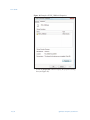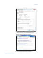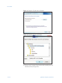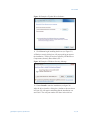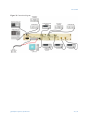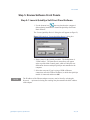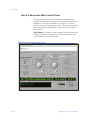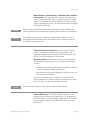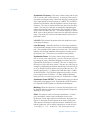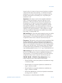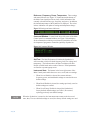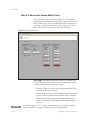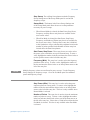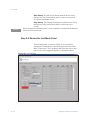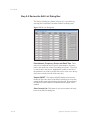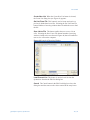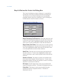
1
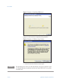
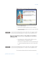
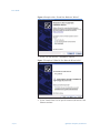
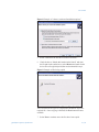
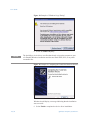
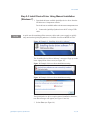
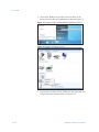
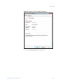
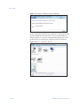
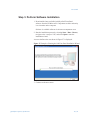
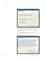
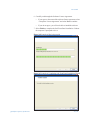
QuickSyn
®
MICROWAVE FREQUENCY SYNTHESIZER
User Guide
DOC. NO. 5580513-01 | REV. E | ECN 001540
National Instruments | 4600 Patrick Henry Drive, Santa Clara CA 95054 | 408-610-6810 | ni-microwavecomponents.com
Notices
© 2014 National Instruments
Warranty
No part of this manual may be copied,
duplicated, or reproduced in any form
or by any means (including electronic
storage and retrieval or translation
into a foreign language) without prior
agreement and written consent from
National Instruments as governed
by United States and international
copyright laws.
National Instruments warrants this
product to be free from defects in material and workmanship for one year
from the date of delivery. Damage
due to accident, abuse, or improper
signal level is not covered by the
warranty. Removal, defacement, or
alteration of any serial or inspection
label, marking, or seal may void the
warranty. National Instruments will
repair or replace, at its option, any
components of this product which
prove to be defective during the warranty period, provided the entire unit
is returned to National Instruments
or an authorized service facility.
In-warranty units will be returned
freight prepaid; out-of-warranty units
will be returned freight COLLECT.
No warranty other than the above is
expressed or implied.
National Instruments
4600 Patrick Henry Drive
Santa Clara CA 95054
Software Copyright
Original National Instruments
software may be distributed without
consent from National Instruments
only if all software and associated
files are included in the distribution
and remain unmodified.
Certification
National Instruments certifies this
instrument to be in conformance with
the specifications noted herein at time
of shipment from the factory.
Manual Change Information
As we continually improve and
update our products, changes to the
material covered by the manual will
occur. To maintain the technical
accuracy of the manual, it may be
necessary to provide new or additional information with the manual.
In these cases, the manual is shipped
with a Manual Update. Please be
sure to incorporate the information as
instructed in the Manual Update.
Safety Notices
CAUTION
A CAUTION notice denotes a
hazard. It calls attention to an
operating procedure, practice,
or the like that, if not correctly performed or adhered to,
could result in damage to the
product or loss of important
data. Do not proceed beyond
a CAUTION notice until the
indicated conditions are fully
understood and met.
WARNING
A WARNING notice defines
a hazard. It calls attention to
an operating procedure or
practice that if not correctly
followed or adhered to, could
result in either personal injury or death. Do not proceed
beyond a WARNING notice
until the indicated conditions
are fully understood and
met.
User Guide
Introducing the QuickSyn Frequency Synthesizer
Congratulations on purchasing a QuickSyn Frequency Synthesizer!
To get the most out of your purchase, it is recommended that this
User Guide be read carefully and completely.
In this document . . .
The scope of this document is to describe how to setup the
QuickSyn Frequency Synthesizer, install its software on a computer,
and control the Synthesizer using the software.
This document describes information for all QuickSyn Frequency
Synthesizer models.
“Step 1. Unpack Hardware” on page 4
“Step 2. Peform USB Device Driver Installation” on page 4
“Step 3. Perform Software Installation” on page 19
“Step 4. Setup Synthesizer” on page 22
“Step 5. Review Software Front Panels” on page 24
“Service Information” on page 42
NOTE
We recently changed the branding of the QuickSyn product line by replacing the
Phase Matrix logo with the NI logo. In some cases, as we deplete out stock, you may
observe that the Phase Matrix logo remains on packaging, software, manuals, and the
unit itself. Other than the mere change of the logo, QuickSyn products continue to
employ the same revolutionary phase-refining technology that enables blazing-fast
switching speeds and very low-noise and spurious performance in the same compact
package.
QuickSyn Frequency Synthesizer
3 of 44
User Guide
Step 1. Unpack Hardware
Inspect shipping cartons for any sign of visible or concealed
damage. If cartons are damaged, notify the carrier immediately.
CAUTION
The QuickSyn Frequency Synthesizer ships in an antistatic package to prevent
damage from electrostatic discharge (ESD). Because ESD can damage the
components of a hardware unit, store the unit an antistatic bag when not in use.
Remove the unit from its package and inspect it for loose
components or any signs of damage. Notify NI Microwave
Components if the unit appears damaged in any way.
Step 2. Peform USB Device Driver Installation
NOTE
In addition to a USB interface, other interfaces are available for order as accessories,
including Ethernet, GPIB, and RS232 interfaces.
To use a personal computer (PC) to communicate with the
QuickSyn Synthesizer, a USB device driver must be installed. The
device driver can be installed automatically or installed manually
if you are not able to run executable files on your PC. The driver
supports both 32- and 64-bit versions of Windows XP, Windows
Step 2-1 Install Device Driver Using Automatic Installation
Vista, and Windows 7. For automatic installation of the device
driver, follow the Step 2-1 instructions. To manually install the
device driver on a system using Windows XP or Windows 7,
follow the Step 2-2 or Step 2-3 respectively.
1 Download the latest available QuickSyn executable USB device
driver from the NI Microwave Components website.
Device drivers are available online at ni-microwavecomponents.com
2 Start the installation process by selecting Start > Run >
Browse, navigate to the “setup.exe” file, and select Open to
start the installation wizard.
4 of 44
QuickSyn Frequency Synthesizer
User Guide
Figure 1 Example of the QuickSyn USB Device Driver Installer
A window similar to the one shown in Figure 1 will appear.
Figure 2 Example of End User License Agreement
3Select Next to continue to the End User License Agreement.
4 Carefully read through the End User License Agreement.
•
If you agree to the terms of the software license agreement,
select “I accept this Agreement” and select Next to continue.
•
If you do not agree, you will not be able to install the software.
A window similar to the one shown in Figure 4 will appear to show
QuickSyn Frequency Synthesizer
5 of 44
User Guide
Figure 3 Example of “Installing USB Driver”
progress of various software components being installed.
Figure 4 Example of “Windows Logo Testing”
5 Select Next once the files have been copied.
NOTE
6 of 44
The QuickSyn device driver uses files that already exist on the computer as part
of a standard Windows installation and does not install EXE, DLL, or any other
executable files.
QuickSyn Frequency Synthesizer
User Guide
Figure 5 Example of Completing USB Device Driver Installer
6Select Continue Anyway.
7 Select Finish to complete the USB device driver installation.
6 Connect the QuickSyn Synthesizer to the PC using a USB Cable
and proceed to Step 3.
NOTE
A quick-start kit containing all the necessary cables and a power supply to quickly
setup and run the QuickSyn Synthesizer is available for order as MFSW-ACC06.
Step 2-2 Install Device Driver Using Manual Installation
(Windows XP)
1 Download the latest available QuickSyn USB device driver
from the NI Microwave Components website.
Device drivers are available online at ni-microwavecomponents.com
2 Connect the QuickSyn Synthesizer to the PC using a USB
Cable.
NOTE
A quick-start kit containing all the necessary cables and a power supply to quickly
setup and run the QuickSyn Synthesizer is available for order as MFSW-ACC06.
The “Found New Hardware Wizard” should start automatically.
QuickSyn Frequency Synthesizer
7 of 44
User Guide
Figure 6 Example of the “Found New Hardware Wizard”
3 Select “No, not this time” and Next to continue.
Figure 7 Example of “What Do You Want the Wizard to Do”
4 Select “Install from a list or specific location (Advanced)” and
Next to continue.
8 of 44
QuickSyn Frequency Synthesizer
User Guide
Figure 8 Example of “choose search and installation options”
5 Select “Search for the best driver in these locations.”
6 Check the box to “Include this location in the Search” and enter
the file path in the combo-box or select Browse and search for the
device driver file (QuickSyn.inf) that was downloaded in step 1.
Figure 9 Example of files being copied
The screen shown in Figure 9 is displayed as Windows copies the
required file. Once copying is finished, the Next button becomes
available.
7Select Next to continue once the files have been copied.
QuickSyn Frequency Synthesizer
9 of 44
User Guide
Figure 10 Example of “Windows Logo Testing”
8Select “Continue Anyway”
NOTE
The QuickSyn® device driver uses files that already exist on the computer as part
of a standard Windows installation and does not install EXE, DLL, or any other
executable files.
Figure 11 Example of “Completing the Found New Hardware Wizard”
Windows should display a message indicating that the installation
was successful.
9Select Finish to complete the device driver installation.
10 of 44
QuickSyn Frequency Synthesizer
User Guide
Step 2-3 Install Device Driver Using Manual Installation
(Windows 7)
1 Download the latest available QuickSyn device driver from the
NI Microwave Components website.
Device drivers are available online at ni-microwavecomponents.com
2 Connect the QuickSyn Synthesizer to the PC using a USB
cable.
NOTE
A quick-start kit containing all the necessary cables and a power supply to quickly
setup and run the QuickSyn Synthesizer is available for order as MFSW-ACC06.
Figure 12 Example of “Installing device driver software”
The “Installing Device Driver Software” message will pop up in the
lower-right portion of the screen (see Figure 12).
Figure 13 Example of driver software installation warning
Figure 14 Example of driver software installation warning
The QuickSyn device driver requires manual installation; therefore,
two other messages will appear (see Figure 13 and 14).
3Select Close (see Figure 14).
QuickSyn Frequency Synthesizer
11 of 44
User Guide
4 Click on the Windows logo in the lower-left corner of the
screen, and select Drivers and Printers as shown in Figure 15.
Figure 15 Example of How to Start Manual Installation of Driver
Figure 16 Example of Finding a Device
5 Find the device labeled “FSW_USBSerial” and right-click on it.
Choose Properties from the menu (see Figure 16).
12 of 44
QuickSyn Frequency Synthesizer
User Guide
Figure 17 Example of FSW_USBSerial Properties
6 Click on the Hardware tab (see figure 17).
QuickSyn Frequency Synthesizer
13 of 44
User Guide
Figure 18 Example of FSW_USBSerial Properties
7 Select the Properties button to display the properties dialog
box (see Figure 18).
14 of 44
QuickSyn Frequency Synthesizer
User Guide
Figure 19 Example of FSW_USBSerial Properties
8Select Change settings (see Figure 19) to enable the Update
Driver button and click on the Update Driver button.
Figure 20 Example of Update Driver Software
9 Select the browse option as shown in Figure 20.
QuickSyn Frequency Synthesizer
15 of 44
User Guide
Figure 21 Example of Update Driver Software
Figure 22 Example of Browse for Folder
10 Browse to the location of the location of the QuickSyn.inf. file
and choose Ok (see Figure 22).
16 of 44
QuickSyn Frequency Synthesizer
User Guide
Figure 23 Example of Update Driver Software
11Click Next to begin installing the driver (see Figure 23).
A Windows security dialog box will pop up asking to approve
the installation. The driver has been signed by NI Microwave
Components (formerly Phase Matrix, Inc.).
Figure 24 Example of Windows Security Message
12Choose Install to start the installation (see figure 24).
After the driver installs, a dialog box (similar to the one shown
in Figure 25) will appear confirming that the installation was
successful. The com port number will show in the title bar.
QuickSyn Frequency Synthesizer
17 of 44
User Guide
Figure 25 Example of Windows Security Message
In the Control Panel under Devices and Printers, the QuickSyn USB
interface should now be listed along with its com port number as
shown in Figure 26. Keep the com port number handy as it will be
needed in order to communicate with the QuickSyn Synthesizer.
Figure 26 Device and Printers Window
18 of 44
QuickSyn Frequency Synthesizer
User Guide
Step 3. Perform Software Installation
1 Download the latest available QuickSyn Soft Front Panel
software from the NI Microwave Components website and unzip
it to a location on the computer.
Software is available online at ni-microwavecomponents.com
2 Start the installation process by selecting Start > Run > Browse,
navigate to the “setup.exe” file, and select Open to start the
installation wizard.
A screen similar to the one shown in Figure 27 is displayed.
Figure 27 Example of Starting the Soft Fron Panel Installation Wizard
3 Continue to the next screen.
QuickSyn Frequency Synthesizer
19 of 44
User Guide
Figure 28 Example of Selecting Destination Directory for Executables
4 Enter the destination directory for the Soft Front Panel
executables or browse to a destination directory by selecting the
Browse button.
5 Once the file path has been entered, select Next to continue to
the Software License Agreement.
Figure 29 Example of Software License Agreement
20 of 44
QuickSyn Frequency Synthesizer
User Guide
6 Carefully read through the Software License Agreement.
•
If you agree to the terms of the software license agreement, select
“I accept the License Agreement” and select Next to continue.
•
If you do not agree, you will not be able to install the software.
7Select Finish to complete the Soft Front Panel installation. Reboot
the computer if prompted to do so.
Figure 30 Example of files being copied
Figure 31 Example of Completing Soft Front Panel Installation Wizard
QuickSyn Frequency Synthesizer
21 of 44
User Guide
Step 4. Setup Synthesizer
NOTE
A quick-start kit that contains all the necessary cables and a power supply to quickly
setup and run the QuickSyn Synthesizer is available for order as MFSW-ACC06.
1 Insert one end of an SMA cable to the Synthesizer’s RF OUT
SMA connector and the other end of the cable to the applicable
microwave test equipment as shown in Figure 32.
NOTE
In addition to a USB interface, other interfaces are available for order as accessories,
including Ethernet, GPIB, and RS232 interfaces.
2 Insert the Mini-B end of a USB cable into the Synthesizer’s USB
connector and the A-Type end into the computer’s USB receptacle.
3 Ensure that the power supply is turned off before connecting
DC cables (PN MFSW-ACC03). Verify that the voltage of the
power supply is set between +12 V and +12.5 V.
WARNING
Voltage less than +12 V at the Synthesizer connector may result in malfunction,
and voltage in excess of +15 V may damage the Synthesizer.
4 Connect the black (ground) wire of the DC bias power cable to
the power supply.
5 Connect the red (+12 V) wire to the power supply.
6 Insert a 20-pin SPI connector into the Synthesizer’s SPI connector receptacle.
7 Turn on the power supply.
CAUTION
22 of 44
The QuickSyn Synthesizer generates heat. Therefore, use a heatsink or ensure that
adequate airflow is present to prevent the Synthesizer’s internal temperature from
exceeding +75° C.
QuickSyn Frequency Synthesizer
User Guide
Figure 32 Connection diagram
QuickSyn Frequency Synthesizer
23 of 44
User Guide
Step 5. Review Software Front Panels
Step 5-1 Launch QuickSyn Soft Front Panel Software
1 Use the shortcut icon
that was placed on the computer’s
desktop during installation to launch the QuickSyn Soft Front
Panel software.
The “Locate QuickSyn Device” dialog box will appear (see Figure 33).
Figure 33 Example of “Locate QuickSyn Device” dialog box
2 Enter a name for the QuickSyn module. The default name is
“USBComPort.” The name that is entered here will appear
at the top of the Main Control panel, which will help the user
differentiate between multiple QuickSyn units attached to the
computer.
3 Select the com port (If you’re using a GPIB or Ethernet
connection, enter the GPIB or IP address) to which the QuickSyn
module is connected and choose OK.
NOTE
The IP address of the Ethernet adapter accessory can be found by selecting the
Network . . . option and selecting the resulting entry that matches the MAC address
of the adapter.
QuickSyn Frequency Synthesizer
24 of 44
User Guide
Step 5-2 Review the Main Control Panel
The QuickSyn Synthesizer Soft Front Panel is a graphical user
interface (GUI) that provides a quick and easy way to exercise the
Synthesizer’s extensive functionality (see Figure 34). The GUI
contains three tabs in the upper-left corner. These tabs represent the
three logical groups of functionality—main control, sweep mode,
and list mode.
Stop Button  This button is used to stop the Soft Front Panel from
reading and writing to the Synthesizer; it halts the program and is
the preferred way to exit the program.
Figure 34 QuickSyn Main Control Panel
25 of 44
QuickSyn Frequency Synthesizer
User Guide
Model Number, Serial Number, Calibration Date, Options,
Firmware Ver  The information area, located in the upper-right
corner of the Main Control panel, reveals the Synthesizer’s model
number, serial number, date of last calibration, currently installed
options, and firmware version. This information cannot be changed
with the Soft Front Panel.
NOTE
Please have the information from the main control panel readily available when
contacting NI Microwave Components regarding questions about your Synthesizer.
NOTE
For information about options available for the QuickSyn Synthesizer, refer to
the QuickSyn Synthesizer data sheet on the NI Microwave Components website
(ni-microwavecomponents.com)
External Reference Indicators  When an external reference
source is connected to the Synthesizer, the Synthesizer will
detect the (10 MHz) reference signal and lock to the source. The
DETECT and LOCK indicators will illuminate.
Reference Source  These buttons are used to select between
External and Internal reference sources. Internal is the default
selection.
•
When External is selected, the Synthesizer will detect and lock
to the user-supplied 10 MHz external signal.
•
When Internal is selected, the Synthesizer will lock to its ovencontrolled crystal oscillator.
To lock to an external reference, connect an external reference
source to the REF IN connector located on the Synthesizer’s front
panel (see Figure 32) and select the External button.
NOTE
External reference frequency input must be within 10 MHz ±2 ppm.
Internal Reference  The OUTPUT button enables the user to
choose between reference power output on or off. By default the
OUTPUT button is on and illuminated. When the OUTPUT button
is off, the signal is muted, and the OUTPUT button is no longer
illuminated.
QuickSyn Frequency Synthesizer
26 of 44
User Guide
Synthesizer Frequency  This rotary control (along with an entry
box) is used to select a fixed frequency. A frequency value may be
selected by pointing the rotary control and dragging it around to the
left or right until the desired frequency is reached. The LOCKED
indicator will illuminate when the Synthesizer settles on the target
frequency. The value is displayed in the entry box below the rotary
control. The entry box value may be changed by highlighting the
number and entering in the desired value or by using the up/down
arrows to the left of the entry box. The default frequency is 10,000
MHz. Refer to the Synthesizer’s data sheet for applicable frequency
range. Data sheets are located on the Phase Matrix website (www.
phasematrix.com).
LOCKED This indicator illuminates when the Synthesizer settles
on the target frequency.
Lock Recovery   When this check box is selected, the Synthesizer
will automatically attempt to recover a lost or unestablished frequency
lock. Three attempts will be made to recover the lock. The LOCKED
indicator will no longer illuminate if the Synthesizer cannot recover
the frequency lock. The lock recovery function is on by default.
Synthesizer Power  This rotary control (along with an entry
box) is used to select output power. A power value may be selected
by pointing the rotary control and dragging it around to the left or
right until the desired power is reached. The value is displayed in
the entry box below the rotary control. The entry box value may be
changed by highlighting the number and entering in the desired value or by using the up/down arrows to the left of the entry box. The
default output power is +15 dBm for the FSW-0010 and +13 dBm
for the FSW-0020. The FSW-0010 Synthesizer provides a leveled
power response from -25 dBm to +15 dBm, and the FSW-0020
model provides a leveled response between -10 dBm and +13 dBm.
Synthesizer Power OUTPUT  This button enables the user to choose
between RF power output on or off. By default the OUTPUT button is
off. When the OUTPUT button is on, the button will illuminate.
Blanking  When this check box is selected, RF output power will
be disabled while the Synthesizer is switching between frequencies.
Blanking is off by default.
Pulse  This button is used to select pulse modulation. To utilize
pulse modulation, connect a pulse-modulation source to the
Synthesizer’s Pulse input connector located on the front panel (see
Figure 32) and select the Pulse button on the main control panel.
The button will illuminate to indicate that pulse modulation is on,
and the Synthesizer will switch the output power on and off using
5-volt logic (i.e., +5 V = 0n and 0 V = off). Pulse input uses an
27 of 44
QuickSyn Frequency Synthesizer
User Guide
internal “pull-up” resistor to keep power on when there is nothing
connected to the Pulse input connector. To maximize the pulsemodulation on-off ratio, set the Synthesizer’s output power from
the Main Control panel to maximum power. By default pulse
modulation is off.
Amplitude  This button is used to select amplitude modulation
(AM). To utilize the AM mode, connect an AM source to the
Synthesizer’s AM input connector located on the front panel of
the Synthesizer (see Figure 32) and select the Amplitude button
on the main control panel. The button will illuminate to indicate
that amplitude modulation is on, and the Synthesizer will accept
modulating signals between DC and 100 kHz within ±1 V (2 V p-p)
amplitude. For optimal performance, set the Synthesizer’s output
power from the Main Control panel to the middle of the available
power range. By default AM is off.
AM Sensitivity %  This slider and accompanying entry box enables
the user to set AM sensitivity, which is dependent on Synthesizer
output frequency. To set the desired sensitivity, move the slider left
or right to the desired value or enter the value in the entry box.
Frequency  This button is used to select frequency modulation (FM).
To utilize the FM mode, connect an FM source to the Synthesizer’s
FM input connector located on the front panel of the Synthesizer (see
Figure 32). From the Main Control panel, select the Frequency button
and one of the four FM modes. The Frequency button will illuminate
to indicate that frequency modulation is on. The Synthesizer will accept modulating signals between ±1 V (2 V p-p). By default FM is off.
FM Sensitivity %  This slider and accompanying entry box enables
the user to set FM sensitivity, which is dependent on Synthesizer
output frequency. To set the desired sensitivity, move the slider left
or right to the desired value or enter the value in the entry box.
FM WB, FM NB 1, FM NB 2, Phase Modulation These
buttons enable the user to choose the desired FM mode.
•
When FM WB is selected, the Synthesizer modulation rate range
is 50 kHz to 1 MHz.
•
When FM NB 1 is selected, the Synthesizer modulation rate
range is 100 Hz to 10 kHz.
•
When FM NB 2 is selected, the Synthesizer modulation rate
range is 10 kHz to 100 kHz.
•
When Phase Modulation is selected, the Synthesizer modulation
rate range is DC to 100 kHz.
The Synthesizer’s default FM mode is FM WB.
QuickSyn Frequency Synthesizer
28 of 44
User Guide
Reference, Frequency, Power, Temperature   These settings
and status indicators (see Figure 35) located toward the bottom of
the Main Control panel provide an easily visible indication of the
currently selected reference type, frequency, and power. In addition,
the internal temperature of the Synthesizer is displayed. The values
in these indicators will update as settings and temperature change.
Figure 35 Settings and status indicators
Command Window   Located in the lower-left corner of the Main
Control panel is a command window (see Figure 31) that displays
all the commands used during a session and is intended to aid in the
development of programs to control the QuickSyn Synthesizer.
Figure 36 Command Window
Self Test   The Start Test button will initiate the Synthesizer’s
self-test routine, which will check frequency lock, bias voltage, and
temperature. The indicator above the Start Test button will show
Passed or Failed based on the results of the test. Failed parameters
are listed in a separate popup screen.
Instrument State   The buttons in the lower-right corner of the
Main Control panel enable the user to save, recall, and reset settings.
NOTE
29 of 44
•
When Save as Default is selected, the current reference,
frequency, power, and modulation settings are stored as the new
default settings.
•
When Recall Default is selected, the settings previously saved as
default settings are recalled.
•
When Set to Factory Default is selected, the Synthesizer’s
factory-defined default settings (see Table 1) are restored,
replacing previously user-defined settings.
When the Synthesizer is turned on, the instrument state returns to the last saved
state; thus, if no user-defined settings are saved, the factory default settings are used.
QuickSyn Frequency Synthesizer
User Guide
Table 1 Factory Default Settings
Setting
Default Value
RF Output
off
Frequency
10 GHz
Output Power
Blanking
Reference Source
Reference Output
Pulse Modulation
Amplitude Modulation
AM Sensitivity
Frequency Modulation
FM Sensitivity
QuickSyn Frequency Synthesizer
+15 dBm (FSW-0010)
+13 dBm (FSW-0020)
off
Internal
on
off
off
0
off
0
30 of 44
User Guide
Step 5-3 Review the Sweep Mode Panel
The Sweep Mode panel, as shown in Figure 37, is accessible by
selecting the Sweep Mode tab located in the upper-left corner of the
Main Control panel. The Sweep Mode panel allows the user to set
triggering, sweep direction, frequency range and step size, power
range and step size, and frequency and power dwell time.
Figure 37 Sweep Mode Panel
Set Trigger  The buttons in the Sweep Settings (Common) area
of the Sweep Mode panel allow the user to set parameters that are
common to both frequency and power sweeps.
NOTE
31 of 44
•
When No Trigger is selected, sweeps begin immediately after
selecting the Start Sweep button.
•
When Enable List Trigger is selected and the Start Sweep button is
pressed, a full sweep begins when a hardware trigger is detected.
•
When Enable List Point Trigger is selected and the Start Sweep
button is pressed, sweep points change as each hardware trigger is
received.
A hardware trigger is a 0/3.3 V pulse signal applied to pin 17 (trigger) of the SPI
interface connector. A trigger is initiated on a low-to-high transition.
QuickSyn Frequency Synthesizer
User Guide
Dwell Time (usec)  The Dwell Time entry box is used to enter the
dwell time, which is the time that each point (frequency or power)
in the sweep will remain static before moving to the next point. The
dwell time is not used when Enable List Point Trigger is selected.
To enter a dwell time, highlight the entry box and enter a value.
Use the up/down arrow on the left side to raise or lower the value.
NOTE
If the QuickSyn Synthesizer is equipped with option 03, switching speed (from one
frequency point to another) in Normal Mode is 200 μs. Sweeps can be as fast as
100 μs per point in Fast Mode. However, the number of points allowed is limited
to 32,000. Therefore, use Normal Mode for sweeps that require a number of points
over 32,000. If option 03 is not present, switching speed is 1 ms in either mode.
Blanking On/Off  When the Blanking button is turned on, RF
output is disabled until the frequency has stabilized. The indicator
on the button will illuminate when Blanking is on.
Output On/Off  This button allows the user to turn the RF output
signal on and off. By default the RF output signal automatically
turns on and remains on after a sweep is finished unless the Output
On/Off button is selected. When selected, the indicator on the
button is illuminated.
Sweep Direction  The buttons under Sweep Direction allow the
user to set sweep direction.
•
When Up is selected, sweeps occur in ascending order.
•
When Down is selected, sweeps occur in descending order.
•
When Up and Down is selected, the Synthesizer sweeps in both
ascending and descending order.
Number of Sweeps  This entry box is used to define the number
of times a sweep is executed. To enter a number of sweeps,
highlight the entry box and enter the desired value. The up/down
arrow on the left side of the entry box can be used to increase or
decrease the value.
Continuous On/Off  When this button is selected, the indicator
will illuminate, and sweeps will continue until the Stop Sweep
button is selected.
QuickSyn Frequency Synthesizer
32 of 44
User Guide
Sweep Mode  The buttons in the Frequency Sweep Settings
area of the Sweep Mode panel allow the user to set the parameters
necessary for frequency sweeps.
•
When Normal Mode is selected, the Start Freq, Stop Freq,
Power, and Step Freq entry boxes are available for the user to
enter values.
•
When Fast Mode is selected, the Start Freq, Stop Freq, Power,
and Number of Points entry boxes are available for the user
to enter values. The Step Freq entry box is disabled as the
Synthesizer will pre-calculate the step frequency based on the
number of points specified in the Number of Points entry box
located above the Start Sweep button.
Start Freq, Stop Freq  These entry boxes are used to select the
frequencies that the sweep will start and end with. To enter a value,
highlight the number in the box and enter the desired value or use
the up/down arrows to the left of the entry box.
Power (dBm)  This entry box is used to select the power
parameter of a frequency sweep. To enter a value, highlight the
number in the box and enter the desired value or use the up/down
arrows to the left of the entry box.
NOTE
Multiple power levels are not allowed in frequency sweeps. Use the Power Sweep
Settings for power sweeps. Go to the List Mode panel for combined power and
frequency sweeps.
Step Freq (MHz)  This entry box is used to select the frequency
step between sweep points. To enter a value, highlight the number
in the box and enter the desired value or use the up/down arrows to
the left of the entry box. This box is only available when Normal
Mode is selected.
Number of Points  This entry box is used to select the maximum
number of points to sweep. To enter a value, highlight the number
in the box and enter the desired value or use the up/down arrows to
the left of the entry box. Values above 32,000 are not allowed when
Fast Mode is selected. This box is only available when Fast Mode
is selected.
Start Sweep  The Start Sweep button under the Frequency Sweep
Settings area of the Sweep Mode panel is used to execute frequency
sweeps after parameters are set.
33 of 44
QuickSyn Frequency Synthesizer
User Guide
Stop Sweep  The red Stop Sweep button under the Frequency
Sweep Settings area of the Sweep Mode panel is used to halt
frequency sweeps.
Sweep Mode  The buttons in the Power Sweep Settings area
of the Sweep Mode panel allow the user to set the parameters
necessary for power sweeps.
•
When Normal Mode is selected, the Start Power, Stop Power,
Frequency, and Step Power entry boxes are available for the
user to enter values.
•
When Fast Mode is selected, the Start Power, Stop Power,
Frequency, and Number of Points entry boxes are available for
the user to enter values. The Step Power entry box is disabled
as the Synthesizer will pre-calculate this parameter based on the
number of points specified in the Number of Points entry box
located above the Start Sweep button.
Start Power, Stop Power  These entry boxes are used to select
the power value at which the sweep will start and stop. To enter a
value, highlight the number in the box and enter the desired value or
use the up/down arrows to the left of the entry box.
Frequency (MHz)  This entry box is used to select the frequency
parameter of the sweep. To enter a value, highlight the number in
the box and enter the desired value or use the up/down arrows to the
left of the entry box.
NOTE
Multiple frequency values are not allowed in power sweeps. Use the Frequency
Sweep Settings for frequency sweeps. Go to the List Mode panel for combined
power and frequency sweeps.
Step Power (dBm)  This entry box is used to select the power
output step between sweep points. To enter a value, highlight the
number in the box and enter the desired value or use the up/down
arrows to the left of the entry box. This box is only available when
Normal Mode is selected.
Number of Points  This entry box is used to select the maximum
number of points to sweep. To enter a value, highlight the number
in the box and enter the desired value or use the up/down arrows to
the left of the entry box. Values above 32,000 are not allowed when
Fast Mode is selected. This box is only available when Fast Mode
is selected.
QuickSyn Frequency Synthesizer
34 of 44
User Guide
Start Sweep  The Start Sweep button under the Power Sweep
Settings area of the Sweep Mode panel is used to execute power
sweeps after parameters are set.
Stop Sweep  The red Stop Sweep button under the Power Sweep
Settings area of the Sweep Mode panel is used to halt power
sweeps.
NOTE
When exiting the Sweep Mode panel, a reset command is issued and the Synthesizer
returns to its last saved state.
Step 5-4 Review the List Mode Panel
The List Mode panel, as shown in Figure 38, is accessible by
selecting the List Mode tab located in the upper-left corner of the
Main Control panel. The List Mode panel allows the user to setup
and execute a list of triggered sequences of Synthesizer states.
Figure 38 List Mode Panel
35 of 44
QuickSyn Frequency Synthesizer
User Guide
Set Trigger  The buttons in the Set Trigger area of the List Mode
panel allow the user to select trigger mode.
NOTE
•
When No Trigger is selected and the Run List button is pressed,
sweeps begin immediately upon execution.
•
When Enable List Trigger is selected, a full sweep begins when
a hardware trigger is detected.
•
When Enable List Point Trigger is selected, sweep points
change as each hardware trigger is received.
A hardware trigger is a 0/3.3 V pulse signal applied to pin 17 (trigger) of the SPI
interface connector. A trigger is initiated on a low-to-high transition.
Dwell Time  The buttons in the Dwell Time area of the List Mode
panel allow the user to choose between List Point Dwell Time and
Global Dwell Time. Dwell time is the time that each point in the
sweep will remain static before moving to the next point
•
When Use List Point Dwell Time is selected, the Synthesizer
uses the user-specified time value for each list point.
•
When Global Dwell Time is selected, the Global Dwell Time
entry box becomes available, and a value in microseconds can
be entered.
Global Dwell Time  This entry box is used to specify the time
in microseconds that each point will remain static before moving
to the next point. To enter a value, select the option button next to
Global Dwell Time, highlight the number in the box, and enter a
value or use the up/down arrows.
Sweep Direction  The buttons under Sweep Direction allow the
user to set sweep direction.
QuickSyn Frequency Synthesizer
•
When Up is selected, sweeps occur in ascending order.
•
When Down is selected, sweeps occur in descending order.
•
When Up and Down is selected, the Synthesizer sweeps in both
ascending and descending order.
36 of 44
User Guide
Number of Sweeps  This entry box is used to define the number
of times a sweep is executed. To enter a number of sweeps,
highlight the entry box and enter the desired value. The up/down
arrow on the left side of the entry box can be used to increase or
decrease the value.
Continuous On/Off  When this button is selected, the indicator
will illuminate, and sweeps will continue until the red Stop List
button is selected.
Blanking On/Off  When the Blanking button is turned on, RF
output is disabled until frequency has stabilized. The indicator on
the button will illuminate when Blanking is on.
Erase List  When the Erase List button is selected, an erase-list
command is sent and prepares the Synthesizer for a new list.
Create/Edit List  This button is used to enable the Edit List dialog
box (see Figure 34).
Run List  The Run List button is used to execute a sweep per a list
that has been created in the Edit List dialog box.
Stop List  The Stop List button is used to halt a sweep running in
list mode.
List Load Progress  The List Load Progress indicator displays
the progress of the list loading after the Load Current List button
in the Edit List dialog box is selected. The Ready indicator will
illuminate when the list is loaded and ready to be executed.
Run List Point  This button is used to set the parameter in the
list for the point number specified in the Point Number entry box
located next to the Run List Point button.
Point Number  The Point Number entry box is used to specify the
point number in the list that is being created or edited in the Edit
List dialog box. To specify a value, highlight the number in the box
and enter a new value or use the up/down arrows on the left side of
the entry box.
NOTE
37 of 44
When exiting the List Mode panel, a reset command is issued and the Synthesizer
returns to its last saved state.
QuickSyn Frequency Synthesizer
User Guide
Step 5-5 Review the Edit List Dialog Box
The Edit List dialog box, shown in Figure 39, is accessible by
selecting the Create/Edit List button on the List Mode panel.
Figure 39 Edit List Dialog Box
Point Number, Frequency, Power and Dwell Time  These
entry boxes enable the user to specify point number, frequency,
power, and dwell time values for creating sweep lists. To specify
a value in these entry boxes, highlight the number in the box of
the parameter you wish to set and enter a new value or use the up/
down arrows on the left side of the entry box.
Output ON/OFF  The Output ON/OFF buttons located next to
the Dwell Time entry boxes in the Edit List dialog box are used to
control the RF output signal at the specified point. When selected
the indicator on the button will illuminate and RF output will be
enabled.
Clear Current List  This button is used to clear data in all entry
boxes in the Edit List dialog box.
38 of 44
QuickSyn Frequency Synthesizer
User Guide
Create New List  When the Create New List button is selected,
the Create List dialog box (see Figure 41) appears.
Get List From File  This button is used to locate and retrieve a
previously defined and saved list. Selecting the Get List From File
button launches a browsing window that will enable the user to find
the file.
Save List to File  This button enables the user to save a list to
a file. Selecting the Save List to File button launches a browsing
window (similar to the one shown in Figure 40) that will enable the
user to save a file on the computer.
Figure 40 Example of Browsing Window
Load Current List  This button is used to load a list into the
Synthesizer from the the Edit List dialog box.
Cancel  The Cancel button in the Edit List dialog box closes the
dialog box and does not save the values entered in the entry boxes.
QuickSyn Frequency Synthesizer
39 of 44
User Guide
Step 5-6 Review the Create List Dialog Box
The Create List dialog box, shown in Figure 41, is accessible by
selecting the Create New List button in the Edit List dialog box.
The entry boxes on the Edit List dialog box are automatically
populated when the entry boxes within the Create List dialog box
are filled and the Create List button is selected.
Figure 41 Create List Dialog Box
Begin Frequency, End Frequency  These entry boxes are used
to specify the initial and final frequency values the list will start and
end with. To enter values, highlight the number in the entry box and
enter a value or use the up/down arrow on the left side of the box.
Begin Power, End Power  These entry boxes are used to specify
the initial and final power values the list will start and end with. To
enter values, highlight the number in the entry box and enter a value
or use the up/down arrow on the left side of the box.
Dwell Time  This entry box is used to specify the dwell time for
all points on the list. To enter values, highlight the number in the
entry box and enter a value or use the up/down arrow on the left side
of the box.
Number of Points  The number of points to be included in the
list is entered in the Number of Points entry box. To enter values,
highlight the number in the entry box and enter a value or use the up/
down arrow on the left side of the box.
RF Output  The RF Output button, when pressed, disables RF
output at each point on the list. The button is illuminated when on.
Pulse Mod.  This button is used to turn on and off the pulse
modulation mode for each point on the list. The button is
illuminated when on.
40 of 44
QuickSyn Frequency Synthesizer
User Guide
Create List  Selecting the Create List button executes the action of
populating the entry boxes in the Edit List dialog box.
Cancel  The Cancel button in the Create List dialog box, closes the
dialog box and does not save the values entered in the entry boxes.
QuickSyn Frequency Synthesizer
41 of 44
User Guide
Service Information
Periodic Maintenance
There are no hardware adjustments within QuickSyn Synthesizers.
NI Microwave Components recommends that the QuickSyn
Synthesizer is calibrated every 24 months or whenever a problem
is suspected. The specific calibration interval depends upon the
accuracy required. No periodic preventive maintenance is required.
NOTE
Calibration software is available from the NI Microwave Components website
(ni-microwavecomponents.com)
Product Identification
Each QuickSyn Synthesizer is identified by three sets of numbers:
the model number (FSW-0010 is shown in this example), a
configuration-control number (CCN), and a serial number (S/N).
These numbers are located on a label affixed to the top of the
Synthesizer. The model number, CCN, serial number, and numbers
of options must be included in correspondence regarding your
Synthesizer.
Figure 42 Example of Product Identification Label
Model Number
Configuration Control Number
Serial Number
42 of 44
QuickSyn Frequency Synthesizer
User Guide
Factory Service
If you are returning a QuickSyn Synthesizer for service or repair, be
sure to include the following information with the shipment:
•
Name and address of owner
•
Model, complete serial number, options, and firmware version.
•
A complete description of the problem. Be sure to provide
enough information so that the problem can be verified:
•
Under what conditions did the problem occur?
•
Did the unit work then fail?
•
What other equipment was connected to the Synthesizer
when the problem occurred?
•
The name and telephone number of someone familiar with the
problem who can be contacted by Phase Matrix if any further
information is needed.
•
The shipping address to which the Synthesizer is to be returned.
Include any special shipping instructions.
Shipping Instructions
1 Place the Synthesizer in an antistatic bag or enclosure.
2 Wrap the Synthesizer in heavy plastic or kraft paper.
3 Repack the Synthesizer in the original container, if available.
If the original container cannot be used, pack the Synthesizer
in a heavy (275 pound test) double-walled carton with
approximately four inches of packing material between the
Synthesizer and the inner carton.
4 Seal the carton with strong filament tape or strapping.
5 Mark the carton to indicate that it contains a fragile electronic
instrument.
6 Ship the Synthesizer to Phase Matrix at the following address:
NI Microwave Components
4600 Patrick Henry Drive
Santa Clara CA 95054
Tel: 1-408-610-6810
QuickSyn Frequency Synthesizer
43 of 44
User Guide
DECLARATION OF CONFORMITY
Manufacturer’s Name:
NI Microwave Components
Manufacturer’s Address: 4600 Patrick Henry Drive
Santa Clara CA 95054
Product Name:
QuickSyn Synthesizer
Model Number:
FSW-0010, FSW-0020
Statement:
Phase Matrix, Inc. declares that the aforementioned product(s) conform(s) to the following
Council Directives of the European Union:
Low Voltage Directive 2006/95/EC
Electromagentic Compatibility (EMC) Directive 2004/108/EC
Test method(s) used*:
EN/IEC 61010-1:2001—Safety requirements for electrical equipment for measurement,
control, and laboratory use.
EN 55011:2007—Industrial, scientific, and medical (ISM) radio-frequency Equipment.
Electromagnetic disturbance characteristics. Limits and methods of measurement
EN/IEC 61326-1:2006—Electrical Equipment for Measurement, Control, and Laboratory use.
Related data*:
MIL-STD-461E (RE102 & RS103)—DoD Interface Standard: Requirements for the
Control of Electromagnetic Interference Characteristics of Subsystems and Equipment
(10 kHz to 40 GHz).
FCC 15B/ICES-003 CLASS A—Conducted and radiated emmissions.
*Independently audited by BACL Labs. Test reports on file for review. Contact NI Microwave
Components (ni-microwavecomponents.com) for more information.
Authorized Signature:
10-28-14
Mark Espinosa
Quality Assurance Manager
Date
TEMPLATE PN: T006, REV. 2
44 of 44
QuickSyn Frequency Synthesizer