1
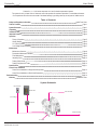
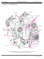
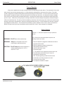
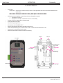
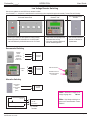
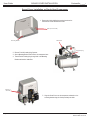
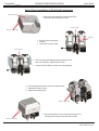
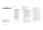
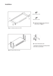
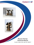
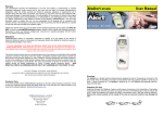
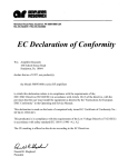
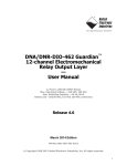
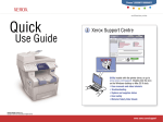
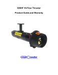
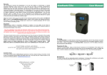
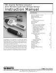
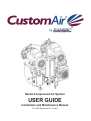
®
®
Dental Compressed Air System
USER GUIDE
Installation and Maintenance Manual
For 1000 Series with C1 Control
User Guide
CustomAir®by RAMVAC®
Thank you for selecting a CustomAirby RAMVAC Dental Compressed Air System to serve your dental facility.
CustomAirby RAMVAC compressors use proven oil-less technology to set new standards in compressed air system performance, durability and
economy.
Invest a few minutes of your time and:
1.
Read the “Maintenance” section in this guide. Use these simple preventive procedures that will allow your
compressor to reach its service-life potential.
2.
Read the “Operation” section in this guide.
Find out how to best control your compressor and put its safety features to work for you.
3.
Initiate the warranty. Check inside the back cover to review our warranty commitment to you ... and what you
need to do to receive warranty coverage.
To initiate the warranty you must: 1. Complete and return the Installation Checklist to RAMVAC.
or
2. Visit our website at www.ramvac.com and complete the warranty initiation form.
All of us at RAMVAC® appreciate your business and take a personal interest in your satisfaction. Please let us know how the system is working for
you. Just give us a call or stop by one of our dental show exhibits. Please accept my personal invitation to visit our manufacturing facility in the
beautiful Black Hills of South Dakota.
Matt Olson
General Manager, RAMVAC® Dental Products. Inc.
(800) 5-RAMVAC
(800) 572-6822
Safety and Regulatory Information
CustomAirby RAMVAC compressors meet the most current and highest safety standards. CustomAirby RAMVAC compressors are UL 60601 classified,
comply with NFPA 99C Level 3 gas system requirements, and are manufactured in a FDA Registered, ISO 9001:2000 and ISO 13485:2003
certified facility.
Here’s what you need to do to ensure the safety potential of this equipment is achieved:
• Make sure your equipment is installed according to our written instructions and the Installation Checklist is completed.
If you have purchased your CustomAir compressor from an authorized dealer, the dealer is responsible for presenting you with
the completed checklist.
• Equipment not suitable for use in the presence of a flammable anesthetic mixture with air or with oxygen or nitrous oxide.
• Type of protection against electrical shock: “Class 1”
• Degree of protection against elecrical shock: “Type B”
• The C1 Control is designated “IPX0” and must be protected from ingress of water.
The C1 Control label includes safety symbols with special meanings:
This means there is more
information available in this
User Guide.
Inside Front Cover
This stands for a “Type B Applied Part”,
which means the equipment is approved for
patient contact.
SOF_7.5.1-07-04
Effective date: 02-Jul-08
CustomAir®by RAMVAC®
User Guide
CustomAirby RAMVAC 1000 series compressor is a Level 3 dental compressed air system.
The system is run by a “state of the art” electronic control that provides for continuous operation in a controlled environment.
Our compressors are built to serve the needs of the dental industry, by providing clean dry air and years of reliable service.
Table of Contents
Safety and Regulatory Information
Table of Contents
System Schematic
Unpacking
Installation Data
Important Features
Operation
Theory of Operation
Getting Started
C1 Control Features
Low Voltage Remote Switching
Maintenance
Maintenance Overview
Preventative Maintenace Schedule
Filter Maintenance
Inspecting Dryer
Testing Safety Valves
Testing Compressor for Leaks
Specifications
Sound Cover Installation
Sound Cover Installation on Single Head Compressor
Sound Cover Installation on Dual Head Compressor
Troubleshoooting
Warranty
Inside Front Cover
Page 1
Page 1
Page 2
Page 3
Page 4
Page 5
Page 5
Page 6
Page 7
Page 8
Page 8
Page 9
Page 10
Page 10
Page 10
Page 11
Page 12
Page 14
Page 16
Inside Back Cover
System Schematic
Remote Panel
Breaker Box
Fresh air intake
(Low Voltage)
Recepticle
Facility Plumbing
C1 Control
SOF_7.5.1-07-04
Effective date: 02-Jul-08
Page 1
User Guide
UNPACKING
CustomAir®by RAMVAC®
Unpacking Instructions for the CustomAirby RAMVAC Compressor
1. Carefully remove the shipping carton from the pallet containing the compressor.
2. Visually inspect the entire compressor for shipping damage.
a. Visually inspect the motor isolator mounts for tearing.
b. If shipping damage is found, immediately contact the freight carrier and supplier.
3. Remove lag screws holding the compressor to shipping pallet.
4. Verify additional parts shipped with the compressor:
a. Additional parts shipped with all compressor models:
• Supply Hose, 1/4”mpt x 3/8”mpt, 6’ in length
• Drain tubing, 3/8” plastic, 4’ in length
• Bushing, 1/2”mpt x 3/8”fpt
b. Additional parts shipped with 1022 model only:
• Air Intake tubing, 1/2” OD plastic, 10’ in length
A Sound Reduction Cover is available for most models when installed in a sound sensitive area.
Remember to fill out and mail in the Installation Checklist to intiate the warranty !!!
Page 2
SOF_7.5.1-07-04
Effective date: 02-Jul-08
CustomAir®by RAMVAC®
INSTALLATION DATA
User Guide
Placement
•
•
•
•
•
Indoor use only, in a dust free, climate controlled room.
DO NOT install in an enclosed area where ambient temperature could exceed temperature specifications of
below 0º C / 35º F or above 40º C / 104º F while the compressor is running.
Maintain minimum 6” clearance on sides, back, and top of all compressors. Maintain 12” clearance in front of compressor.
On the 1029T compressor maintain a 12” clearance on left side for electrical service.
Compressors are equipped with 4 adjustable rubber feet, to ensure unit stands firmly on the floor.
WARNING: DO NOT install on surfaces with more than a 5º incline.
WARNING: To prevent tipping during transport securely fasten unit to shipping pallet.
CAUTION: Danger of fire or explosion when using flamable substances.
CAUTION: Never leave children unattended when compressor is in use.
Electrical
•
•
•
•
•
•
Follow NEC, NFPA 99C, and all local codes.
Compressors are shipped with the appropriate electrical cord with plug.
Qualified personnel must install a dedicated electrical circuit.
Motors and C1 Control protection is provided by a 20 amp time delay fuse on each power leg in the C1.
1029T compressor motor electrical protection is provided by a 30 amp time delay
fuse on each power leg in the Motor Control Box.
See “Specifications” for more electrical information.
WARNING: Electrical shock could occur as a result of improper grounding.
• This product must be grounded according to NEC regulations and local codes.
WARNING: Always turn off compressor and remove power plug from outlet when servicing.
CAUTION: Use of an extension cord is not advisable. An undersized extension cord will cause
a drop in line voltage and loss of power. Overheating will result.
Plumbing Connections
• Attach drain tubing to fitting on bottom of coalescing filter and direct it into floor drain for disposal of water.
• Connect compressor air outlet to facility plumbing with provided supply hose (1/4”npt x 3/8”npt, 6’ in length) and if necessary
•
a bushing (1/2”mpt x 3/8”fpt) .
Note: Pressure regulator is customer supplied.
Connect Fresh Air Intake (uses 1” hose barb) to external air source per NFPA 99C recommendations.
WARNING: Property damage and / or personal injury may result if directions are not followed or
OEM parts are not used.
CAUTION:
SOF_7.5.1-07-04
Effective date: 02-Jul-08
Connect only equipment suitable for listed maximum pressure of the compressor.
If vital equipment is used, an alternative air source should be available in case of equipment failure.
Page 3
User Guide
IMPORTANT FEATURES
CustomAir®by RAMVAC®
CustomAirby RAMVAC Important Features
Intake filter
Compressor Heads
Desiccant Dryer Cartridge
Safety valve
Particulate Filter
Safety valve
Isolator
Mounts
(4 per motor)
Lift Handle
Loops
Tank Moisture
Indicator
Safety Valve
Heat Exchanger
and Fan
Shut-off Valve to
facility plumbing
C1 Control
Pressure Gauge
Filter Drain Fitting
Filter Indicator
Coalescing Filter
Model 1025D is pictured. Other models have identical features with the exception
of model 1029T, which has a motor control box on the left end.
Page 4
SOF_7.5.1-07-04
Effective date: 02-Jul-08
CustomAir®by RAMVAC®
User Guide
OPERATION
Theory of Operation
When power is applied, fresh air is taken in through air filters and compressed by the pump pistons. The compressed air is very warm
and is cooled for use by the heat exchanger and fan. Air is then delivered to coalescing filter to remove most of the moisture. The coalescing filter is equipped with a automatic draining feature that allows the draining of the excess moisture. The cool air enters the desiccant style
dryer assembly to complete the moisture removal by removing 99.7% of the water vapor from the air. Air is directed into the dryer cartridges,
from one to the other, by electronically controlled solenoid valves. The timing for the solenoid valves is varied between models and provided
by the C1 Control. While the air is moving through one cartridge, the desiccant in the other cartridge is being dried by air directed through an
orifice in the outlet shuttle valve. This valve cycle will be noticeable by a short burst of air from the purge valves. When the air has left the dryer
assembly it goes through a particulate filter to remove any remaining particulates from the air. It is then collected in the tank where a pressure
gauge displays the tank air pressure. The tank pressure is monitored by a pressure transducer in the C1 Control, which runs the motors on
demand. Pressure is factory set to start the compressor at 80 psi and shut off at 100 psi. Pressure settings are not adjustable.
Getting Started
CustomAirby RAMVAC 1000 series compressor is easy to operate and
maintain.
WARNING: DO NOT direct air flow toward the body.
WARNING: Always turn off compressor and remove
power plug from outlet when servicing.
CAUTION: DO NOT attempt to operate the compressor at
ambient temperature below 0º C / 35º F or
above 40º C / 104º F.
SOF_7.5.1-07-04
Effective date: 02-Jul-08
Note: If Sound Cover was ordered with the compressor see
“Installing Sound Cover” section.
1. Verify the compressor is plugged into a dedicated circuit with an
appropriate electrical outlet.
2. Verify the compressor is properly connected to the
facility plumbing and fresh air source.
3. Verify the outlet valve is closed.
4. Vent pressure gauge
a. Turn yellow tab on top of gauge from closed to open to vent.
5. Push and hold the power button on the C1 Control for
approximately 5 seconds to start.
Note: The power light will go off when the button is held.
6. Test for leaks. See “Testing Compressor for Leaks”.
7. Turn the shut off valve to open.
8. The compressor installation is complete.
Page 5
OPERATION
User Guide
CustomAir®by RAMVAC®
C1 Control Features
•
•
•
•
•
•
•
•
•
•
Status Lights
Power Status - Green light is on when line voltage is present. Green light flashes when one motor has been disabled by motor
disable button.
Motor 1 Status - Green light is on when motor is running. Amber light is on when motor is disabled.
Motor 2 Status - Green light is on when motor is running. Amber light is on when motor is disabled.
Monitors the pressure transducer to start and stop the motors, depending on demand.
1. Turns motors off at 100 psi.
2. Turns motors on at 80 psi. 2nd motor will start with a 1 second delay.
Provides a 24VAC low voltage signal to the remote panel.
Accepts the remote switch input.
Controls the dryer purge function.
Communicates with the RAMVAC OWL™.
Runs the heat exchanger fan while the compressor motor(s) are on.
Flashes the maintenance light on the remote switch or OWL™ controller when filter maintenance is due.
Keeps track of run time hours with the hour meter.
Motors are protected with a 20 amp slow blow fuse on each leg.
Motor 1
Motor 2
Hour Meter
Heat Exchanger Fan
& Purge Valves
Line Voltage
Fuse, 20 amp
slow blow (2)
Status lights
Page 6
From Tank
SOF_7.5.1-07-04
Effective date: 02-Jul-08
CustomAir®by RAMVAC®
OPERATION
User Guide
Low Voltage Remote Switching
Use to turn system on and off from a remote location
Your CustomAirby RAMVAC compressor is manufactured to continuously cycle as required throughout the workday. Power off at end of the day.
Illuminated Remote Panel
RAMVAC® OWL™
• Switch light is steady-on when system is running normally.
• Switch light flashes for maintenance or one of the heads
has been disabled by the disable button on the C1 Control.
• LEDs beside corresponding switch
illuminated when running.
• OWL gives complete breakdown of
data on selected equipment
Non-Illuminated remote
Switches
• Non-illuminated switches
provide no indication for
system status.
Recommended Switching
RAMVAC
Remote
Panel or
equivelent with
illuminated
24VAC Switch
1.
F.
2.
G.
3.
H.
RAMVAC
OWL
A.
B.
C.
5.
6.
A.
B.
C.
5.
6.
C1 Control
Terminals
C1 Control
Terminals
OWL Connection
RAMVAC Panel or
Alternative Switch
Connection
Alternative Switching
Toggle Switch
or other
non-illuminated
switch
(option)
F.
H.
C1 Control
Terminals
Note: Maximum wire length for low
voltage 18 gauge wire :
Vac Switch
Vac Light
Common
Illuminated Remote Switch
SOF_7.5.1-07-04
Effective date: 02-Jul-08
F - +24 VAC
G - +24 VAC
H - AC Common
500 feet
Note: High Voltage switching is an
option but not recommended. Contact
RAMVAC.
C1 Controller
Terminals
Page 7
User Guide
CustomAir®by RAMVAC®
MAINTENANCE
Maintenance Overview
CustomAirby RAMVAC compressor preventive maintenance is simple, clean, and inexpensive.
It can help ensure your system provides years of predictable performance.
Key points for trouble-free operation:
• Check the Coalescing and Particulate filter indicator every month.
• Keep compressor clean and free of dirt.
• Keep area surrounding compressor free of debris.
• Maintain a controlled ambient temperature between recommended levels.
• High temperatures will shorten the life of the air compressor.
• Follow the recommended preventative maintenance schedule.
Preventive Maintenance Schedule
This is a recommended schedule for a compressor in a clean, dry environment.
Any site other than specified will decrease the maintenance time exponentially.
Test for Air Leaks
1st Week and Annually
Replace Intake Filters
Annually
Replace Coalescing Filter
Replace annually or when filter indicator moves
to completely red when unit is running
Replace Particulate Filter
Replace annually or when filter indicator moves
to completely red when unit is running
Inspect Dryer
Annually
Test Safety Valves
Annually
Replace Dessicant Cartridges
Every 5 years
To reset maintenance light press and hold Motor 1 Disable and Motor
2 Disable buttons at the same time until amber lights blink once.
Page 8
SOF_7.5.1-07-04
Effective date: 02-Jul-08
CustomAir®by RAMVAC®
User Guide
MAINTENANCE
Filters
Replacing Intake Filter
Intake Filter Cap
(Turn to remove)
Note: All models use the same intake filter (1 for each head).
1.
2.
3.
4.
5.
6.
7.
Turn compressor off with the power button on the C1 Control.
Unplug compressor from outlet.
Remove intake filter cap by pressing down and rotating.
Remove intake filter and discard.
Install replacement filter and filter cap.
Plug power cord into outlet.
Return compressor to service.
Intake Filter
Element
Intake Filter (1 on
each head)
Fresh air Intake
Replacing Coalescing Filter
Note: All models use the same coalescing filter.
1.
2.
3.
4.
5.
6.
7.
8.
9.
Turn compressor off with the power button on the C1 Control.
Unplug compressor from outlet
Bleed air from system.
Push up slightly and turn coalescing filter bowl slightly and
remove.
Remove filter by turning completely out.
Install new .5 micron filter.
Position filter bowl, push up slightly and turn into place.
Plug power cord into outlet.
Return compressor to service.
Particulate Filter
Bowl
Replacing Particulate Filter
FIlter Indicator
Note: All models use the same particulate filter.
1.
2.
3.
4.
5.
6.
7.
8.
9.
Turn compressor off with the power button on the C1 Control.
Unplug compressor from outlet
Bleed air from system.
Push up slightly and turn particulate filter bowl slightly and
remove.
Remove filter by turning completely out.
Install new .01 micron filter.
Position filter bowl, push up slightly and turn into place.
Plug power cord into outlet.
Return compressor to service.
Coalescing Filter
Element
Coalescing Filter
Bowl
SOF_7.5.1-07-04
Effective date: 02-Jul-08
Filter Drain
Page 9
User Guide
MAINTENANCE
CustomAir®by RAMVAC®
Inspect Dryer
1. Operate the compressor until the pressure of the tank
reaches at least 45 psi.
2. Turn the compressor off with the Power button on
the C1 Control.
3. Carefully open the tank petcock .
4. If no water drains from the tank when the valve is opened the
dryer is working and go to step 6.
5. If water drains from the tank when the valve is opened the
dryer is not working. See “Dryer Service Procedure” on web
at www.ramvac.com or contact RAMVAC® at 1-800-572-6822.
6. Return compressor to service.
C1 Control
Test Safety Valves
1. Run compressor until 45 psi shows on the gauge.
2. While the compressor is still running, pull ring on safety valve.
Pressure Gauge
Tank Petcock
Note: A loud burst of escaping air will be heard when air is
released from the safety valve.
3. If no air comes out of safety valve, the valve is defective and valve
must be replaced immediately.
Caution: Bleed air from system before servicing.
4. Repeat procedure for each safety valve. (one for each head plus
one at tank inlet)
5. Return compressor to service.
Test Compressor for Leaks
1.
2.
3.
4.
5.
Close valve to facility plumbing.
Run compressor until it shuts off at 100 psi.
Turn compressor off with the power button on the C1 Control.
Let compressor set for 5 minutes.
If the pressure drop is more than 5 psi in a 5 minute time period,
leaks must be repaired.
6. Repair if needed.
7. Open valve to facility plumbing.
8. Return compressor to service.
Page 10
Safety Valve
Safety Valve
Safety Valve
SOF_7.5.1-07-04
Effective date: 02-Jul-08
CustomAir®by RAMVAC®
SPECIFICATIONS
User Guide
Specifications
MODEL
1022
1013D/1023D
1025D
1027D
1029T
MAX USERS
2
3
5
7
9
Motor per
Unit
1
2
2
2
3
Hp per
motor
1 hp
½ hp
¾ hp
1 hp
1hp
MOTOR
VOLTAGE
(Recommended) BREAKER
SIZE
(Recommended)
Fusetron Size
UNIT POWER
CONSUMPTION
UNIT
DIMENSIONS
(w x d x h)
230V
115V / 230V
230V
230V
230V
( 208 - 253 )
( 208 - 253 )
( 208 - 253 )
( 208 - 253 )
( 208 - 253 )
20 amp
20amp
20 amp
20 amp
20amp
FRN 8
FRN 25
FRN 8
FRN 8
FRN 25
5.1 amps
12.0 amps /
5.9 amps
8.4 amps
9.5 amps
15.4 amps
WO / SOUND
COVER
24” x 20.5” x 28”
W / SOUND
COVER
25” x 20.5” x 30”
30” x 27” x 30”
30” x 27” x 30”
30” x 27” x 30”
N/A
WEIGHT
136 lbs.
166 lbs.
174 lbs.
182 lbs.
238 lbs.
TANK SIZE
10 gallon
10 gallon
10 gallon
10 gallon
10 gallon
WO / SOUND
COVER
70
73
75
77
78
W / SOUND
COVER
58
61
63
65
N/A
3.15
3.30
4.39
6.13
9.04
Db
LEVELS
SCFM @ 100 lbs
24” x 20.5” x 26.5” 24” x 20.5” x 26.5” 24” x 20.5” x 26.5”
27” x 22” x 36”
Note: All motors used are 1 phase, 60Hz motors.
Ensure compliance with all National and Local codes.
Compressor Model Numbering System
XXXX X
compressor series #
compressor voltage
1 = 115V
2 = 230V
SOF_7.5.1-07-04
Effective date: 02-Jul-08
# of motors per unit
D = Dual
T = Triple
# of users
Page 11
User Guide
SOUND COVER INSTALLATION
CustomAir®by RAMVAC®
Sound Cover Installation on Single Head Compressor
1. Remove the 4 bolts holding the mounting bracket to the
Sound Cover and set bolts aside to reuse.
Bolts (2 on each side)
Mounting Bracket
Intake Filter
Fresh Air Piping
2. Remove Fresh Air Intake piping if present.
3. Secure Mounting Bracket with 4 bolts to the compressor base.
4. Thread Fresh Air Intake piping through hole in the Mounting
Bracket and attach to intake filter.
Bolts (2 on
each side)
5. Align the Sound Cover over the compressor and attach to the
mounting bracket using the 4 bolts previously set aside.
Page 12
SOF_7.5.1-07-04
Effective date: 02-Jul-08
User Guide
CustomAir®by RAMVAC®
Notes
SOF_7.5.1-07-04
Effective date: 02-Jul-08
Page 13
CustomAir®by RAMVAC®
User Guide
SOUND COVER INSTALLATION
Sound Cover Installation on Dual Head Compressor
Mounting Bracket
1. Remove the 4 bolts holding the mounting bracket to the
Sound Cover and set bolts aside to reuse.
Fresh Air Intake
Bolts (2 on each side)
Bolts (2)
2. Remove Fresh Air Intake piping
if present.
3. Loosen bolts on fresh air intake.
Fresh Air Intake
4. Tilt the mounting bracket slightly downward and slide onto the
base of the compressor, under the fresh air intake.
5. Line up the fresh air intake to the hole in the mounting bracket.
6. Secure mounting bracket with 4 bolts to the compressor base.
7. Tighten bolts on fresh air intake.
8. Attach Fresh Air Intake piping.
Bolts (2 on each side)
Bolts (2 on each side)
Page 14
8. Align the Sound Cover over the compressor and attach to the
mounting bracket using the 4 bolts previously set aside.
SOF_7.5.1-07-04
Effective date: 02-Jul-08
CustomAir®by RAMVAC®
User Guide
Notes
SOF_7.5.1-07-04
Effective date: 02-Jul-08
Page 15
User Guide
TROUBLESHOOTING
Symptom
Compressor does not start.
Possible Cause(s)
1. No line voltage.
No power light on C1 Control.
Compressor runs but pressure does not
increase.
Compressor gets too hot
CustomAir®by RAMVAC®
Solution
1. Restore line voltage.
a. Check the power cord to make sure it is
plugged in.
b. Check the fuse or breaker panel.
2. Blown fuse(s) in the C1 Control or motor
box( on 1029T).
2. a. Check fuse(s) in the C1 Control or motor
control box.
1. Leaks in compressor fittings.
1. See “Test Compressor for Leaks”
2. Leaks in facility air lines.
2. Test facility air lines for leaks
3. Dirty intake filters.
3. Replace intake filters
4. Dryer malfunction.
4. Contact RAMVAC®
5. Valves sticking.
5. Contact RAMVAC®
1. Ambient temperature exceeds 40ºC/
104ºF.
1. Lower ambient temperature
2. Compressor not shutting off.
2. See symptom “Compressor runs but
pressure does not increase.
Compressor runs when pressure is not being
used.
1. Leaks in compressor fittings
1. See “Test Compressor for Leaks”
2. Leaks in facility air lines.
2. Test facility air lines for leaks.
Compressor starts and shuts off more frequently than normal.
1. Condensate in tank.
1. Contact RAMVAC®
2. Leaks in compressor fittings.
2. See “Test Compressor for Leaks”
3. Leaks in facility air lines.
3. Test facility air lines for leaks.
Page 16
SOF_7.5.1-07-04
Effective date: 02-Jul-08
CustomAir®by RAMVAC®
WARRANTY
User Guide
RAMVAC® Product Support Services
The DentalEZ Group and its employees are proud of the products we provide to the dental community. We stand behind these products with a
warranty against defects in material and workmanship as provided below.
In the event that you experience difficulty with the application or operation of any of our products, please contact our customer service department
at our expense at (866) DTE-INFO.
If we cannot resolve the issue by telephone, we will arrange for a representative to contact you or suggest that the product be returned to our factory for inspection.
If product return or repair is required, we will provide you with a Return Authorization number and shipping instructions to return the product to
the proper facility. If the product is under warranty we will ask you to provide proof of purchase such as a copy of your invoice. Please be sure to
include the Return Authorization number on the package you are returning. Products returned without a return authorization number cannot
be repaired.
Freight costs for product returns are the responsibility of the customer. Products under warranty will be repaired or replaced, at our sole discretion,
and returned at our expense. Products outside the warranty limits will be repaired and returned with costs invoiced to the customer. We are not
responsible for shipping damages. We will, however, help you file a claim with the freight carrier. Written repair estimates are available.
DentalEZ warrants all equipment and parts to be free of defects in material and workmanship, under normal usage, under the following terms:
RAMVAC Products:
RAMVAC® Dental Vacuum System
RAMVAC® Vacuum Pumps only
RAMVAC® OWL™
CustomAir®by RAMVAC®
Warranty Period:
2 Years from date of installation*
10 Years from date of installation*
2 Years from date of installation*
6 Years / 4200 hours from date of installation*
Please note the following additional terms of our warranty and return policy:
•
Warranties cover manufacturing defects only and do not cover defects resulting from abuse, improper handling, cleaning, care or
maintenance, normal wear and tear or non-observance of operating, maintenance or installation instructions. Failure to use
authorized parts or an authorized repair facility voids this warranty.
•
Liability is limited to repair or replacement of the defective product at our sole discretion. All other liabilities, in particular
liability for damages, including, without limitation, consequential or incidental damages are excluded.
•
This warranty is in lieu of all other warranties, expressed or implied, including ANY IMPLIED warranties of merchantability or
fitness for a particular purpose. no employee, representative or dealer is authorized to change this warranty in any way or to
grant any other warranty.
WARRANTY REPAIRS:
Parts repaired or replaced on a product that is in warranty will be warranteed for the duration of that product’s original warranty.
NON-WARRANTY REPAIRS:
The warranty on parts either repaired or replaced on an out-of-warranty product will cover the repaired part only and will be for the timeframe of a
new parts warranty period.
PRODUCT RETURN:
Opened products or product returns more than a year old cannot be returned for credit. There will be a 15% ($25.00 minimum) restocking charge
on all items authorized for return.
*When installed, operated and maintained in accordance with written instructions.
RAMVAC, Bison, Bulldog, FLOWCHECK, Ramclean and VACHECK are registered trademarks and InfiniTank, OWL and SlugBuster are trademark of RAMVAC Dental Products, Inc.
SOF_7.5.1-07-04
Effective date: 02-Jul-08
Inside Back Cover
Spearfish,SD 57783
FAX (605) 642-3776
3100 First Avenue
(800) 5-RAMVAC
www.ramvac.com
© 2008 RAMVAC Dental Products All rights reserved.
No part of this publication may be copied or distributed,
transmitted or transcribed in any form or by any means
without the expressed written permission of
RAMVAC Dental Products, Spearfish, SD 57783
EXCLUSIVELY FROM
ISO 9001:2000 certified facility
ISO 13485:2003 certified facility
3100 FIRST AVENUE, SPEARFISH, SD 57783
TOLL FREE: 800-5-RAMVAC (800-572-6822)
PHONE: (605) 642-4614 • FAX: (605) 642-3776
e-mail: [email protected]
website: www.ramvac.com
A Brand of the
The Integrated Supplier
PHONE: (866-DTE-INFO)
www.dentalez.com
SOF_7.5.1-07-04
Effective date: 02-Jul-08