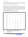
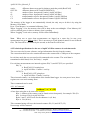
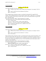
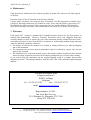
1
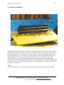
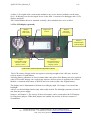
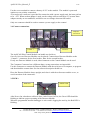
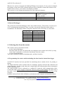
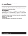
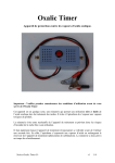
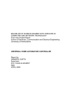
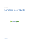
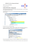
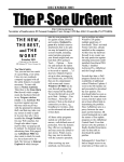
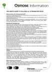
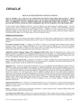
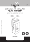
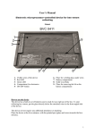
ApiSCAN-Plus_Manual_E
1/15
ApiSCAN-Plus
User Manual
Lowland Electronics bvba Langekoestalstraat 2 B-8432 Leffinge Belgium
tel.: +32 59/27.93.92 fax.: + 32 59/27.97.93 E-mail: [email protected]
URL: http://users.pandora.be/lowland
ApiSCAN-Plus_Manual_E
2/15
1. Quick reference ..................................................................................................................................................3
2. The Detector Module ..........................................................................................................................................4
3. The Control Module............................................................................................................................................5
3.1 The LCD display (optional)...........................................................................................................................6
3.2 External datalogger .......................................................................................................................................7
3.3 Power Connections .......................................................................................................................................7
3.4 Counter connections......................................................................................................................................8
3.5 LED’s...........................................................................................................................................................8
3.6 Internal Datalogger .......................................................................................................................................9
4. Collecting data from the counter .........................................................................................................................9
4.1 Programming the counter and downloading the data from the internal data logger ..........................................9
4.2 Technical specifications for the use of ApiSCAN-Plus counters in real time mode. ......................................13
4.2.1 A-Command.........................................................................................................................................13
4.2.2 B-Command.........................................................................................................................................14
4.2.3 C-Command.........................................................................................................................................14
6. Maintenance .....................................................................................................................................................15
7. Warranty...........................................................................................................................................................15
Lowland Electronics bvba Langekoestalstraat 2 B-8432 Leffinge Belgium
tel.: +32 59/27.93.92 fax.: + 32 59/27.97.93 E-mail: [email protected]
URL: http://users.pandora.be/lowland
ApiSCAN-Plus_Manual_E
3/15
1. Quick reference
ApiSCAN® is a low cost activity counter for bee colonies. It was especially developed for the
beekeeper but can also be used for experimentation and research.
Every set is provided with the following parts:
• Detector Module
• Control Module
• Power Adapter (only for European countries)
• User Manual + software
Control
Module
Detector
Module
The ApiSCAN-Plus beecounter is able to follow up two beehives. On every beehive up to two
Detector Modules can be placed. The ApiSCAN-Plus counter detects every bee that is passing
through, no distinction is made between In- and Out-going bees. The obtained amount of passes
has to be divided by two to obtain an indication of flight activity. The Control Module has in
internal datalogger, for storage of the activity results. Programming the datalogger and
downloading the data can be done by a Personal Computer.
Power Supply: 12V DC, 30 mA
Lowland Electronics bvba Langekoestalstraat 2 B-8432 Leffinge Belgium
tel.: +32 59/27.93.92 fax.: + 32 59/27.97.93 E-mail: [email protected]
URL: http://users.pandora.be/lowland
ApiSCAN-Plus_Manual_E
4/15
2. The Detector Module
Detector Module placed on a demonstration hive
The Detector Module sits safely in a weather resistant housing that can easily be fixed in front of
the hive entry. It gives access to the hive by twenty channels so as not to hinder in any way the
free movement of bees. Every time a bee enters or leaves the hive, the detector generates an
electrical impulse that is forwarded to the Control Module. This means that this detector does
not discriminate between bees entering or leaving the hive. The detector does not accept
especially slow or very rapid movements to keep the count honest, and also compensates
automatically for the outside lighting conditions. For strong colonies, two Detector Modules can
be installed on the hive entrance and connected to one Control Module. The bees can then use 40
channels to enter the hive.
Advice:
Direct sunshine has to be avoided by installing a protection cap above the Detector Module.
Lowland Electronics bvba Langekoestalstraat 2 B-8432 Leffinge Belgium
tel.: +32 59/27.93.92 fax.: + 32 59/27.97.93 E-mail: [email protected]
URL: http://users.pandora.be/lowland
ApiSCAN-Plus_Manual_E
5/15
3. The Control Module
Backup battery for
Total Counter
Display
Indicator
LED’s
Total Counter Display
(Optional)
Connection to
external datalogger
Reset Display
Jumper 3
Enable/Disable
Display Backlight
Computer
connection
(RS232)
Control Module
wall fixation hole.
Connection for
second Detector
Module of Beehive2
(Counter2)
12V DC
Power
Supply (wire
connection)
Connection for
second Detector
Module of Beehive1
(Counter1)
12V DC
Power
Supply
Connection
Connection for
second Detector
Module of Beehive1
(Counter1)
Jumpers 1-2
Connect/disconnect
Counter1 and/or
Counter2 to Display
Connection for first
Detector Module of
Beehive1
(Counter1)
Lowland Electronics bvba Langekoestalstraat 2 B-8432 Leffinge Belgium
tel.: +32 59/27.93.92 fax.: + 32 59/27.97.93 E-mail: [email protected]
URL: http://users.pandora.be/lowland
ApiSCAN-Plus_Manual_E
6/15
A short (1,5m) signal cable connects this module to one or two detector modules (on the same
hive). Its housing was also developed for use in the field. It consists of a datalogger and a LCD
display (optional).
The Control Module has to be mounted vertically, direct sunshine have to be avoided.
3.1 The LCD display (optional)
Backup
Battery for
LCD counter
9 digit LCD
Counter
RESET
button for
LCD display
Jumper 3
Enable/Disable
LCD Backlight
Jumper 1
Connect/Disconnect
Counter 1 to LCD
Display counter
Jumper 2
Connect/Disconnect
Counter 2 to LCD
Display counter
LCD Counter with associated components in detail
The LCD counter (9 digits) itself can register a count big enough to last a full year. It can be
reset by means of a push button.
A backup battery guarantees no loss of counter data when power fails. Battery has to be replaced
when LCD counter display can’t read clearly anymore when no power is applied to the Control
Module. A common used battery (CR2032) has to be used to replace the original battery.
The display can be illuminated to facilitate its reading by night. Use Jumper 3 to activate this
backlight.
Advice: use the backlight function only when really needed. The backlight consumes at least 15
mA from the power supply!
Jumper 1 and Jumper 2: The activity of the used counters can be connected to the LCD display
by using these jumpers. When both jumpers are enabled, the activity of the two counters is
accumulated.
Lowland Electronics bvba Langekoestalstraat 2 B-8432 Leffinge Belgium
tel.: +32 59/27.93.92 fax.: + 32 59/27.97.93 E-mail: [email protected]
URL: http://users.pandora.be/lowland
ApiSCAN-Plus_Manual_E
7/15
3.2 External datalogger
Counter1
TTL pulses
1 ms
Counter2
TTL pulses
1 ms
GROUND
Connections to a external datalogger
ApiSCAN-Plus delivers two signals on TTL-level. These signals (Counter1 and Counter2) can be connected to an
external datalogger or a computer with digital inputs (parallel port or other digital interface).
Specifications:
Pulse width: >1 ms
Frequency: < 1 kHz
Signal level: TTL
3.3 Power Connections
Power Supply
Adapter connector.
Central pin => +12V
+12V
Screw
Connector
Ground
Screw
Connector
Power limit specifications:
Description
Minimum Voltage
Maximum Voltage
Maximum ApiSCAN-Plus Current (1)
Maximum Backlight Current
Maximum Detector Module Current (2)
(1) Backlight disabled
(2) Not exposed to direct sunlight.
Value
9
12
10
15
15
Unit
V
V
mA
mA
mA
Lowland Electronics bvba Langekoestalstraat 2 B-8432 Leffinge Belgium
tel.: +32 59/27.93.92 fax.: + 32 59/27.97.93 E-mail: [email protected]
URL: http://users.pandora.be/lowland
ApiSCAN-Plus_Manual_E
8/15
Use the screw terminal to connect a battery of 12V to the module. The module is protected
against reverse polarity connection.
A second power connector is provided for connection with a power supply unit, the inner pin has
to be +12V. When such an adapter is used, set the voltage selector switch on 9V, because these
adapters mostly are not stabilised, and deliver an overvoltage when not full loaded.
Only one connector should be used to connect a power supply to the counter!
3.4 Counter connections
Computer
Connection
Counter 1
Counter 2
The ApiSCAN-Plus Control Module can handle two beehives.
On every hive two Detector Modules can be placed. Connect these Detector Modules to the
‘Counter 1’ connectors for the first beehive, ditto for the second beehive.
If only one Detector Module is used, either connector on the Control Module can be used.
The Computer Connector has a different shape, wrong connections are impossible.
Use this connector to connect the Detector Module with the serial port of a computer, to program
and download the counter data. See the software description further on.
Place the Detector Module always upright, and close it with the soft mousse and the cover, to
avoid corrosion of the connectors.
3.5 LED’s
RED LED
GREEN LED
After Power On, a hardware selftest is done. After Power On Test, the Green LED should be
blinking to indicate proper operating of the Detector Module.
When the programmed internal datalogger is active and is logging bee activity, the Red LED is
blinking.
Lowland Electronics bvba Langekoestalstraat 2 B-8432 Leffinge Belgium
tel.: +32 59/27.93.92 fax.: + 32 59/27.97.93 E-mail: [email protected]
URL: http://users.pandora.be/lowland
ApiSCAN-Plus_Manual_E
9/15
When no bee activity is detected, the blinking LED has a low intensity. If a bee passed a channel,
the intensity of the active LED is shortly increased. This is helpful to control the reaction of the
module to bee activity, even if there is no Display available.
This can also be seen during data transmission to the connected computer.
Power On Test sequence:
Normal operation, datalogger not active
Normal operation, datalogger active
RED +GREEN (1 second)
GREEN (1 second)
RED (1 second)
GREEN blinking
RED blinking
3.6 Internal Datalogger
The counter has an internal datalogger with a non-volatile memory. The memory can store up to
16127 periods during maximum 61 days. A period is an interval within the count results is
accumulated. The maximum number of log-days depends on the period-time, see next table.
Period Time
1
5
10
15
30
60
Maximum Log days
11
55
61
61
61
61
4. Collecting data from the counter
The counters can be used in three modes:
- use the internal datalogger
- Real time mode: the user can connect his own computer to the counter and is able, by using
some simple commands, to collect the data directly from the counter.
- use an external datalogger
These three methods can be used simultaneously, and don’t interfere.
4.1 Programming the counter and downloading the data from the internal data logger
An RS-232C interface has been provided for transferring data to another device for printing or
storage.
The output functions used to transfer data are completely separate from the data collection and
storage functions. In other words, data can be output while still collecting data with no interruption
of the collection process.
The ApiSCAN-Plus can be connected to a standard PC using the serial communication cable.
Connect this cable to the Computer Connection connector on the Control Module. The other side of
the cable (9 pins D-connector) has to be connected to the COM1 or COM2 Serial Port of the
computer.
Install the software BeeSCANv2 (Windows environment) on the computer and start this software.
Lowland Electronics bvba Langekoestalstraat 2 B-8432 Leffinge Belgium
tel.: +32 59/27.93.92 fax.: + 32 59/27.97.93 E-mail: [email protected]
URL: http://users.pandora.be/lowland
ApiSCAN-Plus_Manual_E
10/15
This can be done by running setup.exe from the CD-ROM.
This software can be used for ApiSCAN-Plus and for BeeSCAN counters.
First select the Counter Address and the used Serial Port.
For a BeeSCAN counter: the Counter Address is indicated on his front panel.
For an ApiSCAN-Plus counter: the Counter Address is always 250.
Press ‘IDENTIFY COUNTER’ to test the communication and to get some information from the
counter.
Lowland Electronics bvba Langekoestalstraat 2 B-8432 Leffinge Belgium
tel.: +32 59/27.93.92 fax.: + 32 59/27.97.93 E-mail: [email protected]
URL: http://users.pandora.be/lowland
ApiSCAN-Plus_Manual_E
11/15
When communication succeeds, the above screen can be seen. The push buttons are now available.
Press the ‘READ COUNTER’ button to get the Counter Settings from the counter. These Counter
Settings can then be changed by the computer settings, by pressing ‘PROGRAM COUNTER’.
Press the ‘Log’ button to start a logging sequence. When done, “Log On’ is green coloured.
Be sure that the Start Time and Start Date not are reached yet!
As soon a match is found between Time-Date and Start Time-Start Date, logging starts and
“Logging” is coloured green.
Lowland Electronics bvba Langekoestalstraat 2 B-8432 Leffinge Belgium
tel.: +32 59/27.93.92 fax.: + 32 59/27.97.93 E-mail: [email protected]
URL: http://users.pandora.be/lowland
ApiSCAN-Plus_Manual_E
12/15
Press ‘DUMP DATA’ to download measurement files from the counter to the computer. Next
screenshot shows the situation. Select a directory where you want the files be saved and press ‘Start
Dump’. All files will be copied from the counter to the computer.
Press ‘Cancel’ to leave this mode, and to return to the main program.
After dumping is completed, for every file in the counter, there is an ASCII-file made in the default
directory on the computer. A typical name of such an ASCII file is for example: AB271194.txt.
The first two characters are the Label that was given to the file in the counter (see Label Mode).
The Start Date of the log sequence is appended to this Label. The extension of the files is always
txt. Attention: the counternumber is not indicated in the filename, neither in the ASCII-file. Be
careful when more than one counter is dumped, avoid identical filenames! On the screen the
number of created files are indicated.
It takes only 1 minute to dump the whole memory into the computer.
A typical example of a created ASCII file is shown on the next lines:
Location : AB
Date : 300104
Number of measurements : 24
time:
out:
in:
OUT:
IN:
time
out
in
OUT
IN out-in
time
c2
c1
C2
C1
c2-c1
00:00
0
0
0
0
0
01:00
0
0
0
0
0
02:00
0
0
0
0
0
03:00
0
0
0
0
0
04:00
0
0
0
0
0
05:00
1
1
1
1
0
06:00
8
7
9
8
1
07:00
19
17
28
25
2
08:00
23
26
51
51
-3
09:00
19
9
70
60
10
10:00
5
5
75
65
0
11:00
29
33
104
98
-4
12:00
55
60
159
158
-5
13:00
33
33
192
191
0
14:00
12
13
204
204
-1
15:00
3
2
207
206
1
16:00
0
0
207
206
0
17:00
0
0
207
206
0
18:00
0
0
207
206
0
19:00
0
0
207
206
0
20:00
0
0
207
206
0
21:00
0
0
207
206
0
22:00
0
0
207
206
0
23:00
0
0
207
206
0
start time of every period ( the period time was 60 minutes)
number of bees that went out during this period (BeeSCAN)
number of bees that came back during this period (BeeSCAN)
totalled out (BeeSCAN)
totalled in (BeeSCAN)
OUT-IN
C2-C1
0
0
0
0
0
0
1
3
0
10
10
6
1
1
0
1
1
1
1
1
1
1
1
1
Lowland Electronics bvba Langekoestalstraat 2 B-8432 Leffinge Belgium
tel.: +32 59/27.93.92 fax.: + 32 59/27.97.93 E-mail: [email protected]
URL: http://users.pandora.be/lowland
ApiSCAN-Plus_Manual_E
out-in:
OUT-IN:
c1:
c2:
C1
C2:
13/15
difference between out and in, during a particular period (BeeSCAN)
difference between OUT and IN (BeeSCAN)
number of bees that passed Counter1 (ApiSCAN-Plus)
number of bees that passed Counter2 (ApiSCAN-Plus)
totalled number of bees that passed Counter1 (ApiSCAN-Plus)
totalled number of bees that passed Counter2 (ApiSCAN-Plus)
The memory of the logger in not automatically cleared, the only way to do this is by using the
Memory Clear Mode:
Press ‘Clear Memory’ to command a Memory Clear.
When “Logging” is on, the memory clear will be done at the next midnight. “Clear Memory On”
will be coloured green, to show a memory clear is pending.
When “Logging” is not active, memory will be cleared immediately.
Note: When two or more short measurements are logged on a same day, be sure every
measurement has got a different label. This is necessary to avoid identical names for two different
files. The first will be overwritten by the second, so the first file will be lost!
4.2 Technical specifications for the use of ApiSCAN-Plus counters in real time mode.
The user can write his own software, and get information directly from the counter.
The connection cable has to be connected between the counter and a COM port of the computer.
In real time mode the user can send serial commands to the counter. The serial data is
transmitted at 9600 baud, 8 bit, No Parity, 1 stopbit.
For real time measurements two internal registers IN(C1) and OUT(C2) are provided.
IN(C1):
Ø BeeSCAN: IN coming bees
Ø ApiSCAN-Plus: Counter 1 activity
OUT(C2):
Ø BeeSCAN: OUT going bees
Ø ApiSCAN-Plus: Counter 2 activity
These internal counters are independent of the internal data logger. As soon power in on, these
registers are reset and counting starts.
Three commands can be used:
4.2.1 A-Command
‘Address’,’A’,’A’,128
A four-byte string has to be sent to the counter:
Byte 1: address of the counter (can be found on his front panel), for example: 250 (FA
hex). Is always 250 for ApiSCAN-Plus
Bytes 2 and 3: ASCII code for the character A (41 hex)
Byte 4: 128 (80 hex)
This command string will reset the internal counters IN (C1) and OUT (C2)
No message will be returned.
Lowland Electronics bvba Langekoestalstraat 2 B-8432 Leffinge Belgium
tel.: +32 59/27.93.92 fax.: + 32 59/27.97.93 E-mail: [email protected]
URL: http://users.pandora.be/lowland
ApiSCAN-Plus_Manual_E
14/15
4.2.2 B-Command
‘Address’,’B’,’B’,128
A four-byte string has to be sent to the counter:
Byte 1: address of the counter (can be found on his front panel), for example: 250 (FA
hex)
Bytes 2 and 3: ASCII code for the character B (42 hex)
Byte 4: 128 (80 hex)
This command string will ask the counter to send back the internal IN(C1) and OUT(C2)
counters. This command will also reset the internal counters IN(C1) and OUT(C2). An internal
copy of the counters will be kept in memory (these copies can be downloaded once again with
the C-command string).
The counter will answer with a 15-byte long string, for example:
81h,30h,30h,30h,30h,31h,32h,30h,30h,30h,30h,30h,39h,4Ch,80h
byte 1: always 81 hex
bytes 2 to 7: IN(C1) counter (in this example 000012)
bytes 8 to 13: OUT(C2) counter (in this example 000009)
byte 14: checksum of the bytes 2 to 13, with bit 7 set to zero!
byte 15: always 80 hex
4.2.3 C-Command
‘Address’,’C’,’C’,128
A four-byte string has to be sent to the counter:
byte 1: address of the counter (can be found on his front panel), for example: 250 (FA
hex)
Bytes 2 and 3: ASCII code for the character C (43 hex)
byte 4: 128 (80 hex)
This command string will ask the counter to send back the old values of the internal IN(C1) and
OUT(C2) counters. These old values are copies of the IN(C1) and OUT(C2) counters, before
they were reset by the ‘B’ command. The ‘C’ command is only necessary when there is need to
re-ask for the counter information because there was a transmission error in the answer of the
counter on a ,B’ command.
The counter will answer with a 15-byte long string, for example:
81h,30h,30h,30h,30h,31h,32h,30h,30h,30h,30h,30h,39h,4Ch,80h
byte 1: always 81 hex
bytes 2 to 7: IN(C1) counter (in this example 000012)
bytes 8 to 13: OUT(C2) counter (in this example 000009)
byte 14: checksum of the bytes 2 to 13, with bit 7 set to zero!
byte 15: always 80 hex
Lowland Electronics bvba Langekoestalstraat 2 B-8432 Leffinge Belgium
tel.: +32 59/27.93.92 fax.: + 32 59/27.97.93 E-mail: [email protected]
URL: http://users.pandora.be/lowland
ApiSCAN-Plus_Manual_E
15/15
6. Maintenance
Only the detector module has to be cleaned regularly by means off a soft piece off cloth, dipped
in alcohol.
Function control of the 20 channels in the Detector Module:
Using a small soft plastic can easily test these 20 channels. Use this equipment to simulate a bee
passage by blocking temporarily one channel at a time. Every time the plastic is moved out off
the channel, the display counter will be incremented by one, and the blinking LED should be
more intense during a short time. Movements that are too quick or too slowly will be ignored.
7. Warranty
Each ApiSCAN® counter is warranted by Lowland Electronics bvba to be free from defects in
material and workmanship. However, Lowland Electronics bvba’s sole obligation under this
warranty shall be to repair or replace any part of the instrument which Lowland Electronics bvba’s
examination discloses to have been defective in material or workmanship without charge and only
under the following conditions, which are:
• The defects are called to the attention of Lowland, in writing within one year after the shipping
date of the instrument.
• The instrument has not been opened, maintained, repaired or altered by anyone who was not
approved by Lowland.
• The instrument was used in the normal, proper and ordinary manner and has not been abused,
altered, misused, neglected, involved in an accident or damaged by act of God or other casualty.
If you need to ship your instrument, use the original shipping carton or a package that provides
adequate protection. The package should be insured for the value of the instrument against damage
and loss.
Lowland Electronics bvba
Langekoestalstraat 2
B-8432 Leffinge
Belgium
tel.: +32-59-27.93.92
fax.: +32-59-27.97.93
email: [email protected]
Representative in USA :
Jan Aerts Bee Services
2211 Borman Av. Mesquite, TX 75150
Phone 972 270-0683
Lowland Electronics bvba Langekoestalstraat 2 B-8432 Leffinge Belgium
tel.: +32 59/27.93.92 fax.: + 32 59/27.97.93 E-mail: [email protected]
URL: http://users.pandora.be/lowland