1
BACHELOR OF SCIENCE DEGREE WITH HONOURS IN
COMPUTER AND NETWORK TECHNOLOGY
Final Year Project Report
School of Electronic, Communication and Electrical Engineering
University of Hertfordshire
UNIVERSAL HOME AUTOMATION CONTROLLER
Report by
SAMARTH GUPTA
Supervisor
Prof. TALIB ALUKAIDEY
Date
APRIL 2008
DECLARATION STATEMENT
I certify that the work submitted is my own and that any material derived or quoted from the
published or unpublished work of other persons has been duly acknowledged (ref. UPR
AS/C/6.1, Appendix I, Section 2 – Section on cheating and plagiarism)
Student Full Name: SAMARTH GUPTA
Student Registration Number: 04085055
Signed: …………………………………………………
Date: 11 April 2008
School of Electronic, Communication and Electrical Engineering
BSc Final Year Project Report
ABSTRACT
Home automation is a rapidly growing technology and the need for enhancement of such
systems is always there to shape the new digital lifestyle we live in.
The report explains the various stages of work carried out to create a universal home
automation controller using the VM110 USB interface
interface board. This report contains an
introduction to the project, home automation system and its components, the technologies
available to implement such systems, the design and development process for the project.
A final evaluation of the developed
develop
system iss done, providing the limitations of the system, it
advantages, disadvantages and the future developments possible with this project.
SAMARTH GUPTA / UNIVERSAL HOME AUTOMATION CONTROLLER
i
School of Electronic, Communication and Electrical Engineering
BSc Final Year Project Report
ACKNOWLEDGEMENTS
I would like to thank everyone who have supported me through the entire duration of this
project. I would like thank by family, friends for their support and their advice. I am grateful to my
project supervisor Prof. Talib Alukaidey for helping me throughout the duration of this project
and providing his guidance at all times.
SAMARTH GUPTA / UNIVERSAL HOME AUTOMATION CONTROLLER
ii
School of Electronic, Communication and Electrical Engineering
BSc Final Year Project Report
TABLE OF CONTENTS
DECLARATION STATEMENT ................................................................................................
........................................i
ABSTRACT ................................................................................................................................
................................
.....................................i
ACKNOWLEDGEMENTS ................................................................................................
.............................................. ii
TABLE OF CONTENTS ................................................................................................
................................
................................................ iii
LIST OF FIGURES ................................................................................................
................................
.........................................................v
GLOSSARY ................................................................................................................................
................................
................................... vi
1.
2.
INTRODUCTION ................................................................................................
................................
.................................................. 1
1.1
Overview................................
................................................................................................
........................................................ 1
1.2
Aim ................................................................................................................................
................................
................................ 2
1.3
Objectives ................................................................................................
................................
...................................................... 2
1.4
Feasibility ................................................................................................
................................
...................................................... 3
1.4.1
Technical ................................................................................................
................................
............................................... 3
1.4.2
Economical ................................................................................................
............................................ 3
1.4.3
Schedule................................
................................................................................................
................................................ 3
1.4.4
Operational ................................................................................................
............................................ 3
1.4.5
Legal ................................................................................................
................................
...................................................... 4
1.5
Report Structure ................................................................................................
............................................ 4
1.6
Chapter Summary ................................................................................................
......................................... 5
BACKGROUND RESEARCH ................................................................
............................................................... 6
2.1
2.1.1
History ................................................................................................
................................
................................................... 6
2.1.2
Standards and Bridges ................................................................
.......................................................... 7
2.1.3
Elements................................................................................................
................................
................................................ 8
2.1.4
Architecture ................................................................................................
........................................... 9
2.2
3.
User Requirements
rements ................................................................................................
....................................... 9
2.2.1
Questionnaire and Interviews ................................................................
................................................ 9
2.2.2
Case Study ................................................................................................
.......................................... 11
2.3
Interface Board ................................................................................................
................................
............................................ 12
2.4
Chapter Summary ................................................................................................
....................................... 13
System Design................................
................................................................................................
.................................................... 14
3.1
System Structure ................................................................................................
......................................... 14
3.2
System Components ................................................................................................
................................... 15
3.2.1
Device
ce Driver ................................................................................................
....................................... 15
3.2.2
Control Application ..............................................................................................
.............................. 15
3.2.3
Web Application ................................................................................................
.................................. 16
3.3
4.
Home Automation Systems ................................................................
........................................................... 6
Chapter Summary ................................................................................................
....................................... 16
Development................................
................................................................................................
....................................................... 17
SAMARTH GUPTA / UNIVERSAL HOME AUTOMATION CONTROLLER
iii
School of Electronic, Communication and Electrical Engineering
5.
6.
BSc Final Year Project Report
Testing ................................................................................................................................
................................
................................ 31
5.1
White Box Testing ................................................................................................
....................................... 31
5.2
Black Box Testing ................................................................................................
........................................ 31
5.3
Evaluation ................................................................................................
................................
.................................................... 31
Conclusion ................................................................................................
................................
.......................................................... 32
6.1
Future Developments:................................................................................................
Developments:
.................................... 32
REFERENCES ................................................................................................
................................
............................................................ 33
BIBLIOGRAPHY................................................................................................
................................
.......................................................... 34
APPENDICES ................................................................................................
................................
............................................................. 35
SAMARTH GUPTA / UNIVERSAL HOME AUTOMATION CONTROLLER
iv
School of Electronic, Communication and Electrical Engineering
BSc Final Year Project Report
LIST OF FIGURES
Figure 1 Universal Home Automation Control ................................................................
.............................................. 1
Figure 2 Web Interface of Indigo Home Automation System ......................................................
................................
11
Figure 3 USB Interface Board (VM110) - Inputs and Outputs ....................................................
................................
12
Figure 4 USB Interface Board (VM110) - Components ..............................................................
.............................. 12
Figure 5 Block diagram of the system structure ................................................................
.......................................... 14
SAMARTH GUPTA / UNIVERSAL HOME AUTOMATION CONTROLLER
v
School of Electronic, Communication and Electrical Engineering
BSc Final Year Project Report
GLOSSARY
AC
Alternating Current
ASP
Active Server Pages
BSR
British Sound Reproduction
CCTV
Closed Circuit Television
CEBUS
Consumer Electronics Bus
DLL
Dynamic Link Library
EIA
Electronic Industries Association
HVAC
Heating, Ventilating and Air Conditioning
RF
Radio Frequency
PLC
Power Line Control
UPB
Universal Powerline Bus
UniHAC
Universal Home Automation Controller
UPnP
Universal Plug and Play
SAMARTH GUPTA / UNIVERSAL HOME AUTOMATION CONTROLLER
vi
School of Electronic, Communication and Electrical Engineering
BSc Final Year Project Report
1. INTRODUCTION
Home automation is a rapidly progressing and maturing modern technology which will soon
be an essential part of our digital lifestyle; be it for security, convenience, energy-saving
energy
or
other reasons.
1.1
Overview
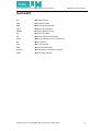
The purpose of this report is to present a comprehensive and concise description of all the
phases through the lifecycle of my final year project ‘Universal Home Automation Controller’ a program to enable automatic and controlled management
management of intelligent homes integrated
with various types of sensors, switches, alarms, lights and motion capture cameras that work
in a collaborative manner when connected to a interface board or directly to a host system
running this program, which can be
be accessed from the host system, ubiquitous devices within
a networked home and remotely from anywhere in the world using services provided over
communication channels like internet, cellular and telephone networks.
Figure 1 Universal
iversal Home Automation Control
During the development, testing and demonstration of this project, a USB experimental
interface board (known as VM110 or K8055), designed and developed by Velleman
Components N.V. based in Belgium, was used as a key resource to simulate the variety of
components
onents present in a digital home such as temperature and motion sensors, dimmers,
switches, lights, etc. which can be conceptually represented by the analogue and digital,
inputs and outputs provided on this interface board. The technical and functional details
de
of
this interface board with reference to its requirement and usage in this project have been
discussed throughout the report.
SAMARTH GUPTA / UNIVERSAL HOME AUTOMATION CONTROLLER
1
School of Electronic, Communication and Electrical Engineering
BSc Final Year Project Report
Further in this chapter the aim, objectives and initial feasibility aspects of the project are
discussed together with a brief
ief about the feasibility aspects considered at the beginning of the
project to achieve its objectives and lastly, the structure of the report with an overview on the
organization and contents of each chapter included in this report.
1.2
Aim
The aim of this project was to design and develop a software system to control and manage
lighting, climate and security features within a typical domestic environment, using the VM110
interface board and provide access to these features via graphical user interface that can be
accessed via networked devices, within the home as well as remotely, using a standard web
browser.
1.3
Objectives
To achieve the aim set for this project, the following objectives were pursued for successful
completion the project:
•
The design of a three tier software system that integrates with the USB interface
board provided as the platform for simulating the basic features in an automated
home environment and provides all the necessary functionalities.
•
Development of a Dynamic Link Library (DLL) as a wrapper to access the
communication routines which control the analogue and digital, inputs and
outputs of the USB interface board.
•
Control application design and development
developmen as the middle-tier
tier between the
wrapper DLL and the user interface (web application).
•
Creation of a user interface (web application) as the top-tier
top tier of the system
architecture providing access to the users to the features supported by the
control application.
tion.
•
Integration of addition features like live video stream and motion detection using
camera(s) installed within the house and speech announcements and notification
when certain events occur.
•
Testing, optimization and enhancement of the system.
SAMARTH GUPTA / UNIVERSAL HOME AUTOMATION CONTROLLER
2
School of Electronic, Communication and Electrical Engineering
1.4
BSc Final Year Project Report
Feasibility
A feasibility study was carried out at the beginning of this project and the following is a brief
analysis of it under five interrelated types:
1.4.1 Technical
From a technical point of view, this project was highly feasible because the technical
resources required for the development of this project were already available from the
university which includes integrated development environment (IDE) such as Microsoft Visual
Studio 2005/2008, USB interface board (VM110) and a USB web camera. Lack of prior
experience and knowledge of the development platform used would have been a limitation
but my previous experience in similar programming languages/technologies
languages/technologies was a motivation
use the Microsoft .NET platform for the development of this project.
1.4.2 Economical
The maximum available budget for this project was £50 (fifty pounds only), which was more
than sufficient as the only cost that would be incurred was to purchase the USB interface
board (VM110) but it was issued on loan from the university’s final year project’s lab store for
the duration of this project. For information only the approximate market value of this interface
board is £30 only. All the other hardware and software requirements were already available in
the university for by all the students studying in the faculty of engineering and information
sciences at no cost.
1.4.3 Schedule
To manage the workflow of the project efficiently and for its successful
ccessful on time completion
certain milestones were set at the beginning of the project with predefined timescales for the
design, development, testing and documentation of all the stages involved during the lifecycle
of this project. Based on this provisional
provisional project plan a Gantt chart was produced initially (see
Appendix A) to outline the sequence and approximate duration of each project stage.
1.4.4 Operational
Evaluation of the operational feasibility of this project was a key factor in deciding the
methodologies
ogies used in design, development and deployment of this project for it to work in a
given environment. After the preliminary research, various proactive measures were devised
in case certain elements in the initial system design were non-functional
non functional then they
t
could be
SAMARTH GUPTA / UNIVERSAL HOME AUTOMATION CONTROLLER
3
School of Electronic, Communication and Electrical Engineering
BSc Final Year Project Report
re-worked
worked upon or replaced with tried and test solutions, depending on the time constraints,
which are shown in the project
projec workflow chart (see Appendix B).
1.4.5 Legal
The legal aspects of this project are very limited as this is an academic project
proje with a lifespan
of one academic year only but nonetheless it has been taken into account that during the
course of this project any private and confidential data about a person or organization will not
be stored or used in an inappropriate manner. The university’s
university’s codes of practice for the use of
human volunteers, risk and ethics have been strictly followed. Any material derived or quoted
from the published or unpublished work of other persons has been duly acknowledged.
1.5
Report Structure
This report consists of the following six chapters, each of which provides a thorough and
concise account of the work undertaken and learning outcomes from various stages of this
project:
•
Introduction This is the current chapter in which an overview to home
h
Chapter 1 - Introduction:
automation systems and the USB interface board (VM110), is provided together with
the aim and objectives of this project. It also includes the highlights from the initial
feasibility study for this project and an insight to the contents of this report.
•
Chapter 2 - Background Research: The next chapter in this report is a detailed
description and analysis of the research conducted to understand the need of home
automation systems and the user requirements for everyday use of such systems in
their residences.
•
Chapter 3 - Design:
Design In this chapter a set of solutions are suggested to develop a
complete application to implement a ‘Universal Home Automation Controller’ and then
the most suitable approach is selected for the development of this project after
analyzing
alyzing various aspects related to each of these solutions.
•
Chapter 4 - Development:
Development The complete development process of this project is
described in this chapter with prominence to the methodology used, achievements
and downfalls during this phase of the project.
•
Chapter 5 - Testing:
Testing This chapter is a synopsis of the types testing carried out to
confirm that developed system was working as required under a range of operational
conditions and the debugging done to overcome the difficulties noticed.
SAMARTH GUPTA / UNIVERSAL HOME AUTOMATION CONTROLLER
4
School of Electronic, Communication and Electrical Engineering
•
BSc Final Year Project Report
Chapter 6 - Conclusion:
Conclusion Finally, in this last chapter a concise summary of the
complete project and this report is provided with reference of the initial aim and
objectives of this project. Any future developments to this project and its commercial
viability are also included here.
1.6
Chapter Summary
This chapter introduced the concept of home automation in relationship with this project, its
aim and objectives. It also includes a review of the key aspects determining the feasibility of
this project which was carried out at the beginning of the project and an insight into the
contents of the remaining chapters of this report.
SAMARTH GUPTA / UNIVERSAL HOME AUTOMATION CONTROLLER
5
School of Electronic, Communication and Electrical Engineering
BSc Final Year Project Report
2. BACKGROUND RESEARCH
The essence of any home automation system is to provide innovative and effective ways for
controlling and monitoring appliances within intelligent homes. This chapter is based on the
research and investigation conducted about the history of home automation systems,
systems existing
standards and controllers used for home automation, the user requirements
requireme
from such
systems and the available technologies to fulfil them. In doing so comparisons were made
and the most suitable approaches
approach were chosen for the design and development this project.
2.1
Home Automatio
utomation Systems
Home automation iss a branch of building automation,, specializing in the specific automation
requirements for domestic environment and thus it also sometimes known as domotics,
derived from the words domus (Latin for house) and robotics automation.
2.1.1 History
The timeline for home automation
automati starts from the mid-1970s, when a group of engineers who
owned a company called Pico Electronics based in Glenrothes, Scotland developed an
automatic record changer called Accutrac, in partnership with BSR (British Sound
Reproduction), which was controlled
controlled by a remote control that used ultrasonic signals.
The features of Accutrac inspired the company’s next project, using remote control for
appliances and lights. This concept used AC (Alternating Current) wiring for transmitting
signals to control lightss and appliances and they
hey named this project as ‘X10’ because it was
the tenth project that they had worked on. After refining this new technology for few years,
X10 products began to appear in stores. Pico Electronics in partnership with BSR formed X10
Ltd
d and the BSR System X10 was born. This system consisted of 16 channel command
console, a lamp module and an appliance module. Later additions to the system included a
wall switch module and the first X10 timer, giving it a new name X10 Powerhouse System.
In early 1980s, X10’s first official computer interface was developed for the Mattel’s shortshort
lived Aquarius computer, which was later morphed into the Radio Shack Colour computer
interface and then into X10’s long lived CP-290
CP 290 unit, which was replaced by the ActiveHome
controller in late 1990s. Many official and shareware software were developed for the CP-290
CP
which
hich could be used with Apple IIs, Macs, DOS and Windows.
Over the years, many other standards for home automation have been developed but this
technology
chnology usually attracts either computer experts or the wealthy owing to diverse reasons.
SAMARTH GUPTA / UNIVERSAL HOME AUTOMATION CONTROLLER
6
School of Electronic, Communication and Electrical Engineering
BSc Final Year Project Report
2.1.2 Standards and Bridges
Home automation systems are built to support specific standards (protocols) for the purpose
of communicating with and controlling appliances within
thin the home. The choice of standard
depends on the type of system and appliances being used, the transmission medium, speed
and distance required, regional location of system installation and many other factors. The
type of standard being used also affects
ts the system cost, reliability and expansion options.
Home automation standards
tandards are divided into two main categories, as following:
following
•
Common Standards
These standards
tandards allow for control of most applications within
within a domestic environment
and can be implemented in a system comprising of controllers and applications that
support the specific standard. Some common standards are discussed below:
o
X10 – This standard is used by the simplest and least expensive home
automation systems.
systems The X10 compatible modules need only to be plugged
into any standard wall outlet and programmed to match the code of the other
X10 compatible devices in the house. Each module is designed to control
con
a
specific appliance only. Components using X10 standard don’
n’t share memory
and are sensitive to home wiring line noise.
o
CEBus – The CEBus (Consumer Electronics Bus) standard also known as
EIA-600 was developed by the Electronic Industries Association (EIA). It is a
set of electrical standards and communication protocols for electronic
elec
devices
to transmit
mit commands and data. This standard is media-independent
media independent, so it
can send signals over power lines, coaxial cable and unshielded twisted pair
(UTP) cable. Being a proprietary standard, it tends to be expensive to
implement because of the license fees incurred to manufactures.
o
LonWorks – This standard is built on a protocol called Echelon, developed
by Echelon
elon Corporation. This is also a media-independent
media independent standard and is
popular for automation of various common functions within houses such as
lighting and HVAC (Heating, Ventilating and Air Conditioning).
o
INSTEON – It is a dual-band mesh-topology
topology standard using both AC power
lines and radio frequency (RF) to control and communicate with electronic
devices and appliances within the home. All devices supporting this
th standard
act as peers,
peers meaning each device can transmit, receive and repeat any
message of this protocol, without requiring a master controller and network
supervision, which eliminates the need of complex network controllers
controll
and
routing tables.
SAMARTH GUPTA / UNIVERSAL HOME AUTOMATION CONTROLLER
7
School of Electronic, Communication and Electrical Engineering
o
BSc Final Year Project Report
Smart House – This is one of the latest and most sophisticated standards. It
integrates a unique wiring system and computer chip language which
enables common home appliances to communicate with each other and work
wo
together. Special
pecial Smart House compatible devices must to be used with
home automation system supporting this standard.
Other common standards are C-BUS, KNX, PLC (Power Line Control) BUS,
B
System
Box, Universal Powerline
Powerline Bus (UPB), UPnP (Universal Plug and Play).
•
Open Standards
Many home automation systems use custom-build
custom
open standards for communication
with and control of devices using a preferred controller.. Such standards are designed
in accordance with accepted standards in use in the computer industry and easily
able to integrate with other applications and devices. This substantially reduces the
total cost of development and ownership.
ownership
Bridges are used to translate communication and control information from one standard
(protocol) to another (e.g. from X10 to INSTEON).
IN
2.1.3 Elements
A home automation system is formed mainly of the following three elements:
•
Controllers – Also known as Programmable Logic Controllers (PLCs) is a digital
computer used for automation
automation of processes (tasks) and is designed for multiple digital
digi
and analogue input and output arrangements, extended temperatures ranges,
protection from electrical noise and resistance to vibration and impact. Such
controllers are real-time
time systems as output results must be performed in response to
input events within
thin a restricted time; otherwise the system’s reliability is at risk.
•
Sensors – It is a device which measures a physical magnitude and converts it into a
signal (usually electrical) which can be read by another device. Sensors can be of
many types such as
a thermal, electromagnetic, mechanical, chemical, optical,
acoustic, etc. For example,
example a thermal sensor can be used as temperature sensor to
measure the temperature of the environment around it and convert the result into a
digital signal.
•
Actuators – An actuator is a mechanical device for moving or controlling a
mechanism or system. For example,
example an electric motor, which converts electricity into
mechanical motion, can be used to automatically open and close the window shades.
SAMARTH GUPTA / UNIVERSAL HOME AUTOMATION CONTROLLER
8
School of Electronic, Communication and Electrical Engineering
BSc Final Year Project Report
2.1.4 Architecture
The design architecture
tecture of a home automation system depends mainly on the specific user
requirements and installation the environment.
environment The intelligence of a home automation system
resides in the type of architecture implemented,, which can be any one of the following three:
three
•
Centralized Architecture – This type of architecture supports a centralized
controller, which receives information from multiple sensors (inputs) and the user and
once processed, generates the appropriate instructions for the actuators (outputs).
•
Distributed Architecture – The system intelligence is disseminated among all the
components of the system that are the controllers, sensors or actuators. This is
typical of the systems of wiring in bus.
•
Mixed Architecture – Such systems comprise of features
es from both the above
mentioned types of architecture and they have several small devices (mini(mini
controllers) that are able to obtain and process information of multiple sensors and
then transmit them to the rest of the devices spread throughout the house.
2.2
User Requirements
Expectations of home automation capabilities are changing, but nothing is more important
than the human interface be it in the form of a remote, touch-panel,
panel, wall controller or web
interface. It can make or break a system's reputation. The home automation systems
therefore face a challenge, to provide more sophisticated operation, through a robust and
user friendly interface. The end users demands are changing and they need a reliable, cost
effective home automation system with an easy-to-navigate, simple-to
to-use graphical
interface.
2.2.1 Questionnaire and Interviews
In order to understand the needs of the prospective users of home automation systems, it
was important to perform a survey, which would provide a clear perceptive to the design
requirements for the user interface of this system.
A template for this questionnaire was designed with some objective questions concerned with
the layout, navigation, privacy
rivacy and security issues within a domestic environment for a typical
user (see Appendix C). Every candidate was interviewed for about five minutes to understand
their views on and expectations from home automation systems, which would be ideal for
absorption in the digital lifestyle they live. Based on the results obtained after the analyses of
SAMARTH GUPTA / UNIVERSAL HOME AUTOMATION CONTROLLER
9
School of Electronic, Communication and Electrical Engineering
BSc Final Year Project Report
this questionnaire and interviews (see Appendix C), the following were the suggestions for an
ideal home automation system and its user interface:
•
The navigation and layout of the interface should be very simple and easy to
understand for new user to the system.
system
•
The design of the
e web interface should be clear, clutter free and very responsive,
responsive
providing all the information on one (main) page only.
•
The current status of all the appliances in the house should be updated at least once
a minute and immediately for time critical services such alarms, etc.
•
Live video stream from a camera(s) installed in the house would be an ideal feature
but access video output from some camera(s) should be restricted to specific
members of the family only.
•
Software based motion detection using output from specific cameras within the house
was acceptable but sensor based motion detection was also equally preferred.
•
Speech
h announcements was an acceptable option but only if this feature can be
turned on or off depending on the user profile settings or completely for the whole
system.
•
Presence detection by tracking individual member’s mobile phone was not acceptable
by the some candidates as they leave their mobile at home sometime when going
out.
•
Receiving security alerts from the system via text message service on mobile phones
was an acceptable feature but the reliability of this service was a concern.
•
It was acceptable to record the events occurring,
occurring within the automated house and the
communication between the appliances and the home automation controller, in a
database and log files could be archived for later references.
•
It was a general opinion that the system would work ideally if a manual override for
each feature was available in case of any system breakdown or maintenance.
•
Cost of the complete system including installation and integration within the existing
environment was a concern and a system with minimal overheads
overheads was preferred.
SAMARTH GUPTA / UNIVERSAL HOME AUTOMATION CONTROLLER
10
School of Electronic, Communication and Electrical Engineering
BSc Final Year Project Report
2.2.2 Case Study
A case study was carried out while the background research for this project was in progress
and before the actual design and development phase was started. It was an
a advantageous
step to review a current system and then decide
d
the best suitable methodologies and
technologies to use in this project.
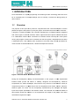
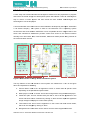
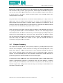
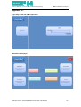
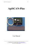
A home automation and control server named ‘INDIGO’ developed by Perceptive Automation
a US based company. This system is built for the Macintosh OS X operating system
environment and works with the INSTEON or X10 compatible devices. Indigo’s built-in
built
web
server and client/server architecture provides control and access to the control interface
remotely from other Macs, PCs, internet tablets, PDAs and mobile phones using internet as
the communication channel.
4
1
2
3
5
Figure 2 Web Interface of Indigo Home Automation System
The key features of the web interface of this system are marked from 1 to 5 in the figure
above and explained as following:
1. Current Mode: used to turn all appliances on/off or switch them to specific mode
depending on the pre-defined
pre
system states.
2. Music player controls:
ontrols: to set the volume and change tracks using the selected player.
3. Visual floor plan: A touch sensitive floor plan with a view of all the appliances in the
house and these can be controlled
control
by clicking on them and the respective appliance
image changes to display its current status (on/off).
4. Text based menu:: List of all the appliances in the house and their current status,
which can be changed by clicking on them.
5. Navigation links: These links can be used to view the other supported functions.
SAMARTH GUPTA / UNIVERSAL HOME AUTOMATION CONTROLLER
11
School of Electronic, Communication and Electrical Engineering
2.3
BSc Final Year Project Report
Interface
nterface Board
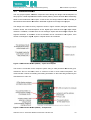
The only project specific hardware component used during the design and development of
this project is a USB experimental interface board (VM110),, which has been discussed briefly
brief
earlier in the introduction of this report. In this section, the design features and functionality of
this interface board will be described in detail with regards to its usage in this
is project.
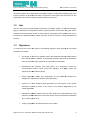
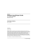
The design of the VM110 is very simple as shown in Figure 3 below,, being an experimental
interface board, the board comprises
comprise of five digital input channels and eight digital output
channels. In addition, to these there are two analogue inputs and two analogue outputs with
eight bit resolution. A maximum of four such boards can be connected to one system, if the
number of analogue or digital, inputs or outputs need to be increased.
Figure 3 USB Interface Board (VM110) - Inputs and Outputs
The board is connected to the computer system using a USB (Universal Serial Bus) port,
marked as SK7 on the board, which is common to find in most modern computers.
c
The
communication routines for reading and writing information to the board are provided by the
manufacturer in a DLL file.
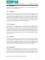
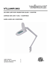
Figure 4 USB Interface Board (VM110) - Components
SAMARTH GUPTA / UNIVERSAL HOME AUTOMATION CONTROLLER
12
School of Electronic, Communication and Electrical Engineering
BSc Final Year Project Report
The components of the interface board are shown
sh
in Figure
gure 4 on the previous page, which
include a set of eight LEDs, labelled LD1 to LD8,
8, represent the status of the digital outputs
that can either be ON (1) or OFF (0) at a given time, simulate lights and alarms in this project.
projec
The next set of two LEDs, labelled LD9 and LD10,, are the analogue outputs, which imitate to
be climate controls of the house - heating and boiler system, as the analogue output value
changes between 0 and 255.
255
Five push buttons on the other side on the interface board,, labelled Inp1 to Inp5, are a set of
digital inputs used as manual control switched in the house. The two potentiometers (a
tapped resistor that can be used as a voltage divider),
divider), marked as ATT1 and ATT2, can be
used as the analogue inputs in absence of actual sensors to reproduce the output generated
by a thermostat or a manual rotary temperature setter in houses.
Other components include a set of jumpers (SK5 and SK6) to set the address of the board (0
to 3) using all possible open or close
cl
combinations of the two. Two other single jumpers,
marked SK2 and SK3, are used to control the key in for two analogue inputs respectively from
either the two potentiometers (ATT1 and ATT2), when SK2 and SK3 are closed or directly
from the two analogue input ports marked A1 and A2 on the board, when SK2 and SK3 are in
open state. Lastly, the power LED, marked as LD11, lights up whenever the board is
connected to the system and is in ON state.
2.4
Chapter Summary
This chapter sets the background, for the upcoming chapters,, by providing an insight into the
research and investigation, carried out before the design and development phase of the
project were started. It includes a brief history of home automation systems,
ystems, the need for
them, various standards, bridges
b
and elements used of implementing home automation
systems. The three different types of home automation architectures are also discussed to
provide an approach for the most suitable one to use in this project.
An analysis of the user requirements
equirements, from a home automation system, is also created by the
method of questionnaires, interview of prospective users and case study of an existing
system. Finally, technical backdrop of the interface board (VM110) used in this project to
simulate a digital home setting is also studied to design and develop the most suitable home
automation controller using it.
SAMARTH GUPTA / UNIVERSAL HOME AUTOMATION CONTROLLER
13
School of Electronic, Communication and Electrical Engineering
BSc Final Year Project Report
3. System Design
The most important factor to consider when designing a home automation controller is
intrinsic reliability. Another important
important issue is the speed with which the controller can deal with
the requests from the user as well as the appliances. A system that has a task specific
integration of components and/or sub-components
sub
will help ensure that intrinsic reliability,
communication
tion speed and compatibility with third party devices and add-ons
add ons is maintained.
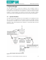
3.1
System Structure
The system structure plays a significant role in easy integration of its components
component with each
other. Thus, based on the findings from the background research
research for this subject it would be
most appropriate to implement a three tier (component) based centralized home automation
architecture, using custom developed open standards for communication with the VM110
USB interface board.
Figure 5 Block diagram of the system structure
SAMARTH GUPTA / UNIVERSAL HOME AUTOMATION CONTROLLER
14
School of Electronic, Communication and Electrical Engineering
BSc Final Year Project Report
As mentioned earlier and shown in Figure
Fi
5 on the previous page, the system can be divided
into three components, which are as following:
•
Device (Interface Board) Driver/ Communication Routine Library,
•
Control Application or the ‘Controller’,
‘Controller’ and
•
Web Application generating the Web/User Interface.
3.2
System Components
This section describes the
he design methodology and technologies present to develop and
integrate each of the three main components of system and their individual sub-components.
sub
3.2.1 Device Driver
The device driver for the USB interface board is the base communication library file known as
Dynamic Link Library (DLL) file that contains the communication routines for controlling the
VM110 (K8055) interface board. Such driver DLL files are developed in low-level
programming languages such as C/C++ and are also called unmanaged libraries.
Generally, a DLL wrapper class/program is written in higher-level
higher level programming language
lan
like
Java, C#, Visual Basic, etc. which interacts with the communication routines in the driver
(unmanaged) DLL file and the DLL wrappers can be converted into class libraries generating
a DLL file which are referred to as managed DLL.
3.2.2 Control Application
lication
The control application or the ‘controller’ is the backbone of
of the home automation system,
which acts as the transparent link between the user interface and the interface device
connecting the household appliances and other system enhancements.
A high level programming language such as Java, C#, Visual Basic, Perl, et al can be used to
develop such middleware applications. The controller uses a database if system settings,
user information and device states need to be stored for control and logging
logging purposes.
SAMARTH GUPTA / UNIVERSAL HOME AUTOMATION CONTROLLER
15
School of Electronic, Communication and Electrical Engineering
BSc Final Year Project Report
3.2.3 Web Application
The web application is the user interface (front-end)
(front end) generator to provide human interaction
with the control application (controller) over the web or in a networked home.
home A web
application is not a static web site, it is a program
program that runs on a web server and processes
information to generates dynamic web pages (or websites) which are loaded on the client
terminal and communicate to the program on the remote web server using web services,
services
supported by the web application, that provide real-time
time (dynamic) exchange and updating of
information at both ends (client and server).
Web
eb (user) interface layouts (see Appendix D) were created initially,, to support various
devices of different form factors, extracting the results from the
e user requirements
requirement analysis
performed
formed earlier for this project (see Appendix C).
3.3
Chapter Summary
The system design concepts for a home automation controller have been discussed in this
chapter. System design being an important phase during the development of this project, the
system structure and components have been chosen carefully, to enable easy development
d
and integration of each of component with the other, which are the device driver/library, the
control application (the controller) and the web application (user interface).
interface) The control
application being the middle--layer is bound by the device driver DLL wrapper at the base-level
and the web application (user interface) as the top-level
top
access layer.
SAMARTH GUPTA / UNIVERSAL HOME AUTOMATION CONTROLLER
16
School of Electronic, Communication and Electrical Engineering
BSc Final Year Project Report
4. Development
This chapter of the report describes the implementation of the main methods in the control
application, which are an enhancement to the communication routines provided by the DLL
wrapper
General methods
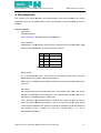
1. OpenDevice
Declaration Syntax:
public static extern int OpenDevice(int CardAddress);
Input Parameter:
CardAddress - Value between 0 and 3 which corresponds to the jumper (SK5, SK6)
setting on the K8055 board, as shown in Table 1.0 below.
SK5
SK6
Card Address
ON
ON
0
OFF
ON
1
ON
OFF
2
OFF
OFF
3
Table 1 Jumper SK5, SK6 Settings
Return Result:
int - If succeeded the return value will be the card address read of the connected
K8055 device as an integer value between 0 and 3.
Return value -1
1 indicates that a K8055 card
card with the corresponding card address was
not found.
Description:
This method opens the communication link to the K8055 card. Loads the drivers
needed to communicate via the USB port. This method should be called before any
attempts to communicate with the
t K8055 card.
As an alternate to the SetCurrentDevice method, this method can also be used to
select the active K8055 card (between 0 and 3) to read and write the data. All the
communication calls after this method is invoked are addressed to the selected card
until another card is selected by using this method again or a call to
SetCurrentDevice method.
SAMARTH GUPTA / UNIVERSAL HOME AUTOMATION CONTROLLER
17
School of Electronic, Communication and Electrical Engineering
BSc Final Year Project Report
Implementation:
private int cardConnected;
public int openDevice()
{
cardConnected = DeviceLibrary.OpenDevice(cardAddress);
return cardConnected;
}
2. CloseDevice
Declaration Syntax:
public static extern void CloseDevice();
Input Parameter: none
Return Result: none
Description:
A call to this method unloads the communication routines for the K8055 card and
unloads the driver needed to communicate via the USB port. This should usually be
the last action performed by the application program before system termination.
Implementation:
public void closeDevice()
{
DeviceLibrary.CloseDevice();
}
3. Version
Declaration Syntax:
public static extern void Version();
Input Parameter: none
Return Result: none
Description:
This method can be used to query the current version of the DLL being used. On
calling this method a message box is displayed with the relevant information.
SAMARTH GUPTA / UNIVERSAL HOME AUTOMATION CONTROLLER
18
School of Electronic, Communication and Electrical Engineering
BSc Final Year Project Report
Implementation:
public void version()
{
DeviceLibrary.Version();
}
4. SearchDevices
Declaration Syntax:
public static extern int SearchDevices();
Input Parameter: none
Return Result:
int - If succeeded the return a four bit value indicating which boards are present.
Description:
Implementation:
private int cardsConnected;
Connected;
public int searchDevices()
{
cardsConnected = DeviceLibrary.SearchDevices();
return cardsConnected;
}
5. SetCurrentDevice
Declaration Syntax:
public static extern int SetCurrentDevice(int CardAddress);
Input Parameter:
CardAddress - Value between 0 and 3 which corresponds to the jumper (SK5, SK6)
setting on the K8055
8055 board which needs to be set as the current active device for
communication.
Return Result:
int - If succeeded the return value will be the card address read of the connected
K8055 device as an integer value between 0 and 3.
Return value -1
1 indicates that a K8055 card with the corresponding card address was
not found.
SAMARTH GUPTA / UNIVERSAL HOME AUTOMATION CONTROLLER
19
School of Electronic, Communication and Electrical Engineering
BSc Final Year Project Report
Description:
This method should be preferably used to select an active K8055 card (between 0
and 3) to read and write the data. All the communication calls after this method is
invoked are addressed to the selected card until another card is selected by using
this method again or a call to OpenDevice method.
Implementation:
private int currentCard;
currentCard
public int setCurrentDevice()
{
currentCard = DeviceLibrary.SetCurrentDevice(cardAddress);
return currentCard;
}
Analogue to Digital converter methods
6. ReadAnalogChannel
Declaration Syntax:
public static extern int ReadAnalogChannel(int Channel);
Input Parameter:
Channel - Integer value of 1 or 2 which corresponds to the AD channel whose current
status is to be read.
Return Result:
int - The corresponding value of the Analogue to Digital Converter data that is read
from the board.
Description:
The input
ut voltage of the selected 8-bit
8 bit Analogue to Digital Converter channel is
converted to a value which lies between 0 and 255.
Implementation:
private int[]
[] analogInput = new int[3];
public int readAnalogIn(int AI_Nr)
{
analogInput[AI_Nr] = DeviceLibrary.ReadAnalogChannel(AI_Nr);
DeviceLibrary.ReadAnalogChannel(AI_Nr);
return analogInput[AI_Nr];
}
SAMARTH GUPTA / UNIVERSAL HOME AUTOMATION CONTROLLER
20
School of Electronic, Communication and Electrical Engineering
BSc Final Year Project Report
7. ReadAllAnalog
Declaration Syntax:
public static extern void ReadAllAnalog(ref int Data1, ref int Data2);
Input Parameters:
Data1 and Data2 - Pointers to the integer variables where the data read will be
stored.
Return Result: none
Description:
The status of both the Analogue to Digital Converters is read using this method and
stored to an array of integer variables.
Implementation:
private int[]
[] analogInput = new int[3];
public void readAllAnalogIns()
{
DeviceLibrary.ReadAllAnalog(ref analogInput[1], ref analogInput[2]);
}
Digital to Analogue conversion methods
8. OutputAnalogChannel
Declaration Syntax:
public static extern void OutputAnalogChannel(int Channel, int Data);;
Input Parameters:
Channel - Value between 1 and 2 which corresponds to the 8-bit
8 bit DA channel number
whose data is to be set to a new value.
Data - Value between 0 to 255, which is to be sent to the 8-bit
8 bit Digital to Analogue
Converter.
Return Result: none.
Description:
The indicated 8-bit
bit Digital to Analogue Converter channel is altered according to the
new data. This means the data corresponds to a specific voltage. The value 0
corresponds to a minimum output voltage (0 Volt) and the value 255 corresponds to a
maximum output voltage (+5 Volts). A value of ‘Data’ lying in between these extremes
can be translated by the following formula:
Data / 255 x 5V.
SAMARTH GUPTA / UNIVERSAL HOME AUTOMATION CONTROLLER
21
School of Electronic, Communication and Electrical Engineering
BSc Final Year Project Report
Implementation:
private int[]
[] analogOutput = new int[3];
public void changeAnalogOut(int analogOutNumber, int newAnalogOut)
{
DeviceLibrary.OutputAnalogChannel(analogOutNumber, newAnalogOut);
analogOutput[analogOutNumber] = newAnalogOut;
}
9. OutputAllAnalog
Declaration Syntax:
public static extern void OutputAllAnalog(int Data1, int Data2);
Input Parameters:
8
Digital to
Data1 and Data2 - Value between 0 and 255, which is to be sent to the 8-bit
Analogue Converter.
Return Result: none
Description:
bit Digital to Analogue Converter channels are altered according to the
Both the 8-bit
new data provided. This means that the data corresponds to a specific voltage as
discussed for the method above.
Implementation:
private int[]
[] analogOutput = new int[3];
public void changeAllAnalogOuts(int newAnalogOut1, int newAnalogOut2)
newAnalogOut2
{
DeviceLibrary.OutputAllAnalog(newAnalogOut1, newAnalogOut2);
analogOutput[1] = newAnalogOut1;
analogOutput[2] = newAnalogOut2;
}
10. ClearAnalogChannel
Declaration Syntax:
public static extern void ClearAnalogChannel(int Channel);
Input Parameter:
Channel - Value between 1 and 2 which corresponds to the 8-bit
8 bit DA channel number
in which the data is to be erased or set to 0.
SAMARTH GUPTA / UNIVERSAL HOME AUTOMATION CONTROLLER
22
School of Electronic, Communication and Electrical Engineering
BSc Final Year Project Report
Return Result: none
Description:
The selected DA-channel
channel is set to the minimum output voltage (0 Volt).
Implementation:
private int[]
[] analogOutput = new int[3];
public void clearAnalogOut(int
clearAnalogOut( analogOutputNumber)
{
DeviceLibrary
DeviceLibrary.ClearAnalogChannel(analogOutputNumber);
analogOutput[analogOutputNumber] = 0;
}
11. ClearAllAnalog
Declaration Syntax:
public static extern void ClearAllAnalog();
Input Parameter: none
Return Result: none
Description:
Both DA-channels
channels (1 and 2) are set to the minimum output voltage (0 Volt).
Implementation:
private int[]
[] analogOutput = new int[3];
public void clearAllAnalogOuts()
clearAllA
{
DeviceLibrary.ClearAllAnalog();
DeviceLibrary
for (int i = 1; i < 3; i++)
{
analogOutput[i] = 0;
}
}
12. SetAnalogChannel
Declaration Syntax:
public static extern void SetAnalogChannel(int Channel);
Input Parameter:
Channel - Value between 1 and 2 which corresponds to the 8-bit
8 bit DA channel number
in which the data is to set to maximum.
SAMARTH GUPTA / UNIVERSAL HOME AUTOMATION CONTROLLER
23
School of Electronic, Communication and Electrical Engineering
BSc Final Year Project Report
Return Result: none
Description:
The selected 8-bit
bit Digital to Analogue Converter channel is set to maximum
maxim
output
voltage.
Implementation:
private int[]
[] analogOutput = new int[3];
public void setAnalogOut(int
setAnalogOut( analogOutputNumber)
{
DeviceLibrary
DeviceLibrary.SetAnalogChannel(analogOutputNumber);
analogOutput[analogOutputNumber] = 255;
}
13. SetAllAnalog
Declaration Syntax:
public static extern void SetAllAnalog();
Input Parameter: none
Return Result: none
Description:
All channels of the 8-bit
8 bit Digital to Analogue Converters are set to maximum output
voltage (+ 5 Volts).
Implementation:
private int[]
[] analogOutput = new int[3];
public void setAllAnalogOuts()
{
DeviceLibrary
eviceLibrary.SetAllAnalog();
for (int i = 1; i < 3; i++)
{
analogOutput[i] = 255;
}
}
Digital Output methods
14. WriteAllDigital
Declaration Syntax:
public static extern void WriteAllDigital(int Data);
SAMARTH GUPTA / UNIVERSAL HOME AUTOMATION CONTROLLER
24
School of Electronic, Communication and Electrical Engineering
BSc Final Year Project Report
Input Parameter:
Data - Value between 0 and 255 (or hexadecimal equivalents) that is sent to the
digital output port (all 8 channels).
Return Result: none
Description:
The channels of the digital output port are updated with the status of the
corresponding bitss in the data parameter. A high (1) level means that the
microcontroller IC1 output is set and a low (0) level means that the output is cleared
(see Appendix E).
Implementation:
public void changeAllDigitalOuts(int
changeAllDigitalOuts( newDigitalOuts)
{
DeviceLibrary
DeviceLibrary.WriteAllDigital(newDigitalOuts);
}
15. ClearDigitalChannel
Declaration Syntax:
public static extern void ClearDigitalChannel(int Channel);
Input Parameters:
Channel - Value between 1 and 8, which corresponds to the output channel that is to
be cleared (switched OFF).
Return Result: none
Description:
The selected digital out channel is cleared i.e. switched off.
Implementation:
private bool[]
[] digitalOutput = new bool[9];
public void setDigitalOut(int
setDigitalOut( digitalOutputNumber)
{
DeviceLibrary
DeviceLibrary.SetDigitalChannel(digitalOutputNumber);
digitalOutput[digitalOutputNumber] = true;
}
16. ClearAllDigital
Declaration Syntax:
public static extern void ClearAllDigital();
SAMARTH GUPTA / UNIVERSAL HOME AUTOMATION CONTROLLER
25
School of Electronic, Communication and Electrical Engineering
BSc Final Year Project Report
Input Parameter: none
Return Result: none
Description:
All digital outputs are cleared
clea
i.e. switched off.
Implementation:
private bool[]
[] digitalOutput = new bool[9];
public void clearAllDigitalOuts()
{
DeviceLibrary
DeviceLibrary.ClearAllDigital();
for (int i = 1; i < 9; i++)
{
digitalOutput[i] = false;
}
}
17. SetDigitalChannel
Declaration Syntax:
public static extern void SetDigitalChannel(int Channel);
Input Parameter:
Channel - Value between 1 and 8 which corresponds to the output channel that is to
be set.
Return Result: none
Description:
The selected digital output channel is set i.e. switched ON.
Implementation:
private bool[]
[] digitalOutput = new bool[9];
public void setDigitalOut(int
setDigitalOut( digitalOutputNumber)
{
DeviceLibrary
DeviceLibrary.SetDigitalChannel(digitalOutputNumber);
digitalOutput[digitalOutputNumber]
igitalOutput[digitalOutputNumber] = true;
}
18. SetAllDigital
Declaration Syntax:
SAMARTH GUPTA / UNIVERSAL HOME AUTOMATION CONTROLLER
26
School of Electronic, Communication and Electrical Engineering
BSc Final Year Project Report
public static extern void SetAllDigital();
Input Parameter: none
Return Result: none
Description:
All the digital output channels are set i.e. switched ON.
Implementation:
private bool[]
[] digitalOutput = new bool[9];
public void setAllDigitalOuts
AllDigitalOuts()
{
DeviceLibrary
DeviceLibrary.SetAllDigital();
for (int i = 1; i < 9; i++)
{
digitalOutput[i] = true;
}
}
Digital Input methods
19. ReadDigitalChannel
Declaration Syntax:
public static extern bool ReadDigitalChannel(int Channel);
Input Parameter:
Channel - Value between 1 and 5 which corresponds to the digital input channel
whose status is to be read.
Return Result:
Boolean - A return value TRUE means that the channel has been set (switched ON)
and FALSE means that it has been cleared (switched OFF).
Description:
Using this method the status of the selected digital input channel is read.
Implementation:
private bool[]
[] digitalInput = new bool[6];
public bool readDigitalIn(int
readDigitalIn( digitalInNumber)
{
SAMARTH GUPTA / UNIVERSAL HOME AUTOMATION CONTROLLER
27
School of Electronic, Communication and Electrical Engineering
BSc Final Year Project Report
digitalInput[digitalInNumber] =
DeviceLibrary
DeviceLibrary.ReadDigitalChannel(digitalInNumber);
return
digitalInput[digitalInNumber] ;
}
20. ReadAllDigital
Declaration Syntax:
public static extern int ReadAllDigital();
Input Parameter: none
Return Result:
int - The 5 LSB (Lease Significant Bit) correspond to the status of the digital input
channels. A high (1) means that the channel is ON and a low (0) means that the
channel is OFF.
Description:
This method returns the status of all the 5 digital inputs together.
Implementation:
public int readAllDigitalIns
adAllDigitalIns()
{
return (DeviceLibrary.ReadAllDigital());
}
21. ResetCounter
Declaration Syntax:
public static extern void ResetCounter(int CounterNumber);
Input Parameter:
CounterNumber - Value 1 or 2, which corresponds to the counter to be reset.
Return Result: none
Description:
The selected pulse counter (1 or 2) is reset.
Implementation:
private int[]
[] counter = new int[3];
public void resetCounter(int
resetCounter( counterNumber)
{
DeviceLibrary
DeviceLibrary.ResetCounter(counterNumber);
SAMARTH GUPTA / UNIVERSAL HOME AUTOMATION CONTROLLER
28
School of Electronic, Communication and Electrical Engineering
BSc Final Year Project Report
counter[counterNumber] = 0;
}
22. ReadCounter
Declaration Syntax:
public static extern int ReadCounter(int CounterNumber);
Input Parameter:
CounterNumber - Value 1 or 2, which corresponds to the counter to be read.
Return Result:
int - The content of the 16 bit pulse counter .
Description:
This method returns the status of the selected 16 bit pulse counter (1 or 2).
The counter number 1 counts the pulses fed to the digital input I1 and the counter
number 2 counts the pulses fed to the digital input I2.
Implementation:
private int[]
[] counter = new int[3];
public int readCounter(int
readCounter( counterNumber)
{
counter[counterNumber] = DeviceLibrary.ReadCounter(counterNumber);
.ReadCounter(counterNumber);
return counter[counterNumber];
}
23. SetCounterDebounceTime
Declaration Syntax:
public static extern void SetCounterDebounceTime(int CounterNumber
umber, int
DebounceTime);
Input Parameters:
CounterNumber - Integer value 1 or 2, which corresponds to the counter whose
debounce time has to be set.
DebounceTime – Debounce time for the pulse counter as an integer value.
valu
The DebounceTime value corresponds to the debounce time in milliseconds (ms) to
be set for the pulse counter. The value of debounce time may vary between 0 and
5000.
Return Result: none
SAMARTH GUPTA / UNIVERSAL HOME AUTOMATION CONTROLLER
29
School of Electronic, Communication and Electrical Engineering
BSc Final Year Project Report
Description:
The counter inputs are debounced in the software to prevent false triggering when
mechanical switches or relay inputs are used. The debounce time is equal for both
falling and rising edges. The default debounce time is 2ms. This means the counter
input must be stable for at least 2ms counts before it is recognised,
recognised, giving the
maximum count rate of about 200 counts per second.
If the debounce time is set to 0, then the maximum counting rate is about 2000
counts per second.
Implementation:
private int[]
[] counterDT = new int[3];
public void setCounterDebounceTime(int
setCounterDebounceTime( counterNumber, int newDebounceTime)
{
DeviceLibrary
DeviceLibrary.SetCounterDebounceTime(counterNumber,
newDebounceTime);
counterDT[counterNumber] = newDebounceTime;
}
SAMARTH GUPTA / UNIVERSAL HOME AUTOMATION CONTROLLER
30
School of Electronic, Communication and Electrical Engineering
5.
BSc Final Year Project Report
Testing
The purpose of testing a system is to verify that the all the functionalities and features of the
system
m are working and to the required results are obtained. There are mainly two types of
testing techniques, which are mentioned as following:
•
White Box Testing,, and
•
Black Box Testing.
5.1
White Box Testing
sting
The white box testing of the system was carried out, which implies that the data and control
flow output were found to be working properly.
5.2
Black Box Testing
The black box testing of the system was also done and the overall functionality was found to
working properly.
5.3
Evaluation
While evaluation the overall system it was note that the system had some minor drawbacks
and limitation which could not be rectified due to time constraints.
SAMARTH GUPTA / UNIVERSAL HOME AUTOMATION CONTROLLER
31
School of Electronic, Communication and Electrical Engineering
6.
BSc Final Year Project Report
Conclusion
In this chapter a conclusion to the project and this report is provided. After finishing all the
stages of the project it can be concluded that the
the overall project was a success and the aim
and all the objectives of the project were completed.
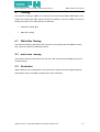
6.1
Future Developments:
The possible future
ture developments for this project can as following:
•
Presence detection of members, using Bluetooth enabled device such as mobile
phones, within the premises of the house.
•
Integration of home entertainment solutions such as media players, televisions and
such other devices.
•
Alert notification by means of email, text message and automated calls to users.
•
Use of multiple cameras installed within the house for surveillance and motion
detection.
•
User profile management to enable automatic event occurrences in presence of
different members.
SAMARTH GUPTA / UNIVERSAL HOME AUTOMATION CONTROLLER
32
School of Electronic, Communication and Electrical Engineering
BSc Final Year Project Report
REFERENCES
[1] Home Automation: Research Issues
http://www.mot.chalmers.se/dept/tso/haddon/EMTELHA.pdf
[2] Perceptive Automation
http://www.perceptiveautomation.com/phpBB2/viewtopic.php?t=1477
http://goprism.com:8000/controlpage?name=1st_floor
[3] A Timeline for Home Automation
http://www.eddriscoll.com/timeline.html
[4] Easy X10 Projects for Creating a Smart Home
http://books.google.co.uk/books?id=lwzUuahW4c0C&pg=PA19&lpg=PA19&dq=the+BSR+Sy
stem+X10+&source=web&ots=qIgsmBIAHs&sig=8dEWoH9BUr68cO1qf
stem+X10+&source=web&ots=qIgsmBIAHs&sig=8dEWoH9BUr68cO1qf9HDvjgGkc&hl=en#PPA20,M1
PPA20,M1
[5] The Complete Book of Electronic Security
http://books.google.co.uk/books?id=JTEuCu7YnKAC&pg=PA125&lpg=PA125&dq=Standards
+for+home+automation&source=web&ots=PHylYujR1s&sig=kQOzu1iLAr5Ru2
+for+home+automation&source=web&ots=PHylYujR1s&sig=kQOzu1iLAr5Ru2-Kw0NfcOYn9c&hl=en#PPA126,M1
[6] HiddenWires – home automation and control systems articles and whitepapers
http://hiddenwires.co.uk/resources/articlesautomation.html
[7] What is Home Automation?
http://home-automation.cuqr.com/
automation.cuqr.com/
[8] k8055 GM
http://www.boristheengineer.co.uk/gamemaker/gm_k8055.htm
[9] Velleman Inc
http://www.vellemanusa.com/us/enu/produc
http://www.vellemanusa.com/us/enu/product/view/?id=522053
[10] User Manual VM110 UK Rev2
http://www.vellemanusa.com/us/enu/product/view/?id=522053
SAMARTH GUPTA / UNIVERSAL HOME AUTOMATION CONTROLLER
33
School of Electronic, Communication and Electrical Engineering
BSc Final Year Project Report
BIBLIOGRAPHY
1. Paul Kimmel, “Advanced C# Programming”
2. Herbert Schildt, “The Complete Reference C# 2.0”
3. Ben Albahari, Peterr Drayton, Brad Merrill, “C# Essentials, 2
nd
Edition”
4. Anders Hejsberg and Scott Wiltamuth, C# Language Reference
5. Jeff Ferguson, Brian Patterson, Jason Beres,Pierre Boutquin, and Meeta Gupta,
Gupta “C#
Bible”
6. Microsoft C# Programming for the Absolute Beginner
7. John Paul Mueller, Visual C# .NET Developer’s Handbook
SAMARTH GUPTA / UNIVERSAL HOME AUTOMATION CONTROLLER
34
School of Electronic, Communication and Electrical Engineering
BSc Final Year Project Report
APPENDICES
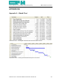
Appendix A - Ghantt Chart
Gantt chart Part I - showing the estimated start and finish dates of tasks
Gantt chart Part II - showing the estimated time-span for each task
SAMARTH GUPTA / UNIVERSAL HOME AUTOMATION CONTROLLER
35
School of Electronic, Communication and Electrical Engineering
BSc Final Year Project Report
Appendix B - Project Workflow Chart
SAMARTH GUPTA / UNIVERSAL HOME AUTOMATION CONTROLLER
36
School of Electronic, Communication and Electrical Engineering
BSc Final Year Project Report
Appendix D Login Page of the web (user) application
Main Menu (Homepage)
SAMARTH GUPTA / UNIVERSAL HOME AUTOMATION CONTROLLER
37
School of Electronic, Communication and Electrical Engineering
BSc Final Year Project Report
Controls for the eight Digital Outputs on the VM110 USB Interface Board
Controls for the two Analogue Outputs on the VM110 USB Interface Board
SAMARTH GUPTA / UNIVERSAL HOME AUTOMATION CONTROLLER
38
School of Electronic, Communication and Electrical Engineering
BSc Final Year Project Report
Security Controls (Motion Detection and Smoke Alarms, etc.)
Settings page to change personal details and preferences, add new members, etc.
SAMARTH GUPTA / UNIVERSAL HOME AUTOMATION CONTROLLER
39
School of Electronic, Communication and Electrical Engineering
BSc Final Year Project Report
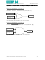
Appendix E - Logic Gates
Gate to change one digital output
put value
Digital Ouput Data to Switch a single output ON
New_Status = [BIN(Current_ Status) OR BIN(2 pow {outputNumber – 1}) ]
BIN(Current_ Status)
New_Status
BIN(2 pow
{outputNumber – 1})
Logic Gate to obtain digital output data to switch ON a single output
Digital Ouput Data to Switch a single output OFF
New Status = [BIN(CurrentStatus) AND BIN (255 – (2 pow {outputNumber – 1}))]
BIN(Current_ Status)
New_Status
BIN (255 – (2 pow
{outputNumber – 1}))
Logic Gate to obtain digital output data to switch OFF a single output
SAMARTH GUPTA / UNIVERSAL HOME AUTOMATION CONTROLLER
40