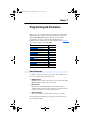
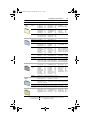
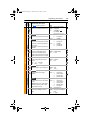
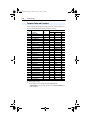
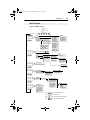
1
20B-UM001.book Page 1 Thursday, June 20, 2013 1:55 PM
User Manual
PowerFlex 700 AC Drives – Series A, Frames 0…6
Standard Control Firmware 3.001 and Below
Vector Control Firmware 3.002 and Below
20B-UM001.book Page 2 Thursday, June 20, 2013 1:55 PM
Important User Information
Read this document and the documents listed in the additional resources section about installation,
configuration, and operation of this equipment before you install, configure, operate, or maintain
this product. Users are required to familiarize themselves with installation and wiring instructions
in addition to requirements of all applicable codes, laws, and standards.
Activities including installation, adjustments, putting into service, use, assembly, disassembly, and
maintenance are required to be carried out by suitably trained personnel in accordance with
applicable code of practice.
If this equipment is used in a manner not specified by the manufacturer, the protection provided by
the equipment may be impaired.
In no event will Rockwell Automation, Inc. be responsible or liable for indirect or consequential
damages resulting from the use or application of this equipment.
The examples and diagrams in this manual are included solely for illustrative purposes. Because of
the many variables and requirements associated with any particular installation, Rockwell
Automation, Inc. cannot assume responsibility or liability for actual use based on the examples and
diagrams.
No patent liability is assumed by Rockwell Automation, Inc. with respect to use of information,
circuits, equipment, or software described in this manual.
Reproduction of the contents of this manual, in whole or in part, without written permission of
Rockwell Automation, Inc., is prohibited.
Throughout this manual, when necessary, we use notes to make you aware of safety considerations.
WARNING: Identifies information about practices or circumstances that can cause an
explosion in a hazardous environment, which may lead to personal injury or death,
property damage, or economic loss.
ATTENTION: Identifies information about practices or circumstances that can lead to
personal injury or death, property damage, or economic loss. Attentions help you
identify a hazard, avoid a hazard, and recognize the consequence.
IMPORTANT
Identifies information that is critical for successful application and understanding of the
product.
Labels may also be on or inside the equipment to provide specific precautions.
SHOCK HAZARD: Labels may be on or inside the equipment, for example, a drive or
motor, to alert people that dangerous voltage may be present.
BURN HAZARD: Labels may be on or inside the equipment, for example, a drive or
motor, to alert people that surfaces may reach dangerous temperatures.
ARC FLASH HAZARD: Labels may be on or inside the equipment, for example, a motor
control center, to alert people to potential Arc Flash. Arc Flash will cause severe injury or
death. Wear proper Personal Protective Equipment (PPE). Follow ALL Regulatory
requirements for safe work practices and for Personal Protective Equipment (PPE).
PowerFlex, DriveExplorer, DriveExecutive, PLC, Force Technology, DPI, and SCANport are either trademarks or registered
trademarks of Rockwell Automation, Inc.
ControlNet is a trademark of ControlNet International, Ltd.
DeviceNet is a trademark of the Open DeviceNet Vendor Association.
20B-UM001.book Page i Thursday, June 20, 2013 1:55 PM
Summary of Changes
The information below summarizes the changes to the PowerFlex 700
User Manual, publication 20B-UM001 since the last release.
Manual Updates
Description of New or Updated Information
Page
Removed the Installation/Wiring information (Chapter 1), Start Up information
(Chapter 2), dimension, specification and fuse/breaker information (Appendix
A). This information can now be found in the Installation Instructions:
PowerFlex 700 Adjustable Frequency AC Drive – Frames 0…6,
publication 20B-IN0019
–
20B-UM001.book Page ii Thursday, June 20, 2013 1:55 PM
soc-ii
Notes:
Summary of Changes
20B-UM001.book Page i Thursday, June 20, 2013 1:55 PM
Table of Contents
Important User Information . . . . . . . . . . . 1-2
Preface
Overview
Who Should Use this Manual? . . . . . . . . .
What Is Not in this Manual . . . . . . . . . . . .
Additional Resources . . . . . . . . . . . . . . . .
Manual Conventions . . . . . . . . . . . . . . . . .
General Precautions . . . . . . . . . . . . . . . . .
Catalog Number Explanation . . . . . . . . . .
Chapter 1
Programming
and Parameters
About Parameters . . . . . . . . . . . . . . . . . . . 1-1
How Parameters are Organized. . . . . . . . . 1-3
Monitor File . . . . . . . . . . . . . . . . . . . . . . 1-12
Motor Control File . . . . . . . . . . . . . . . . . 1-14
Speed Command File . . . . . . . . . . . . . . . 1-21
Dynamic Control File . . . . . . . . . . . . . . . 1-31
Utility File . . . . . . . . . . . . . . . . . . . . . . . . 1-38
Communication File . . . . . . . . . . . . . . . . 1-50
Inputs & Outputs File . . . . . . . . . . . . . . . 1-54
Applications File . . . . . . . . . . . . . . . . . . . 1-60
Parameter Cross Reference – by Name. . 1-61
Parameter Cross Reference – by Number 1-64
Chapter 2
Troubleshooting
Faults and Alarms . . . . . . . . . . . . . . . . . . . 2-1
Drive Status . . . . . . . . . . . . . . . . . . . . . . . . 2-2
Manually Clearing Faults . . . . . . . . . . . . . 2-3
Fault Descriptions . . . . . . . . . . . . . . . . . . . 2-4
Clearing Alarms . . . . . . . . . . . . . . . . . . . . 2-9
Alarm Descriptions . . . . . . . . . . . . . . . . . 2-10
Common Symptoms/Corrective Actions 2-13
Testpoint Codes and Functions . . . . . . . . 2-16
Appendix A
Supplemental
Drive Information
Drive Frame Sizes . . . . . . . . . . . . . . . . . . . A-1
Communication Configurations . . . . . . . . A-1
Appendix B
HIM Overview
External and Internal Connections . . . . . .
LCD Display Elements . . . . . . . . . . . . . . .
ALT Functions. . . . . . . . . . . . . . . . . . . . . .
Menu Structure . . . . . . . . . . . . . . . . . . . . .
Viewing and Editing Parameters . . . . . . . .
Linking Parameters (Vector Control Only)
Removing/Installing the HIM . . . . . . . . . .
P-1
P-1
P-2
P-2
P-3
P-5
B-1
B-2
B-2
B-3
B-5
B-6
B-8
20B-UM001.book Page ii Thursday, June 20, 2013 1:55 PM
ii
Table of Contents
Appendix C
Index
Application Notes
External Brake Resistor . . . . . . . . . . . . . . . C-1
Lifting/Torque Proving . . . . . . . . . . . . . . . C-2
Minimum Speed . . . . . . . . . . . . . . . . . . . . C-7
Motor Control Technology . . . . . . . . . . . . C-8
Motor Overload . . . . . . . . . . . . . . . . . . . . C-10
Overspeed . . . . . . . . . . . . . . . . . . . . . . . . C-11
Power Loss Ride Through . . . . . . . . . . . . C-12
Process PI for Standard Control . . . . . . . C-13
Reverse Speed Limit . . . . . . . . . . . . . . . . C-16
Skip Frequency . . . . . . . . . . . . . . . . . . . . C-17
Sleep Wake Mode . . . . . . . . . . . . . . . . . . C-19
Start At PowerUp. . . . . . . . . . . . . . . . . . . C-21
Stop Mode . . . . . . . . . . . . . . . . . . . . . . . . C-22
Voltage Tolerance . . . . . . . . . . . . . . . . . . C-24
20B-UM001.book Page 1 Thursday, June 20, 2013 1:55 PM
Preface
Overview
The purpose of this manual is to provide you with the basic information
needed to install, start-up and troubleshoot the PowerFlex 700
Adjustable Frequency AC Drive.
For information on . . .
Who Should Use this Manual?
What Is Not in this Manual
Additional Resources
Manual Conventions
General Precautions
Catalog Number Explanation
See page . . .
P-1
P-1
P-2
P-2
P-3
P-5
Who Should Use this Manual?
This manual is intended for qualified personnel. You must be able to
program and operate Adjustable Frequency AC Drive devices. In
addition, you must have an understanding of the parameter settings and
functions.
What Is Not in this Manual
The PowerFlex 700 Series A User Manual provides programming and
troubleshooting information for Standard Control and Vector Control
drives, Frames 0…6.
Drive installation and wiring information is not in this manual, but can
be found in the Installation Instructions for your drive:
Frames 0…6 – publication 20B-IN019
Literature is available online at http://www.rockwellautomation.com/
literature.
20B-UM001.book Page 2 Thursday, June 20, 2013 1:55 PM
P-2
Overview
Additional Resources
These documents contain additional information concerning related
products from Rockwell Automation.
Resource
Description
PowerFlex 700 AC Drive Technical Data,
publication 20B-TD001
This publication provides detailed drive
specifications, option specifications and input
protection device ratings.
PowerFlex Comm Adapter Manuals, publication
20COMM-UM…
These publications provide information on
configuring, using, and troubleshooting
PowerFlex communication adapters.
PowerFlex 70 and PowerFlex 700 Reference
Manual, publication PFLEX-RM001
These publications provide detailed application
specific information for programming and
configuring the PowerFlex 700 drive.
PowerFlex 70 Enhanced Control and PowerFlex
700 Vector Control Reference Manual,
publication PFLEX-RM004
Wiring and Grounding Guidelines for Pulse
Width Modulated (PWM) AC Drives, publication
DRIVES-IN001
Provides basic information needed to properly
wire and ground PWM AC drives.
Safety Guidelines for the Application, Installation
and Maintenance of Solid State Control,
publication SGI-1.1
Provides general guidelines for the application,
installation, and maintenance of solid-state
control.
Guarding Against Electrostatic Damage,
publication 8000-4.5.2
Provides practices for guarding against
Electrostatic damage (ESD)
Product Certifications website, http://ab.com
Provides declarations of conformity, certificates,
and other certification details.
You can view or download publications at
http:/www.rockwellautomation.com/literature/. To order paper copies of
technical documentation, contact your local Allen-Bradley distributor or
Rockwell Automation sales representative.
Manual Conventions
•
In this manual we refer to the PowerFlex 700 Adjustable Frequency
AC Drive as; drive, PowerFlex 700 or PowerFlex 700 Drive.
•
To help differentiate parameter names and LCD display text from
other text, the following conventions will be used:
–
Parameter Names will appear in [brackets].
For example: [DC Bus Voltage].
–
Display Text will appear in “quotes.” For example: “Enabled.”
20B-UM001.book Page 3 Thursday, June 20, 2013 1:55 PM
Overview
•
P-3
The following words are used throughout the manual to describe an
action:
Word
Can
Cannot
May
Must
Shall
Should
Should Not
Meaning
Possible, able to do something
Not possible, not able to do something
Permitted, allowed
Unavoidable, you must do this
Required and necessary
Recommended
Not recommended
General Precautions
!
!
!
!
!
ATTENTION: This drive contains ESD (Electrostatic Discharge)
sensitive parts and assemblies. Static control precautions are required
when installing, testing, servicing or repairing this assembly.
Component damage may result if ESD control procedures are not
followed. If you are not familiar with static control procedures,
reference A-B publication 8000-4.5.2, “Guarding Against Electrostatic
Damage” or any other applicable ESD protection handbook.
ATTENTION: An incorrectly applied or installed drive can result in
component damage or a reduction in product life. Wiring or application
errors, such as, undersizing the motor, incorrect or inadequate AC
supply, or excessive ambient temperatures may result in malfunction of
the system.
ATTENTION: Only qualified personnel familiar with adjustable
frequency AC drives and associated machinery should plan or
implement the installation, start-up and subsequent maintenance of the
system. Failure to comply may result in personal injury and/or
equipment damage.
ATTENTION: To avoid an electric shock hazard, verify that the
voltage on the bus capacitors has discharged before performing any
work on the drive. Measure the DC bus voltage at the +DC & –DC
terminals of the Power Terminal Block (refer to Installation Instructions
for location). The voltage must be zero.
ATTENTION: Risk of injury or equipment damage exists. DPI or
SCANport host products must not be directly connected together via
1202 cables. Unpredictable behavior can result if two or more devices
are connected in this manner.
20B-UM001.book Page 4 Thursday, June 20, 2013 1:55 PM
P-4
Overview
!
!
!
ATTENTION: An incorrectly applied or installed bypass system can
result in component damage or reduction in product life. The most
common causes are:
• Wiring AC line to drive output or control terminals.
• Improper bypass or output circuits not approved by Allen-Bradley.
• Output circuits which do not connect directly to the motor.
Contact Allen-Bradley for assistance with application or wiring.
ATTENTION: The “adjust freq” portion of the bus regulator function
is extremely useful for preventing nuisance overvoltage faults resulting
from aggressive decelerations, overhauling loads, and eccentric loads. It
forces the output frequency to be greater than commanded frequency
while the drive's bus voltage is increasing towards levels that would
otherwise cause a fault. However, it can also cause either of the
following two conditions to occur.
1. Fast positive changes in input voltage (more than a 10% increase
within 6 minutes) can cause uncommanded positive speed changes.
However an “OverSpeed Limit” fault will occur if the speed reaches
[Max Speed] + [Overspeed Limit]. If this condition is unacceptable,
action should be taken to 1) limit supply voltages within the
specification of the drive and, 2) limit fast positive input voltage
changes to less than 10%. Without taking such actions, if this
operation is unacceptable, the “adjust freq” portion of the bus
regulator function must be disabled (see parameters 161 and 162).
2. Actual deceleration times can be longer than commanded
deceleration times. However, a “Decel Inhibit” fault is generated if
the drive stops decelerating altogether. If this condition is
unacceptable, the “adjust freq” portion of the bus regulator must be
disabled (see parameters 161 and 162). In addition, installing a
properly sized dynamic brake resistor will provide equal or better
performance in most cases.
Important: These faults are not instantaneous. Test results have
shown that they can take between 2-12 seconds to
occur.
ATTENTION: Loss of control in suspended load applications can
cause personal injury and/or equipment damage. Loads must always be
controlled by the drive or a mechanical brake. Parameters 600-611 are
designed for lifting/torque proving applications. It is the responsibility
of the engineer and/or end user to configure drive parameters, test any
lifting functionality and meet safety requirements in accordance with all
applicable codes and standards.
20B-UM001.book Page 5 Thursday, June 20, 2013 1:55 PM
Overview
P-5
Catalog Number Explanation
20B
a
D
2P1
A
3
A
Y
N
A
E
C
0
NN
AD
b
c
d
e
f
g
h
i
j
k
l
m
n
a
e
Drive
j
HIM
Code
Type
Code
20B
PowerFlex 700
b
Voltage Rating
Code
Voltage
Ph.
Prechg.
Frames
B
240V AC
3
-
0…6
C
400V AC
3
-
0…6
D
480V AC
3
-
0…6
E
600V AC
3
-
0…6
F
690V AC
3
-
5…6
H
540V DC
Comm Slot
Operator Interface
Code
Network Type
0
Blank Cover
C
ControlNet (Coax)
3
LCD Display, Full Numeric Keypad
D
DeviceNet
J♦
Remote (Panel Mount), IP66, NEMA/UL
Type 12 Full Numeric LCD HIM
E
EtherNet/IP
N
None
K♦
Remote (Panel Mount), IP66, NEMA/UL
Type 12 Prog. Only LCD HIM
♦ Available with Frames 5…6 Stand-Alone IP54
drives (Enclosure Code "G").
k
Control & I/O
Code
f
Documentation
-
N
J
650V DC
-
N
5…6
Code
Type
N
325V DC
-
Y
5…6
5…6
A
Manual
Control
I/O Volts
A
Standard
24V DC/AC
B
Standard
115V AC
Vector Δ
24V DC
D
Vector Δ
115V AC
N
Standard
None
C
P
540V DC
-
Y
5…6
N
No Manual
R
650V DC
-
Y
5…6
Q
T
810V DC
-
Y
5…6
No Shipping Package
(Internal Use Only)
W
932V DC
-
Y
5…6
Δ Vector Control Option utilizes DPI Only.
l
g
c
Feedback
Code
Brake
Type
ND Output Rating
Code
w/Brake IGBT ‡
0
None
Example
Y
Yes
1
Encoder, 12V/5V
N
No
Code
Amps
kW (Hp)
2P2
2.2
0.37 (0.5)
022
22
5.5 (7.5)
‡ Brake IGBT is standard on Frames 0-3,
optional on Frames 4-6.
m
Future Use
d
h
Enclosure
n
Internal Braking Resistor
Code
Enclosure
Code
A
IP20, NEMA/UL Type 1
Y
F♠
Open/Flange Mount
Front: IP00, NEMA/UL Type Open
Back/Heatsink: IP54, NEMA Type 12
N
G♠
Stand-Alone/Wall Mount
IP54, NEMA/UL Type 12
w/Resistor
Yes
No
Not available for Frame 3 drives or larger.
♠ Only available for Frame 5 & Frame 6 drives,
400…690V.
Special Firmware (Frames 0…6 Only)
Code
Type
AD ♦
60 Hz Maximum
AE ♦
Cascading Fan/Pump Control
AX ♦
82 Hz Maximum
BA ♦
Pump Off (for pump jack)
♦ Must be used with Vector Control option C or
D (Position k). Positions m-n are only required
when custom firmware is supplied.
i
Emission
Code
CE Filter §
CM Choke
Yes
A
Yes
B#
Yes
No
N
No
No
§ Note: 600V class drives below 77 Amps
(Frames 0-4) are declared to meet the Low
Voltage Directive. It is the responsibility of the
user to determine compliance to the EMC
directive.
# Only available for 208…240V Frame 0-3 drives.
20B-UM001.book Page 6 Thursday, June 20, 2013 1:55 PM
P-6
Notes:
Overview
20B-UM001.book Page 1 Thursday, June 20, 2013 1:55 PM
Chapter 1
Programming and Parameters
Chapter 3 provides a complete listing and description of the PowerFlex
700 parameters. The parameters can be programmed (viewed/edited)
using an LCD HIM (Human Interface Module). As an alternative,
programming can also be performed using DriveExplorer™ or
DriveExecutive™ software and a personal computer. Refer to Appendix
B for a brief description of the LCD HIM.
For information on . . .
About Parameters
How Parameters are Organized
Monitor File
Motor Control File
Speed Command File
Dynamic Control File
Utility File
Communication File
Inputs & Outputs File
Applications File
Parameter Cross Reference – by Name
Parameter Cross Reference – by Number
See page . . .
1-1
1-3
1-12
1-14
1-21
1-31
1-38
1-50
1-54
1-60
1-62
1-65
About Parameters
To configure a drive to operate in a specific way, drive parameters may
have to be set. Three types of parameters exist:
•
ENUM Parameters
ENUM parameters allow a selection from 2 or more items. The LCD
HIM will display a text message for each item.
•
Bit Parameters
Bit parameters have individual bits associated with features or
conditions. If the bit is 0, the feature is off or the condition is false. If
the bit is 1, the feature is on or the condition is true.
•
Numeric Parameters
These parameters have a single numerical value (i.e. 0.1 Volts).
The example on the following page shows how each parameter type is
presented in this manual.
20B-UM001.book Page 2 Thursday, June 20, 2013 1:55 PM
Programming and Parameters
No.
Group
File
➊➋➌➍
➎
Parameter Name & Description
Loads a previously saved set of
parameter values from a selected user
set location in drive nonvolatile memory
to active drive memory.
Values
Default:
Options:
0
“Ready”
0
1
2
3
“Ready”
“User Set 1”
“User Set 2”
“User Set 3”
199
216 [Dig In Status]
Diagnostics
Status of the digital
inputs.
Dig
i
Dig tal In
6
i
Dig tal In
5
i
Dig tal In
it 4
Dig al In
3
i
Dig tal In
ita 2
l In
1
UTILITY
Drive . . .
198 [Load Frm Usr Set]
➏
Related
1-2
x x x x x x x x x x 0 0 0 0 0 0
15 14 13 12 11 10 9 8 7 6 5 4 3 2 1 0
1 =Input Present
0 =Input Not Present
x =Reserved
No.
➊
➋
➌
Torq . . .
MOTOR . . .
Bit #
434
Vector
[Torque Ref B Mult]
➎
➏
1.0
Description
File – Lists the major parameter file category.
Group – Lists the parameter group within a file.
No. – Parameter number.
32
➍
Default:
FV Defines the value of the multiplier for the Min/Max: –/+32767.0
[Torque Ref B Sel] selection.
Units:
0.1
= Parameter value can not be changed until drive is stopped.
= 32 bit parameter in the Standard Control option. All
parameters in the Vector Control option are 32 bit.
FV = Parameter only displayed when [Motor Cntl Sel] is set to “4.”
Parameter Name & Description – Parameter name as it appears on an LCD HIM, with a brief
description of the parameters function.
Standard = This parameter is specific to the Standard Control Option.
= This parameter will only be available with the Vector Control option.
Vector
Vector v3 = Only available with Vector Control option firmware version 3.xxx & later.
Values – Defines the various operating characteristics of the parameter. Three types exist.
ENUM Default:
Lists the value assigned at the factory. “Read Only” = no default.
Options:
Displays the programming selections available.
Bit
Bit:
Lists the bit place holder and definition for each bit.
Numeric Default:
Lists the value assigned at the factory. “Read Only” = no default.
Min/Max:
The range (lowest and highest setting) possible for the parameter.
Units:
Unit of measure and resolution as shown on the LCD HIM.
Important: Some parameters will have two unit values:
• Analog inputs can be set for current or voltage with [Anlg In Config], param. 320.
• Setting [Speed Units], parameter 79 on Vector Control drives selects Hz or RPM.
• Values that pertain to Vector Control drives only will be indicated by “ Vector ” or
“ v3 ” for Vector firmware 3.xxx and later.
Important: When sending values through DPI ports, simply remove the decimal
point to arrive at the correct value (i.e. to send “5.00 Hz,” use “500”).
Related – Lists parameters (if any) that interact with the selected parameter. The symbol “ ”
indicates that additional parameter information is available in Appendix C.
20B-UM001.book Page 3 Thursday, June 20, 2013 1:55 PM
Programming and Parameters
1-3
How Parameters are Organized
The LCD HIM displays parameters in a File-Group-Parameter or
Numbered List view order. To switch display mode, access the Main
Menu, press ALT, then Sel while cursor is on the parameter selection. In
addition, using [Param Access Lvl], the user has the option to display all
parameters, commonly used parameters or diagnostic parameters.
Control Options
Two different control options are
available for the PowerFlex 700;
Standard and Vector. The Standard
Control option provides typical Volts
per Hertz and Sensorless Vector
operation. The Vector Control option
provides the added capability of FVC
Vector control. The cassette
determines the type of control you
have available (see diagram).
Standard Control
Option
Vector Control
Option
To simplify programming with the
Vector Control option, the displayed
parameters will change according to
the selection made with [Motor Cntl
Sel]. For example, if “FVC Vector” is
selected, the parameters associated solely with other operations such as
Volts per Hertz or Sensorless Vector will be hidden. Refer to pages 1-4
through 1-8.
File-Group-Parameter Order
This simplifies programming by grouping parameters that are used for
similar functions. The parameters are organized into files. Each file is
divided into groups, and each parameter is an element in a group. By
default, the LCD HIM displays parameters by File-Group-Parameter
view.
Numbered List View
All parameters are in numerical order.
20B-UM001.book Page 4 Thursday, June 20, 2013 1:55 PM
1-4
Programming and Parameters
Basic Parameter View – Standard Control Option
Parameter 196 [Param Access Lvl] set to option 0 “Basic.”
File
Group
Parameters
Monitor
Metering
Output Freq
Commanded Freq
Output Current
DC Bus Voltage
001
002
003
012
Motor Data
Motor NP Volts
Motor NP FLA
Motor NP Hertz
041
042
043
Torq Attributes
Torque Perf Mode 053
Maximum Voltage 054
Spd Mode &
Limits
Minimum Speed 081
Maximum Speed 082
Speed
References
Speed Ref A Sel 090
Speed Ref B Sel 093
Speed Ref A Hi 091
Discrete
Speeds
Jog Speed
100
Preset Speed 1-7 101-107
Ramp Rates
Accel Time 1
Accel Time 2
140
141
Load Limits
Current Lmt Sel
Current Lmt Val
147
148
Stop/Brake
Modes
Stop Mode A
Stop Mode B
Monit
or
Motor Control
Motor
Contr
ol
Speed
Command
Speed
Comm
and
Dynamic
Control
Dynami
c Contr
Utility
Inputs &
Outputs
Inputs
&
Outpu
ts
Motor OL Hertz
047
Maximum Freq
Autotune
055
061
Speed Ref B Hi
Speed Ref A Lo
Speed Ref B Lo
094
092
095
TB Man Ref Sel
TB Man Ref Hi
TB Man Ref Lo
096
097
098
Decel Time 1
Decel Time 2
142
143
S-Curve %
146
155
156
DC Brk Lvl Sel
DC Brake Level
DC Brake Time
157
158
159
Bus Reg Mode A 161
Bus Reg Mode B 162
DB Resistor Type 163
Restart Modes
Start At PowerUp 168
Auto Rstrt Tries
174
Auto Rstrt Delay
Power Loss
Power Loss Mode 184
Power Loss Time 185
ol
Utility
Motor NP RPM
044
Motor NP Power 045
Mtr NP Pwr Units 046
Direction Config Direction Mode
190
Drive Memory
Param Access Lvl 196
Reset To Defalts 197
Load Frm Usr Set 198
Faults
Fault Config 1
238
Analog Inputs
Anlg In Config
Analog In1 Hi
Analog In2 Hi
320
322
325
Analog Outputs Analog Out1 Sel
Analog Out1 Hi
Analog Out1 Lo
Save To User Set 199
Language
201
Analog In1 Lo
Analog In2 Lo
323
326
Dig Out1 Level
Dig Out2 Level
381
385
342
343
344
Digital Inputs
Digital In1-6 Sel
361-366
Digital Outputs
Digital Out1 Sel
Digital Out2 Sel
380
384
175
20B-UM001.book Page 5 Thursday, June 20, 2013 1:55 PM
Programming and Parameters
1-5
Basic Parameter View – Vector Control Option
Parameter 196 [Param Access Lvl] set to option 0 “Basic.”
File
Group
Parameters
Monitor
Metering
Output Freq
001
Commanded Speed002
Commanded Torque**024
Output Current
003
Torque Current
004
DC Bus Voltage 012
Motor Data
Motor NP Volts
Motor NP FLA
Motor NP Hertz
041
042
043
Motor NP RPM
044
Motor NP Power 045
Mtr NP Pwr Units 046
Motor OL Hertz
Motor Poles
Torq Attributes
Motor Cntl Sel
Maximum Voltage
Maximum Freq
Autotune
053
054
055
061
Autotune Torque** 066
Inertia Autotune** 067
Torque Ref A Sel** 427
Torque Ref A Hi** 428
Torque Ref A Lo** 429
Pos Torque Limit** 436
Neg Torque Limit** 437
Speed
Feedback
Motor Fdbk Type 412
Encoder PPR
Spd Mode &
Limits
Speed Units
079
Feedback Select 080
Minimum Speed 081
Maximum Speed 082
Rev Speed Limit** 454
Speed
References
Speed Ref A Sel
Speed Ref A Hi
Speed Ref A Lo
Speed Ref B Sel
Speed Ref B Hi
Speed Ref B Lo
TB Man Ref Sel
TB Man Ref Hi
TB Man Ref Lo
Pulse Input Ref
098
099
Discrete
Speeds
Jog Speed 1
100
Jog Speed 2
Preset Speed 1-7 101-107
108
Ramp Rates
Accel Time 1
Accel Time 2
140
141
Decel Time 1
Decel Time 2
142
143
S-Curve %
146
Load Limits
Current Lmt Sel
147
Current Lmt Val
148
Stop/Brake
Modes
Stop/Brk Mode A 155
Stop/Brk Mode B 156
DC Brk Lvl Sel
DC Brake Level
DC Brake Time
157
158
159
Restart Modes
Start At PowerUp 168
Auto Rstrt Tries
174
Power Loss
Power Loss Mode 184
Power Loss Time 185
Power Loss Level 186
Monit
or
Motor Control
Motor
Contr
ol
Speed
Command
Speed
Comm
and
Dynamic
Control
Dynami
c Contr
413
094
095
096
097
ol
Utility
Utility
Inputs &
Outputs
Inputs
&
090
091
092
093
047
049
Outpu
ts
Direction Config Direction Mode
Bus Reg Mode A 161
Bus Reg Mode B 162
DB Resistor Type 163
Auto Rstrt Delay
175
190
Drive Memory
Param Access Lvl 196
Reset To Defalts 197
Load Frm Usr Set 198
Save To User Set 199
Language
201
Diagnostics
Start Inhibits
214
Dig In Status
216
Dig Out Status
217
Faults
Fault Config 1
238
Alarms
Alarm Config 1
259
Analog Inputs
Anlg In Config
Analog In1 Hi
Analog In1 Lo
320
322
323
Analog In2 Hi
Analog In2 Lo
325
326
Analog Outputs Analog Out1, 2 Sel 342
Analog Out1 Hi 343
Analog Out1, 2 Lo 344
Analog Out1, 2 Sel 345
Digital Inputs
Digital In1-6 Sel
Digital Outputs
Digital Out1-3 Sel 380-388 Dig Out1-3 Level 381-389
Analog Out2 Hi 346
Analog Out1, 2 Lo 347
361-366
** These parameters will only be displayed when parameter 053 [Motor Cntl Sel] is set to option “4.”
20B-UM001.book Page 6 Thursday, June 20, 2013 1:55 PM
1-6
Programming and Parameters
Advanced Parameter View – Standard Control Option
Parameter 196 [Param Access Lvl] set to option 1 “Advanced.”
File
Group
Parameters
Monitor
Metering
Output Freq
Commanded Freq
Output Current
Torque Current
Flux Current
001
002
003
004
005
Output Voltage
006
Output Power
007
Output Powr Fctr 008
Elapsed MWh
009
Elapsed Run Time 010
Drive Data
Rated kW
Rated Volts
026
027
Rated Amps
Control SW Ver
028
029
Motor Data
Motor Type
Motor NP Volts
Motor NP FLA
Motor NP Hertz
040
041
042
043
Motor NP RPM
Motor NP Power
Mtr NP Pwr Units
Motor OL Hertz
Torq Attributes
Torque Perf Mode
Maximum Voltage
Maximum Freq
Compensation
053
054
055
056
Flux Up Mode
Flux Up Time
SV Boost Filter
Autotune
Volts per Hertz
Start/Acc Boost
Run Boost
069
070
Break Voltage
071
Break Frequency 072
Spd Mode &
Limits
Speed Mode
080
Minimum Speed 081
Maximum Speed 082
Overspeed Limit 083
Skip Frequency 1 084
Skip Frequency 2 085
Skip Frequency 3 086
Skip Freq Band 087
Speed
References
Speed Ref A Sel 090
Speed Ref A Hi 091
Speed Ref A Lo 092
Speed Ref B Sel 093
Speed Ref B Hi 094
Speed Ref B Lo 095
TB Man Ref Sel
TB Man Ref Hi
TB Man Ref Lo
096
097
098
Discrete
Speeds
Jog Speed
100
Preset Speed 1-7 101-107
Speed Trim
Trim In Select
Trim Out Select
Slip Comp
Monit
or
Motor Control
Motor
Contr
ol
Speed
Command
Speed
MOP Frequency
DC Bus Voltage
DC Bus Memory
Analog In1 Value
Analog In2 Value
011
012
013
016
017
044
045
046
047
Motor OL Factor
048
057
058
059
061
IR Voltage Drop 062
Flux Current Ref 063
IXo Voltage Drop 064
Comm
and
Dynamic
Control
Dynami
c Contr
Trim Hi
Trim Lo
119
120
Slip RPM @ FLA 121
Slip Comp Gain 122
Slip RPM Meter
123
Process PI
PI Configuration
PI Control
PI Reference Sel
PI Setpoint
PI Feedback Sel
124
125
126
127
128
PI Integral Time
PI Prop Gain
PI Lower Limit
PI Upper Limit
PI Preload
129
130
131
132
133
PI Status
PI Ref Meter
PI Fdback Meter
PI Error Meter
PI Output Meter
134
135
136
137
138
Ramp Rates
Accel Time 1
Accel Time 2
140
141
Decel Time 1
Decel Time 2
142
143
S Curve %
146
Load Limits
Current Lmt Sel 147
Current Lmt Val 148
Current Lmt Gain 149
Drive OL Mode
150
PWM Frequency 151
Stop/Brake
Modes
Stop Mode A
Stop Mode B
DC Brake Lvl Sel
DC Brake Level
155
156
157
158
DC Brake Time
Bus Reg Ki
Bus Reg Mode A
Bus Reg Mode B
159
160
161
162
DB Resistor Type 163
Bus Reg Kp
164
Bus Reg Kd
165
Restart Modes
Start At PowerUp
Flying Start En
Flying StartGain
Auto Rstrt Tries
168
169
170
174
Auto Rstrt Delay
Sleep Wake-Mode
Sleep-Wake Ref
Wake Level
175
178
179
180
Wake Time
Sleep Level
Sleep Time
Power Loss
Power Loss Mode 184
Power Loss Time 185
Power Loss Level 186
ol
117
118
181
182
183
20B-UM001.book Page 7 Thursday, June 20, 2013 1:55 PM
Programming and Parameters
File
Group
Utility
Direction Config Direction Mode
Parameters
190
HIM Ref Config Save HIM Ref
192
Man Ref Preload 193
Utility
MOP Config
Save MOP Ref
MOP Rate
Drive Memory
Param Access Lvl 196
Reset To Defalts 197
Load Frm Usr Set 198
Save To User Set 199
Reset Meters
200
Language
201
Voltage Class
Drive Checksum
202
203
Diagnostics
Drive Status 1
Drive Status 2
Drive Alarm 1
Drive Alarm 2
Speed Ref Source
Start Inhibits
Last Stop Source
Dig In Status
209
210
211
212
213
214
215
216
Dig Out Status
Drive Temp
Drive OL Count
Motor OL Count
Fault Speed
Fault Amps
Fault Bus Volts
Status 1 @ Fault
Status 2 @ Fault
Alarm 1 @ Fault
Alarm 2 @ Fault
Testpoint 1 Sel
Testpoint 1 Data
Testpoint 2 Sel
Testpoint 2 Data
228
229
230
234
235
236
237
Faults
Fault Config 1
Fault Clear
238
240
Fault Clear Mode 241
Power Up Marker 242
Fault 1-8 Code
Fault 1-8 Time
243-257
244-258
Alarms
Alarm Config 1
Alarm Clear
259
261
Alarm1-8 Code
262-269
DPI Baud Rate
Drive Logic Rslt
270
271
Drive Ref Rslt
Drive Ramp Rslt
272
273
Masks &
Owners
Logic Mask
Start Mask
Jog Mask
Direction Mask
Reference Mask
Accel Mask
Decel Mask
276
277
278
279
280
281
282
Fault Clr Mask
MOP Mask
Local Mask
Stop Owner
Start Owner
Jog Owner
Direction Owner
283
284
285
288
289
290
291
Reference Owner
Accel Owner
Decel Owner
Fault Clr Owner
MOP Owner
Local Owner
292
293
294
295
296
297
Datalinks
Data In A1-D2
Data Out A1-D2
300-307
310-317
Analog Inputs
Anlg In Config
Anlg In Sqr Root
Analog In 1 Hi
320
321
322
Analog In 2 Hi
Analog In 1 Lo
Analog In 2 Lo
325
323
326
Anlg In 1 Loss
Anlg In 2 Loss
324
327
Analog Out1 Hi
Analog Out1 Lo
343
344
Communication Comm Control
Comm
unica
tion
Inputs &
Outputs
Inputs
&
1-7
Outpu
ts
194
195
Analog Outputs Anlg Out Config 340
Anlg Out Absolut 341
Analog Out1 Sel 342
Digital Inputs
Digital In1-6 Sel
361-366
Digital Outputs
Digital Out1 Sel
Digital Out2 Sel
Dig Out1 Level
380
384
381
217
218
219
220
224
225
226
227
Dig Out2 Level
385
Dig Out1 OnTime 382
Dig Out2 OnTime 386
Dig Out1 OffTime 383
Dig Out2 OffTime 387
20B-UM001.book Page 8 Thursday, June 20, 2013 1:55 PM
1-8
Programming and Parameters
Advanced Parameter View – Vector Control Option
Parameter 196 [Param Access Lvl] set to option 1 “Advanced.”
File
Group
Parameters
Monitor
Metering
Output Freq
001
Commanded Speed 002
Ramped Speed 022
Speed Reference 023
Commanded Torque**024
Speed Feedback 025
Output Current
003
Torque Current
004
Flux Current
005
Output Voltage
006
Output Power
007
Output Powr Fctr 008
Elapsed MWh
009
Elapsed Run Time 010
Drive Data
Rated kW
Rated Volts
026
027
Rated Amps
Control SW Ver
028
029
Motor Data
Motor Type
Motor NP Volts
Motor NP FLA
Motor NP Hertz
040
041
042
043
Motor NP RPM
Motor NP Power
Mtr NP Pwr Units
Motor OL Hertz
044
045
046
047
Torq Attributes
Motor Cntl Sel
Maximum Voltage
Maximum Freq
Compensation
Flux Up Mode
Flux Up Time
SV Boost Filter
Autotune
IR Voltage Drop
053
054
055
056
057
058
059
061
062
Flux Current Ref 063
IXo Voltage Drop 064
Autotune Torque** 066
Inertia Autotune** 067
Torque Ref A Sel** 427
Torque Ref A Hi** 428
Torque Ref A Lo** 429
Torq Ref A Div** 430
Torque Ref B**
431
Volts per Hertz
Start/Acc Boost
Run Boost*
069
070
Break Voltage*
071
Break Frequency* 072
Speed
Feedback
Motor Fdbk Type
Encoder PPR
Enc Position Fdbk
Encoder Speed
412
413
414
415
Fdbk Filter Sel
416
Notch Filter Freq** 419
Notch Filter K** 420
Marker Pulse
Pulse In Scale
Encoder Z Chan
Spd Mode &
Limits
Speed Units
Feedback Select
Minimum Speed
Maximum Speed
079
080
081
082
Overspeed Limit 083
Skip Frequency 1* 084
Skip Frequency 2* 085
Skip Frequency 3* 086
Skip Freq Band* 087
Speed/Torque Mod**088
Rev Speed Limit** 454
Speed
References
Speed Ref A Sel
Speed Ref A Hi
Speed Ref A Lo
Speed Ref B Sel
090
091
092
093
Speed Ref B Hi
Speed Ref B Lo
TB Man Ref Sel
TB Man Ref Hi
TB Man Ref Lo
Pulse Input Ref
Discrete
Speeds
Jog Speed 1
100
Preset Speed 1-7 101-107 Jog Speed 2
108
Speed Trim
Trim In Select
Trim Out Select
117
118
Trim Hi
Trim Lo
116 3.x
Monit
or
Motor Control
Motor
Contr
ol
Speed
Command
Speed
Comm
and
Dynamic
Control
Dynami
c Contr
ol
094
095
096
MOP Reference
DC Bus Voltage
DC Bus Memory
Analog In1 Value
Analog In2 Value
Elapsed kWh
011
012
013
016
017
014 3.x
Motor OL Factor
Motor Poles
048
049
Torque Ref B Hi** 432
Torque Ref B Lo** 433
Torq Ref B Mult** 434
Torque Setpoint** 435
Torque Setpoint 2**438 3.x
Pos Torque Limit** 436
Neg Torque Limit** 437
Control Status** 440
Mtr Tor Cur Ref** 441
119
120
Trim % Setpoint
421
422
423
097
098
099
Slip Comp
Slip RPM @ FLA 121
Slip Comp Gain* 122
Slip RPM Meter
123
Process PI
PI Configuration
PI Control
PI Reference Sel
PI Setpoint
PI Feedback Sel
PI Integral Time
PI Prop Gain
PI Lower Limit
PI Upper Limit
PI Preload
PI Status
PI Ref Meter
PI Fdback Meter
PI Error Meter
PI Output Meter
PI Reference Hi
PI Reference Lo
PI Feedback Hi
PI Feedback Lo
PI BW Filter
PI Deriv Time
138
460
461
462
463
139 2.x
459 3.x
Speed
Regulator
Ki Speed Loop** 445
Kp Speed Loop** 446
Ramp Rates
Accel Time 1, 2
Load Limits
Current Lmt Sel 147
Current Lmt Val 148
Current Lmt Gain 149
124
125
126
127
128
129
130
131
132
133
134
135
136
137
Kf Speed Loop**
447
Speed Desired BW** 449
140,141 Decel Time 1, 2
Total Inertia**
450
Speed Loop Meter** 451 3.x
142,143 S Curve %
Drive OL Mode
150
PWM Frequency 151
Droop RPM @ FLA152
146
Regen Power Limit**153
Current Rate Limit **154
20B-UM001.book Page 9 Thursday, June 20, 2013 1:55 PM
Programming and Parameters
1-9
File
Group
Parameters
Dynamic
Control
continued
Stop/Brake
Modes
Stop/Brk Mode
DC Brk Lvl Sel
DC Brake Level
DC Brake Time
155,156
157
158
159
Bus Reg Ki*
Bus Reg Mode
DB Resistor Type
Bus Reg Kp*
Bus Reg Kd*
165
160
166
161,162 Flux Braking
163
DB While Stopped 145 3.x
164
Restart Modes
Start At PowerUp
Flying Start En
Flying StartGain
Auto Rstrt Tries
168
169
170
174
Auto Rstrt Delay
Sleep-Wake Mode
Sleep-Wake Ref
Wake Level
175
178
179
180
Wake Time
Sleep Level
Sleep Time
Powerup Delay
181
182
183
167
Power Loss
Power Loss Mode 184
Power Loss Time 185
Power Loss Level 186
Load Loss Level
Load Loss Time
Shear Pin Time
187 3.x
188 3.x
189 3.x
Gnd Warn Level
177 3.x
202
203
Dynami
c Contr
ol
Utility
Direction Config Direction Mode
190
HIM Ref Config Save HIM Ref
192
MOP Config
Save MOP Ref
194
Drive Memory
Param Access Lvl 196
Reset To Defalts 197
Load Frm Usr Set 198
Save To User Set 199
Reset Meters
200
Language
201
Voltage Class
Drive Checksum
Diagnostics
Drive Status 1, 2
Drive Alarm 1, 2
Speed Ref Source
Start Inhibits
Last Stop Source
Dig In Status
209,210
211,212
213
214
215
216
Dig Out Status
Drive Temp
Drive OL Count
Motor OL Count
Fault Speed
Fault Amps
Fault Bus Volts
226
Status 1,2 @ Fault 227,228
Alarm 1,2 @ Fault 229,230
Testpoint 1,2 Sel 234,236
Testpoint 1,2 Data 235,237
Faults
Fault Config 1
Fault Clear
238
240
Fault Clear Mode 241
Power Up Marker 242
Fault 1-8 Code
Fault 1-8 Time
243-257
244-258
Alarms
Alarm Config 1
259
Alarm Clear
Alarm1-8 Code
262-269
Scaled Blocks
Scale1, 2 In Val
Scale3, 4 In Val
Scale1, 2 In Hi
Scale3, 4 In Hi
Communication Comm Control
DPI Baud Rate
Drive Logic Rslt
Masks &
Owners
Logic Mask
Start Mask
Jog Mask
Direction Mask
Reference Mask
Accel Mask
Decel Mask
Fault Clr Mask
Datalinks
Data In A1-D2
300-307 Data Out A1-D2
310-317
Analog Inputs
Anlg In Config
Anlg In Sqr Root
320
321
322,325 Analog In1, 2 Loss 324,327
323,326
Utility
Comm
unica
tion
Inputs &
Outputs
Inputs
&
MOP Rate
195
217
218
219
220
224
225
261
Scale1, 2 In Lo 478,484
Scale3, 4 In Lo 490,496 3.x
Scale1, 2 Out Hi 479,485
Scale3, 4 Out Hi 491,497 3.x
Scale1,2 Out Lo 480,486
Scale3,4 Out Lo 492,488 3.x
Scale1,2 Out Val 481,487
Scale3,4 Out Val 493,499 3.x
270
271
Drive Ref Rslt
Drive Ramp Rslt
272
273
DPI Port Sel
DPI Port Value
274
275
276
277
278
279
280
281
282
283
MOP Mask
Local Mask
Stop Owner
Start Owner
Jog Owner
Direction Owner
Reference Owner
Accel Owner
284
285
288
289
290
291
292
293
Decel Owner
Fault Clr Owner
MOP Owner
Local Owner
DPI Ref Select
DPI Fdbk Select
294
295
296
297
298 3.x
299 3.x
Analog In1, 2 Hi
Analog In1, 2 Lo
Analog Outputs Anlg Out Config 340
Analog Out1, 2 Hi 343,346 Anlg Out1,2 Scal 354,355 3.x
Anlg Out Absolut 341
Analog Out1, 2 Lo 344,347 Anlg1 Out Setpt 377,378 3.x
Analog Out1, 2 Sel 342,345
Outpu
ts
Applications 3.x
Applica
tions
476,482
488,494 3.x
477,483
489,495 3.x
Man Ref Preload 193
Digital Inputs
Digital In1-6 Sel
Digital Outputs
Digital Out Sel 380,384,388 Dig Out OnTime 382,386,390 Dig Out Setpt
Dig Out Level 381,385,389 Dig Out OffTime 383,387,391
361-366
Torq Proving 3.x
TorqProve Cnfg
TorqProve Setup
Spd Dev Band
SpdBand Integrat
600 3.x
601 3.x
602 3.x
603 3.x
Brk Release Time 604 3.x
ZeroSpdFloatTime 605 3.x
Float Tolerance 606 3.x
Brk Set Time
607 3.x
TorqLim SlewRate
BrkSlip Count
Brk Alarm Travel
MicroPos Scale%
379 3.x
608 3.x
609 3.x
610 3.x
611 3.x
* These parameters will only be displayed when parameter 053 [Motor Cntl Sel] is set to option “2 or 3.”
** These parameters will only be displayed when parameter 053 [Motor Cntl Sel] is set to option “4.”
2.x Firmware 2.001 & later only.
3.x Firmware 3.001 & later only.
20B-UM001.book Page 10 Thursday, June 20, 2013 1:55 PM
1-10
Programming and Parameters
Basic Fan/Pump Parameter View (1) – Standard Control Option
Parameter 196 [Param Access Lvl] set to option 3 “Fan/Pump.”
File
Group
Parameters
Monitor
Metering
Output Freq
Commanded Freq
Output Current
Output Power
001
002
003
007
Elapsed MWh
009
Elapsed Run Time 010
DC Bus Voltage 012
Analog In1 Value 016
Motor Data
Motor NP Volts
Motor NP FLA
Motor NP Hertz
041
042
043
Motor NP RPM
044
Motor NP Power 045
Mtr NP Pwr Units 046
Torq Attributes
Maximum Voltage 054
Maximum Freq
055
Volts per Hertz
Start/Acc Boost
Run Boost
069
070
Break Voltage
071
Break Frequency 072
Spd Mode &
Limits
Speed Mode
080
Minimum Speed 081
Maximum Speed 082
Overspeed Limit 083
Skip Frequency 1 084
Skip Freq Band 087
Speed
References
Speed Ref A Sel 090
Speed Ref A Hi 091
Speed Ref A Lo 092
Discrete
Speeds
Preset Speed 2
102
Ramp Rates
Accel Time 1
Decel Time 1
140
142
Load Limits
Current Lmt Val
148
Stop/Brake
Modes
Stop Mode A
155
Restart Modes
Start At PowerUp 168
Auto Rstrt Tries 174
Auto Rstrt Delay 175
Drive Memory
Param Access Lvl 196
Reset To Defalts 197
Language
201
Diagnostics
Start Inhibits
Dig In Status
Dig Out Status
214
216
217
Analog Inputs
Anlg In Config
Anlg In Sqr Root
Analog In 1 Hi
320
321
322
Analog In 1 Lo
Anlg In 1 Loss
323
324
Analog Outputs Anlg Out Config
Analog Out1 Sel
340
342
Analog Out1 Hi
Analog Out1 Lo
343
344
Dig Out2 Level
385
Monit
or
Motor Control
Motor
Contr
ol
Speed
Command
Speed
Comm
and
Dynamic
Control
Dynami
c Contr
ol
Utility
Utility
Inputs &
Outputs
Inputs
&
Outpu
ts
Digital Inputs
Digital In1-6 Sel
361-366
Digital Outputs
Digital Out1 Sel
Digital Out2 Sel
Dig Out1 Level
380
384
381
(1) Only available on Standard Control drives with firmware version 3.001 or above.
20B-UM001.book Page 11 Thursday, June 20, 2013 1:55 PM
Programming and Parameters
1-11
Advanced Fan/Pump Parameter View (1) – Standard Control Option
Parameter 196 [Param Access Lvl] set to option 4 “Adv Fan/Pump.”
File
Group
Parameters
Monitor
Metering
Output Freq
Commanded Freq
Output Current
Output Power
Elapsed MWh
001
002
003
007
009
Elapsed Run Time 010
DC Bus Voltage 012
Analog In1 Value 016
Analog In2 Value 017
Motor Data
Motor NP Volts
Motor NP FLA
041
042
Motor NP Hertz
Motor NP RPM
043
044
Torq Attributes
Torque Perf Mode 053
Maximum Voltage 054
Maximum Freq
055
Volts per Hertz
Start/Acc Boost
Run Boost
069
070
Break Voltage
071
Break Frequency 072
Spd Mode &
Limits
Speed Mode
080
Minimum Speed 081
Maximum Speed 082
Overspeed Limit 083
Skip Frequency 1 084
Skip Frequency 2 085
Skip Frequency 3 086
Skip Freq Band 087
Speed
References
Speed Ref A Sel 090
Speed Ref A Hi 091
Speed Ref A Lo 092
Speed Ref B Sel 093
Speed Ref B Hi
Speed Ref B Lo
094
095
Discrete
Speeds
Preset Speed 2-4 102-104
Process PI
PI Configuration
PI Control
PI Reference Sel
PI Setpoint
PI Feedback Sel
124
125
126
127
128
PI Integral Time
PI Prop Gain
PI Lower Limit
PI Upper Limit
PI Preload
129
130
131
132
133
PI Status
PI Ref Meter
PI Fdback Meter
PI Error Meter
PI Output Meter
134
135
136
137
138
Ramp Rates
Accel Time 1
Accel Time 2
140
141
Decel Time 1
Decel Time 2
142
143
S Curve %
146
PWM Frequency 151
Wake Time
Sleep Level
Sleep Time
181
182
183
Language
201
Anlg In 1 Loss
Anlg In 2 Loss
324
327
Monit
or
Motor Control
Motor
Contr
ol
Speed
Command
Speed
Motor NP Power 045
Mtr NP Pwr Units 046
Comm
and
Dynamic
Control
Dynami
c Contr
Utility
Utility
Inputs &
Outputs
Inputs
&
Load Limits
Current Lmt Val
148
Stop/Brake
Modes
Stop Mode A
155
Restart Modes
Start At PowerUp
Flying Start En
Flying StartGain
Auto Rstrt Tries
168
169
170
174
Power Loss
Power Loss Mode 184
ol
Outpu
ts
Direction Config Direction Mode
190
HIM Ref Config Save HIM Ref
192
Auto Rstrt Delay
Sleep Wake-Mode
Sleep-Wake Ref
Wake Level
175
178
179
180
Power Loss Time 185
Man Ref Preload 193
Drive Memory
Param Access Lvl 196
Reset To Defalts
197
Diagnostics
Start Inhibits
Dig In Status
214
216
Dig Out Status
217
Analog Inputs
Anlg In Config
Anlg In Sqr Root
Analog In 1 Hi
320
321
322
Analog In 2 Hi
Analog In 1 Lo
Analog In 2 Lo
325
323
326
Analog Outputs Anlg Out Config
Analog Out1 Sel
340
342
Analog Out1 Hi
Analog Out1 Lo
343
344
Digital Inputs
Digital In1-6 Sel
361-366
Digital Outputs
Digital Out1 Sel
Digital Out2 Sel
Dig Out1 Level
380
384
381
Dig Out2 Level
385
Dig Out1 OnTime 382
Dig Out2 OnTime 386
(1) Only available on Standard Control drives with firmware version 3.001 or above.
Dig Out1 OffTime 383
Dig Out2 OffTime 387
20B-UM001.book Page 12 Thursday, June 20, 2013 1:55 PM
1-12
Programming and Parameters
Related
No.
Group
File
Monitor File
Parameter Name & Description
See page 1-2 for symbol descriptions
001 [Output Freq]
Values
Default:
Read Only
Output frequency present at T1, T2 & T3 Min/Max: –/+[Maximum Freq]
(U, V & W)
Units:
0.1 Hz
Default: Read Only
002 Standard [Commanded Freq]
Value of the active frequency command. Min/Max: –/+[Maximum Speed]
Units:
0.1 Hz
[Commanded Speed] Default: Read Only
Vector
Value of the active Speed/Frequency
Reference. Displayed in Hz or RPM,
depending on value of [Speed Units].
003 [Output Current]
Min/Max: –/+[Maximum Speed]
Units:
0.1 Hz
0.1 RPM
Default: Read Only
Metering
MONITOR
The total output current present at T1, T2 Min/Max: 0.0/Drive Rated Amps × 2
& T3 (U, V & W).
Units:
0.1 Amps
Default: Read Only
004 [Torque Current]
Based on the motor, the amount of
current that is in phase with the
fundamental voltage component.
005 [Flux Current]
Min/Max: Drive Rating × –2/+2
Units:
0.1 Amps
Default:
Read Only
Amount of current that is out of phase
Min/Max: Drive Rating × –2/+2
with the fundamental voltage component. Units:
0.1 Amps
Default: Read Only
006 [Output Voltage]
Output voltage present at terminals T1,
T2 & T3 (U, V & W).
007 [Output Power]
Min/Max: 0.0/Drive Rated Volts
Units:
0.1 VAC
Default: Read Only
Output power present at T1, T2 & T3 (U, Min/Max: 0.0/Drive Rated kW × 2
V & W).
Units:
0.1 kW
Default: Read Only
008 [Output Powr Fctr]
Output power factor.
009 [Elapsed MWh]
Min/Max: 0.00/1.00
Units:
0.01
Default: Read Only
32
Accumulated output energy of the drive. Min/Max: 0.0/214748352.0 MWh
Units:
0.1 MWh
Default: Read Only
010 [Elapsed Run Time]
32
Accumulated time drive is outputting
power.
Min/Max: 0.0/214748352.0 Hrs
Units:
0.1 Hrs
079
20B-UM001.book Page 13 Thursday, June 20, 2013 1:55 PM
011
Parameter Name & Description
See page 1-2 for symbol descriptions
Standard
[MOP Frequency]
Value of the signal at MOP (Motor
Operated Potentiometer).
Vector
[MOP Reference]
See description above.
012 [DC Bus Voltage]
Present DC bus voltage level.
013 [DC Bus Memory]
Values
Default:
1-13
Related
No.
Group
File
Programming and Parameters
Read Only
079
Min/Max: –/+[Maximum Freq]
Units:
0.1 Hz
Default: Read Only
Min/Max: –/+[Maximum Speed]
Units:
0.1 Hz
0.1 RPM
Default: Read Only
Min/Max: 0.0/Based on Drive Rating
Units:
0.1 VDC
Default: Read Only
6 minute average of DC bus voltage level. Min/Max: 0.0/Based on Drive Rating
Units:
0.1 VDC
Default: Read Only
014 Vector v3 [Elapsed kWh]
Accumulated output energy of the drive. Min/Max: 0.0/429496729.5 kWh
Units:
0.1 kWh
Default: Read Only
016 [Analog In1 Value]
Min/Max: 0.000/20.000 mA
–/+10.000V
Units:
0.001 mA
0.001 Volt
Default: Read Only
079
Value of commanded speed after Accel/ Min/Max: –/+400.0 Hz
Decel, and S-Curve are applied.
–/+24000.0 RPM
Units:
0.1 Hz
0.1 RPM
Default: Read Only
023
[Speed Reference]
Vector
079
Summed value of ramped speed,
Min/Max: –/+400.0 Hz
process PI and droop. When FVC Vector
–/+24000.0 RPM
mode is selected, droop will not be
Units:
0.1 Hz
added.
0.1 RPM
024
[Commanded Torque] Default: Read Only
Vector
053
Metering
MONITOR
017 [Analog In2 Value]
Value of the signal at the analog inputs.
022
Vector
[Ramped Speed]
FV Final torque reference value after limits
Min/Max: –/+800.0%
and filtering are applied. Percent of motor Units:
0.1%
rated torque.
Default: Read Only
025
[Speed Feedback]
Vector
Displays the lightly filtered value of the
actual motor speed, whether measured
by encoder feedback, or estimated.
Min/Max: –/+400.0 Hz
–/+24000.0 RPM
Units:
0.1 Hz
0.1 RPM
20B-UM001.book Page 14 Thursday, June 20, 2013 1:55 PM
Parameter Name & Description
See page 1-2 for symbol descriptions
026 [Rated kW]
32
Drive power rating.
MONITOR
027 [Rated Volts]
Drive Data
Related
No.
Programming and Parameters
Group
File
1-14
The drive input voltage class (208, 240,
400 etc.).
028 [Rated Amps]
The drive rated output current.
029 [Control SW Ver]
Main Control Board software version.
Values
Default:
Read Only
Min/Max: 0.00/3000.00 kW
Units:
0.01 kW
Default: Read Only
Min/Max: 0.0/6553.5 VAC
0.0/65535.0 VAC Vector
Units:
0.1 VAC
Default: Read Only
Min/Max: 0.0/6553.5 Amps
0.0/65535.0 Amps Vector
Units:
0.1 Amps
Default: Read Only
196
Min/Max: 0.000/256.256
0.000/65535.000 Vector
Units:
0.001
Related
No.
Group
File
Motor Control File
Parameter Name & Description
See page 1-2 for symbol descriptions
040 [Motor Type]
Set to match the type of motor
connected.
Values
Default:
0
“Induction”
Options:
0
1
2
“Induction”
“Synchr Reluc” (1)
“Synchr PM” (1)
Default:
Based on Drive Rating
(1) Important: Selecting option 1 or 2
053
also requires selection of “Custom V/Hz,”
option 2 in parameter 53.
Set to the motor nameplate rated volts.
Motor Data
MOTOR CONTROL
041 [Motor NP Volts]
042 [Motor NP FLA]
Min/Max: 0.0/[Rated Volts]
Units:
0.1 VAC
Default: Based on Drive Rating
Set to the motor nameplate rated full load Min/Max: 0.0/[Rated Amps] × 2
amps.
Units:
0.1 Amps
Default: Based on Drive Cat. No.
043 [Motor NP Hertz]
Set to the motor nameplate rated
frequency.
044 [Motor NP RPM]
Set to the motor nameplate rated RPM.
Min/Max: 5.0/400.0 Hz
Units:
0.1 Hz
Default: 1750 RPM
1750.0 RPM Vector
Min/Max: 60/2400 RPM
60.0/24000.0 RPM Vector
Units:
1 RPM
1.0 RPM Vector
047
048
20B-UM001.book Page 15 Thursday, June 20, 2013 1:55 PM
Parameter Name & Description
See page 1-2 for symbol descriptions
045 [Motor NP Power]
Values
Default:
1-15
Related
No.
Group
File
Programming and Parameters
Based on Drive Rating
046
Set to the motor nameplate rated power. Min/Max: 0.00/100.00
Units:
0.00/1000.00 Vector
32
0.01 kW/HP
See [Mtr NP Pwr Units]
Default:
Drive Rating Based
046 Standard [Mtr NP Pwr Units]
Selects the motor power units to be used.
Vector
[Mtr NP Pwr Units]
Options:
Default:
Motor Data
Selects the motor power units to be used.
“Convert HP” = converts all power units
to Horsepower.
“Convert kW” = converts all power units
to kilowatts.
047 [Motor OL Hertz]
Options:
Default:
0
1
“Horsepower”
“kiloWatts”
Drive Rating Based
0
1
2
3
“Horsepower”
“kiloWatts”
“Convert HP”
“Convert kW”
Motor NP Hz/3
MOTOR CONTROL
Selects the output frequency below
Min/Max: 0.0/Motor NP Hz
which the motor operating current is
Units:
0.1 Hz
derated. The motor thermal overload will
generate a fault at lower levels of current.
048 [Motor OL Factor]
Sets the operating level for the motor
overload.
Default:
1.00
Min/Max: 0.20/2.00
Units:
0.01
Motor
OL
Operating
FLA x Factor = Level
049
Vector
[Motor Poles]
Default:
4
Torq Attributes
Defines the number of poles in the motor. Min/Max: 2/40
Units:
1 Pole
Default: 0
“Sensrls Vect”
053 Standard [Torque Perf Mode]
Sets the method of motor torque
production.
Options:
[Motor Cntl Sel]
Default:
Vector
Sets the method of motor control used in Options:
the drive.
Important: “FVC Vector” mode requires
autotuning of the motor, both coupled
and uncoupled to the load.
054 [Maximum Voltage]
Sets the highest voltage the drive will
output.
Default:
0
1
2
3
0
“Sensrls Vect”
“SV Economize”
“Custom V/Hz”
“Fan/Pmp V/Hz”
“Sensrls Vect”
0
1
2
3
4
“Sensrls Vect”
“SV Economize”
“Custom V/Hz”
“Fan/Pmp V/Hz”
“FVC Vector”
Drive Rated Volts
Min/Max: Rated Volts x 0.25/Rated
Volts
Units:
0.1 VAC
042
220
042
220
20B-UM001.book Page 16 Thursday, June 20, 2013 1:55 PM
Related
No.
Programming and Parameters
Group
File
1-16
Parameter Name & Description
Values
Default:
See page 1-2 for symbol descriptions
055 [Maximum Freq]
Sets the highest frequency the drive will
output. Refer to [Overspeed Limit], 083.
110.0 or 130.0 Hz
083
Min/Max: 5.0/420.0 Hz
Units:
0.1 Hz
056 [Compensation]
PW
M
Fre
qL
oc
Mt
k (5)
rL
e
Rs ad
Ad Re
Xs ap v (4)
is t
Ixo tor D
A ia
En utoC g (3)
ab
a
Re le J lc (2)
fle erk
(
ct
Wa 1)
ve
Enables/disables correction options.
1 =Enabled
0 =Disabled
x =Reserved
(1) For current limit (except FVC Vector mode).
(2) Standard Control Option Only.
(3) Vector Control Option Only.
(4) Vector firmware 2.003 & later.
(5) Vector firmware 3.001 & later.
x x x x x x x x 1 x 0 1 1 0 1 1
15 14 13 12 11 10 9 8 7 6 5 4 3 2 1 0
Torq Attributes
MOTOR CONTROL
Bit #
Factory Default Bit Values
Option Descriptions
Reflect Wave Disables reflected wave overvoltage protection for long cable
lengths. (typically enabled).
Enable Jerk
In non-FVC Vector modes, disabling jerk removes a short
S-curve at the start of the accel/decel ramp.
Ixo AutoCalc
Not functional – reserved for future enhancements.
Xsistor Diag
Disables power transistor power diagnostic tests which run at
each start command.
Rs Adapt
FVC w/Encoder Only - Disabling may improve torque regulation
at lower speeds (typically not needed).
Mtr Lead Rev Reverses the phase rotation of the applied voltage, effectively
reversing the motor leads.
PWM Freq Lock Keeps the PWM frequency from decreasing to 2 kHz at low
operating frequencies in FVC Vector mode without encoder.
Default: 0
“Manual”
053
057 [Flux Up Mode]
058
“Manual”
Auto = Flux is established for a calculated Options: 0
1
“Automatic”
time period based on motor nameplate
data. [Flux Up Time] is not used.
Manual = Flux is established for [Flux Up
Time] before acceleration.
053
Default: 0.00 Secs
058 [Flux Up Time]
0.0 Secs Vector
058
Sets the amount of time the drive will use
to try and achieve full motor stator flux. Min/Max: 0.00/5.00 Secs
0.0/5.0 Secs Vector
When a Start command is issued, DC
0.000/5.000 Secs v3
current at current limit level is used to
0.01 Secs
build stator flux before accelerating.
Units:
0.1 Secs Vector
0.001 Secs v3
Default: 500
059 [SV Boost Filter]
Sets the amount of filtering used to boost Min/Max: 0/32767
voltage during Sensorless Vector and
Units:
1
FVC Vector (encoderless) operation.
20B-UM001.book Page 17 Thursday, June 20, 2013 1:55 PM
Parameter Name & Description
See page 1-2 for symbol descriptions
061 [Autotune]
Values
Default:
1-17
Related
No.
Group
File
Programming and Parameters
3
“Calculate”
053
“Ready”
Provides a manual or automatic method Options: 0
062
1
“Static Tune”
for setting [IR Voltage Drop], [Flux
2
“Rotate Tune”
Current Ref] and [Ixo Voltage Drop]. Valid
3
“Calculate”
only when parameter 53 is set to “Sensrls
Vect,” “SV Economize” or “FVC Vector.”
“Ready” (0) = Parameter returns to this setting following a “Static Tune” or “Rotate
Tune.” It also permits manually setting [IR Voltage Drop], [Ixo Voltage Drop] and
[Flux Current Ref].
Torq Attributes
MOTOR CONTROL
“Static Tune” (1) = A temporary command that initiates a non-rotational motor
stator resistance test for the best possible automatic setting of [IR Voltage Drop]
in all valid modes and a non-rotational motor leakage inductance test for the best
possible automatic setting of [Ixo Voltage Drop] in “FVC Vector” mode. A start
command is required following initiation of this setting. The parameter returns to
“Ready” (0) following the test, at which time another start transition is required to
operate the drive in normal mode. Used when motor cannot be rotated.
“Rotate Tune” (2) = A temporary command that initiates a “Static Tune” followed
by a rotational test for the best possible automatic setting of [Flux Current Ref]. In
“FVC Vector” mode, with encoder feedback, a test for the best possible automatic
setting of [Slip RPM @ FLA] is also run. A start command is required following
initiation of this setting. The parameter returns to “Ready” (0) following the test, at
which time another start transition is required to operate the drive in normal
mode. Important: Used when motor is uncoupled from the load. Results may not
be valid if a load is coupled to the motor during this procedure.
!
ATTENTION: Rotation of the motor in an undesired direction can
occur during this procedure. To guard against possible injury and/or
equipment damage, it is recommended that the motor be
disconnected from the load before proceeding.
“Calculate” (3) = This setting uses motor nameplate data to automatically set [IR
Voltage Drop], [Ixo Voltage Drop], [Flux Current Ref] and [Slip RPM @ FLA].
Default: Based on Drive Rating
053
062 [IR Voltage Drop]
Min/Max: 0.0/[Motor NP Volts]× 0.25 061
Value of voltage drop across the resis0.1 VAC
tance of the motor stator at rated motor Units:
current. Used only when parameter 53 is
set to “Sensrls Vect,” “SV Economize” or
“FVC Vector.”
Default: Based on Drive Rating
053
063 [Flux Current Ref]
061
32 Value of amps for full motor flux. Used
Min/Max: 0.00/[Motor NP FLA]
only when parameter 53 is set to “Sensrls Units:
0.01 Amps
Vect,” “SV Economize or “FVC Vector.”
Default: Based on Drive Rating
064 [Ixo Voltage Drop]
Value of voltage drop across the leakage Min/Max: 0.0/230.0, 480.0, 575 VAC
Units:
0.1 VAC
inductance of the motor at rated motor
current. Used only when parameter 53 is
set to “Sensrls Vect,” “SV Economize or
“FVC Vector.”
20B-UM001.book Page 18 Thursday, June 20, 2013 1:55 PM
066
Parameter Name & Description
See page 1-2 for symbol descriptions
Vector
[Autotune Torque]
Torq Attributes
Specifies motor torque applied to the
motor during the flux current and inertia
FV tests performed during an autotune.
067
[Inertia Autotune]
Vector
MOTOR CONTROL
Related
No.
Programming and Parameters
Group
File
1-18
Values
Default:
50.0%
Default:
0
“Ready”
Provides an automatic method of setting Options:
[Total Inertia]. This test is automatically
FV run during Start-Up motor tests.
Important: Use when motor is coupled
to the load. Results may not be valid if
the load is not coupled to the motor
during this procedure.
“Ready” = Parameter returns to this
setting following a completed inertia tune.
“Inertia Tune” = A temporary command
that initiates an inertia test of the motor/
load combination. The motor will ramp up
and down, while the drive measures the
amount of inertia.
Default:
427
[Torque Ref A Sel]
Vector
431
[Torque Ref B Sel]
Vector
0
1
“Ready”
“Inertia Tune”
1
24
“Torque Setpt”
“Disabled”
Selects the source of the external torque Options:
reference to the drive. How this reference
FV is used is dependent upon [Speed/
Torque Mod].
(1) See Appendix B for DPI port locations.
(2) Vector firmware 3.001 and later.
428
432
Vector
Vector
[Torque Ref A Hi]
[Torque Ref B Hi]
053
Min/Max: 0.0/150.0%
Units:
0.1%
Default:
“Torque Setpt”
“Torque Stpt1”(2)
1
“Analog In 1”
2
“Analog In 2”
3-17 “Reserved”
18-22 “DPI Port 1-5” (1)
23 “Reserved”
24 “Disabled”
25-28 “Scale Block1-4”(2)
29 “Torque Stpt2”(2)
100.0%
100.0%
053
450
053
0
053
FV Scales the upper value of the [Torque Ref Min/Max: –/+800.0%
A Sel] selection when the source is an
analog input.
429
[Torque Ref A Lo]
Vector
433
[Torque Ref B Lo]
Vector
Units:
0.1%
Default:
0.0%
0.0%
053
FV Scales the lower value of the [Torque Ref Min/Max: –/+800.0%
A Sel] selection when the source is an
analog input.
430
[Torq Ref A Div]
Vector
Units:
0.1%
Default:
1.0
FV Defines the value of the divisor for the
Min/Max: 0.1/3276.7
Units:
0.1
Default: 1.0
[Torque Ref A Sel] selection.
434
[Torque Ref B Mult]
Vector
FV Defines the value of the multiplier for the Min/Max: –/+32767.0
[Torque Ref B Sel] selection.
Units:
0.1
053
053
20B-UM001.book Page 19 Thursday, June 20, 2013 1:55 PM
435
FV
Parameter Name & Description
Values
Default:
See page 1-2 for symbol descriptions
Vector
Vector v3
[Torque Setpoint]
[Torque Setpoint1]
1-19
Related
No.
Group
File
Programming and Parameters
0.0%
053
Min/Max: –/+800.0%
Units:
0.1%
Provides an internal fixed value for
Torque Setpoint when [Torque Ref Sel] is
set to “Torque Setpt.”
Default:
436
[Pos Torque Limit]
Vector
200.0%
Defines the torque limit for the positive
Min/Max: 0.0/800.0%
torque reference value. The reference will Units:
0.1%
FV not be allowed to exceed this value.
Default: –200.0%
437
[Neg Torque Limit]
Vector
053
053
Defines the torque limit for the negative Min/Max: –800.0/0.0%
torque reference value. The reference will Units:
0.1%
FV not be allowed to exceed this value.
Default: 0.0%
438 Vector v3 [Torque Setpoint2]
053
FV Displays a summary status of any condition that may
be limiting either the current or the torque reference.
Vlt
L
Ob imLe
se ak
Fld rve ag
W S
To eak ts
rqR Sts
Ve ef
lT
Mi rqRe
nT f
Ma rqCu
x
r
Mi Slip Lim
n S Li
Po lip m
sP Li
Ne wrT m
rq
g
Po PwrT Lim
sT rq
Ne rqLi Lim
g
m
Po TrqL it
sF imi
l
Ne xC t
gF ur
Po lxCu Lim
sT
r
Ne rqC Lim
gT urL
rqC im
urL
im
Torq Attributes
Min/Max: –/+800.0%
Torque Setpoint when [Torque Ref Sel] is Units:
0.1%
set to “Torque Setpt 2.”
Read Only
440
[Control Status]
Vector
0 0 0 0 0 0 0 0 0 0 0 0 0 0 0 0
15 14 13 12 11 10 9 8 7 6 5 4 3 2 1 0
1 =Condition True
0 =Condition False
x =Reserved
Re
vP
Ec has
on eM
Flu om ot
x iz e
Dr Brak
vV e
Vlt oltL
Lim im
Sta
tor
Bit #
x x x x x x x x x x x 0 0 0 0 0
31 30 29 28 27 26 25 24 23 22 21 20 19 18 17 16
1 =Condition True
0 =Condition False
x =Reserved
Bit #
441
Vector
[Mtr Tor Cur Ref]
FV Displays the torque current reference
value that is present at the output of the
current rate limiter (parameter 154).
069 [Start/Acc Boost]
Volts per Hertz
MOTOR CONTROL
FV Provides an internal fixed value for
Default:
Read Only
053
Min/Max: –/+32767.0 Amps
Units:
0.01 Amps
Default: Based on Drive Rating
053
Sets the voltage boost level for starting Min/Max: 0.0/[Motor NP Volts] x 0.25 070
and acceleration when “Custom V/Hz”
Units:
0.1 VAC
mode is selected. Refer to parameter 083
[Overspeed Limit].
Default: Based on Drive Rating
053
070 [Run Boost]
Sets the boost level for steady state or
Min/Max: 0.0/[Motor NP Volts] x 0.25 069
deceleration when “Fan/Pmp V/Hz” or
Units:
0.1 VAC
“Custom V/Hz” modes are selected. See
parameter 083 [Overspeed Limit].
20B-UM001.book Page 20 Thursday, June 20, 2013 1:55 PM
Parameter Name & Description
See page 1-2 for symbol descriptions
Volts per Hertz
071 [Break Voltage]
Sets the voltage the drive will output at
[Break Frequency]. Refer to parameter
083 [Overspeed Limit].
072 [Break Frequency]
Values
Default:
MOTOR CONTROL
[Motor NP Volts] × 0.25
Min/Max: 0.0/[Motor NP Volts]
Units:
0.1 VAC
Default:
[Motor NP Hz] × 0.25
Sets the frequency the drive will output at Min/Max: 0.0/[Maximum Freq]
[Break Voltage]. Refer to parameter 083. Units:
0.1 Hz
Default: 0
“Quadrature”
412
[Motor Fdbk Type]
Vector
Selects the encoder type; single channel Options:
or quadrature. Options 1 & 3 detect a
loss of encoder signal (when using
differential inputs) regardless of the
[Feedback Select], param. 080 setting.
For FVC Vector mode, use a quadrature
encoder only (option 0/1). If a single
channel encoder is used (option 2/3) in
sensorless vector or V/Hz mode, select
“Reverse Dis” (option 2) in param. 190.
Default:
413
[Encoder PPR]
Vector
Speed Feedback
Related
No.
Programming and Parameters
Group
File
1-20
0
1
2
3
053
072
053
071
“Quadrature”
“Quad Check”
“Single Chan”
“Single Check”
1024 PPR
Contains the encoder pulses per
Min/Max: 2/20000 PPR
revolution. For improved operation in
Units:
1 PPR
FVC Vector mode, PPR should be ≥ (64
x motor poles).
Default: Read Only
414
[Enc Position Fdbk]
Vector
Min/Max: –/+2147483647
Displays raw encoder pulse count. For
1
single channel encoders, this count will Units:
increase (per rev.) by the amount in
[Encoder PPR]. For quadrature encoders
this count will increase by 4 times the
amount defined in [Encoder PPR].
Default: Read Only
415
[Encoder Speed]
Vector
079
Provides a monitoring point that reflects Min/Max: –/+420.0 Hz
speed as seen from the feedback device.
–/+25200.0 RPM
Units:
0.1 Hz
0.1 RPM
Default: 0
“None”
416
[Fdbk Filter Sel]
Vector
Selects the type of feedback filter
desired. “Light” uses a 35/49 radian
feedback filter. “Heavy” uses a 20/40
radian feedback filter.
419
[Notch Filter Freq]
Vector
Options:
0
1
2
“None”
“Light”
“Heavy”
Default:
0.0 Hz
FV Sets the center frequency for an optional Min/Max: 0.0/500.0 Hz
2-pole notch filter. Filter is applied to the Units:
0.1 Hz
torque command. “0” disables this filter.
053
20B-UM001.book Page 21 Thursday, June 20, 2013 1:55 PM
420
Parameter Name & Description
See page 1-2 for symbol descriptions
Vector
[Notch Filter K]
FV Sets the gain for the 2-pole notch filter.
421
Vector
[Marker Pulse]
Sets the scale factor/gain for the Pulse
Input when P423 is set to “Pulse Input.”
Calculate for the desired speed
command as follows:
Speed Feedback
MOTOR CONTROL
Latches the raw encoder count at each
marker pulse.
422
[Pulse In Scale]
Vector
Values
Default:
1-21
Related
No.
Group
File
Programming and Parameters
0.3 Hz
053
Min/Max: 0.1/0.9 Hz
Units:
0.1 Hz
Default: Read Only
Min/Max: –/+2147483647
Units:
1
Default: 64
Min/Max: 2/20000
Units:
1
for Hz, [Pulse In Scale] =
Input Pulse Rate (Hz)
Desired Cmd. (Hz)
for RPM, [Pulse In Scale] =
Input Pulse Rate (Hz)
120
x [Motor Poles]
Desired Cmd. (RPM)
423
Default:
0
“Pulse Input”
Defines if the input wired to terminals 5 & Options:
6 of the Encoder Terminal Block will be
used as a Pulse or Marker input. Options
1 & 3 detect a loss of signal (when using
differential inputs) regardless of the
[Feedback Select], param. 080 setting.
0
1
2
3
“Pulse Input”
“Pulse Check”
“Marker Input”
“Marker Check”
0
“Hz”
0
1
2
3
“Hz”
“RPM”
“Convert Hz”
“Convert RPM”
Vector
[Encoder Z Chan]
Spd Mode & Limits
SPEED COMMAND
079
Related
No.
Group
File
Speed Command File
Parameter Name & Description
See page 1-2 for symbol descriptions
Vector
[Speed Units]
Values
Default:
Selects the units to be used for all speed Options:
related parameters. Options 0 & 1
indicate status only. Options 2 & 3 will
convert/configure the drive for that
selection.
“Convert Hz” (2) - converts all speed
based parameters to Hz, and changes
the value proportionately (i.e. 1800 RPM
= 60 Hz).
“Convert RPM” (3) - converts all speed
based parameters to RPM, and changes
the value proportionately.
20B-UM001.book Page 22 Thursday, June 20, 2013 1:55 PM
080
Parameter Name & Description
Values
Default:
See page 1-2 for symbol descriptions
[Speed Mode]
Standard
Sets the method of speed regulation.
0
“Open Loop”
0
1
2
0
“Open Loop”
“Slip Comp”
“Process PI”
“Open Loop”
Options:
0
1
2
3
4
5
“Open Loop”
“Slip Comp”
“Reserved”
“Encoder”
“Reserved”
“Simulator”
Default:
0.0
Options:
Default:
[Feedback Select]
Vector
Selects the source for motor speed
feedback. Note that all selections are
available when using Process PI.
“Open Loop” (0) - no encoder is present,
and slip compensation is not needed.
“Slip Comp” (1) - tight speed control is
needed, and encoder is not present.
“Encoder” (3) - an encoder is present.
“Simulator” (5) - Simulates a motor for
testing drive operation & interface check.
081 [Minimum Speed]
082 [Maximum Speed]
Sets the high limit for speed reference
after scaling is applied. Refer to
parameter 083 [Overspeed Limit].
083 [Overspeed Limit]
Sets the incremental amount of the
output frequency (above [Maximum
Speed]) allowable for functions such as
slip compensation.
[Maximum Speed] + [Overspeed Limit]
must be ≤[Maximum Freq]
412
152
Min/Max: 0.0/[Maximum Speed]
Units:
0.1 Hz
0.1 RPM Vector
Default: 50.0 or 60.0 Hz (volt class)
[Motor NP RPM]
Min/Max: 5.0/400.0 Hz
75.0/24000.0 RPM Vector
Units:
0.1 Hz
0.1 RPM Vector
Default: 10.0 Hz
300.0 RPM Vector
Min/Max: 0.0/20.0 Hz
0.0/600.0 RPM Vector
Units:
0.1 Hz
0.1 RPM Vector
Allowable Output Frequency Range
Bus Regulation or Current Limit
Allowable Output Frequency Range
Normal Operation
Allowable Reference Frequency Range
Max Volts
Voltage
Spd Mode & Limits
Sets the low limit for speed reference
after scaling is applied. Refer to
parameter 083 [Overspeed Limit].
SPEED COMMAND
Related
No.
Programming and Parameters
Group
File
1-22
Motor Volts
Frequency Trim due to
Speed Control Mode
Overspeed
Limit
Break Volts
Start Boost
Run
0
Min
Speed
Break
Frequency
Motor
Hz
Frequency
Max
Speed
Output
Freq Limit
Max
Freq
079
083
092
095
055
079
083
091
094
202
055
079
082
20B-UM001.book Page 23 Thursday, June 20, 2013 1:55 PM
Parameter Name & Description
See page 1-2 for symbol descriptions
084 [Skip Frequency 1]
085 [Skip Frequency 2]
086 [Skip Frequency 3]
Values
Default:
Default:
Default:
0.0 Hz
0.0 Hz
0.0 Hz
Sets a frequency at which the drive will Min/Max: –/+[Maximum Speed]
Units:
0.1 Hz
not operate. [Skip Frequency 1-3] and
[Skip Frequency Band] must not equal 0.
Default: 0.0 Hz
087 [Skip Freq Band]
Spd Mode & Limits
SPEED COMMAND
Determines the bandwidth around a skip Min/Max: 0.0/30.0 Hz
Units:
0.1 Hz
frequency. [Skip Freq Band] is split,
applying 1/2 above and 1/2 below the
actual skip frequency. The same
bandwidth applies to all skip frequencies.
“Speed Reg”
Default: 1
088
[Speed/Torque Mod]
Vector
“Zero Torque”
Options: 0
FV Selects the torque reference source.
“Speed Reg”
1
“Zero Torque” (0) - torque command = 0.
“Torque Reg”
2
“Speed Reg” (1) - drive operates as a
“Min Torq/Spd”
3
speed regulator.
“Max Torq/Spd”
4
“Torque Reg” (2) - an external torque
“Sum Torq/Spd”
5
reference is used for the torque
“Absolute Min”
6
command.
“Min Torq/Spd” (3) - selects the smallest algebraic value to regulate to when the
torque reference and torque generated from the speed regulator are compared.
“Max Torq/Spd” (4) - selects the largest algebraic value when the torque reference
and the torque generated from the speed regulator are compared.
“Sum Torq/Spd” (5) - selects the sum of the torque reference and the torque
generated from the speed regulator.
“Absolute” (6) - selects the smallest absolute algebraic value to regulate to when
the torque reference and torque generated from the speed regulator are
compared.
Default: 0.0 RPM
454
[Rev Speed Limit]
Vector
Min/Max:
direction, when in FVC Vector mode.
Units:
Used in bipolar mode only. A value of
zero disables this parameter and uses
[Maximum Speed] for reverse speed limit.
FV Sets a limit on speed in the negative
1-23
Related
No.
Group
File
Programming and Parameters
–[Max Speed]/0.0 Hz
–[Max Speed]/0.0 RPM
0.0 Hz
0.0 RPM
087
084
085
086
053
20B-UM001.book Page 24 Thursday, June 20, 2013 1:55 PM
Parameter Name & Description
See page 1-2 for symbol descriptions
090 [Speed Ref A Sel]
Values
Default:
Selects the source of the speed
Options:
reference to the drive unless [Speed Ref
B Sel] or [Preset Speed 1-7] is selected.
(1) See Appendix B for DPI port locations.
Speed Reference
(2)
SPEED COMMAND
Related
No.
Programming and Parameters
Group
File
1-24
Vector firmware 3.001 and later.
091 [Speed Ref A Hi]
Default:
2
“Analog In 2”
“Analog In 1”
1
“Analog In 2”
2
3-6 “Reserved”
“Pulse In”
7
“Encoder”
8
“MOP Level”
9
10 “Reserved”
11 “Preset Spd1”
12 “Preset Spd2”
13 “Preset Spd3”
14 “Preset Spd4”
15 “Preset Spd5”
16 “Preset Spd6”
17 “Preset Spd7”
18 “DPI Port 1”(1)
19 “DPI Port 2”(1)
20 “DPI Port 3”(1)
21 “DPI Port 4”(1)
22 “DPI Port 5”(1)
23-24 “Reserved”
25 “Scale Block1”(2)
26 “Scale Block2”(2)
27 “Scale Block3”(2)
28 “Scale Block4”(2)
[Maximum Speed]
Scales the upper value of the [Speed Ref Min/Max: –/+[Maximum Speed]
A Sel] selection when the source is an
Units:
0.1 Hz
analog input.
0.01 RPM Vector
Default: 0.0
092 [Speed Ref A Lo]
Scales the lower value of the [Speed Ref Min/Max: –/+[Maximum Speed]
A Sel] selection when the source is an
Units:
0.1 Hz
analog input.
0.01 RPM Vector
Default: 11 “Preset Spd1”
093 [Speed Ref B Sel]
See [Speed Ref A Sel].
094 [Speed Ref B Hi]
Options:
Default:
See [Speed Ref A
Sel]
[Maximum Speed]
Scales the upper value of the [Speed Ref Min/Max: –/+[Maximum Speed]
B Sel] selection when the source is an
Units:
0.1 Hz
analog input.
0.01 RPM Vector
Default: 0.0
095 [Speed Ref B Lo]
Scales the lower value of the [Speed Ref Min/Max: –/+[Maximum Speed]
B Sel] selection when the source is an
Units:
0.1 Hz
analog input.
0.01 RPM Vector
002
091
thru
093
101
thru
107
117
thru
120
192
thru
194
213
272
273
320
361
thru
366
079
082
079
081
See
090
079
093
079
090
093
20B-UM001.book Page 25 Thursday, June 20, 2013 1:55 PM
Parameter Name & Description
See page 1-2 for symbol descriptions
096 [TB Man Ref Sel]
Values
Default:
Sets the manual speed reference source Options:
when a digital input is configured for
“Auto/Manual.”
Speed Reference
(1) “Analog In 2” is not a valid selection if it
1
“Analog In 1”
1
2
3-8
9
“Analog In 1”
“Analog In 2” (1)
“Reserved”
“MOP Level”
097 [TB Man Ref Hi]
Default:
[Maximum Speed]
Scales the upper value of the [TB Man
Min/Max: –/+[Maximum Speed]
Ref Sel] selection when the source is an Units:
0.1 Hz
analog input.
0.01 RPM Vector
Default: 0.0
098 [TB Man Ref Lo]
Displays the pulse input value as seen at Min/Max: –/+420.0 Hz
terminals 5 and 6 of the Encoder
–/+25200.0 RPM
Terminal Block, if [Encoder Z Chan],
Units:
0.1 Hz
parameter 423 is set to “Pulse Input.”
0.1 RPM
Default: 10.0 Hz
100 Standard [Jog Speed]
Sets the output frequency when a jog
command is issued.
[Jog Speed 1]
Vector
Sets the output frequency when Jog
Speed 1 is selected.
Discrete Speeds
097
098
was selected for any of the following:
- [Trim In Select]
- [PI Feedback Sel]
- [PI Reference Sel]
- [Current Lmt Sel]
- [Sleep-Wake Ref]
Scales the lower value of the [TB Man
Min/Max: –/+[Maximum Speed]
Ref Sel] selection when the source is an Units:
0.1 Hz
analog input.
0.01 RPM Vector
Default: Read Only
099
[Pulse Input Ref]
Vector
SPEED COMMAND
1-25
Related
No.
Group
File
Programming and Parameters
101
102
103
104
105
106
107
[Preset Speed 1]
[Preset Speed 2]
[Preset Speed 3]
[Preset Speed 4]
[Preset Speed 5]
[Preset Speed 6]
[Preset Speed 7]
Provides an internal fixed speed
command value. In bipolar mode
direction is commanded by the sign of
the reference.
108
[Jog Speed 2]
Vector
Sets the output frequency when Jog
Speed 2 is selected.
079
096
079
096
079
Min/Max: –/+[Maximum Speed]
Units:
0.1 Hz
Default: 10.0 Hz
300.0 RPM
Min/Max: –/+[Maximum Speed]
Units:
0.1 Hz
1 RPM
Default: 5.0 Hz/150 RPM Vector
10.0 Hz/300 RPM Vector
20.0 Hz/600 RPM Vector
30.0 Hz/900 RPM Vector
40.0 Hz/1200 RPM Vector
50.0 Hz/1500 RPM Vector
60.0 Hz/1800 RPM Vector
Min/Max: –/+[Maximum Speed]
0.1 Hz
Units:
1 RPM Vector
Default:
10.0 Hz
300.0 RPM
Min/Max: –/+[Maximum Speed]
Units:
0.1 Hz
1 RPM
079
090
093
20B-UM001.book Page 26 Thursday, June 20, 2013 1:55 PM
116
Related
No.
Programming and Parameters
Group
File
1-26
Parameter Name & Description
See page 1-2 for symbol descriptions
Vector v3
[Trim % Setpoint]
Adds or subtracts a percentage of the
speed reference or maximum speed.
Dependent on the setting of [Trim Out
Select], parameter 118.
Values
Default:
Default:
117 [Trim In Select]
Specifies which analog input signal is
being used as a trim input.
0.0%
118
Min/Max: –/+200.0%
Units:
0.1%
2
“Analog In 2”
Options:
See [Speed Ref A
Sel]
117
119
120
118 [Trim Out Select]
Ad
d
Tri or %
m
*
Tri Ref
m B
Re
fA
Speed Trim
Specifies which speed references are to be trimmed.
1 =Trimmed/%
0 =Not Trimmed/Add
x =Reserved
x x x x x x x x x x x x x 0 0 0
15 14 13 12 11 10 9 8 7 6 5 4 3 2 1 0
Bit #
Factory Default Bit Values
* Vector firmware 3.001 & later.
119 [Trim Hi]
Scales the upper value of the [Trim In
Select] selection when the source is an
analog input.
SPEED COMMAND
090
093
120 [Trim Lo]
Scales the lower value of the [Trim In
Select] selection when the source is an
analog input.
Default:
60.0 Hz
Min/Max: –/+[Maximum Speed]
Units:
0.1 Hz
1 RPM/% Vector
Default: 0.0 Hz
Min/Max: –/+[Maximum Speed]
Units:
0.1 Hz
1 RPM/% Vector
079
082
117
079
117
Important: Parameters in the Slip Comp Group are used to enable and tune the
Slip Compensation Regulator. In order to allow the regulator to control drive
operation, parameter 080 [Speed Mode] must be set to 1 “Slip Comp”.
Slip Comp
121 [Slip RPM @ FLA]
Default:
Based on [Motor NP RPM] 061
080
122
123
Min/Max: 0.0/1200.0 RPM
Sets the amount of compensation to
Units:
0.1 RPM
drive output at motor FLA.
If the value of parameter 061 [Autotune] =
3 “Calculate” changes made to this
parameter will not be accepted.
Value may be changed by [Autotune]
when “Encoder” is selected in [Feedback
Select], parameter 080.
Default: 40.0
122 [Slip Comp Gain]
Sets the response time of slip
compensation.
123 [Slip RPM Meter]
Displays the present amount of
adjustment being applied as slip
compensation.
Min/Max: 1.0/100.0
Units:
0.1
Default: Read Only
Min/Max: –/+300.0 RPM
Units:
0.1 RPM
080
121
122
080
121
122
20B-UM001.book Page 27 Thursday, June 20, 2013 1:55 PM
Parameter Name & Description
See page 1-2 for symbol descriptions
1-27
Related
No.
Group
File
Programming and Parameters
Values
Important: Parameters in the Process PI Group are used to enable and tune the
PI Loop. In order to allow the PI Loop to control drive operation, program the
following:
Standard Control Option – Parameter 080 [Speed Mode] must be set to 2
“Process PI” and parameter 125, bit 0 must be set to “1, Enabled.”.
Vector Control Option – Only requires setting parameter 125, bit 0 to “1, Enabled.”
124
thru
138
124 [PI Configuration]
%
of
To Ref
rqu **
An e T
ti rim
Sto -Win *
p d
Fe Mo Up
ed de
Ze bak
ro S
Ra Cla qrt
m m
Pre p Re p
lo f
Inv ad M
e
o
Ex rt Er de
cl ror
Mo
de
Sets configuration of the PI regulator.
1 =Enabled
0 =Disabled
x =Reserved
x x x x x x 0 0 0 0 0 0 0 0 0 0
15 14 13 12 11 10 9 8 7 6 5 4 3 2 1 0
Bit #
Factory Default Bit Values
* Vector Control Option Only
** Vector firmware 3.001 & later
080
125 [PI Control]
PI
Re
PI set
H
PI old
En
ab
le
Process PI
SPEED COMMAND
Controls the PI regulator.
x x x x x x x x x x x x x 0 0 0
15 14 13 12 11 10 9 8 7 6 5 4 3 2 1 0
1 =Enabled
0 =Disabled
x =Reserved
Bit #
Factory Default Bit Values
126 [PI Reference Sel]
Selects the source of the PI reference.
(1)
0
Options:
“PI Setpoint”
0
“Analog In 1”
1
“Analog In 2”
2
3-6 “Reserved”
“Pulse In”
7
“Encoder”
8
“MOP Level”
9
10 “Master Ref”
11-17 “Preset Spd1-7”
18-22 “DPI Port 1-5”
23-24 “Reserved”
25 “Scale Block 1” (1)
26 “Scale Block 2” (1)
27 “Scale Block 3” (1)
28 “Scale Block 4” (1)
50.00%
Vector firmware 3.001 and later.
127 [PI Setpoint]
“PI Setpoint”
Default:
Default:
Provides an internal fixed value for
Min/Max: –/+100.00% of Maximum
process setpoint when [PI Reference Sel]
Process Value
is set to “PI Setpoint.”
Units:
0.01%
024
124
thru
138
124
thru
138
20B-UM001.book Page 28 Thursday, June 20, 2013 1:55 PM
Related
No.
Programming and Parameters
Group
File
1-28
Parameter Name & Description
See page 1-2 for symbol descriptions
128 [PI Feedback Sel]
Selects the source of the PI feedback.
129 [PI Integral Time]
Values
Default:
Options:
Default:
2
“Analog In 2”
See [PI Reference
Sel].
2.00 Secs
Time required for the integral component Min/Max: 0.00/100.00 Secs
to reach 100% of [PI Error Meter]. Not
Units:
0.01 Secs
functional when the PI Hold bit of [PI
Control] = “1” (enabled).
Default: 1.0
130 [PI Prop Gain]
Sets the value for the PI proportional
component.
PI Error x PI Prop Gain = PI Output
131 [PI Lower Limit]
Min/Max: 0.00/100.00
Units:
0.01
Default:
Sets the lower limit of the PI output.
Sets the upper limit of the PI output.
Process PI
133 [PI Preload]
Sets the value used to preload the
integral component on start or enable.
134 [PI Status]
Min/Max: –/+400.0 Hz
–/+800.0% Vector
Units:
0.1 Hz
0.1% Vector
Default: +[Maximum Freq]
100% Vector
Min/Max: –/+400.0 Hz
–/+800.0% Vector
Units:
0.1 Hz
0.1% Vector
Default: 0.0 Hz
100.0% Vector
Min/Max: [PI Lower Limit]/
[PI Upper Limit]
Units:
0.1 Hz
0.1% Vector
Read Only
Status of the Process PI regulator.
124
thru
138
124
thru
138
079
124
thru
138
079
124
thru
138
079
124
thru
138
124
thru
138
PI
In
PI Limi
Re t
PI set
H
PI old
En
ab
led
SPEED COMMAND
132 [PI Upper Limit]
–[Maximum Freq]
–100% Vector
124
thru
138
x x x x x x x x x x x x 0 0 0 0
15 14 13 12 11 10 9 8 7 6 5 4 3 2 1 0
1 =Condition True
0 =Condition False
x =Reserved
Bit #
135 [PI Ref Meter]
Present value of the PI reference signal.
136 [PI Fdback Meter]
Present value of the PI feedback signal.
Default:
Read Only
Min/Max: –/+100.0%
Units:
0.1%
Default: Read Only
Min/Max: –/+100.0%
Units:
0.1%
124
thru
138
124
thru
138
20B-UM001.book Page 29 Thursday, June 20, 2013 1:55 PM
Parameter Name & Description
See page 1-2 for symbol descriptions
137 [PI Error Meter]
Present value of the PI error.
138 [PI Output Meter]
Present value of the PI output.
SPEED COMMAND
Process PI
139
Vector
[PI BW Filter]
Values
Default:
1-29
Related
No.
Group
File
Programming and Parameters
Read Only
Min/Max: –/+100.0%
–/+200.0%
Units:
0.1%
Default: Read Only
v3
Min/Max: –/+100.0 Hz
–/+100.0% Vector
–/+800.0% v3
Units:
0.1 Hz
0.1% Vector
Default: 0.0 Radians
124
thru
138
124
thru
138
137
Firmware 2.001 & later – Provides filter Min/Max: 0.0/240.0 Radians
for Process PI error signal. The output of Units:
0.1 Radians
this filter is displayed in [PI Error Meter].
Zero will disable the filter.
Default: 0.00 Secs
459 Vector v3 [PI Deriv Time]
Refer to formula below:
d
(%)
PIOut = KD (Sec) x PI Error
dt (Sec)
460
Vector
[PI Reference Hi]
Min/Max: 0.00/100.00 Secs
Units:
0.01 Secs
Default:
100.0%
Scales the upper value of [PI Reference Min/Max: –/+100.0%
Sel] of the source.
Units:
0.1%
Default: –100.0%
461
[PI Reference Lo]
Vector
Scales the lower value of [PI Reference
Sel] of the source.
462
[PI Feedback Hi]
Vector
Min/Max: –/+100.0%
Units:
0.1%
Default: 100.0%
Scales the upper value of [PI Feedback] Min/Max: –/+100.0%
of the source.
Units:
0.1%
Default: 0.0%
463
[PI Feedback Lo]
Vector
Speed Regulator
Scales the lower value of [PI Feedback]
of the source.
445
[Ki Speed Loop]
Vector
Min/Max: –/+100.0%
Units:
0.1%
Default: 7.0
Min/Max: 0.0/4000.0
FV Controls the integral error gain of the
0.1
speed regulator. The drive automatically Units:
adjusts [Ki Speed Loop] when a non-zero
value is entered for [Speed Desired BW]
or an autotune is performed. Typically,
manual adjustment of this parameter is
needed only if system inertia cannot be
determined through an autotune. [Speed
Desired BW] is set to “0” when a manual
adjustment is made to this parameter.
053
20B-UM001.book Page 30 Thursday, June 20, 2013 1:55 PM
Speed Regulator
SPEED COMMAND
446
Related
No.
Programming and Parameters
Group
File
1-30
Parameter Name & Description
See page 1-2 for symbol descriptions
Vector
[Kp Speed Loop]
Values
Default:
6.3
053
FV Controls the proportional error gain of the Min/Max: 0.0/200.0
0.1
speed regulator. The drive automatically Units:
adjusts [Kp Speed Loop] when a
non-zero value is entered for [Speed
Desired BW] or an auto-tune is
performed. Typically, manual adjustment
of this parameter is needed only if
system inertia cannot be determined
through an autotune. [Speed Desired
BW] is set to “0” when a manual
adjustment is made to this parameter.
Default: 0.0
447
[Kf Speed Loop]
Vector
053
Min/Max: 0.0/0.5
FV Controls the feed forward gain of the
Units:
0.1
speed regulator. Setting the Kf gain
greater than zero reduces speed
feedback overshoot in response to a step
change in speed reference.
Default: 0.0 Radians/Sec
449
[Speed Desired BW]
Vector
053
Min/Max: 0.0/250.0 Radians/Sec
FV Sets the speed loop bandwidth and
0.1 Radians/Sec
determines the dynamic behavior of the Units:
speed loop. As bandwidth increases, the
speed loop becomes more responsive
and can track a faster changing speed
reference.
Adjusting this parameter will cause the
drive to calculate and change [Ki Speed
Loop] and [Kp Speed Loop] gains.
Default: 1.25 Secs
450
[Total Inertia]
Vector
0.10 Secs v3
FV Represents the time in seconds, for a
Min/Max: 0.1/600.0 Secs
motor coupled to a load to accelerate
0.01/600.00 v3
from zero to base speed, at rated motor
0.1 Secs
torque. The drive calculates Total Inertia Units:
0.01 Secs v3
during the autotune inertia procedure.
Adjusting this parameter will cause the
drive to calculate and change [Ki Speed
Loop] and [Kp Speed Loop] gains.
Default: Read Only
451 Vector v3 [Speed Loop Meter]
FV Value of the speed regulator output.
Min/Max: –/+800.0%/Hz/RPM
Units:
0.1%/Hz/RPM
053
053
121
079
20B-UM001.book Page 31 Thursday, June 20, 2013 1:55 PM
Programming and Parameters
1-31
Parameter Name & Description
See page 1-2 for symbol descriptions
140 [Accel Time 1]
141 [Accel Time 2]
Sets the rate of accel for all speed
increases.
Max Speed
= Accel Rate
Accel Time
Ramp Rates
Related
No.
Group
File
Dynamic Control File
142 [Decel Time 1]
143 [Decel Time 2]
Sets the rate of decel for all speed
decreases.
Max Speed
= Decel Rate
Decel Time
146 [S Curve %]
Values
Default:
10.0 Secs
10.0 Secs
Min/Max: 0.1/3600.0 Secs
0.0/3600.0 Secs
Units:
0.1 Secs
Default:
10.0 Secs
10.0 Secs
Min/Max: 0.1/3600.0 Secs
0.0/3600.0 Secs
Units:
0.1 Secs
Default:
v3
v3
0%
DYNAMIC CONTROL
Sets the percentage of accel or decel
Min/Max: 0/100%
time that is applied to the ramp as S
Units:
1%
Curve. Time is added, 1/2 at the
beginning and 1/2 at the end of the ramp.
Default: 0
“Cur Lim Val”
147 [Current Lmt Sel]
Selects the source for the adjustment of Options:
current limit (i.e. parameter, analog input,
etc.).
Default:
148 [Current Lmt Val]
Defines the current limit value when
[Current Lmt Sel] = “Cur Lim Val.”
Load Limits
149 [Current Lmt Gain]
Sets the responsiveness of the current
limit.
150 [Drive OL Mode]
Selects the drive’s response to
increasing drive temperature.
151 [PWM Frequency]
Sets the carrier frequency for the PWM
output. Drive derating may occur at
higher carrier frequencies. For derating
information, refer to the PowerFlex
Reference Manual.
Important: If parameter 053 [Motor Cntl
Sel] is set to “FVC Vector,” the drive will
run at 2 kHz when operating below 6 Hz.
0
“Cur Lim Val”
1
“Analog In 1”
2
“Analog In 2”
[Rated Amps] × 1.5
(Equation yields approximate default value.)
Min/Max: Based on Drive Rating
Units:
0.1 Amps
Default: 250
Min/Max: 0/5000
Units:
1
Default: 3
“Both–PWM 1st”
Options:
Default:
0
“Disabled”
1
“Reduce CLim”
2
“Reduce PWM”
3
“Both–PWM 1st”
4 kHz
2 kHz
(Frames 4-6, 600/690VAC)
Min/Max: 2/10 kHz
Units:
2/4/8/10 kHz
142
143
146
361
140
141
146
361
140
thru
143
146
149
147
149
147
148
219
20B-UM001.book Page 32 Thursday, June 20, 2013 1:55 PM
152
Related
No.
Programming and Parameters
Group
File
1-32
Parameter Name & Description
See page 1-2 for symbol descriptions
Vector
[Droop RPM @ FLA]
Values
Default:
0.0 RPM
Load Limits
Selects amount of droop that the speed Min/Max: 0.0/200.0 RPM
Units:
0.1 RPM
reference is reduced when at full load
torque. Zero disables the droop function.
Important: Selecting “Slip Comp” with
parameter 080 in conjunction with
parameter 152, may produce undesirable
results.
Default:
153
[Regen Power Limit]
Vector
–50.0%
FV Sets the maximum power limit allowed to Min/Max: –800.0/0.0%
transfer from the motor to the DC bus.
Units:
0.1%
When using an external dynamic brake,
set this parameter to its maximum value.
Default: 400.0%
154
[Current Rate Limit]
Vector
DYNAMIC CONTROL
FV Sets the largest allowable rate of change Min/Max: 1.0/800.0%
for the current reference signal. This
Units:
0.1%
number is scaled in percent of maximum
motor current every 250 microseconds.
Default: 0
“Disabled”
145 Vector v3 [DB While Stopped]
Stop/Brake Modes
Options:
Enables/disables dynamic brake
operation when drive is stopped. DB may
operate if input voltage becomes too
high.
0
1
“Disabled”
“Enabled”
Default:
Default:
1
0
“Ramp”
“Coast”
Active stop mode. [Stop Mode A] is active Options:
unless [Stop Mode B] is selected by
inputs.
(1) When using options 1 or 2, refer to the
Attention statements at [DC Brake Level].
[Stop/Brk Mode A]
Vector
[Stop/Brk Mode B]
Vector
0
1
2
3
“Coast”
“Ramp”(1)
“Ramp to Hold”(1)
“DC Brake”
Default:
0
“DC Brake Lvl”
Selects the source for [DC Brake Level]. Options:
0
1
2
“DC Brake Lvl”
“Analog In 1”
“Analog In 2”
Disabled = DB will only operate when
drive is running.
Enable = DB may operate whenever
drive is energized.
155 Standard [Stop Mode A]
156 Standard [Stop Mode B]
053
053
161
162
157
158
159
See description above.
157 [DC Brake Lvl Sel]
155
156
158
159
20B-UM001.book Page 33 Thursday, June 20, 2013 1:55 PM
Parameter Name & Description
See page 1-2 for symbol descriptions
158 [DC Brake Level]
Values
Default:
1-33
Related
No.
Group
File
Programming and Parameters
[Rated Amps]
Min/Max: 0/[Rated Amps] × 1.5
Defines the DC brake current level
(Equation yields
injected into the motor when “DC Brake”
approximate maximum
is selected as a stop mode.
value.)
The DC braking voltage used in this
0.1 Amps
function is created by a PWM algorithm Units:
and may not generate the smooth
holding force needed for some
applications. Refer to the PowerFlex
Reference Manual.
!
ATTENTION: If a hazard of injury due to movement of equipment
or material exists, an auxiliary mechanical braking device must be
used.
ATTENTION: This feature should not be used with synchronous or
permanent magnet motors. Motors may be demagnetized during
braking.
Stop/Brake Modes
DYNAMIC CONTROL
159 [DC Brake Time]
Default:
0.0 Secs
Sets the amount of time DC brake current Min/Max: 0.0/90.0 Secs
is “injected” into the motor.
Units:
0.1 Secs
160 [Bus Reg Ki]
Sets the responsiveness of the bus
regulator.
161 [Bus Reg Mode A]
162 [Bus Reg Mode B]
Default:
Sets the method and sequence of the DC Options:
bus regulator voltage. Choices are
dynamic brake, frequency adjust or both.
Sequence is determined by programming
or digital input to the terminal block.
Dynamic Brake Setup
If a dynamic brake resistor is connected
to the drive, both of these parameters
must be set to either option 2, 3 or 4.
Refer to the Attention statement on page
P-4 for important information on bus
regulation.
!
450
Min/Max: 0/5000
Units:
1
“Adjust Freq”
Default: 1
“Both-Frq 1st”
4
0
1
2
3
4
“Disabled”
“Adjust Freq”
“Dynamic Brak”
“Both-DB 1st”
“Both-Frq 1st”
ATTENTION: The drive does not offer protection for externally
mounted brake resistors. A risk of fire exists if external braking
resistors are not protected. External resistor packages must be
self-protected from over temperature or the protective circuit shown
in Figure C.1 on page C-1 (or equivalent) must be supplied.
155
thru
158
161
162
160
163
20B-UM001.book Page 34 Thursday, June 20, 2013 1:55 PM
Parameter Name & Description
See page 1-2 for symbol descriptions
163 [DB Resistor Type]
Selects whether the internal or an
external DB resistor will be used.
Values
Default:
Options:
Stop/Brake Modes
Important: In 0-3 Frame drives, only one
DB resistor can be connected to the
drive. Connecting both an internal &
external resistor could cause damage.
If a dynamic brake resistor is connected
to the drive, [Bus Reg Mode A & B] must
be set to either option 2, 3 or 4.
!
DYNAMIC CONTROL
0
2
“Internal Res”
“None” Vector
0
1
2
“Internal Res”
“External Res”
“None”
ATTENTION: Equipment damage may result if a drive mounted
(internal) resistor is installed and this parameter is set to “External
Res” or “None.” Thermal protection for the internal resistor will be
disabled, resulting in possible device damage. Also see
ATTENTION above.
164 [Bus Reg Kp]
Proportional gain for the bus regulator.
Used to adjust regulator response.
Default:
1500
165 [Bus Reg Kd]
Min/Max: 0/10000
Units:
1
Default: 1000
Derivative gain for the bus regulator.
Used to control regulator overshoot.
166
[Flux Braking]
Vector
Min/Max: 0/10000
Units:
1
Default: 0
“Disabled”
Set to use an increase in the motor flux Options:
current to increase the motor losses, and
allow a faster deceleration time when a
chopper brake or regenerative capability
is not available. Can be used as a
stopping or fast deceleration method.
Default:
167
[Powerup Delay]
Vector
Defines the programmed delay time, in
seconds, before a start command is
accepted after a power up.
0
1
“Disabled”
“Enabled”
0.0 Secs
Min/Max: 0.0/30.0 Secs
Units:
0.1 Secs
Default:
0
“Disabled”
Options:
Enables/disables a feature to issue a
Start or Run command and automatically
resume running at commanded speed
after drive input power is restored.
Requires a digital input configured for
Run or Start and a valid start contact.
0
1
“Disabled”
“Enabled”
168 [Start At PowerUp]
Restart Modes
Related
No.
Programming and Parameters
Group
File
1-34
!
ATTENTION: Equipment damage and/or personal injury may result
if this parameter is used in an inappropriate application. Do not use
this function without considering applicable local, national and
international codes, standards, regulations or industry guidelines.
161
162
20B-UM001.book Page 35 Thursday, June 20, 2013 1:55 PM
Parameter Name & Description
See page 1-2 for symbol descriptions
169 [Flying Start En]
Values
Default:
Enables/disables the function which
Options:
reconnects to a spinning motor at actual
RPM when a start command is issued.
1-35
Related
No.
Group
File
Programming and Parameters
0
“Disabled”
0
1
“Disabled”
“Enabled”
170
Not required in FVC Vector mode when
using an encoder.
Sets the response of the flying start
function.
Restart Modes
DYNAMIC CONTROL
170 [Flying StartGain]
Default:
4000
169
Min/Max: 20/32767
Units:
1
Important: Lower gain may be required
for permanent magnet motors.
174 [Auto Rstrt Tries]
Default:
0
175
Sets the maximum number of times the Min/Max: 0/9
drive attempts to reset a fault and restart. Units:
1
!
ATTENTION: Equipment damage and/or personal injury may result
if this parameter is used in an inappropriate application. Do Not use
this function without considering applicable local, national and
international codes, standards, regulations or industry guidelines.
175 [Auto Rstrt Delay]
Sets the time between restart attempts
when [Auto Rstrt Tries] is set to a value
other than zero.
Default:
1.0 Secs
Min/Max: 0.5/30.0 Secs
Units:
0.1 Secs
174
20B-UM001.book Page 36 Thursday, June 20, 2013 1:55 PM
Parameter Name & Description
See page 1-2 for symbol descriptions
178 [Sleep-Wake Mode]
Values
Default:
Options:
Enables/disables the Sleep/Wake
function. Important: When enabled, the
following conditions must be met:
• A proper value must be programmed
for [Sleep Level] & [Wake Level].
• A speed reference must be selected
in [Speed Ref A Sel].
• At least one of the following must be
programmed (and input closed) in
[Digital Inx Sel]; “Enable,” “Stop=CF,”
“Run,” “Run Forward,” “Run Reverse.”
Restart Modes
!
DYNAMIC CONTROL
Related
No.
Programming and Parameters
Group
File
1-36
0
“Disabled”
0
1
2
“Disabled”
“Direct” (Enabled)
“Invert” (Enabled) (7)
ATTENTION: Enabling the Sleep-Wake function can cause
unexpected machine operation during the Wake mode. Equipment
damage and/or personal injury can result if this parameter is used in
an inappropriate application. Do Not use this function without
considering the information below and in Appendix C. In addition, all
applicable local, national & international codes, standards,
regulations or industry guidelines must be considered
Conditions Required to Start Drive (1)(2)(3)
After Power-Up
Input
Stop
Enable
Stop Closed
Wake Signal
Enable Closed
Wake Signal (4)
Run Closed
Run
Run For. Wake Signal
Run Rev.
(1)
(2)
(3)
(4)
(5)
(6)
(7)
After a Drive Fault
Reset by Stop-CF,
HIM or TB
Stop Closed
Wake Signal
New Start or Run Cmd.(4)
Enable Closed
Wake Signal
New Start or Run Cmd.(4)
New Run Cmd.(5)
Wake Signal
After a Stop Command
Reset by Clear
Faults (TB)
HIM or TB
Stop Closed Stop Closed
Wake Signal Direct Mode
Analog Sig. > Sleep Level (6)
Invert Mode
Analog Sig. < Sleep Level (6)
New Start or Run Cmd.(4)
Enable Closed Enable Closed
Wake Signal Direct Mode
Analog Sig. > Sleep Level (6)
Invert Mode
Analog Sig. < Sleep Level (6)
New Start or Run Cmd.(4)
Run Closed
New Run Cmd.(5)
Wake Signal Wake Signal
When power is cycled, if all of the above conditions are present after power is
restored, restart will occur.
If all of the above conditions are present when [Sleep-Wake Mode] is
“enabled,” the drive will start.
Refer to Reference Control in the Installation Instructions for information on
determining the active speed reference. The Sleep/Wake function and the
speed reference may be assigned to the same input.
Command must be issued from HIM, TB or network.
Run Command must be cycled.
Signal does not need to be greater than wake level.
Vector firmware 3.xxx & later. For Invert function, refer to [Analog In x Loss].
20B-UM001.book Page 37 Thursday, June 20, 2013 1:55 PM
Parameter Name & Description
See page 1-2 for symbol descriptions
179 [Sleep-Wake Ref]
Values
Default:
Selects the source of the input controlling Options:
the Sleep-Wake function.
Default:
180 [Wake Level]
Defines the analog input level that will
start the drive.
Restart Modes
181 [Wake Time]
Defines the amount of time at or above
[Wake Level] before a Start is issued.
182 [Sleep Level]
DYNAMIC CONTROL
Defines the analog input level that will
stop the drive.
183 [Sleep Time]
Defines the amount of time at or below
[Sleep Level] before a Stop is issued.
177
Vector v3
[Gnd Warn Level]
2
“Analog In 2”
1
“Analog In 1”
2
“Analog In 2”
6.000 mA, 6.000 Volts
Min/Max: [Sleep Level]/20.000 mA
10.000 Volts
Units:
0.001 mA
0.001 Volts
Default: 1.0 Secs
0.0 Secs Vector
Min/Max: 0.0/30.0 Secs
Units:
0.0/1000.0 Secs Vector
0.1 Secs
Default: 5.000 mA, 5.000 Volts
Min/Max: 4.000 mA/[Wake Level]
0.000 Volts/[Wake Level]
Units:
0.001 mA
0.001 Volts
Default: 1.0 Secs
0.0 Secs Vector
Min/Max: 0.0/30.0 Secs
Units:
0.0/1000.0 Secs Vector
0.1 Secs
Default: 3.0 Amps
Power Loss
Sets the level at which a ground warning Min/Max: 1.0/5.0 Amps
fault will occur. Configure with [Alarm
Units:
0.1 Amps
Config 1].
Default: 0
“Coast”
184 [Power Loss Mode]
Sets the reaction to a loss of input power. Options:
Power loss is recognized when:
• DC bus voltage is ≤73% of [DC Bus
Memory] and [Power Loss Mode] is
set to “Coast”.
• DC bus voltage is ≤82% of [DC Bus
Memory] and [Power Loss Mode] is
set to “Decel”.
Default:
185 [Power Loss Time]
1-37
Related
No.
Group
File
Programming and Parameters
0
1
2
3
4
“Coast”
“Decel”
“Continue”
“Coast Input”
“Decel Input”
0.5 Secs
Sets the time that the drive will remain in Min/Max: 0.0/60.0 Secs
power loss mode before a fault is issued. Units:
0.1 Secs
181
180
183
182
259
013
185
184
20B-UM001.book Page 38 Thursday, June 20, 2013 1:55 PM
Related
No.
Programming and Parameters
Group
File
1-38
Parameter Name & Description
See page 1-2 for symbol descriptions
186 [Power Loss Level]
Sets the level at which the [Power Loss
Mode] selection will occur.
Values
Default:
Drive Rated Volts
Min/Max: 0.0/999.9 VDC
Units:
0.1 VDC
!
Power Loss
DYNAMIC CONTROL
The drive can use the percentages referenced in [Power Loss Mode] or a trigger
point can be set for line loss detection as follows:
Vtrigger = [DC Bus Memory] – [Power Loss Level]
A digital input (programmed to “29, Pwr Loss Lvl”) is used to toggle between
fixed percentages and the detection level.
187
ATTENTION: Drive damage can occur if proper input impedance
is not provided as explained below.
If the value for [Power Loss Level] is greater than 18% of [DC Bus
Memory], the user must provide a minimum line impedance to limit
inrush current when the power line recovers. The input impedance
should be equal to or greater than the equivalent of a 5%
transformer with a VA rating 5 times the drives input VA rating.
Vector v3
[Load Loss Level]
Default:
200.0%
Sets the percentage of motor nameplate Min/Max: 0.0/800.0%
torque at which a load loss alarm will
Units:
0.1%
occur.
Default: 0.0 Secs
188 Vector v3 [Load Loss Time]
Sets the time that current is below the
level set in [Load Loss Level] before a
fault occurs.
189 Vector v3 [Shear Pin Time]
211
259
187
Min/Max: 0.0/30.0 Secs
Units:
0.1 Secs
Default:
0.0 Secs
238
Sets the time that the drive is at or above Min/Max: 0.0/30.0 Secs
current limit before a fault occurs. Zero Units:
0.1 Secs
disables this feature.
Related
No.
File
UTILITY
Direction Config Group
Utility File
Parameter Name & Description
See page 1-2 for symbol descriptions
190 [Direction Mode]
Selects method for changing direction.
Mode
Unipolar
Bipolar
Reverse Dis
Direction Change
Drive Logic
Sign of Reference
Not Changeable
Values
Default:
Options:
0
“Unipolar”
0
1
2
“Unipolar”
“Bipolar”
“Reverse Dis”
320
thru
327
361
thru
366
20B-UM001.book Page 39 Thursday, June 20, 2013 1:55 PM
Parameter Name & Description
See page 1-2 for symbol descriptions
Values
192 [Save HIM Ref]
Po
wr
At
HIM Ref Config
Do
wn
Enables a feature to save the present frequency reference value issued by the
HIM to Drive memory on power loss. Value is restored to the HIM on power up.
x x x x x x x x x x x x x x x 1
15 14 13 12 11 10 9 8 7 6 5 4 3 2 1 0
1 =Save at Power Down
0 =Do Not Save
x =Reserved
Bit #
Factory Default Bit Values
Default:
0
“Disabled”
Enables/disables a feature to automati- Options:
cally load the present “Auto” frequency
reference value into the HIM when “Manual” is selected. Allows smooth speed
transition from “Auto” to “Manual.”
0
1
“Disabled”
“Enabled”
193 [Man Ref Preload]
194 [Save MOP Ref]
At
S
At top
Po
wr
MOP Config
Do
wn
UTILITY
Enables/disables the feature that saves the present MOP frequency reference at
power down or at stop.
x x x x x x x x x x x x x x 0 0
15 14 13 12 11 10 9 8 7 6 5 4 3 2 1 0
Sets rate of change of the MOP
reference in response to a digital input.
196 [Param Access Lvl]
Drive Memory
1 =Save at Power Down
0 =Do Not Save
x =Reserved
Bit #
Factory Default Bit Values
195 [MOP Rate]
Selects the parameter display level.
Basic = Reduced param. set
Advanced = Full param. set
Fan/Pump = Reduced fan/pump set
Adv Fan/Pump = Full fan/pump set
(1) Standard Control drives v3.001 & up.
1-39
Related
No.
Group
File
Programming and Parameters
Default:
1.0 Hz/s
30.0 RPM/s Vector
Min/Max: 0.2/[Maximum Freq]
6.0/[Maximum Freq] Vector
Units:
0.1 Hz/s
0.1 RPM/s Vector
Default: 0
“Basic”
Options:
0
1
2
3
4
“Basic”
“Advanced”
“Reserved”
“Fan/Pump” (1)
“Adv Fan/Pump” (1)
20B-UM001.book Page 40 Thursday, June 20, 2013 1:55 PM
Parameter Name & Description
See page 1-2 for symbol descriptions
UTILITY
197 [Reset To Defalts]
Drive Memory
Related
No.
Programming and Parameters
Group
File
1-40
Values
Default:
Resets parameters to factory defaults
Options:
except [Language], [Param Access Lvl],
[Voltage Class] & [TorqProve Cnfg]
(params 196, 201, 202 & 600).
• Option 1 resets parameters to factory
defaults based on [Voltage Class].
• Options 2 & 3 will reset parameters to
factory defaults and set [Voltage
Class] to low or high voltage settings.
Important: Frames 5 & 6 - the internal
fan voltage may have to be changed
when using Option 2 or 3. See “Selecting
/Verifying Fan Voltage” in the Installation
Instructions.
Default:
198 [Load Frm Usr Set]
Loads a previously saved set of
Options:
parameter values from a selected user
set location in drive nonvolatile memory
to active drive memory.
199 [Save To User Set]
Saves the parameter values in active
drive memory to a user set in drive
nonvolatile memory.
200 [Reset Meters]
Resets selected meters to zero.
201 [Language]
Default:
Options:
Default:
Options:
Default:
Selects the display language when using Options:
an LCD HIM. This parameter is not
functional with an LED HIM.
Options 6, 8 and 9 are “Reserved.”
0
“Ready”
0
1
2
3
“Ready”
“Factory”
“Low Voltage”
“High Voltage”
0
“Ready”
199
0
1
2
3
0
“Ready”
“User Set 1”
“User Set 2”
“User Set 3”
“Ready”
198
0
1
2
3
0
“Ready”
“User Set 1”
“User Set 2”
“User Set 3”
0
1
2
0
“Ready”
“MWh”
“Elapsed Time”
“Not Selected”
0
1
2
3
4
5
7
10
“Not Selected”
“English”
“Francais”
“Español”
“Italiano”
“Deutsch”
“Português”
“Nederlands”
“Ready”
041
thru
047
054
055
062
063
069
thru
072
082
148
158
20B-UM001.book Page 41 Thursday, June 20, 2013 1:55 PM
Parameter Name & Description
Values
Default:
See page 1-2 for symbol descriptions
Drive Memory
202 [Voltage Class]
Configures the drive current rating and
associates it with the selected voltage
Options:
(i.e. 400 or 480V). Normally used when
downloading parameter sets. Options 2 &
3 indicate status only. Selecting Option 4
or 5 will covert/configure the drive. Min/
Max & Default values will be changed for
parameters; 41-47, 54, 55, 62, 63, 69,
70-72, 82, 148, 158.
Important: Frames 5 & 6 - the internal
fan voltage may have to be changed
when using Option 4 or 5. Refer to the
Installation Instructions.
Default:
203 [Drive Checksum]
2
3
4
5
(1)
Based on Drive Cat. 041
No.
thru
047
“Low Voltage”
054
“High Voltage”
055
(1)
“Reserved”
062
“Convert Lo V” Vector
063
“Reserved” (1)
069
“Convert Hi V” Vector
thru
072
Vector firmware
082
v3.001 & up.
148
158
Read Only
Provides a checksum value that indicates Min/Max: 0/65535
whether or not a change in drive
Units:
1
programming has occurred.
Read Only
209 [Drive Status 1]
Sp
d
Sp Ref
d ID
Sp Ref I 3 (2)
d
D
Sp Ref 2 (2)
d R ID
Lo ef 1 (2)
ca ID
Lo l ID 0 (2)
ca 2 (1
Lo l ID )
ca 1 (1
At l ID )
S 0 (1
Fa peed )
ult
Ala ed
r
De m
ce
Ac lera
ce ti
Ac lera ng
tu ti
Co al D ng
m ir
Ac man
d
ti
Re ve Dir
ad
y
UTILITY
Present operating condition of the drive.
0 0 0 0 1 1 1 0 0 0 0 0 1 1 0 0
15 14 13 12 11 10 9 8 7 6 5 4 3 2 1 0
1 =Condition True
0 =Condition False
x =Reserved
Diagnostics
Bit #
Bits (2)
15 14
0 0
0 0
0 0
0 0
0 1
0 1
0 1
0 1
1 0
1 0
1 0
1 0
1 1
1 1
1 1
1 1
13
0
0
1
1
0
0
1
1
0
0
1
1
0
0
1
1
12
0
1
0
1
0
1
0
1
0
1
0
1
0
1
0
1
Description
Ref A Auto
Ref B Auto
Preset 2 Auto
Preset 3 Auto
Preset 4 Auto
Preset 5 Auto
Preset 6 Auto
Preset 7 Auto
TB Manual
Port 1 Manual
Port 2 Manual
Port 3 Manual
Port 4 Manual
Port 5 Manual
Port 6 Manual
Jog Ref
Bits (1)
11 10
0 0
0 0
0 1
0 1
1 0
1 0
1 1
1 1
9
0
1
0
1
0
1
0
1
1-41
Related
No.
Group
File
Programming and Parameters
Description
Port 0 (TB)
Port 1
Port 2
Port 3
Port 4
Port 5
Port 6
No Local
Control
210
20B-UM001.book Page 42 Thursday, June 20, 2013 1:55 PM
Related
No.
Programming and Parameters
Group
File
1-42
Parameter Name & Description
See page 1-2 for symbol descriptions
Values
Read Only
210 [Drive Status 2]
209
DP
I
Mo at 50
to 0
Bu r Ov k
s
e
Cu Freq rld
rr L R
Au im eg
to it
Au Rst
to A
DB Rst ct
A C
Au ctiv tdn
to T e *
DC u n
B in
Sto raki g
pp ng
Jo ing
gg
Ru ing
nn
Ac ing
tiv
Re e
ad
y
Present operating condition of the drive.
1 =Condition True
0 =Condition False
x =Reserved
x x 0 0 0 0 0 0 0 0 0 0 0 0 0 0
15 14 13 12 11 10 9 8 7 6 5 4 3 2 1 0
Bit #
* Vector firmware 3.001 & later
211 [Drive Alarm 1]
Read Only
212
1 =Condition True
0 =Condition False
x =Reserved
x 0 0 0 0 0 0 0 0 x 0 0 0 0 0 0
15 14 13 12 11 10 9 8 7 6 5 4 3 2 1 0
Bit #
* Vector firmware 3.001 & later
212 [Drive Alarm 2]
Read Only
Alarm conditions that currently exist in the drive.
Br
k
PT Slipp
C
e
TB Con d *
R fli
Sle ef C ct *
e fl
Ixo p Co ct
V n
Sp lt Ra fig
dR ng
Flx ef C
A
f
IR mps lct
V
R
VH lts R ang
z an
Ma Neg g
x Sl
NP Frq C ope
H f
Mt z Cf lct
rT lc
Bip yp C t
o fl
Dig lr Cf ct
In lct
Dig Cflc
I
t
Dig n Cfl C
In ctB
Cfl
ctA
1 =Condition True
0 =Condition False
x =Reserved
0 0 0 0 0 0 0 0 0 0 0 0 0 0 0 0
15 14 13 12 11 10 9 8 7 6 5 4 3 2 1 0
rv
Cfl
ct
*
Bit #
Trq
P
UTILITY
Diagnostics
Gr
ou
Lo nd W
ad
a
In Los rn *
Ph s
Mo ase *
to Lo
Wa r Th ss *
k er
De ing m *
ce
Dr l Inh
v
ib
Dr OL L t
v O vl
LL 2
vl
1
Int
DB
R
An es
lg
Str in L OH
A o
Po t Pw ss
w
rU
Un er Lo p
d
s
Pre erVo s
ch ltag
rg e
Ac
tv
Alarm conditions that currently exist in the drive.
x x x x x x x x x x x x x x x 0
31 30 29 28 27 26 25 24 23 22 21 20 19 18 17 16
Bit #
* Vector firmware 3.001 & later
1 =Condition True
0 =Condition False
x =Reserved
211
20B-UM001.book Page 43 Thursday, June 20, 2013 1:55 PM
Parameter Name & Description
See page 1-2 for symbol descriptions
213 [Speed Ref Source]
Displays the source of the speed
reference to the drive.
Vector firmware 3.001 and later.
214 [Start Inhibits]
Read Only
“PI Output”
0
“Analog In 1”
1
“Analog In 2”
2
3-6 “Reserved”
“Pulse In”
7
“Encoder”
8
“MOP Level”
9
10 “Jog Speed 1”
11-17 “Preset Spd1-7”
18 “DPI Port 1”
19 “DPI Port 2”
20 “DPI Port 3”
21 “DPI Port 4”
22 “DPI Port 5”
23 “Reserved”
24 “Auto Tune” Vector
25 “Jog Speed 2” Vector
26 “Scale Block 1” (1)
27 “Scale Block 2” (1)
28 “Scale Block 3” (1)
29 “Scale Block 4” (1)
Read Only
090
093
096
101
Displays the inputs currently preventing the drive
from starting.
DP
I
DP Port
5
I
DP Port
IP 4
o
DP rt
3
I
DP Port
2
I
Dig Port
ita 1
l In
Sta
r
Pa tup A
ra
c
Sto ms R tv
p
e
DC Ass set
B e
En us P rtd
ab c
Ty le hrg
pe
Fa 2 A
ult lar
m
Diagnostics
UTILITY
(1)
Values
Default:
Options:
1-43
Related
No.
Group
File
Programming and Parameters
x x 0 0 0 0 0 1 x 0 0 1 0 0 0 0
15 14 13 12 11 10 9 8 7 6 5 4 3 2 1 0
1 =Inhibit True
0 =Inhibit False
x =Reserved
Bit #
215 [Last Stop Source]
Displays the source that initiated the
most recent stop sequence. It will be
cleared (set to 0) during the next start
sequence.
Read Only
Default:
Options:
0
1-5
6
7
8
9
10
11
12
13
“Pwr Removed”
“DPI Port 1-5”
“Reserved”
“Digital In”
“Fault”
“Not Enabled”
“Sleep”
“Jog”
“Autotune” Vector
“Precharge” Vector
361
362
363
364
365
366
20B-UM001.book Page 44 Thursday, June 20, 2013 1:55 PM
Related
No.
Programming and Parameters
Group
File
1-44
Parameter Name & Description
Values
See page 1-2 for symbol descriptions
Read Only
216 [Dig In Status]
361
thru
366
Dig
i
Dig tal In
6
i
Dig tal In
5
i
Dig tal In
it 4
Dig al In
3
i
Dig tal In
ita 2
l In
1
Status of the digital inputs.
x x x x x x x x x x 0 0 0 0 0 0
15 14 13 12 11 10 9 8 7 6 5 4 3 2 1 0
1 =Input Present
0 =Input Not Present
x =Reserved
Bit #
217 [Dig Out Status]
Read Only
380
thru
384
Dig
it
Dig al Ou
i
t
Dig tal O 3 *
ita ut2
lO
ut1
Status of the digital outputs.
x x x x x x x x x x x x x 0 0 0
15 14 13 12 11 10 9 8 7 6 5 4 3 2 1 0
Bit #
* Vector Control Option Only
Default:
UTILITY
218 [Drive Temp]
Diagnostics
1 =Output Energized
0 =Output De-energized
x =Reserved
Present operating temperature of the
drive power section.
219 [Drive OL Count]
Read Only
Min/Max: 0.0/100.0%
Units:
0.1%
Default: Read Only
Min/Max: 0.0/100.0%
Accumulated percentage of drive
Units:
0.1%
overload. Continuously operating the
drive over 100% of its rating will increase
this value to 100% and cause a drive fault
or foldback depending on the setting of
[Drive OL Mode].
Default: Read Only
220 [Motor OL Count]
Accumulated percentage of motor
overload. Continuously operating the
motor over 100% of the motor overload
setting will increase this value to 100%
and cause a drive fault.
224 Standard [Fault Frequency]
Captures and displays the output speed
of the drive at the time of the last fault.
Vector
[Fault Speed]
See description above.
225 [Fault Amps]
Min/Max: 0.0/100.0%
Units:
0.1%
Default:
Read Only
Min/Max: 0.0/+[Maximum Freq]
Units:
0.1 Hz
Default: Read Only
Min/Max: 0.0/+[Maximum Freq]
0.0/+[Maximum Speed]
Units:
0.1 Hz
0.1 RPM
Default: Read Only
Captures and displays motor amps at the Min/Max: 0.0/[Rated Amps] × 2
time of the last fault.
Units:
0.1 Amps
150
047
048
225
thru
230
079
225
thru
230
224
thru
230
20B-UM001.book Page 45 Thursday, June 20, 2013 1:55 PM
Parameter Name & Description
See page 1-2 for symbol descriptions
226 [Fault Bus Volts]
Values
Default:
1-45
Related
No.
Group
File
Programming and Parameters
Read Only
Captures and displays the DC bus
Min/Max: 0.0/Max Bus Volts
voltage of the drive at the time of the last Units:
0.1 VDC
fault.
Read Only
227 [Status 1 @ Fault]
209
224
thru
230
Sp
d
Sp Ref
d R ID
Sp ef I 3
d
D
Sp Ref 2
d ID
Lo Ref 1
ca ID
Lo l ID 0
ca 2
Lo l ID
ca 1
At l ID
S 0
Fa peed
ul
Ala ted
r
De m
ce
Ac lera
ce ti
Ac lera ng
tu ti
Co al D ng
m ir
Ac man
tiv d D
ir
Re e
ad
y
Captures and displays [Drive Status 1] bit pattern at
the time of the last fault.
224
thru
230
0 0 0 0 1 1 1 0 1 0 0 0 1 1 0 0
15 14 13 12 11 10 9 8 7 6 5 4 3 2 1 0
1 =Condition True
0 =Condition False
x =Reserved
Bit #
Read Only
210
224
thru
230
DP
I
Mo at 50
to 0
Bu r Ov k
s F er
Cu req ld
rr
R
Au Lim eg
to it
Au Rst
to A
DB Rst ct
A C
Au ctiv tdn
toT e *
DC un
B in
Sto raki g
p n
Jo ping g
gg
Ru ing
nn
Ac ing
tiv
Re e
ad
y
Captures and displays [Drive Status 2] bit pattern at
the time of the last fault.
x x 0 0 0 0 0 0 0 0 0 0 0 0 0 0
15 14 13 12 11 10 9 8 7 6 5 4 3 2 1 0
Bit #
1 =Condition True
0 =Condition False
x =Reserved
* Vector firmware 3.001 & later
Read Only
229 [Alarm 1 @ Fault]
Captures and displays [Drive Alarm 1] at the time of
the last fault.
Gr
ou
Lo nd W
ad
a
In Los rn *
P
s
Mo hase *
to Lo
Wa r Th ss *
k er
De ing m *
ce
Dr l Inh
v
ib
Dr OL L t
v O vl
LL 2
vl
1
Int
D
An BRes
lg
Str in L OH
A o
Po t Pw ss
we rU
Un r Lo p
d
s
Pre erVo s
ch ltag
rg e
Ac
tv
Diagnostics
UTILITY
228 [Status 2 @ Fault]
x 0 0 0 0 0 0 0 0 x 0 0 0 0 0 0
15 14 13 12 11 10 9 8 7 6 5 4 3 2 1 0
Bit #
* Vector firmware 3.001 & later
1 =Condition True
0 =Condition False
x =Reserved
211
224
thru
230
20B-UM001.book Page 46 Thursday, June 20, 2013 1:55 PM
Related
No.
Programming and Parameters
Group
File
1-46
Parameter Name & Description
See page 1-2 for symbol descriptions
Values
Read Only
230 [Alarm 2 @ Fault]
Br
k
PT Slipp
C
e
T B Co n d *
R fli
Sle ef C ct *
e fl
Ixo p Co ct
V n
Sp lt Ra fig
dR ng
Flx ef C
A
f
IR mps lct
V
R
VH lts R ang
z an
Ma Neg g
x Sl
NP Frq C ope
H f
Mt z Cf lct
rT lc
Bip yp C t
o fl
Dig lr Cf ct
In lct
Dig Cflc
I
t
Dig n Cfl C
In ctB
Cfl
ctA
Captures and displays [Drive Alarm 2] at the time of
the last fault.
1 =Condition True
0 =Condition False
x =Reserved
0 0 0 0 0 0 0 0 0 0 0 0 0 0 0 0
15 14 13 12 11 10 9 8 7 6 5 4 3 2 1 0
Diagnostics
Trq
P
rv
Cfl
ct
*
Bit #
x x x x x x x x x x x x x x x 0
31 30 29 28 27 26 25 24 23 22 21 20 19 18 17 16
* Vector firmware 3.001 & later
Bit #
234 [Testpoint 1 Sel]
236 [Testpoint 2 Sel]
Default:
UTILITY
Selects the function whose value is
displayed value in [Testpoint x Data].
These are internal values that are not
accessible through parameters.
See Testpoint Codes and Functions on
page 2-16 for a listing of available codes
and functions.
235 [Testpoint 1 Data]
237 [Testpoint 2 Data]
32
1 =Condition True
0 =Condition False
x =Reserved
Default:
The present value of the function
selected in [Testpoint x Sel].
499
Min/Max: 0/65535
Units:
1
Read Only
Min/Max: 0/4294967295
–/+2147483648 Vector
Units:
1
238 [Fault Config 1]
Ou
t
Sh Phas
ea eL
rPN os
oA s*
cc
Lo
ad
*
In Los
Ph s
Mo ase *
to Lo
De r Th ss *
ce erm
Au l Inh *
tR ib
Sh st Tr t
ea ie
Mo r Pi s
tor n
Ov
erL
Un
d
de
Po rVo
we lta
r L ge
os
s
Faults
Enables/disables annunciation of the listed faults.
1 =Enabled
0 =Disabled
x =Reserved
x x x 0 0 x 0 0 0 1 0 0 1 x 1 0
15 14 13 12 11 10 9 8 7 6 5 4 3 2 1 0
Bit #
Factory Default Bit Values
240 [Fault Clear]
* Vector firmware 3.001 & later
Default:
0
“Ready”
Resets a fault and clears the fault queue. Options:
0
1
2
“Ready”
“Clear Faults”
“Clr Flt Que”
212
224
thru
230
20B-UM001.book Page 47 Thursday, June 20, 2013 1:55 PM
Parameter Name & Description
See page 1-2 for symbol descriptions
241 [Fault Clear Mode]
Enables/disables a fault reset (clear
faults) attempt from any source. This
does not apply to fault codes which are
cleared indirectly via other actions.
242 [Power Up Marker]
32
1
“Enabled”
Options:
0
1
“Disabled”
“Enabled”
Default:
Read Only
Min/Max: 0.0000/429496.7295 Hr
Elapsed hours since initial drive power
up. This value will rollover to 0 after the
0.0/429496.7 Hr Vector
drive has been powered on for more than
0.0000/214748.3647 Hr v3
the max value shown. For relevance to Units:
0.0001 Hr
most recent power up see [Fault x Time].
0.1 Hr Vector
[Fault 1 Code]
[Fault 2 Code]
[Fault 3 Code]
[Fault 4 Code]
[Fault 5 Code]
[Fault 6 Code]
[Fault 7 Code]
[Fault 8 Code]
Default:
244
246
248
250
252
254
256
258
Read Only
Min/Max: 0/65535
Units:
0
A code that represents the fault that
tripped the drive. The codes will appear
in these parameters in the order they
occur ([Fault 1 Code] = the most recent
fault).
Faults
UTILITY
243
245
247
249
251
253
255
257
Values
Default:
1-47
Related
No.
Group
File
Programming and Parameters
244
246
248
250
252
254
256
258
32
[Fault 1 Time]
[Fault 2 Time]
[Fault 3 Time]
[Fault 4 Time]
[Fault 5 Time]
[Fault 6 Time]
[Fault 7 Time]
[Fault 8 Time]
The time between initial drive power up
and the occurrence of the associated trip
fault. Can be compared to [Power Up
Marker] for the time from the most recent
power up.
[Fault x Time] – [Power Up Marker] =
Time difference to the most recent power
up. A negative value indicates fault
occurred before most recent power up. A
positive value indicates fault occurred
after most recent power up.
Default:
Read Only
Min/Max: 0.0000/429496.7295 Hr
0.0000/214748.3647 Hr v3
Units:
0.0001 Hr
242
20B-UM001.book Page 48 Thursday, June 20, 2013 1:55 PM
Related
No.
Programming and Parameters
Group
File
1-48
Parameter Name & Description
See page 1-2 for symbol descriptions
Values
259 [Alarm Config 1]
Dr l Inh
v
ib
Dr OL L t
v O vl
LL 2
vl
1
Int
D
An BRes
lg
Str In L OH
A o
Po t Pw ss
we rU
Un r L o p
d
s
Pre erVo s
ch ltag
rg e
Ac
tv
Gr
o
Lo und W
a
In d Lo arn *
P s
Mo hase s *
t
Wa or Th Loss
k e
*
De ing rm *
ce
Enables/disables alarm conditions that will initiate an active drive alarm.
1 =Enabled
0 =Disabled
x =Reserved
x 0 0 0 0 1 1 1 1 x 1 1 1 1 1 1
15 14 13 12 11 10 9 8 7 6 5 4 3 2 1 0
Bit #
Factory Default Bit Values
* Vector firmware 3.001 & later
261 [Alarm Clear]
0
“Ready”
Resets all [Alarm 1-8 Code] parameters
to zero.
Options:
0
1
“Ready”
“Clr Alrm Que”
262
263
264
265
266
267
268
269
[Alarm 1 Code]
[Alarm 2 Code]
[Alarm 3 Code]
[Alarm 4 Code]
[Alarm 5 Code]
[Alarm 6 Code]
[Alarm 7 Code]
[Alarm 8 Code]
Default:
Read Only
476
482
488
494
A code that represents a drive alarm. The
codes will appear in the order they occur
(first 4 alarms in – first 4 out alarm
queue). A time stamp is not available with
alarms.
Default:
[Scale1 In Value]
Vector
[Scale2 In Value]
Vector
Min/Max:
Vector v3 [Scale3 In Value]
Vector v3 [Scale4 In Value]
477
483
489
495
Displays the value of the signal being
sent to [ScaleX In Value] using a link.
(1) Blocks 3 & 4 only.
[Scale1 In Hi]
Vector
[Scale2 In Hi]
Vector
Vector v3 [Scale3 In Hi]
Vector v3 [Scale4 In Hi]
Scaled Blocks
UTILITY
Alarms
Default:
Scales the upper value of [ScaleX In
Value].
(1) Blocks 3 & 4 only.
Min/Max: 0/65535
Units:
1
Units:
Default:
0.0
–/+32000.0
–/+32767.0 (v2.xxx)
–/+32767.000 v3 (1)
0.1
0.001 v3
0.0
Min/Max: –/+32000.0
–/+32767.0 (v2.xxx)
–/+32767.000 v3 (1)
0.1
Units:
0.001 v3
262
263
264
265
266
267
268
269
261
20B-UM001.book Page 49 Thursday, June 20, 2013 1:55 PM
Scaled Blocks
UTILITY
478
484
490
496
Parameter Name & Description
See page 1-2 for symbol descriptions
Vector
Vector
Vector v3
Vector v3
[Scale1 In Lo]
[Scale2 In Lo]
[Scale3 In Lo]
[Scale4 In Lo]
479
485
491
497
Scales the lower value of [ScaleX In
Value].
(1) Blocks 3 & 4 only.
[Scale1 Out Hi]
Vector
[Scale2 Out Hi]
Vector
Vector v3 [Scale3 Out Hi]
Vector v3 [Scale4 Out Hi]
480
486
492
498
Scales the upper value of [ScaleX Out
Value].
(1) Blocks 3 & 4 only.
[Scale1 Out Lo]
Vector
[Scale2 Out Lo]
Vector
Vector v3 [Scale3 Out Lo]
Vector v3 [Scale4 Out Lo]
481
487
493
499
Scales the lower value of [ScaleX Out
Value].
(1) Blocks 3 & 4 only.
[Scale1 Out Value]
Vector
[Scale2 Out Value]
Vector
Vector v3 [Scale3 Out Value]
Vector v3 [Scale4 Out Value]
Values
Default:
0.0
Min/Max: –/+32000.0
–/+32767.0 (v2.xxx)
–/+32767.000 v3 (1)
0.1
Units:
0.001 v3
Default:
0.0
Min/Max: –/+32000.0
–/+32767.0 (v2.xxx)
–/+32767.000 v3 (1)
0.1
Units:
0.001 v3
Default:
0.0
Min/Max: –/+32000.0
–/+32767.0 (v2.xxx)
–/+32767.000 v3 (1)
0.1
Units:
0.001 v3
Default:
1-49
Related
No.
Group
File
Programming and Parameters
Read Only
Min/Max: –/+32000.0
–/+32767.0 (v2.xxx)
–/+32767.000 v3 (1)
Value of the signal being sent out of the Units:
0.1
Universal Scale block. Typically this value
0.001 v3
is used as the source of information and
will be linked to another parameter.
(1) Blocks 3 & 4 only.
20B-UM001.book Page 50 Thursday, June 20, 2013 1:55 PM
1-50
Programming and Parameters
270
Related
No.
Group
File
Communication File
Parameter Name & Description
See page 1-2 for symbol descriptions
Standard
[DPI Data Rate]
Values
Default:
Sets the baud rate for attached drive
Options:
peripherals. When changing this value
the drive must be reset for the change to
take affect.
Default:
[DPI Baud Rate]
Vector
0
“125 kbps”
0
1
“125 kbps”
“500 kbps”
1
“500 kbps”
See description above.
Read Only
271 [Drive Logic Rslt]
(1)
(1)
0 0 0 0 1 1 1 0 1 0 0 0 1 1 0 0
15 14 13 12 11 10 9 8 7 6 5 4 3 2 1 0
Comm Control
COMMUNICATION
MO
P
Sp Dec
dR
Sp ef I
d
D
Sp Ref 2
d ID
De Ref 1
ce ID
De l 2 0
ce
Ac l 1
ce
Ac l 2
c
Mo el 1
p
Lo Inc
ca
Re l Co
ve n
Fo rse trl
rw
Cle ard
a
Jo r Fa
g ult
Sta
r
Sto t
p
(1)
The final logic command resulting from the
combination of all DPI and discrete inputs. This
parameter has the same structure as the
product-specific logic command received via DPI
and is used in peer to peer communications.
1 =Condition True
0 =Condition False
x =Reserved
Bit #
Bits(1)
14 13
0
0
0
0
1
0
1
0
0
1
0
1
1
1
1
1
12
0
1
0
1
0
1
0
1
Description
No Command - Man. Mode
Ref A Auto
Ref B Auto
Preset 3 Auto
Preset 4 Auto
Preset 5 Auto
Preset 6 Auto
Preset 7 Auto
272 [Drive Ref Rslt]
Default:
Read Only
Present frequency reference scaled as a Min/Max: –/+32767
DPI reference for peer to peer
Units:
1
communications. The value shown is the
value prior to the accel/decel ramp and
the corrections supplied by slip comp, PI,
etc.
Default: Read Only
273 [Drive Ramp Rslt]
Present frequency reference scaled as a Min/Max: –/+32767
DPI reference for peer to peer
Units:
1
communications. The value shown is the
value after the accel/decel ramp, but prior
to any corrections supplied by slip comp,
PI, etc.
20B-UM001.book Page 51 Thursday, June 20, 2013 1:55 PM
274
Vector
Values
Default:
[DPI Port Sel]
“DPI Port 1”
Selects which DPI port reference value
will appear in [DPI Port Value].
275
[DPI Port Value]
Vector
Options:
1-5
Default:
Read Only
Value of the DPI reference selected in
[DPI Port Sel].
298 Vector v3 [DPI Ref Select]
Scales DPI on maximum frequency or
maximum speed.
Min/Max: –/+32767
Units:
1
Default: 0
“Max Freq”
299
Options:
Default:
Vector v3 [DPI Fdbk Select]
Selects DPI units displayed on the “Fdbk” Options:
line of the HIM.
(1) Vector firmware 3.001 and later.
(2) Refer to Input/Output Definitions on
page 1-57.
COMMUNICATION
Comm Control
Parameter Name & Description
See page 1-2 for symbol descriptions
1-51
Related
No.
Group
File
Programming and Parameters
0
1
17
“DPI Port 1-5”
“Max Freq”
“Max Speed”
“Speed Fdbk”
“Output Freq”
0
“Command Freq”
1
1 (1) “Command Spd”
“Output Amps”
2
“Torque Amps”
3
“Flux Amps”
4
“Output Power”
5
“Output Volts”
6
“DC Bus Volts”
7
“PI Reference” (2)
8
9
“PI Feedback”
10 “PI Error”
11 “PI Output”
12 “%Motor OL”
13 “%Drive OL”
14 “CommandedTrq”
15 “MtrTrqCurRef” (2)
16 “Speed Ref”
17 “Speed Fdbk”
18 “Pulse In Ref” (2)
19 “Reserved”
20-23 “Scale Block1-4 (1)(2)
276 [Logic Mask]
DP
I
DP Port
5
I
DP Port
IP 4
o
DP rt
IP 3
DP ort
2
I
Dig Port
ita 1
l In
Masks & Owners
288
Determines which adapters can control the drive. If the bit for an adapter is set to thru
297
“0,” the adapter will have no control functions except for stop.
x x x x x x x x x x 1 1 1 1 1 1
15 14 13 12 11 10 9 8 7 6 5 4 3 2 1 0
1 =Control Permitted
0 =Control Masked
x =Reserved
Bit #
Factory Default Bit Values
277 [Start Mask]
Controls which adapters can issue start
commands.
See [Logic Mask].
288
thru
297
20B-UM001.book Page 52 Thursday, June 20, 2013 1:55 PM
Related
No.
Programming and Parameters
Group
File
1-52
Parameter Name & Description
Values
See page 1-2 for symbol descriptions
278 [Jog Mask]
See [Logic Mask].
288
thru
297
See [Logic Mask].
288
thru
297
See [Logic Mask].
288
thru
297
See [Logic Mask].
288
thru
297
See [Logic Mask].
288
thru
297
See [Logic Mask].
288
thru
297
288
thru
297
Controls which adapters can issue jog
commands.
279 [Direction Mask]
Controls which adapters can issue
forward/reverse direction commands.
280 [Reference Mask]
Controls which adapters can select an
alternate reference; [Speed Ref A, B Sel]
or [Preset Speed 1-7].
281 [Accel Mask]
Controls which adapters can select
[Accel Time 1, 2].
282 [Decel Mask]
Controls which adapters can select
[Decel Time 1, 2].
283 [Fault Clr Mask]
See [Logic Mask].
284 [MOP Mask]
Controls which adapters can issue MOP
commands to the drive.
285 [Local Mask]
See [Logic Mask].
288
thru
297
Read Only
276
thru
285
Controls which adapters are allowed to
take exclusive control of drive logic
commands (except stop). Exclusive
“local” control can only be taken while the
drive is stopped.
288 [Stop Owner]
Adapters that are presently issuing a valid stop
command.
DP
I
DP Port
IP 5
DP ort
4
I
DP Port
IP 3
DP ort
2
I
Dig Port
ita 1
l In
Masks & Owners
COMMUNICATIONS
Controls which adapters can clear a fault.
x x x x x x x x x x 0 0 0 0 0 1
15 14 13 12 11 10 9 8 7 6 5 4 3 2 1 0
1 =Issuing Command
0 =No Command
x =Reserved
Bit #
289 [Start Owner]
See [Stop Owner].
276
thru
285
See [Stop Owner].
276
thru
285
Adapters that are presently issuing a
valid start command.
290 [Jog Owner]
Adapters that are presently issuing a
valid jog command.
20B-UM001.book Page 53 Thursday, June 20, 2013 1:55 PM
Parameter Name & Description
See page 1-2 for symbol descriptions
Values
291 [Direction Owner]
See [Stop Owner].
276
thru
285
See [Stop Owner].
276
thru
285
See [Stop Owner].
140
276
thru
285
142
276
thru
285
276
thru
285
276
thru
285
Adapter that currently has exclusive
control of direction changes.
292 [Reference Owner]
Adapter that has the exclusive control of
the command frequency source
selection.
293 [Accel Owner]
Adapter that has exclusive control of
selecting [Accel Time 1, 2].
See [Stop Owner].
Masks & Owners
294 [Decel Owner]
Adapter that has exclusive control of
selecting [Decel Time 1, 2].
295 [Fault Clr Owner]
See [Stop Owner].
Adapter that is presently clearing a fault.
296 [MOP Owner]
See [Stop Owner].
COMMUNICATIONS
Adapters that are currently issuing
increases or decreases in MOP
command frequency.
297 [Local Owner]
See [Stop Owner].
Adapter that has requested exclusive
control of all drive logic functions. If an
adapter is in local lockout, all other
functions (except stop) on all other
adapters are locked out and
non-functional. Local control can only be
obtained when the drive is not running.
Datalinks
300 [Data In A1] - Link A Word 1
301 [Data In A2] - Link A Word 2
Parameter number whose value will be
written from a communications device
data table.
Standard Control – Parameters that can
only be changed while drive is stopped
cannot be used as Datalink inputs.
Entering a parameter of this type will
“Disable” the link.
Vector Control – Will not be updated until
drive is stopped.
Refer to your communications option
manual for datalink information.
302 [Data In B1] - Link B Word 1
303 [Data In B2] - Link B Word 2
Default:
1-53
Related
No.
Group
File
Programming and Parameters
0 (0 = “Disabled”)
Min/Max: 0/387
0/544 Vector
0/611 v3
Units:
1
See [Data In A1] - Link A Word 1 [Data
In A2] - Link A Word 2.
276
thru
285
20B-UM001.book Page 54 Thursday, June 20, 2013 1:55 PM
Parameter Name & Description
304 [Data In C1] - Link C Word 1
305 [Data In C2] - Link C Word 2
Values
See [Data In A1] - Link A Word 1 [Data
In A2] - Link A Word 2.
306 [Data In D1] - Link D Word 1
307 [Data In D2] - Link D Word 2
See [Data In A1] - Link A Word 1 [Data
In A2] - Link A Word 2.
310 [Data Out A1] - Link A Word 1
311 [Data Out A2] - Link A Word 2
Default:
312
313
314
315
316
317
See page 1-2 for symbol descriptions
Related
No.
Group
Programming and Parameters
Datalinks
COMMUNICATIONS
File
1-54
0 (0 = “Disabled”)
Min/Max: 0/387
Parameter number whose value will be
0/544 Vector
written to a communications device data
0/611 v3
table.
Units:
1
See [Data Out A1] - Link A Word 1
[Data Out B1] - Link B Word 1
[Data Out A2] - Link A Word 2.
[Data Out B2] - Link B Word 2
See [Data Out A1] - Link A Word 1
[Data Out C1] - Link C Word 1
[Data Out A2] - Link A Word 2.
[Data Out C2] - Link C Word 2
See [Data Out A1] - Link A Word 1
[Data Out D1] - Link D Word 1
[Data Out A2] - Link A Word 2.
[Data Out D2] - Link D Word 2
Related
No.
Group
File
Inputs & Outputs File
Parameter Name & Description
See page 1-2 for symbol descriptions
Values
322
325
320 [Anlg In Config]
x x x x x x x x x x x x x x 0 0
15 14 13 12 11 10 9 8 7 6 5 4 3 2 1 0
1 =Current
0 =Voltage
x =Reserved
Bit #
Factory Default Bit Values
321 [Anlg In Sqr Root]
Enables/disables the square root function for each input.
An
a
An log In
alo 2
gI
n1
Analog Inputs
INPUTS & OUTPUTS
An
2
An 0=V
1 0 1=
=V mA
1=
mA
Selects the mode for the analog inputs.
x x x x x x x x x x x x x x 0 0
15 14 13 12 11 10 9 8 7 6 5 4 3 2 1 0
Bit #
Factory Default Bit Values
1 =Enable
0 =Disable
x =Reserved
323
326
20B-UM001.book Page 55 Thursday, June 20, 2013 1:55 PM
Parameter Name & Description
See page 1-2 for symbol descriptions
322 [Analog In 1 Hi]
325 [Analog In 2 Hi]
Values
Default:
Analog Inputs
INPUTS & OUTPUTS
091
092
10.000 Volt
10.000 Volt
Sets the highest input value to the analog Min/Max: 4.000/20.000mA
0.000/20.000mA
input x scaling block.
–/+10.000V
[Anlg In Config], parameter 320 defines if
0.000/10.000V
this input will be –/+10V or 4-20 mA (0-20
0.001 mA
Units:
mA with Vector firmware 3.xxx & later).
0.001 Volt
Default: 0.000 Volt
323 [Analog In 1 Lo]
0.000 Volt
326 [Analog In 2 Lo]
Sets the lowest input value to the analog Min/Max: 4.000/20.000mA
input x scaling block.
0.000/20.000mA
–/+10.000V
[Anlg In Config], parameter 320 defines if
0.000/10.000V
this input will be –/+10V or 4-20 mA (0-20
0.001 mA
Units:
mA with Vector firmware 3.xxx & later).
0.001 Volt
If set below 4 mA, [Analog In x Loss]
should be “Disabled.”
“Disabled”
Default: 0
324 [Analog In 1 Loss]
“Disabled”
0
327 [Analog In 2 Loss]
Options:
Selects drive action when an analog
signal loss is detected. Signal loss is
defined as an analog signal less than 1V
or 2mA. The signal loss event ends and
normal operation resumes when the
input signal level is greater than or equal
to 1.5V or 3mA.
0
1
2
3
4
5
6
v3
091
092
v3
“Disabled”
“Fault”
“Hold Input”
“Set Input Lo”
“Set Input Hi”
“Goto Preset1”
“Hold OutFreq”
340 [Anlg Out Config]
An
a
An log O
alo ut
gO 2*
ut1
Selects the mode for the analog outputs.
Bit #
Factory Default Bit Values
1 =Current
0 =Voltage
x =Reserved
* Vector Control Option Only
341 [Anlg Out Absolut]
Selects whether the signed value or absolute value of a parameter is used before
being scaled to drive the analog output.
An
a
An log O
alo ut
gO 2*
ut1
Analog Outputs
x x x x x x x x x x x x x x 1 1
15 14 13 12 11 10 9 8 7 6 5 4 3 2 1 0
x x x x x x x x x x x x x x 1 1
15 14 13 12 11 10 9 8 7 6 5 4 3 2 1 0
Bit #
Factory Default Bit Values
* Vector Control Option Only
1-55
Related
No.
Group
File
Programming and Parameters
1 =Absolute
0 =Signed
x =Reserved
091
092
20B-UM001.book Page 56 Thursday, June 20, 2013 1:55 PM
Related
No.
Programming and Parameters
Group
File
1-56
Parameter Name & Description
See page 1-2 for symbol descriptions
Values
Default:
0 “Output Freq”
Options:
See Table
001
002
003
Selects the source of the value that
004
drives the analog output.
005
007
[Analog Out1 Lo] Value
006
Options
Param. 341 = Signed Param. 341 = Absolute [Analog Out1 Hi] Value
012
+[Maximum Speed]
“Output Freq”
0
–[Maximum Speed] 0 Hz
135
+[Maximum Speed]
“Command Freq” –[Maximum Speed] 0 Hz
1
136
+[Maximum Speed]
1* “Command Spd” –[Maximum Speed] 0 Hz/RPM
137
200% Rated
“Output Amps”
0 Amps
2
0 Amps
138
200% Rated
“Torque Amps”
0 Amps
3
–200% Rated
200% Rated
“Flux Amps”
0 Amps
4
0 Amps
220
200% Rated
“Output Power”
0 kW
5
0 kW
219
Analog Outputs
INPUTS & OUTPUTS
342 [Analog Out1 Sel]
345
[Analog Out2 Sel]
Vector
“Output Volts”
0 Volts
6
0 Volts
“DC Bus Volts”
0 Volts
7
0 Volts
(1)
“PI Reference”
0%
8
–100%
0%
“PI Feedback”
9
–100%
0%
10 “PI Error”
–100%
0%
11 “PI Output”
–100%
0%
12 “%Motor OL”
0%
0%
13 “%Drive OL”
0%
0%
14* “CommandedTrq” –800% Rated
(1)
0%
15* “MtrTrqCurRef”
–200% Rated
16* “Speed Ref”
–[Maximum Speed] 0 Hz/RPM
17* “Speed Fdbk”
–[Maximum Speed] 0 Hz/RPM
0 Hz/RPM
18* “Pulse In Ref” (1)
–25200.0 RPM
(1)
0%
19* “Torque Est”
–800%
(1)
20-23** “Scale Block1-4”
(1)
24** “Param Cntl”
* Vector Control Option Only
**Vector firmware 3.001 & later
(1) Refer to Option Definitions on page 1-57.
343 [Analog Out1 Hi]
346
[Analog Out2 Hi]
Vector
Sets the analog output value when the
source value is at maximum.
344 [Analog Out1 Lo]
347
[Analog Out2 Lo]
Vector
Sets the analog output value when the
source value is at minimum.
Default:
120% Rated Input Volts
200% Rated Input Volts
100%
100%
100%
100%
100%
100%
800% Rated
200% Rated
+[Maximum Speed]
+[Maximum Speed]
+[Maximum Speed]
+800%
377
378
20.000 mA, 10.000 Volts
Min/Max: 4.000/20.000mA
0.000/20.000mA v3
–/+10.000V
Units:
0.001 mA
0.001 Volt
Default: 0.000 mA, 0.000 Volts
Min/Max: 4.000/20.000mA
0.000/20.000mA
–/+10.000V
Units:
0.001 mA
0.001 Volt
v3
340
342
340
342
20B-UM001.book Page 57 Thursday, June 20, 2013 1:55 PM
Analog Outputs
INPUTS & OUTPUTS
354
355
1-57
Related
No.
Group
File
Programming and Parameters
Parameter Name & Description
See page 1-2 for symbol descriptions
Vector v3
Vector v3
[Anlg Out1 Scale]
[Anlg Out2 Scale]
Values
Default:
0.0
Min/Max: [Analog Out1 Sel]
Units:
0.01
Sets the high value for the range of
analog out scale. Entering 0.0 will disable
this scale and max scale will be used.
Example: If [Analog Out Sel] =
“Commanded Trq,” a value of 150 =
150% scale in place of the default 800%.
Default:
377 Vector v3 [Anlg1 Out Setpt]
378 Vector v3 [Anlg2 Out Setpt]
Min/Max:
Sets the analog output value from a
Units:
communication device. Example: Set
[Data In Ax] to “377” (value from
communication device). Then set [Analog
Outx Sel] to “Param Cntl.”
20.000 mA, 10.000 Volts
0.000/20.000mA
–/+10.000V
0.001 mA
0.001 Volt
Selected Option Definitions – [Analog Outx Sel], [Digital Inx Sel], [Digital Outx Sel]
Option
At Speed
Fast Stop
Description
Relay changes state when drive has reached commanded speed.
When open, the drive will stop with a 0.1 second decel time. (If Torque Proving is
being used, float will be ignored at end of ramp and the mechanical brake will be set).
Excl Link
Links digital input to a digital output if the output is set to “Input 1-6 Link.” This does not
need to be selected in the Vector option.
Input 1-6 Link When Digital Output 1 is set to one of these (i.e. Input 3 Link) in conjunction with
Digital Input 3 set to “Excl Link,” the Digital Input 3 state (on/off) is echoed in the Digital
Output 1.
Micro Pos
Micropostion input. When closed, the command frequency is set to a percentage
speed reference as defined in [MicroPos Scale%], parameter 611.
MOP Dec
Decrements speed reference as long as input is closed.
MOP Inc
Increments speed reference as long as input is closed.
MtrTrqCurRef Torque producing current reference.
Param Cntl
Parameter controlled analog output allows PLC to control analog outputs through data
links. Set in [AnlgX Out Setpt], parameters 377-378.
Param Cntl
Parameter controlled digital output allows PLC to control digital outputs through data
links. Set in [Dig Out Setpt], parameter 379.
PI Reference
Reference for PI block (see Process PI for Standard Control on page C-13).
Precharge En Forces drive into precharge state. Typically controlled by auxiliary contact on the
disconnect at the DC input to the drive.
Pulse In Ref
Reference of the pulse input (Z channel of encoder - can be used while A & B
channels are encoder inputs).
Scale Block 1-4 Output of scale blocks, parameters 354-355.
Torque Est
Calculated percentage of rated motor torque.
Torque Setpt 1 Selects “Torque Stpt1” for [Torque Ref A Sel] when set, otherwise uses value selected
in [Torque Ref A Sel].
Related
380
361
361
380
361
361
361
342
342
380
342
361
342
342
342
361
20B-UM001.book Page 58 Thursday, June 20, 2013 1:55 PM
361
362
363
364
365
366
Parameter Name & Description
See page 1-2 for symbol descriptions
[Digital In1 Sel]
[Digital In2 Sel]
[Digital In3 Sel]
[Digital In4 Sel]
[Digital In5 Sel]
[Digital In6 Sel] (11)
Values
Default:
Default:
Default:
Default:
Default:
Default:
Selects the function for the digital inputs. Options:
(1)
Speed Select Inputs.
Digital Inputs
3
0
0
0
0
1
1
1
1
INPUTS & OUTPUTS
Related
No.
Programming and Parameters
Group
File
1-58
(2)
2
0
0
1
1
0
0
1
1
1
0
1
0
1
0
1
0
1
Auto Reference Source
Reference A
Reference B
Preset Speed 2
Preset Speed 3
Preset Speed 4
Preset Speed 5
Preset Speed 6
Preset Speed 7
To access Preset Speed 1, set [Speed
Ref x Sel] to “Preset Speed 1”.
Type 2 Alarms - Some digital input
programming may cause conflicts that
will result in a Type 2 alarm. Example:
[Digital In1 Sel] set to “5, Start” in 3-wire
control and [Digital In2 Sel] set to 7
“Run” in2-wire. See Table 2.C for info on
resolving this type of conflict.
Vector Control Option Only.
(3)
3
0
0
0
0
1
1
1
1
(4)
(5)
(6)
2
0
0
1
1
0
0
1
1
1
0
1
0
1
0
1
0
1
Spd/Trq Mode
Zero Torque
Spd Reg
Torque Reg
Min Spd/Trq
Max Spd/Trq
Sum Spd/Trq
Absolute
Zero Trq
When [Digital Inx Sel] is set to option 2
“Clear Faults” the Stop button cannot be
used to clear a fault condition.
Typical 3-Wire Inputs - Only 3-wire
functions are allowed. Including 2-wire
selections will cause a type 2 alarm.
4
5
18
15
16
17
“Stop – CF”
“Start”
“Auto/ Manual”
“Speed Sel 1”
“Speed Sel 2”
“Speed Sel 3”
0
1
2
3
4
5
6
7
8
9
10
11
12
13
14
15-17
18
19
20
21
22
23
24
25
26
27
28
29
30
31-33
34
35
36
37
38
“Not Used”
“Enable” (8,10)
“Clear Faults”(CF) (4)
“Aux Fault”
“Stop – CF” (10)
“Start” (5, 9)
“Fwd/ Reverse” (5)
“Run” (6, 10)
“Run Forward” (6)
“Run Reverse” (6)
“Jog”(5) “Jog1” (2)
“Jog Forward” (6)
“Jog Reverse” (6)
“Stop Mode B”
“Bus Reg Md B”
“Speed Sel 1-3” (1)
“Auto/ Manual” (7)
“Local”
“Acc2 & Dec2”
“Accel 2”
“Decel 2”
“MOP Inc” (14)
“MOP Dec” (14)
“Excl Link” (14)
“PI Enable”
“PI Hold”
“PI Reset”
“Pwr Loss Lvl”
“Precharge En” (14)
“Spd/Trq Sel1-3” (2,3)
“Jog 2” (2)
“PI Invert” (12)
“Torque Setpt 1” (12,14)
“Micro Pos” (12, 13, 14)
“Fast Stop” (12, 14)
Typical 2-Wire Inputs - Requires that only 2-wire functions are chosen. Including
3-wire selections will cause a type 2 alarm. See Table 2.C for conflicts.
(7) Auto/Manual - Refer to Reference Control in the Installation Instructions for details.
(8) Opening an “Enable” input will cause the motor to coast-to-stop, ignoring any
programmed Stop modes.
(9) “Dig In ConflictB” alarm will occur if a “Start” input is programmed without a “Stop” input.
(10) Refer to the Sleep-Wake Mode Attention statement on page 1-36.
(11) A dedicated hardware enable input is available via a jumper selection. Refer to the
Installation Instructions for further information.
(12) Vector firmware 3.001 and later.
(13) Only available when “Torque Proving” function is selected.
(14) Refer to Option Definitions on page 1-57.
100
156
162
096
141
143
195
194
380
124
20B-UM001.book Page 59 Thursday, June 20, 2013 1:55 PM
379
Parameter Name & Description
See page 1-2 for symbol descriptions
Vector v3
1-59
Related
No.
Group
File
Programming and Parameters
Values
380
[Dig Out Setpt]
Sets the digital output value from a communication device.
Ne
tD
Ne igO
ut
t
Ne DigO 3
t D u t2
igO
u t1
Example
Set [Data In B1] to “379.” The first three bits of this value will determine the setting
of [Digital Outx Sel] which should be set to “30, Param Cntl.”
x x x x x x x x x x x x x 0 0 0
15 14 13 12 11 10 9 8 7 6 5 4 3 2 1 0
1 =Output Energized
0 =Output De-energized
x =Reserved
Bit #
380 [Digital Out1 Sel] (5)
384 [Digital Out2 Sel]
388
[Digital Out3 Sel]
Vector
Default:
Selects the drive status that will energize Options:
a (CRx) output relay.
Digital Outputs
INPUTS & OUTPUTS
(1 )
(2)
(3)
(4)
(5)
(6)
Any relay programmed as Fault or
Alarm will energize (pick up) when
power is applied to drive and
deenergize (drop out) when a fault
or alarm exists. Relays selected for
other functions will energize only
when that condition exists and will
deenergize when condition is
removed.
Vector Control Option Only.
Activation level is defined in [Dig Outx
Level] below.
Vector firmware 3.001 and later.
When [TorqProve Cnfg] is set to
“Enable,” [Digital Out1 Sel] becomes
the brake control and any other
selection will be ignored.
Refer to Option Definitions on
page 1-57.
381 [Dig Out1 Level]
385 [Dig Out2 Level]
[Dig Out3 Level]
389
Vector
Default:
1
4
4
“Fault”
“Run”
“Run”
381
385
389
1
2
3
4
5
6
7
8
9
10
11
12
13
14
15
16
17
18
19
20
21-26
27
28
29
30
0.0
0.0
“Fault”(1)
“Alarm”(1)
“Ready”
“Run”
“Forward Run”
“Reverse Run”
“Auto Restart”
“Powerup Run”
“At Speed” (6)
“At Freq” (3)
“At Current” (3)
“At Torque” (3)
“At Temp” (3)
“At Bus Volts” (3)
“At PI Error” (3)
“DC Braking”
“Curr Limit”
“Economize”
“Motor Overld”
“Power Loss”
“Input 1-6 Link” (6)
“PI Enable”(2)
“PI Hold”(2)
“Drive Overload”(2)
“Param Cntl”(4, 6)
382
386
390
383
Min/Max: 0.0/819.2
0.1
Sets the relay activation level for options Units:
10-15 in [Digital Outx Sel]. Units are
assumed to match the above selection
(i.e. “At Freq” = Hz, “At Torque” = Amps).
002
001
003
004
218
012
137
157
147
053
048
184
379
380
20B-UM001.book Page 60 Thursday, June 20, 2013 1:55 PM
Parameter Name & Description
See page 1-2 for symbol descriptions
Digital Outputs
382 [Dig Out1 OnTime]
386 [Dig Out2 OnTime]
[Dig Out3 OnTime]
390
Vector
INPUTS & OUTPUTS
Related
No.
Programming and Parameters
Group
File
1-60
Sets the “ON Delay” time for the digital
outputs. This is the time between the
occurrence of a condition and activation
of the relay.
383 [Dig Out1 OffTime]
387 [Dig Out2 OffTime]
[Dig Out3 OffTime]
391
Vector
Sets the “OFF Delay” time for the digital
outputs. This is the time between the
disappearance of a condition and
de-activation of the relay.
Values
Default:
0.00 Secs
0.00 Secs
380
Min/Max: 0.00/600.00 Secs
Units:
0.01 Secs
Default:
0.00 Secs
0.00 Secs
380
Min/Max: 0.00/600.00 Secs
Units:
0.01 Secs
600
Related
No.
Group
File
Applications File
Parameter Name & Description
See page 1-2 for symbol descriptions
Vector v3
Values
[TorqProve Cnfg]
x x x x x x x x x x x x x x x 0
15 14 13 12 11 10 9 8 7 6 5 4 3 2 1 0
1 =Enabled
0 =Disabled
x =Reserved
Bit #
Factory Default Bit Values
601
Vector v3
[TorqProve Setup]
Allows control of specific torque proving functions through a communication
device.
Mi
cr
Fa o Po
st s
Sto
p
Applications
Torque Proving
En
ab
le
Enables/disables torque/brake proving feature. When “Enabled,” [Digital Out1 Sel]
becomes the brake control. Note: this value is not changed when parameters are
reset to factory defaults (page 1-40).
x x x x x x x x x x x x x x 0 0
15 14 13 12 11 10 9 8 7 6 5 4 3 2 1 0
Bit #
Factory Default Bit Values
1 =Enabled
0 =Disabled
x =Reserved
20B-UM001.book Page 61 Thursday, June 20, 2013 1:55 PM
Parameter Name & Description
See page 1-2 for symbol descriptions
Values
Default:
2.0 Hz
60.0 RPM
Defines the allowable difference between
the commanded frequency and encoder Min/Max: 0.1/15.0 Hz
3.0/450.0 RPM
feedback value. A fault will occur when
Units:
0.1 Hz
the difference exceeds this value for a
0.1 RPM
period of time.
Default: 60 mSec
603 Vector v3 [SpdBand Integrat]
602
Vector v3
[Spd Dev Band]
1-61
Related
No.
Group
File
Programming and Parameters
603
602
Sets the amount of time before a fault is Min/Max: 1/200 mSec
issued when [Spd Dev Band] is outside Units:
1 mSec
its threshold.
Default: 0.10 Secs
604 Vector v3 [Brk Release Time]
Sets the amount of time between
commanding the brake to release and
the start of frequency acceleration.
605 Vector v3 [ZeroSpdFloatTime]
Min/Max: 0.00/10.00 Secs
Units:
0.01 Secs
Default:
5.0 Secs
Torque Proving
Applications
Sets the amount of time the drive is
Min/Max: 0.1/500.0 Secs
below [Float Tolerance] before the brake Units:
0.1 Secs
is set.
Default: 0.2 Hz
606 Vector v3 [Float Tolerance]
6.0 RPM
Sets the frequency level where the float
timer starts.
607
Vector v3
[Brk Set Time]
Min/Max: 0.1/5.0 Hz
3.0/150.0 RPM
Units:
0.1 Hz
0.1 RPM
Default: 0.10 Secs
Defines the amount of delay time
Min/Max: 0.00/10.00 Secs
between commanding the brake to be set Units:
0.01 Secs
and the start of brake proving.
Default: 10.0 Secs
608 Vector v3 [TorqLim SlewRate]
Sets the rate to ramp the torque limits to Min/Max: 0.5/300.0 Secs
zero during brake proving.
Units:
0.1 Secs
Default: 250
609 Vector v3 [BrkSlip Count]
Sets the number of encoder counts to
define a brake slippage condition.
610 Vector v3 [Brk Alarm Travel]
Min/Max: 0/65535
Units:
1
Default: 1.0 Revs
Min/Max: 0.0/1000.0 Revs
Sets the number of motor shaft
Units:
0.1 Revs
revolutions allowed during the brake
slippage test. Drive torque is reduced to
check for brake slippage. When slippage
occurs, the drive allows this number of
motor shaft revolutions before regaining
control.
Default: 10.0%
611 Vector v3 [MicroPos Scale%]
Sets the percent of speed reference to be Min/Max: 0.1/100.0%
used when micropositioning has been
Units:
0.1%
selected. Motor must come to a stop
before this setting will take effect.
361
thru
366
20B-UM001.book Page 62 Thursday, June 20, 2013 1:55 PM
1-62
Programming and Parameters
Parameter Cross Reference – by Name
Parameter Name
Accel Mask
Accel Owner
Accel Time X
Alarm Clear
Alarm Config 1
Alarm X @ Fault
Alarm X Code
Analog In X Hi
Analog In X Lo
Analog In X Loss
Analog In1 Value
Analog In2 Value
Analog OutX Hi
Analog OutX Lo
Analog OutX Sel
Anlg In Config
Anlg In Sqr Root
Anlg Out Absolut
Anlg Out Config
Anlg OutX Scale
Anlg OutX Setpt
Auto Rstrt Delay
Auto Rstrt Tries
Autotune
Autotune Torque
Break Frequency
Break Voltage
Brk Release Time
Brk Set Time
Brk Alarm Travel
BrkSlip Count
Bus Reg Kd
Bus Reg Ki
Bus Reg Kp
Bus Reg Mode X
Commanded Freq
Commanded Speed
Commanded Torque
Compensation
Control Status
Control SW Ver
Current Lmt Gain
Current Lmt Sel
Current Lmt Val
Current Rate Limit
Data In XX
Data Out XX
DB Resistor Type
DB While Stopped
DC Brake Level
DC Brake Time
DC Brk Lvl Sel
DC Bus Memory
DC Bus Voltage
Decel Mask
Number
281
293
140, 141
261
259
229, 230
262-269
322, 325
323, 326
324, 327
16
17
343, 346
344, 347
342, 345
320
321
341
340
354, 355
377, 378
175
174
61
66
72
71
604
607
610
609
165
160
164
161, 162
2
2
24
56
440
29
149
147
148
154
300-307
310-317
163
145
158
159
157
13
12
282
Group
Masks & Owners
Masks & Owners
Ramp Rates
Alarms
Alarms
Diagnostics
Alarms
Analog Inputs
Analog Inputs
Analog Inputs
Metering
Metering
Analog Outputs
Analog Outputs
Analog Outputs
Analog Inputs
Analog Inputs
Analog Outputs
Analog Outputs
Analog Outputs
Analog Outputs
Restart Modes
Restart Modes
Torq Attributes
Torq Attributes
Volts per Hertz
Volts per Hertz
Torq Proving
Torq Proving
Torq Proving
Torq Proving
Stop/Brake Modes
Stop/Brake Modes
Stop/Brake Modes
Stop/Brake Modes
Metering
Metering
Metering
Torq Attributes
Torq Attributes
Drive Data
Load Limits
Load Limits
Load Limits
Load Limits
Datalinks
Datalinks
Stop/Brake Modes
Stop/Brake Modes
Stop/Brake Modes
Stop/Brake Modes
Stop/Brake Modes
Metering
Metering
Masks & Owners
Page
1-52
1-53
1-31
1-48
1-48
1-45
1-48
1-55
1-55
1-55
1-13
1-13
1-56
1-56
1-56
1-54
1-54
1-55
1-55
1-57
1-57
1-35
1-35
1-17
1-18
1-20
1-20
1-61
1-61
1-61
1-61
1-34
1-33
1-34
1-33
1-12
1-12
1-13
1-16
1-19
1-14
1-31
1-31
1-31
1-32
1-53
1-54
1-34
1-32
1-33
1-33
1-32
1-13
1-13
1-52
Parameter Name
Decel Owner
Decel Time X
Dig In Status
Dig Out Setpt
Dig Out Status
Dig OutX Level
Number
294
142, 143
216
379
217
381, 385,
389
Dig OutX OffTime 383, 387,
391
Dig OutX OnTime 382, 386,
390
Digital InX Sel
361-366
Digital OutX Sel
380, 384,
388
Direction Mask
279
Direction Mode
190
Direction Owner
291
DPI Baud Rate
270
DPI Data Rate
270
DPI Fdbk Select
299
DPI Port Sel
274
DPI Port Value
275
DPI Ref Select
298
Drive Alarm X
211, 212
Drive Checksum
203
Drive Logic Rslt
271
Drive OL Count
219
Drive OL Mode
150
Drive Ramp Rslt
273
Drive Ref Rslt
272
Drive Status X
209, 210
Drive Temp
218
Droop RPM @ FLA 152
Elapsed kWh
014
Elapsed MWh
9
Elapsed Run Time 10
Enc Position Fdbk 414
Encoder PPR
413
Encoder Speed
415
Encoder Z Chan
423
Fault 1 Code
243
Fault 1 Time
244
Fault 2 Code
245
Fault 2 Time
246
Fault 3 Code
247
Fault 3 Time
248
Fault 4 Code
249
Fault 4 Time
250
Fault 5 Code
251
Fault 5 Time
252
Fault 6 Code
253
Fault 6 Time
254
Fault 7 Code
255
Fault 7 Time
256
Fault 8 Code
257
Fault 8 Time
258
Group
Masks & Owners
Ramp Rates
Diagnostics
Digital Outputs
Diagnostics
Digital Outputs
Page
1-53
1-31
1-44
1-59
1-44
1-59
Digital Outputs
1-60
Digital Outputs
1-60
Digital Inputs
Digital Outputs
1-58
1-59
Masks & Owners
Direction Config
Masks & Owners
Comm Control
Comm Control
Comm Control
Comm Control
Comm Control
Comm Control
Diagnostics
Drive Memory
Comm Control
Diagnostics
Load Limits
Comm Control
Comm Control
Diagnostics
Diagnostics
Load Limits
Metering
Metering
Metering
Speed Feedback
Speed Feedback
Speed Feedback
Speed Feedback
Faults
Faults
Faults
Faults
Faults
Faults
Faults
Faults
Faults
Faults
Faults
Faults
Faults
Faults
Faults
Faults
1-52
1-38
1-53
1-50
1-50
1-51
1-51
1-51
1-51
1-42
1-41
1-50
1-44
1-31
1-50
1-50
1-41
1-44
1-32
1-13
1-12
1-12
1-20
1-20
1-20
1-21
1-47
1-47
1-47
1-47
1-47
1-47
1-47
1-47
1-47
1-47
1-47
1-47
1-47
1-47
1-47
1-47
20B-UM001.book Page 63 Thursday, June 20, 2013 1:55 PM
Programming and Parameters
Parameter Name
Fault Amps
Fault Bus Volts
Fault Clear
Fault Clear Mode
Fault Clr Mask
Fault Clr Owner
Fault Config 1
Fault Frequency
Fault Speed
Fdbk Filter Sel
Feedback Select
Float Tolerance
Flux Braking
Flux Current
Flux Current Ref
Flux Up Mode
Flux Up Time
Flying Start En
Flying StartGain
Gnd Warn Level
Inertia Autotune
IR Voltage Drop
Ixo Voltage Drop
Jog Mask
Jog Owner
Jog Speed
Jog Speed 1
Jog Speed 2
Kf Speed Loop
Ki Speed Loop
Kp Speed Loop
Language
Last Stop Source
Load Frm Usr Set
Load Loss Level
Load Loss Time
Local Mask
Local Owner
Logic Mask
Man Ref Preload
Marker Pulse
Maximum Freq
Maximum Speed
Maximum Voltage
MicroPos Scale%
Minimum Speed
MOP Frequency
MOP Mask
MOP Owner
MOP Rate
MOP Reference
Motor Cntl Sel
Motor Fdbk Type
Motor NP FLA
Motor NP Hertz
Motor NP Power
Motor NP RPM
Motor NP Volts
Motor OL Count
Number
225
226
240
241
283
295
238
224
224
416
80
606
166
5
63
57
58
169
170
177
67
62
64
278
290
100
100
108
447
445
446
201
215
198
187
188
285
297
276
193
421
55
82
54
611
81
11
284
296
195
11
53
412
42
43
45
44
41
220
Group
Page
Diagnostics
1-44
Diagnostics
1-45
Faults
1-46
Faults
1-47
Masks & Owners 1-52
Masks & Owners 1-53
Faults
1-46
Diagnostics
1-44
Diagnostics
1-44
Speed Feedback 1-20
Spd Mode & Limits 1-22
Torq Proving
1-61
Stop/Brake Modes 1-34
Metering
1-12
Torq Attributes
1-17
Torq Attributes
1-16
Torq Attributes
1-16
Restart Modes
1-35
Restart Modes
1-35
Power Loss
1-37
Torq Attributes
1-18
Torq Attributes
1-17
Torq Attributes
1-17
Masks & Owners 1-52
Masks & Owners 1-52
Discrete Speeds 1-25
Discrete Speeds 1-25
Discrete Speeds 1-25
Speed Regulator 1-30
Speed Regulator 1-29
Speed Regulator 1-30
Drive Memory
1-40
Diagnostics
1-43
Drive Memory
1-40
Power Loss
1-38
Power Loss
1-38
Masks & Owners 1-52
Masks & Owners 1-53
Masks & Owners 1-51
HIM Ref Config
1-39
Speed Feedback 1-21
Torq Attributes
1-16
Spd Mode & Limits 1-22
Torq Attributes
1-15
Torq Proving
1-61
Spd Mode & Limits 1-22
Metering
1-13
Masks & Owners 1-52
Masks & Owners 1-53
MOP Config
1-39
Metering
1-13
Torq Attributes
1-15
Speed Feedback 1-20
Motor Data
1-14
Motor Data
1-14
Motor Data
1-15
Motor Data
1-14
Motor Data
1-14
Diagnostics
1-44
Parameter Name
Motor OL Factor
Motor OL Hertz
Motor Poles
Motor Type
Mtr NP Pwr Units
Mtr Tor Cur Ref
Neg Torque Limit
Notch Filter Freq
Notch Filter K
Output Current
Output Freq
Output Power
Output Powr Fctr
Output Voltage
Overspeed Limit
Param Access Lvl
PI BW Filter
PI Configuration
PI Control
PI Deriv Time
PI Error Meter
PI Fdback Meter
PI Feedback Hi
PI Feedback Lo
PI Feedback Sel
PI Integral Time
PI Lower Limit
PI Output Meter
PI Preload
PI Prop Gain
PI Ref Meter
PI Reference Hi
PI Reference Lo
PI Reference Sel
PI Setpoint
PI Status
PI Upper Limit
Pos Torque Limit
Power Loss Level
Power Loss Mode
Power Loss Time
Power Up Marker
Powerup Delay
Preset Speed X
Pulse In Scale
Pulse Input Ref
PWM Frequency
Ramped Speed
Rated Amps
Rated kW
Rated Volts
Reference Mask
Reference Owner
Regen Power Limit
Reset Meters
Reset To Defalts
Rev Speed Limit
Run Boost
S Curve %
Number
48
47
49
40
46
441
437
419
420
3
1
7
8
6
83
196
139
124
125
459
137
136
462
463
128
129
131
138
133
130
135
460
461
126
127
134
132
436
186
184
185
242
167
101-107
422
99
151
22
28
26
27
280
292
153
200
197
454
70
146
Group
Motor Data
Motor Data
Motor Data
Motor Data
Motor Data
Torq Attributes
Torq Attributes
Speed Feedback
Speed Feedback
Metering
Metering
Metering
Metering
Metering
Spd Mode & Limits
Drive Memory
Process PI
Process PI
Process PI
Process PI
Process PI
Process PI
Process PI
Process PI
Process PI
Process PI
Process PI
Process PI
Process PI
Process PI
Process PI
Process PI
Process PI
Process PI
Process PI
Process PI
Process PI
Torq Attributes
Power Loss
Power Loss
Power Loss
Faults
Restart Modes
Discrete Speeds
Speed Feedback
Speed Reference
Load Limits
Metering
Drive Data
Drive Data
Drive Data
Masks & Owners
Masks & Owners
Load Limits
Drive Memory
Drive Memory
Speed Regulator
Volts per Hertz
Ramp Rates
1-63
Page
1-15
1-15
1-15
1-14
1-15
1-19
1-19
1-20
1-21
1-12
1-12
1-12
1-12
1-12
1-22
1-39
1-29
1-27
1-27
1-29
1-29
1-28
1-29
1-29
1-28
1-28
1-28
1-29
1-28
1-28
1-28
1-29
1-29
1-27
1-27
1-28
1-28
1-19
1-38
1-37
1-37
1-47
1-34
1-25
1-21
1-25
1-31
1-13
1-14
1-14
1-14
1-52
1-53
1-32
1-40
1-40
1-23
1-19
1-31
20B-UM001.book Page 64 Thursday, June 20, 2013 1:55 PM
1-64
Programming and Parameters
Parameter Name
Save HIM Ref
Save MOP Ref
Save To User Set
ScaleX In Hi
ScaleX In Lo
ScaleX In Value
ScaleX Out Hi
ScaleX Out Lo
ScaleX Out Value
Shear Pin Time
Skip Freq Band
Skip Frequency X
Sleep Level
Sleep Time
Sleep-Wake Mode
Sleep-Wake Ref
Slip Comp Gain
Slip RPM @ FLA
Slip RPM Meter
Speed Desired BW
SpdBand Integrat
Spd Dev Band
Speed Feedback
Speed Loop Meter
Speed Mode
Speed Ref Source
Speed Ref X Hi
Speed Ref X Lo
Speed Ref X Sel
Speed Reference
Speed Units
Speed/Torque Mod
Start At PowerUp
Start Inhibits
Start Mask
Start Owner
Start/Acc Boost
Status X @ Fault
Stop Mode X
Stop Owner
Stop/BRK Mode X
SV Boost Filter
TB Man Ref Hi
TB Man Ref Lo
TB Man Ref Sel
Testpoint X Data
Testpoint X Sel
TorqLim SlewRate
TorqProve Cnfg
TorqProve Setup
Torq Ref A Div
Torque Current
Torque Perf Mode
Torque Ref B Mult
Torque Ref X Hi
Torque Ref X Lo
Torque Ref X Sel
Torque Setpoint
Torque Setpoint2
Number
192
194
199
477-495
478-496
476-494
479-497
480-498
481-499
189
87
84-86
182
183
178
179
122
121
123
449
603
602
25
451
80
213
91, 94
92, 95
90, 93
23
79
88
168
214
277
289
69
227, 228
155, 156
288
155, 156
59
97
98
96
235, 237
234, 236
608
600
601
430
4
53
434
428, 432
429, 433
427, 431
435
438
Group
HIM Ref Config
MOP Config
Drive Memory
Scaled Blocks
Scaled Blocks
Scaled Blocks
Scaled Blocks
Scaled Blocks
Scaled Blocks
Power Loss
Spd Mode & Limits
Spd Mode & Limits
Restart Modes
Restart Modes
Restart Modes
Restart Modes
Slip Comp
Slip Comp
Slip Comp
Speed Regulator
Torq Proving
Torq Proving
Metering
Speed Regulator
Spd Mode & Limits
Diagnostics
Speed Reference
Speed Reference
Speed Reference
Metering
Spd Mode & Limits
Spd Mode & Limits
Restart Modes
Diagnostics
Masks & Owners
Masks & Owners
Volts per Hertz
Diagnostics
Stop/Brake Modes
Masks & Owners
Stop/Brake Modes
Torq Attributes
Speed Reference
Speed Reference
Speed Reference
Diagnostics
Diagnostics
Torq Proving
Torq Proving
Torq Proving
Torq Attributes
Metering
Torq Attributes
Torq Attributes
Torq Attributes
Torq Attributes
Torq Attributes
Torq Attributes
Torq Attributes
Page
1-39
1-39
1-40
1-48
1-49
1-48
1-49
1-49
1-49
1-38
1-23
1-23
1-37
1-37
1-36
1-37
1-26
1-26
1-26
1-30
1-61
1-61
1-13
1-30
1-22
1-43
1-24
1-24
1-24
1-13
1-21
1-23
1-34
1-43
1-51
1-52
1-19
1-45
1-32
1-52
1-32
1-16
1-25
1-25
1-25
1-46
1-46
1-61
1-60
1-60
1-18
1-12
1-15
1-18
1-18
1-18
1-18
1-19
1-19
Parameter Name
Total Inertia
Trim % Setpoint
Trim Hi
Trim In Select
Trim Lo
Trim Out Select
Voltage Class
Wake Level
Wake Time
ZeroSpdFloatTime
Number
450
116
119
117
120
118
202
180
181
605
Group
Speed Regulator
Speed Trim
Speed Trim
Speed Trim
Speed Trim
Speed Trim
Drive Memory
Restart Modes
Restart Modes
Torq Proving
Page
1-30
1-26
1-26
1-26
1-26
1-26
1-41
1-37
1-37
1-61
20B-UM001.book Page 65 Thursday, June 20, 2013 1:55 PM
Programming and Parameters
1-65
Parameter Cross Reference – by Number
Number Parameter Name
1
Output Freq
2
Commanded Freq
Commanded Speed
3
Output Current
4
Torque Current
5
Flux Current
6
Output Voltage
7
Output Power
8
Output Powr Fctr
9
Elapsed MWh
10
Elapsed Run Time
11
MOP Frequency
MOP Reference
12
DC Bus Voltage
014
Elapsed kWh
13
DC Bus Memory
16
Analog In1 Value
17
Analog In2 Value
22
Ramped Speed
23
Speed Reference
24
Commanded Torque
25
Speed Feedback
26
Rated kW
27
Rated Volts
28
Rated Amps
29
Control SW Ver
40
Motor Type
41
Motor NP Volts
42
Motor NP FLA
43
Motor NP Hertz
44
Motor NP RPM
45
Motor NP Power
46
Mtr NP Pwr Units
47
Motor OL Hertz
48
Motor OL Factor
49
Motor Poles
53
Motor Cntl Sel
Torque Perf Mode
54
Maximum Voltage
55
Maximum Freq
56
Compensation
57
Flux Up Mode
58
Flux Up Time
59
SV Boost Filter
61
Autotune
62
IR Voltage Drop
63
Flux Current Ref
64
Ixo Voltage Drop
66
Autotune Torque
67
Inertia Autotune
69
Start/Acc Boost
70
Run Boost
71
Break Voltage
72
Break Frequency
79
Speed Units
Group
Metering
Metering
Metering
Metering
Metering
Metering
Metering
Metering
Metering
Metering
Metering
Metering
Metering
Metering
Metering
Metering
Metering
Metering
Metering
Metering
Metering
Metering
Drive Data
Drive Data
Drive Data
Drive Data
Motor Data
Motor Data
Motor Data
Motor Data
Motor Data
Motor Data
Motor Data
Motor Data
Motor Data
Motor Data
Torq Attributes
Torq Attributes
Torq Attributes
Torq Attributes
Torq Attributes
Torq Attributes
Torq Attributes
Torq Attributes
Torq Attributes
Torq Attributes
Torq Attributes
Torq Attributes
Torq Attributes
Torq Attributes
Volts per Hertz
Volts per Hertz
Volts per Hertz
Volts per Hertz
Spd Mode & Limits
Page
1-12
1-12
1-12
1-12
1-12
1-12
1-12
1-12
1-12
1-12
1-13
1-13
1-13
1-13
1-13
1-13
1-13
1-13
1-13
1-13
1-14
1-14
1-14
1-14
1-14
1-14
1-14
1-14
1-14
1-15
1-15
1-15
1-15
1-15
1-15
1-15
1-16
1-16
1-16
1-16
1-16
1-17
1-17
1-17
1-17
1-18
1-18
1-19
1-19
1-20
1-20
1-21
Number Parameter Name
80
Feedback Select
Speed Mode
81
Minimum Speed
82
Maximum Speed
83
Overspeed Limit
84-86 Skip Frequency X
87
Skip Freq Band
88
Speed/Torque Mod
90, 93 Speed Ref X Sel
91, 94 Speed Ref X Hi
92, 95 Speed Ref X Lo
96
TB Man Ref Sel
97
TB Man Ref Hi
98
TB Man Ref Lo
99
Pulse Input Ref
100
Jog Speed
Jog Speed 1
101-107 Preset Speed X
108
Jog Speed 2
116
Trim % Setpoint
117
Trim In Select
118
Trim Out Select
119
Trim Hi
120
Trim Lo
121
Slip RPM @ FLA
122
Slip Comp Gain
123
Slip RPM Meter
124
PI Configuration
125
PI Control
126
PI Reference Sel
127
PI Setpoint
128
PI Feedback Sel
129
PI Integral Time
130
PI Prop Gain
131
PI Lower Limit
132
PI Upper Limit
133
PI Preload
134
PI Status
135
PI Ref Meter
136
PI Fdback Meter
137
PI Error Meter
138
PI Output Meter
139
PI BW Filter
140, 141 Accel Time X
142, 143 Decel Time X
145
DB While Stopped
146
S Curve %
147
Current Lmt Sel
148
Current Lmt Val
149
Current Lmt Gain
150
Drive OL Mode
151
PWM Frequency
152
Droop RPM @ FLA
153
Regen Power Limit
154
Current Rate Limit
Group
Spd Mode & Limits
Spd Mode & Limits
Spd Mode & Limits
Spd Mode & Limits
Spd Mode & Limits
Spd Mode & Limits
Spd Mode & Limits
Spd Mode & Limits
Speed Reference
Speed Reference
Speed Reference
Speed Reference
Speed Reference
Speed Reference
Speed Reference
Discrete Speeds
Discrete Speeds
Discrete Speeds
Discrete Speeds
Speed Trim
Speed Trim
Speed Trim
Speed Trim
Speed Trim
Slip Comp
Slip Comp
Slip Comp
Process PI
Process PI
Process PI
Process PI
Process PI
Process PI
Process PI
Process PI
Process PI
Process PI
Process PI
Process PI
Process PI
Process PI
Process PI
Process PI
Ramp Rates
Ramp Rates
Stop/Brake Modes
Ramp Rates
Load Limits
Load Limits
Load Limits
Load Limits
Load Limits
Load Limits
Load Limits
Load Limits
Page
1-22
1-22
1-22
1-22
1-23
1-23
1-23
1-24
1-24
1-24
1-25
1-25
1-25
1-25
1-25
1-25
1-25
1-26
1-26
1-26
1-26
1-26
1-26
1-26
1-26
1-27
1-27
1-27
1-27
1-28
1-28
1-28
1-28
1-28
1-28
1-28
1-28
1-28
1-29
1-29
1-29
1-31
1-31
1-32
1-31
1-31
1-31
1-31
1-31
1-31
1-32
1-32
1-32
20B-UM001.book Page 66 Thursday, June 20, 2013 1:55 PM
1-66
Programming and Parameters
Number Parameter Name
155, 156 Stop Mode X
Stop/BRK Mode X
157
DC Brk Lvl Sel
158
DC Brake Level
159
DC Brake Time
160
Bus Reg Ki
161, 162 Bus Reg Mode X
163
DB Resistor Type
164
Bus Reg Kp
165
Bus Reg Kd
166
Flux Braking
167
Powerup Delay
168
Start At PowerUp
169
Flying Start En
170
Flying StartGain
174
Auto Rstrt Tries
175
Auto Rstrt Delay
177
Gnd Warn Level
178
Sleep-Wake Mode
179
Sleep-Wake Ref
180
Wake Level
181
Wake Time
182
Sleep Level
183
Sleep Time
184
Power Loss Mode
185
Power Loss Time
186
Power Loss Level
187
Load Loss Level
188
Load Loss Time
189
Shear Pin Time
190
Direction Mode
192
Save HIM Ref
193
Man Ref Preload
194
Save MOP Ref
195
MOP Rate
196
Param Access Lvl
197
Reset To Defalts
198
Load Frm Usr Set
199
Save To User Set
200
Reset Meters
201
Language
202
Voltage Class
203
Drive Checksum
209, 210 Drive Status X
211, 212 Drive Alarm X
213
Speed Ref Source
214
Start Inhibits
215
Last Stop Source
216
Dig In Status
217
Dig Out Status
218
Drive Temp
219
Drive OL Count
220
Motor OL Count
224
Fault Frequency
Fault Speed
225
Fault Amps
226
Fault Bus Volts
227, 228 Status X @ Fault
229, 230 Alarm X @ Fault
Group
Stop/Brake Modes
Stop/Brake Modes
Stop/Brake Modes
Stop/Brake Modes
Stop/Brake Modes
Stop/Brake Modes
Stop/Brake Modes
Stop/Brake Modes
Stop/Brake Modes
Stop/Brake Modes
Stop/Brake Modes
Restart Modes
Restart Modes
Restart Modes
Restart Modes
Restart Modes
Restart Modes
Power Loss
Restart Modes
Restart Modes
Restart Modes
Restart Modes
Restart Modes
Restart Modes
Power Loss
Power Loss
Power Loss
Power Loss
Power Loss
Power Loss
Direction Config
HIM Ref Config
HIM Ref Config
MOP Config
MOP Config
Drive Memory
Drive Memory
Drive Memory
Drive Memory
Drive Memory
Drive Memory
Drive Memory
Drive Memory
Diagnostics
Diagnostics
Diagnostics
Diagnostics
Diagnostics
Diagnostics
Diagnostics
Diagnostics
Diagnostics
Diagnostics
Diagnostics
Diagnostics
Diagnostics
Diagnostics
Diagnostics
Diagnostics
Page
1-32
1-32
1-33
1-33
1-33
1-33
1-34
1-34
1-34
1-34
1-34
1-34
1-35
1-35
1-35
1-35
1-37
1-36
1-37
1-37
1-37
1-37
1-37
1-37
1-37
1-38
1-38
1-38
1-38
1-38
1-39
1-39
1-39
1-39
1-39
1-40
1-40
1-40
1-40
1-40
1-41
1-41
1-41
1-42
1-43
1-43
1-43
1-44
1-44
1-44
1-44
1-44
1-44
1-44
1-45
1-45
1-45
Number
234, 236
235, 237
238
240
241
242
243
244
245
246
247
248
249
250
251
252
253
254
255
256
257
258
259
261
262-269
270
Parameter Name
Testpoint X Sel
Testpoint X Data
Fault Config 1
Fault Clear
Fault Clear Mode
Power Up Marker
Fault 1 Code
Fault 1 Time
Fault 2 Code
Fault 2 Time
Fault 3 Code
Fault 3 Time
Fault 4 Code
Fault 4 Time
Fault 5 Code
Fault 5 Time
Fault 6 Code
Fault 6 Time
Fault 7 Code
Fault 7 Time
Fault 8 Code
Fault 8 Time
Alarm Config 1
Alarm Clear
Alarm X Code
DPI Baud Rate
DPI Data Rate
271
Drive Logic Rslt
272
Drive Ref Rslt
273
Drive Ramp Rslt
274
DPI Port Sel
275
DPI Port Value
276
Logic Mask
277
Start Mask
278
Jog Mask
279
Direction Mask
280
Reference Mask
281
Accel Mask
282
Decel Mask
283
Fault Clr Mask
284
MOP Mask
285
Local Mask
288
Stop Owner
289
Start Owner
290
Jog Owner
291
Direction Owner
292
Reference Owner
293
Accel Owner
294
Decel Owner
295
Fault Clr Owner
296
MOP Owner
297
Local Owner
298
DPI Ref Select
299
DPI Fdbk Select
300-307 Data In XX
310-317 Data Out XX
320
Anlg In Config
321
Anlg In Sqr Root
322, 325 Analog In X Hi
Group
Diagnostics
Diagnostics
Faults
Faults
Faults
Faults
Faults
Faults
Faults
Faults
Faults
Faults
Faults
Faults
Faults
Faults
Faults
Faults
Faults
Faults
Faults
Faults
Alarms
Alarms
Alarms
Comm Control
Comm Control
Comm Control
Comm Control
Comm Control
Comm Control
Comm Control
Masks & Owners
Masks & Owners
Masks & Owners
Masks & Owners
Masks & Owners
Masks & Owners
Masks & Owners
Masks & Owners
Masks & Owners
Masks & Owners
Masks & Owners
Masks & Owners
Masks & Owners
Masks & Owners
Masks & Owners
Masks & Owners
Masks & Owners
Masks & Owners
Masks & Owners
Masks & Owners
Comm Control
Comm Control
Datalinks
Datalinks
Analog Inputs
Analog Inputs
Analog Inputs
Page
1-46
1-46
1-46
1-46
1-47
1-47
1-47
1-47
1-47
1-47
1-47
1-47
1-47
1-47
1-47
1-47
1-47
1-47
1-47
1-47
1-47
1-47
1-48
1-48
1-48
1-50
1-50
1-50
1-50
1-51
1-51
1-51
1-51
1-52
1-52
1-52
1-52
1-52
1-52
1-52
1-52
1-52
1-52
1-52
1-53
1-53
1-53
1-53
1-53
1-53
1-53
1-51
1-51
1-53
1-54
1-54
1-54
1-55
20B-UM001.book Page 67 Thursday, June 20, 2013 1:55 PM
Programming and Parameters
Number
323, 326
324, 327
340
341
342, 345
343, 346
344, 347
354, 355
361-366
377, 378
379
380,
384, 388
381,
385, 389
382,
386, 390
383,
387, 391
412
413
414
415
416
419
420
421
422
423
427, 431
428, 432
429, 433
430
434
435
436
437
438
440
441
445
446
447
449
450
451
454
459
460
461
462
463
476-494
477-495
478-496
479-497
480-498
481-499
600
601
Parameter Name
Analog In X Lo
Analog In X Loss
Anlg Out Config
Anlg Out Absolut
Analog OutX Sel
Analog OutX Hi
Analog OutX Lo
Anlg OutX Scale
Digital InX Sel
Anlg OutX Setpt
Dig Out Setpt
Digital OutX Sel
Group
Analog Inputs
Analog Inputs
Analog Outputs
Analog Outputs
Analog Outputs
Analog Outputs
Analog Outputs
Analog Outputs
Digital Inputs
Analog Outputs
Digital Outputs
Digital Outputs
Page
1-55
1-55
1-55
1-55
1-56
1-56
1-56
1-57
1-58
1-57
1-59
1-59
Dig OutX Level
Digital Outputs
1-59
Dig OutX OnTime
Digital Outputs
1-60
Dig OutX OffTime
Digital Outputs
1-60
Motor Fdbk Type
Encoder PPR
Enc Position Fdbk
Encoder Speed
Fdbk Filter Sel
Notch Filter Freq
Notch Filter K
Marker Pulse
Pulse In Scale
Encoder Z Chan
Torque Ref X Sel
Torque Ref X Hi
Torque Ref X Lo
Torq Ref A Div
Torque Ref B Mult
Torque Setpoint
Pos Torque Limit
Neg Torque Limit
Torque Setpoint2
Control Status
Mtr Tor Cur Ref
Ki Speed Loop
Kp Speed Loop
Kf Speed Loop
Speed Desired BW
Total Inertia
Speed Loop Meter
Rev Speed Limit
PI Deriv Time
PI Reference Hi
PI Reference Lo
PI Feedback Hi
PI Feedback Lo
ScaleX In Value
ScaleX In Hi
ScaleX In Lo
ScaleX Out Hi
ScaleX Out Lo
ScaleX Out Value
TorqProve Cnfg
TorqProve Setup
Speed Feedback
Speed Feedback
Speed Feedback
Speed Feedback
Speed Feedback
Speed Feedback
Speed Feedback
Speed Feedback
Speed Feedback
Speed Feedback
Torq Attributes
Torq Attributes
Torq Attributes
Torq Attributes
Torq Attributes
Torq Attributes
Torq Attributes
Torq Attributes
Torq Attributes
Torq Attributes
Torq Attributes
Speed Regulator
Speed Regulator
Speed Regulator
Speed Regulator
Speed Regulator
Speed Regulator
Speed Regulator
Process PI
Process PI
Process PI
Process PI
Process PI
Scaled Blocks
Scaled Blocks
Scaled Blocks
Scaled Blocks
Scaled Blocks
Scaled Blocks
Torq Proving
Torq Proving
1-20
1-20
1-20
1-20
1-20
1-20
1-21
1-21
1-21
1-21
1-18
1-18
1-18
1-18
1-18
1-19
1-19
1-19
1-19
1-19
1-19
1-29
1-30
1-30
1-30
1-30
1-30
1-23
1-29
1-29
1-29
1-29
1-29
1-48
1-48
1-49
1-49
1-49
1-49
1-60
1-60
Number
602
603
604
605
606
607
608
609
610
611
Parameter Name
Spd Dev Band
SpdBand Integrat
Brk Release Time
ZeroSpdFloatTime
Float Tolerance
Brk Set Time
TorqLim SlewRate
BrkSlip Count
Brk Alarm Travel
MicroPos Scale%
Group
Torq Proving
Torq Proving
Torq Proving
Torq Proving
Torq Proving
Torq Proving
Torq Proving
Torq Proving
Torq Proving
Torq Proving
1-67
Page
1-61
1-61
1-61
1-61
1-61
1-61
1-61
1-61
1-61
1-61
20B-UM001.book Page 68 Thursday, June 20, 2013 1:55 PM
1-68
Notes:
Programming and Parameters
20B-UM001.book Page 1 Thursday, June 20, 2013 1:55 PM
Chapter 2
Troubleshooting
Chapter 4 provides information to guide you in troubleshooting the
PowerFlex 700. Included is a listing and description of drive faults (with
possible solutions, when applicable) and alarms.
For information on…
Faults and Alarms
Drive Status
Manually Clearing Faults
Fault Descriptions
Clearing Alarms
Alarm Descriptions
Common Symptoms and Corrective Actions
Testpoint Codes and Functions
See page…
2-1
2-2
2-4
2-4
2-9
2-10
2-13
2-16
Faults and Alarms
A fault is a condition that stops the drive. There are three fault types.
Type Fault Description
➀ Auto-Reset Run When this type of fault occurs, and [Auto Rstrt Tries] (see
page 1-35) is set to a value greater than “0,” a
user-configurable timer, [Auto Rstrt Delay] (see page 1-35)
begins. When the timer reaches zero, the drive attempts to
automatically reset the fault. If the condition that caused the
fault is no longer present, the fault will be reset and the drive
will be restarted.
➁ Non-Resettable This type of fault normally requires drive or motor repair. The
cause of the fault must be corrected before the fault can be
cleared. The fault will be reset on power up after repair.
➂ User Configurable These faults can be enabled/disabled to annunciate or ignore
a fault condition.
An alarm is a condition that, if left untreated, may stop the drive. There
are two alarm types.
Type Alarm Description
➀ User Configurable These alarms can be enabled or disabled through
[Alarm Config 1] on page 1-48.
➁ Non-Configurable These alarms are always enabled.
20B-UM001.book Page 2 Thursday, June 20, 2013 1:55 PM
2-2
Troubleshooting
Drive Status
The condition or state of your drive is constantly monitored. Any
changes will be indicated through the LEDs and/or the HIM (if present).
Front Panel LED Indications
Figure 2.1 Typical Drive Status Indicators
POWER
➊
POWER
STS
STS
Frames
0&1
Lang
Auto / Man
7
8
9
4
5
6
1
2
.
0
S.M.A.R.T.
Exit
Esc
Sel
Alt
Remove
➋
Jog
3
+/-
S.M.A.R.T.
Exit
Esc
Sel
8
4
5
1
2
.
0
Alt
Exp
Param #
Exp
Lang
7
PORT
PORT
MOD
MOD
NET A
NET A
NET B
NET B
Auto / Man Remove
9
6
Jog
3
+/Param #
➌
CAUTION
HOT surfaces can cause severe burns
#
➊
➋
Name Color
PWR
Green
(Power)
STS
Green
(Status)
Yellow
See
page 2-10
➌
PORT
MOD
NET A
NET B
Red
See
page 2-4
Green
Yellow
Red
Red
Frames
2&3
CAUTION
HOT surfaces can cause severe burns
State
Steady
Description
Illuminates when power is applied to the drive.
Flashing
Steady
Flashing,
Drive Stopped
Flashing,
Drive Running
Steady,
Drive Running
Flashing
Steady
Drive ready, but not running & no faults are present.
Drive running, no faults are present.
A start inhibit condition exists, the drive cannot be
started. Check parameter 214 [Start Inhibits].
An intermittent type 1 alarm condition is occurring.
Check parameter 211 [Drive Alarm 1].
A continuous type 1 alarm condition exists.
Check parameter 211 [Drive Alarm 1].
Fault has occurred. Check [Fault x Code] or Fault Queue.
A non-resettable fault has occurred.
–
–
–
–
Status of DPI port internal communications (if present).
Status of communications module (when installed).
Status of network (if connected).
Status of secondary network (if connected).
20B-UM001.book Page 3 Thursday, June 20, 2013 1:55 PM
Troubleshooting
2-3
Precharge Board LED Indications
Precharge Board LED indicators are found on Frame 5 & 6 drives.
Name Color State
Power Green Steady
Alarm Yellow Flashing
[1]
[2]
[3]
[4]
[5]
[6]
[7]
Fault Red Flashing
[2]
[4]
(1)
(2)
Description
Indicates when precharge board power supply is operational
Number in “[ ]” indicates flashes and associated alarm (1):
Low line voltage (<90%).
Very low line voltage (<50%).
Low phase (one phase <80% of line voltage).
Frequency out of range or asymmetry (line sync failed).
Low DC bus voltage (triggers ride-through operation).
Input frequency momentarily out of range (40-65 Hz).
DC bus short circuit detection active.
Number in “[ ]” indicates flashes and associated fault (2):
DC bus short (Udc <2% after 20 ms).
Line sync failed or low line (Uac <50% Unom).
An alarm condition automatically resets when the condition no longer exists
A fault indicates a malfunction that must be corrected and can only be reset after cycling power.
HIM Indication
The LCD HIM also provides visual notification of a fault or alarm
condition.
Condition
Drive is indicating a fault.
The LCD HIM immediately reports the fault condition
by displaying the following.
• “Faulted” appears in the status line
• Fault number
• Fault name
• Time that has passed since fault occurred
Press Esc to regain HIM control.
Drive is indicating an alarm.
The LCD HIM immediately reports the alarm condition
by displaying the following.
• Alarm name (Type 2 alarms only)
• Alarm bell graphic
Display
F-> Faulted
Auto
0.0 Hz
Fault — F
—
5
Main
Menu:
OverVoltage
Diagnostics
Time Since Fault
0000:23:52
Parameter
F-> Power Loss
0.0 Hz
Main Menu:
Diagnostics
Parameter
Device Select
Auto
20B-UM001.book Page 4 Thursday, June 20, 2013 1:55 PM
2-4
Troubleshooting
Manually Clearing Faults
Step
1. Press Esc to acknowledge the fault. The fault information will be
removed so that you can use the HIM.
Key(s)
Esc
2. Address the condition that caused the fault.
The cause must be corrected before the fault can be cleared.
3. After corrective action has been taken, clear the fault by one of
these methods.
• Press Stop
• Cycle drive power
• Set parameter 240 [Fault Clear] to “1.”
• “Clear Faults” on the HIM Diagnostic menu.
Fault Descriptions
Type(1)
Fault
Analog In Loss
No.
Table 2.A Fault Types, Descriptions and Actions
Description
An analog input is configured to
fault on signal loss. A signal loss
has occurred.
Configure with [Anlg In 1, 2 Loss]
on page 1-55.
The checksum read from the
analog calibration data does not
match the checksum calculated.
Drive unsuccessfully attempted to
reset a fault and resume running
for the programmed number of [Flt
RstRun Tries].
Enable/Disable with [Fault Config
1] on page 1-46.
Autotune function was canceled
by the user or a fault occurred.
Auxiliary input interlock is open.
Action
1. Check parameters.
2. Check for broken/loose
connections at inputs.
Cntl Bd Overtemp 55
Vector
The temperature sensor on the
Main Control Board detected
excessive heat.
DB Resistance
Resistance of the internal DB
resistor is out of range.
1. Check Main Control Board fan.
2. Check surrounding air
temperature.
3. Verify proper mounting/cooling.
Replace resistor.
29
➀
➂
Anlg Cal Chksum 108
Auto Rstrt Tries
33
➂
AutoTune Aborted 80
Auxiliary Input
2
69
➀
Replace drive.
Correct the cause of the fault and
manually clear.
Restart procedure.
Check remote wiring.
20B-UM001.book Page 5 Thursday, June 20, 2013 1:55 PM
Fault
Decel Inhibit
24
Drive OverLoad
64
Drive Powerup
49
Excessive Load
79
Encoder Loss
91
Type(1)
No.
Troubleshooting
➂
Encoder Quad Err 90
Faults Cleared
52
Flt QueueCleared 51
FluxAmpsRef
Rang
78
Ground Fault
13
Hardware Fault
93
Hardware Fault
130
Hardware Fault
131
Heatsink OvrTemp 8
➀
➀
Description
The drive is not following a
commanded deceleration
because it is attempting to limit
bus voltage.
2-5
Action
1. Verify input voltage is within drive
specified limits.
2. Verify system ground impedance
follows proper grounding
techniques.
3. Disable bus regulation and/or add
dynamic brake resistor and/or
extend deceleration time. Refer to
the Attention statement on page
P-4
Drive rating of 110% for 1 minute Reduce load or extend Accel Time.
or 150% for 3 seconds has been
exceeded.
No fault displayed. Used as a Power Up Marker in the Fault Queue
indicating that the drive power has been cycled.
Motor did not come up to speed in 1. Uncouple load from motor.
the allotted time during autotune. 2. Repeat Autotune.
Requires differential encoder.
1. Check Wiring.
One of the 2 encoder channel
2. Replace encoder.
signals is missing.
Both encoder channels changed 1. Check for externally induced
state within one clock cycle.
noise.
2. Replace encoder.
No fault displayed. Used as a marker in the Fault Queue indicating that
the fault clear function was performed.
No fault displayed. Used as a marker in the Fault Queue indicating that
the clear queue function was performed.
1. Reprogram [Motor NP FLA] with
The value for flux amps
the correct motor nameplate
determined by the Autotune
value.
procedure exceeds the
programmed [Motor NP FLA].
2. Repeat Autotune.
A current path to earth ground
Check the motor and external wiring
greater than 25% of drive rating. to the drive output terminals for a
grounded condition.
Hardware enable is disabled
1. Check jumper.
(jumpered high) but logic pin is 2. Replace Main Control Board.
still low.
Gate array load error.
1. Cycle power.
2. Replace Main Control Board.
Dual port failure.
1. Cycle power.
2. Replace Main Control Board.
Heatsink temperature exceeds 1. Verify that maximum ambient
100% of [Drive Temp].
temperature has not been
exceeded.
2. Check fan.
3. Check for excess load.
20B-UM001.book Page 6 Thursday, June 20, 2013 1:55 PM
Fault
HW OverCurrent
12
Incompat MCB-PB 106
I/O Comm Loss
121
I/O Failure
122
I/O Mismatch
Standard
120
Type(1)
Troubleshooting
No.
2-6
➀
➁
Input Phase Loss 17
IR Volts Range
77
IXo VoltageRange 87
Load Loss
15
Motor Overload
7
Motor Thermistor 16
NVS I/O
Checksum
109
NVS I/O Failure
110
➀
➂
Description
The drive output current has
exceeded the hardware current
limit.
Action
Check programming. Check for
excess load, improper DC boost
setting, DC brake volts set too high or
other causes of excess current.
Drive rating information stored on Load compatible version files into
the power board is incompatible drive.
with the main control board.
I/O Board lost communications Check connector. Check for induced
with the Main Control Board.
noise. Replace I/O board or Main
Control Board.
I/O was detected, but failed the Replace I/O Board (Standard
Control) or Main Control Board
powerup sequence.
I/O Board is separate in Standard (Vector Control).
& integral in Vector Control.
Verify configuration.
I/O board configuration not the
same from last time drive was
powered up.
The DC bus ripple has exceeded Check incoming power for a missing
a preset level.
phase/blown fuse.
“Calculate” is the autotune default Re-enter motor nameplate data.
and the value determined by the
autotune procedure for IR Drop
Volts is not in the range of
acceptable values.
Voltage calculated for motor
1. Check for proper motor sizing.
inductive impedance exceeds
2. Check for correct programming of
25% of [Motor NP Volts].
[Motor NP Volts], parameter 41.
3. Additional output impedance may
be required.
1. Verify connections between motor
Drive output torque current is
and load.
below [Load Loss Level] for a time
period greater than [Load Loss 2. Verify level and time
time].
requirements.
Internal electronic overload trip. An excessive motor load exists.
Enable/Disable with [Fault Config Reduce load so drive output current
does not exceed the current set by
1] on page 1-46.
[Motor NP FLA].
Thermistor output is out of range. 1. Verify that thermistor is
connected.
2. Motor is overheated. Reduce
load.
EEprom checksum error.
1. Cycle power and repeat function.
2. Replace Main Control Board.
EEprom I/O error.
1. Cycle power and repeat function.
2. Replace Main Control Board.
20B-UM001.book Page 7 Thursday, June 20, 2013 1:55 PM
Fault
Output PhaseLoss 21
Type(1)
No.
Troubleshooting
OverSpeed Limit
25
➀
OverVoltage
5
➀
Parameter
Chksum
100
➁
Params Defaulted 48
Phase U to Grnd
38
Phase V to Grnd
39
Phase W to Grnd 40
Phase UV Short
41
Phase VW Short
42
Phase UW Short
43
Port 1-5 DPI Loss 8185
Port 1-5 Adapter
7175
➁
2-7
Description
Current in one or more phases
has been lost or remains below a
preset level.
Action
Check the drive and motor wiring.
Check for phase-to-phase continuity
at the motor terminals. Check for
disconnected motor leads.
Remove excessive load or
Functions such as Slip
Compensation or Bus Regulation overhauling conditions or increase
have attempted to add an output [Overspeed Limit].
frequency adjustment greater
than that programmed in
[Overspeed Limit].
DC bus voltage exceeded
Monitor the AC line for high line
maximum value.
voltage or transient conditions. Bus
overvoltage can also be caused by
motor regeneration. Extend the decel
time or install dynamic brake option.
The checksum read from the
1. Restore defaults.
board does not match the
2. Reload User Set if used.
checksum calculated.
The drive was commanded to
1. Clear the fault or cycle power to
write default values to EEPROM.
the drive.
2. Program the drive parameters as
needed.
A phase to ground fault has been 1. Check the wiring between the
detected between the drive and
drive and motor.
motor in this phase.
2. Check motor for grounded phase.
3. Replace drive.
Excessive current has been
1. Check the motor and drive output
detected between these two
terminal wiring for a shorted
output terminals.
condition.
2. Replace drive.
DPI port stopped communicating. 1. If adapter was not intentionally
disconnected, check wiring to the
A SCANport device was
port. Replace wiring, port
connected to a drive operating
expander, adapters, Main Control
DPI devices at 500k baud.
Board or complete drive as
required.
2. Check HIM connection.
3. If an adapter was intentionally
disconnected and the [Logic
Mask] bit for that adapter is set to
“1”, this fault will occur. To disable
this fault, set the [Logic Mask] bit
for the adapter to “0.”
The communications card has a 1. Check DPI device event queue
fault.
and corresponding fault
information for the device.
20B-UM001.book Page 8 Thursday, June 20, 2013 1:55 PM
Fault
Power Loss
3
Power Unit
70
Pulse In Loss
92
Type(1)
Troubleshooting
No.
2-8
➀
➂
Pwr Brd Chksum1 104
Pwr Brd Chksum2 105
➁
Replaced MCB-PB 107
➁
Shear Pin
63
➂
Software Fault
Software Fault
SW OverCurrent
88
89
36
➀
TorqPrv Spd Band 20
Trnsistr OvrTemp 9
➀
Description
DC bus voltage remained below
85% of nominal for longer than
[Power Loss Time]. Enable/
Disable with [Fault Config 1] on
page 1-46.
One or more of the output
transistors were operating in the
active region instead of
desaturation. This can be caused
by excessive transistor current or
insufficient base drive voltage.
Z Channel is selected as a pulse
input and no signal is present.
The checksum read from the
EEPROM does not match the
checksum calculated from the
EEPROM data.
The checksum read from the
board does not match the
checksum calculated.
Main Control Board was replaced
and parameters were not
programmed.
Programmed [Current Lmt Val]
has been exceeded. Enable/
Disable with [Fault Config 1] on
page 1-46.
Microprocessor handshake error.
Microprocessor handshake error.
Drive output current has
exceeded the 1ms current rating.
This rating is greater than the 3
second current rating and less
than the hardware overcurrent
fault level. It is typically 200- 250%
of the drive continuous rating
Difference between [Commanded
Speed] and [Encoder Speed] has
exceeded the level set in [Spd
Dev Band] for a time period
greater than [Spd Band Integrat].
Output transistors have exceeded
their maximum operating
temperature.
Action
Monitor the incoming AC line for low
voltage or line power interruption.
1. Check for damaged output
transistors.
2. Replace drive.
1. Check wiring.
2. Replace pulse generator.
Clear the fault or cycle power to the
drive.
1. Cycle power to the drive.
2. If problem persists, replace drive.
1. Restore defaults.
2. Reprogram parameters.
Check load requirements and
[Current Lmt Val] setting.
Replace Main Control Board.
Replace Main Control Board.
Check for excess load, improper DC
boost setting. DC brake volts set too
high.
1. Check wiring between drive and
motor.
2. Check release of mechanical
brake.
1. Verify that maximum ambient
temperature has not been
exceeded.
2. Check fan.
3. Check for excess load.
20B-UM001.book Page 9 Thursday, June 20, 2013 1:55 PM
4
UserSet1 Chksum 101
UserSet2 Chksum 102
UserSet3 Chksum 103
(1)
Type(1)
Fault
UnderVoltage
No.
Troubleshooting
➀
➂
➁
➁
➁
Description
DC bus voltage fell below the
minimum value of 407V DC at
400/480V input or 204V DC at
200/240V input. Enable/Disable
with [Fault Config 1] (page 1-46).
The checksum read from the user
set does not match the checksum
calculated.
2-9
Action
Monitor the incoming AC line for low
voltage or power interruption.
Re-save user set.
See page 2-1 for a description of fault types.
Table 2.B Fault Cross Reference
No.(1)
2
3
4
5
7
8
9
12
13
15
16
17
20
21
24
25
29
33
36
38
(1)
Fault
Auxiliary Input
Power Loss
UnderVoltage
OverVoltage
Motor Overload
Heatsink OvrTemp
Trnsistr OvrTemp
HW OverCurrent
Ground Fault
Load Loss
Motor Thermistor
Input Phase Loss
TorqPrv Spd Band
Output PhaseLoss
Decel Inhibit
OverSpeed Limit
Analog In Loss
Auto Rstrt Tries
SW OverCurrent
Phase U to Grnd
No. (1)
39
40
41
42
43
48
49
51
52
55
63
64
69
70
71- 75
77
78
79
80
81- 85
Fault
Phase V to Grnd
Phase W to Grnd
Phase UV Short
Phase VW Short
Phase UW Short
Params Defaulted
Drive Powerup
Flt QueueCleared
Faults Cleared
Cntl Bd Overtemp
Shear Pin
Drive OverLoad
DB Resistance
Power Unit
Port 1-5 Adapter
IR Volts Range
FluxAmpsRef Rang
Excessive Load
AutoTune Aborted
Port 1-5 DPI Loss
No. (1)
87
88
89
90
91
92
93
100
101-103
104
105
106
107
108
120
121
122
130
131
Fault
IXo VoltageRange
Software Fault
Software Fault
Encoder Quad Err
Encoder Loss
Pulse In Loss
Hardware Fault
Parameter Chksum
UserSet Chksum
Pwr Brd Chksum1
Pwr Brd Chksum2
Incompat MCB-PB
Replaced MCB-PB
Anlg Cal Chksum
I/O Mismatch
I/O Comm Loss
I/O Failure
Hardware Fault
Hardware Fault
Fault numbers not listed are reserved for future use.
Clearing Alarms
Alarms are automatically cleared when the condition that caused the
alarm is no longer present.
20B-UM001.book Page 10 Thursday, June 20, 2013 1:55 PM
2-10
Troubleshooting
Alarm Descriptions
No.
Type(1)
Table 2.C Alarm Descriptions and Actions
5
➀
20
➁
Brake Slipped 32
➁
Decel Inhibt
10
Dig In
ConflictA
17
➀
➁
Alarm
Analog In
Loss
Bipolar
Conflict
Description
An analog input is configured for “Alarm” on signal loss and signal loss has
occurred.
Parameter 190 [Direction Mode] is set to “Bipolar” or “Reverse Dis” and one
or more of the following digital input functions is configured: “Fwd/Reverse,”
“Run Forward,” “Run Reverse,” “Jog Forward” or “Jog Reverse.”
Encoder movement has exceeded the level in [BrkSlipCount] after the brake
was set.
Drive is being inhibited from decelerating.
Digital input functions are in conflict. Combinations marked with a “ ” will
cause an alarm.
* Jog 1 and Jog 2 with Vector Control Option
Acc2/Dec2 Accel 2 Decel 2 Jog* Jog Fwd Jog Rev Fwd/Rev
Acc2 / Dec2
Accel 2
Decel 2
Jog*
Jog Fwd
Jog Rev
Fwd/Rev
Dig In
ConflictB
18
➁
A digital Start input has been configured without a Stop input or other
functions are in conflict. Combinations that conflict are marked with a “ ”
and will cause an alarm.
* Jog 1 and Jog 2 with Vector Control Option
StopFwd/
Start CF Run Run Fwd Run Rev Jog* Jog Fwd Jog Rev Rev
Start
Stop-CF
Run
Run Fwd
Run Rev
Jog*
Jog Fwd
Jog Rev
Fwd/Rev
Dig In
ConflictC
19
➁
More than one physical input has been configured to the same input function.
Multiple configurations are not allowed for the following input functions.
Forward/Reverse
Speed Select 1
Speed Select 2
Speed Select 3
Run Forward
Drive OL
Level 1
8
➀
Run Reverse
Jog Forward
Jog Reverse
Run
Stop Mode B
Bus Regulation Mode B
Acc2 / Dec2
Accel 2
Decel 2
The calculated IGBT temperature requires a reduction in PWM frequency. If
[Drive OL Mode] is disabled and the load is not reduced, an overload fault will
eventually occur.
20B-UM001.book Page 11 Thursday, June 20, 2013 1:55 PM
Type(1)
Alarm
Drive OL
Level 2
No.
Troubleshooting
9
➀
FluxAmpsRef 26
Rang
Ground Warn 15
➁
2-11
Description
The calculated IGBT temperature requires a reduction in Current Limit. If
[Drive OL Mode] is disabled and the load is not reduced, an overload fault will
eventually occur.
The calculated or measured Flux Amps value is not within the expected
range. Verify motor data and rerun motor tests.
In Phase
Loss
IntDBRes
OvrHeat
IR Volts
Range
13
➀ Ground current has exceeded the level set in [Gnd Warn Level].
➀ The DC bus ripple has exceeded the level in [Phase Loss Level].
6
➀
25
➁
Ixo Vlt Rang
28
➁
Load Loss
14
MaxFreq
Conflict
23
Motor
Thermistor
Motor Type
Cflct
12
21
➁
NP Hz
Conflict
Power Loss
22
➁
3
Precharge
Active
PTC Conflict
1
➀
➀
31
➁
Sleep Config 29
➁
Speed Ref
Cflct
Start At
PowerUp
27
➁
4
➀
➁
The drive has temporarily disabled the DB regulator because the resistor
temperature has exceeded a predetermined value.
The drive auto tuning default is “Calculate” and the value calculated for IR
Drop Volts is not in the range of acceptable values. This alarm should clear
when all motor nameplate data is properly entered.
Motor leakage inductance is out of range.
Output torque current is below [Load Loss Level] for a time period greater
than [Load Loss time].
The sum of [Maximum Speed] and [Overspeed Limit] exceeds [Maximum
Freq]. Raise [Maximum Freq] or lower [Maximum Speed] and/or [Overspeed
Limit] so that the sum is less than or equal to [Maximum Freq].
The value at the thermistor terminals has been exceeded.
[Motor Type] has been set to “Synchr Reluc” or “Synchr PM” and one or more
of the following exist:
• [Torque Perf Mode] = “Sensrls Vect,” “SV Economize” or “Fan/Pmp V/Hz.”
• [Flux Up Time] is greater than 0.0 Secs.
• [Speed Mode] is set to “Slip Comp.”
• [Autotune] = “Static Tune” or “Rotate Tune.”
Fan/pump mode is selected in [Torq Perf Mode] and the ratio of [Motor NP
Hertz] to [Maximum Freq] is greater than 26.
Drive has sensed a power line loss.
Drive is in the initial DC bus precharge state.
PTC is enabled for Analog In 1, which is configured as a 0-20 mA current
source in [Anlg In Config].
Sleep/Wake configuration error. With [Sleep-Wake Mode] = “Direct,” possible
causes include: drive is stopped and [Wake Level] < [Sleep Level].“Stop=CF,”
“Run,” “Run Forward,” or “Run Reverse.” is not configured in [Digital Inx Sel].
[Speed Ref x Sel] or [PI Reference Sel] is set to “Reserved”.
[Start At PowerUp] is enabled. Drive may start at any time within 10 seconds
of drive powerup.
20B-UM001.book Page 12 Thursday, June 20, 2013 1:55 PM
Alarm
TB Man Ref
Cflct
Vector
Type(1)
Troubleshooting
No.
2-12
30
➁
Description
Occurs when:
• “Auto/Manual” is selected (default) for [Digital In3 Sel], parameter 363
and
• [TB Man Ref Sel], parameter 96 has been reprogrammed.
No other use for the selected analog input may be programmed.
Example: If [TB Man Ref Sel] is reprogrammed to “Analog In 2,” all of the
factory default uses for “Analog In 2” must be reprogramed (such as
parameters 90, 117, 128 and 179).
TorqProve
49
Cflct
UnderVoltage 2
VHz Neg Slope 24
Waking
(1)
11
➁
➀
➁
➀
To correct:
• Verify/reprogram the parameters that reference an analog input
or
• Reprogram [Digital In3] to another function or “Unused.”
When [TorqProve Cnfg] is enabled, [Motor Cntl Sel], [Feedback Select] and
[Motor Fdbk Type] must be properly set (refer to page C-4).
The bus voltage has dropped below a predetermined value.
[Torq Perf Mode] = “Custom V/Hz” & the V/Hz slope is negative.
The Wake timer is counting toward a value that will start the drive.
See page 2-1 for a description of alarm types.
Table 2.D Alarm Cross Reference
No. (1)
1
2
3
4
5
6
8
9
10
11
12
(1)
Alarm
Precharge Active
UnderVoltage
Power Loss
Start At PowerUp
Analog in Loss
IntDBRes OvrHeat
Drive OL Level 1
Drive OL Level 2
Decel Inhibt
Waking
Motor Thermistor
No. (1)
13
14
15
17
18
19
20
21
22
23
24
Alarm
In Phase Loss
Load Loss
Ground Warn
Dig In ConflictA
Dig In ConflictB
Dig In ConflictC
Bipolar Conflict
Motor Type Cflct
NP Hz Conflict
MaxFreq Conflict
VHz Neg Slope
Alarm numbers not listed are reserved for future use.
No. (1)
25
26
27
28
29
30
31
32
49
Alarm
IR Volts Range
FluxAmpsRef Rang
Speed Ref Cflct
Ixo Vlt Rang
Sleep Config
TB Man Ref Cflct
PTC Conflict
Brake Slipped
Torq Prove Cflct
20B-UM001.book Page 13 Thursday, June 20, 2013 1:55 PM
Troubleshooting
2-13
Common Symptoms and Corrective Actions
Drive does not Start from Start or Run Inputs wired to the terminal block.
Cause(s)
Drive is Faulted
Indication
Flashing red
status light
Incorrect input wiring. Refer to the
Installation Instructions for wiring examples.
• 2 wire control requires Run, Run
Forward, Run Reverse or Jog input.
• 3 wire control requires Start and Stop
inputs.
• Jumper from terminal 25 to 26 is
required.
Incorrect digital input programming.
• Mutually exclusive choices have been
made (i.e., Jog and Jog Forward).
• 2 wire and 3 wire programming may be
conflicting.
• Exclusive functions (i.e, direction control)
may have multiple inputs configured.
• Stop is factory default and is not wired.
None
Corrective Action
Clear fault.
• Press Stop
• Cycle power
• Set [Fault Clear] to 1 (See
page 1-46)
• “Clear Faults” on the HIM
Diagnostic menu.
Wire inputs correctly and/or install
jumper.
None
Program [Digital Inx Sel] for correct
inputs. (See page 1-58)
Start or Run programming may be
missing.
Flashing yellow Program [Digital Inx Sel] to resolve
status light and conflicts. (See page 1-58)
“DigIn CflctB”
Remove multiple selections for the
indication on
same function.
LCD HIM.
Install stop button to apply a signal at
[Drive Status 2] stop terminal.
shows type 2
alarm(s).
Drive does not Start from HIM.
Cause(s)
Drive is programmed for 2 wire
control. HIM Start button is
disabled for 2 wire control.
Indication
None
Corrective Action
If 2 wire control is required, no action needed.
If 3 wire control is required, program [Digital
Inx Sel] for correct inputs. (See page 1-58)
Drive does not respond to changes in speed command.
Cause(s)
Indication
Corrective Action
No value is coming from the source LCD HIM Status 1. If the source is an analog input, check
wiring and use a meter to check for
of the command.
Line indicates
presence of signal.
“At Speed” and
output is 0 Hz. 2. Check [Commanded Freq] for correct
source. (See page 1-12)
20B-UM001.book Page 14 Thursday, June 20, 2013 1:55 PM
2-14
Troubleshooting
Cause(s)
Incorrect reference source has
been programmed.
Indication
None
Incorrect Reference source is
None
being selected via remote device or
digital inputs.
Corrective Action
3. Check [Speed Ref Source] for the source of
the speed reference. (See page 1-43)
4. Reprogram [Speed Ref A Sel] for correct
source. (See page 1-24)
5. Check [Drive Status 1], page 1-41, bits 12
and 13 for unexpected source selections.
6. Check [Dig In Status], page 1-44 to see if
inputs are selecting an alternate source.
7. Reprogram digital inputs to correct “Speed
Sel x” option. (See page 1-58)
Motor and/or drive will not accelerate to commanded speed.
Cause(s)
Acceleration time is excessive.
Excess load or short acceleration
times force the drive into current
limit, slowing or stopping
acceleration.
Indication
None
None
Speed command source or value is None
not as expected.
Programming is preventing the
None
drive output from exceeding limiting
values.
Corrective Action
Reprogram [Accel Time x]. (See page 1-31)
Check [Drive Status 2], bit 10 to see if the drive
is in Current Limit. (See page 1-42)
Remove excess load or reprogram [Accel Time
x].(See page 1-31)
Check for the proper Speed Command using
Steps 1 through 7 above.
Check [Maximum Speed] (See page 1-22) and
[Maximum Freq] (See page 1-16) to assure
that speed is not limited by programming.
Motor operation is unstable.
Cause(s)
Indication
Motor data was incorrectly entered None
or Autotune was not performed.
Corrective Action
1. Correctly enter motor nameplate data.
2. Perform “Static” or “Rotate” Autotune
procedure. (Param #061, page 1-17)
Drive will not reverse motor direction.
Cause(s)
Digital input is not selected for
reversing control.
Digital input is incorrectly wired.
Direction mode parameter is
incorrectly programmed.
Motor wiring is improperly phased
for reverse.
A bipolar analog speed command
input is incorrectly wired or signal is
absent.
Indication
None
None
None
None
None
Corrective Action
Check [Digital Inx Sel], page 1-58. Choose
correct input and program for reversing mode.
Check input wiring.
Reprogram [Direction Mode], page 1-38 for
analog “Bipolar” or digital “Unipolar” control.
Switch two motor leads.
1. Use meter to check that an analog input
voltage is present.
2. Check wiring.
Positive voltage commands forward direction.
Negative voltage commands reverse direction.
20B-UM001.book Page 15 Thursday, June 20, 2013 1:55 PM
Troubleshooting
2-15
Stopping the drive results in a Decel Inhibit fault.
Cause(s)
The bus regulation feature is
enabled and is halting deceleration
due to excessive bus voltage.
Excess bus voltage is normally due
to excessive regenerated energy or
unstable AC line input voltages.
Internal timer has halted drive
operation.
Indication
Decel Inhibit fault
screen.
LCD Status Line
indicates
“Faulted”.
Corrective Action
1. See Attention statement on page P-4.
2. Reprogram parameters 161/162 to
eliminate any “Adjust Freq” selection.
3. Disable bus regulation (parameters 161 &
162) and add a dynamic brake.
4. Correct AC input line instability or add an
isolation transformer.
5. Reset drive.
20B-UM001.book Page 16 Thursday, June 20, 2013 1:55 PM
2-16
Troubleshooting
Testpoint Codes and Functions
Select testpoint with [Testpoint x Sel], parameters 234/236. Values can
be viewed with [Testpoint x Data], parameters 235/237.
No. (1)
01
02
03
04
05
06
07
08
09
10
11
12
13
16
17
18
19
22
23
24-29
30
31
32
33
34
35
36
37
(1)
(2)
Description
DPI Error Status
Heatsink Temp
Active Cur Limit
Active PWM Freq
Life MegaWatt Hr(2)
Life Run Time
Life Pwr Up Time
Life Pwr Cycles
Life MW-HR Fract (2)
MW-HR Frac Unit (2)
MCB Life Time
Raw Analog In 1
Raw Analog In 2
CS Msg Rx Cnt
CS Msg Tx Cnt
CS Timeout Cnt
CS Msg Bad Cnt
PC Msg Rx Cnt
PC Msg Tx Cnt
PC1-6 Timeout Cnt
CAN BusOff Cnt
No. of Analog Inputs
Raw Temperature
MTO Norm Mtr Amp
DTO-Cmd Frequency
DTO-Cmd Cur Lim
DTO-Cmd DC Hold
Control Bd Temp
Units
1
0.1 degC
1
1 Hz
0.0001 MWh
0.0001 Hrs
0.0001 Hrs
1
1
1
0.0001 Hrs
1
1
1
1
1
1
1
1
1
1
1
1
0.1 Amps
1
0.1
1
0.1
Values
Minimum
0
–100.0
0
2
0
0
0
0
0
0
0
0
0
0
0
0
0
0
0
0
0
0
0
0
0
0
0
0.0
Maximum
255
100.0
32767
10
214748.3647
214748.3647
214748.3647
4294967295
4294967295
4294967295
214748.3647
65535
65535
255
255
65535
65535
255
65535
x
65535
65535
420
32767
60.0
Default
0
0
0
4
0
0
0
0
0
0
0
0
0
0
0
0
0
0
0
0
0
0
0
0
0
0
0
0.0
Enter in [Testpoint x Sel].
Use the equation below to calculate total Lifetime MegaWatt Hours.
Value of Code 9
⎛ --------------------------------⎞
⎝ Value of Code 10 × 0.1⎠ + Value of Code 5 = Total Lifetime MegaWatt Hours
20B-UM001.book Page 1 Thursday, June 20, 2013 1:55 PM
Appendix A
Supplemental Drive Information
For information on . .
Drive Frame Sizes
Communication Configurations
See page . .
A-1
A-1
Drive Frame Sizes
Similar PowerFlex 700 drive sizes are grouped into frame sizes to
simplify spare parts ordering, dimensioning, etc. A cross reference of
drive catalog numbers and their respective frame size is provided below.
Table A.A AC Input
208/240
Frame ND Hp
0
0.5
1
–
–
–
–
1
2
3
5
7.5
2
10
–
3
15
20
–
4
25
30
5
40
50
–
–
6
60
75
100
HD Hp
0.33
0.75
–
–
–
–
1.5
2
3
5
7.5
–
10
15
–
20
25
30
40
–
–
50
60
75
400V
ND kW
0.37
0.75
1.5
2.2
4
5.5
7.5
11
–
–
15
18.5
22
30
37
45
–
55
75
–
–
90
110
132
HD kW
0.25
0.55
0.75
1.5
2.2
4
5.5
7.5
–
–
11
15
18.5
22
30
37
–
45
55
–
–
75
90
110
480V
ND Hp
0.5
1
2
3
5
7.5
10
15
–
–
20
25
30
40
50
60
–
75
100
–
–
125
150
200
HD Hp
0.33
0.75
1.5
2
3
5
7.5
10
–
–
15
20
25
30
40
50
–
60
75
–
–
100
125
150
600V
ND Hp
1
2
3
5
7.5
–
10
15
–
–
20
25
30
40
50
60
–
75
100
–
–
125
150
–
HD Hp
0.5
1
2
3
5
–
7.5
10
–
–
15
20
25
30
40
50
–
60
75
–
–
100
125
–
690V
ND kW
–
–
–
–
–
–
–
–
–
–
–
–
–
–
–
–
–
45
55
75
90
110
132
–
HD kW
–
–
–
–
–
–
–
–
–
–
–
–
–
–
–
–
–
37.5
45
55
75
90
110
–
20B-UM001.book Page 2 Thursday, June 20, 2013 1:55 PM
A-2
Supplemental Drive Information
Table A.B DC Input
325V
Frame ND Hp
0
0.5
1
–
–
–
–
1
2
3
5
7.5
–
–
–
–
2
10
–
3
15
20
–
4
25
30
5
40
50
6
60
75
100
–
HD Hp
0.33
0.75
–
–
–
–
1.5
2
3
5
–
–
–
–
7.5
–
10
15
–
20
25
30
40
50
60
75
–
540V
ND kW
–
–
–
–
–
–
0.37
0.75
1.5
2.2
4
5.5
7.5
11
15
18.5
22
30
37
45
–
55
–
75
90
110
132
HD kW
–
–
–
–
–
–
0.25
0.55
0.75
1.5
2.2
4
5.5
7.5
11
15
18.5
22
30
37
–
45
–
55
75
90
110
650V
ND Hp
0.5
1
2
3
5
7.5
10
15
–
–
–
–
–
–
20
25
30
40
50
60
–
75
100
125
150
–
200
HD Hp
0.33
0.75
1.5
2
3
5
7.5
10
–
–
–
–
–
–
15
20
25
30
40
50
–
60
75
100
125
–
150
810V
ND Hp
1
2
3
5
7.5
10
15
–
–
–
–
–
–
–
20
25
30
40
50
60
–
100
–
150
–
–
–
HD Hp
0.75
1.5
2
3
5
7.5
10
–
–
–
–
–
–
–
15
20
25
30
40
50
–
75
–
125
–
–
–
932V
ND kW
–
–
–
–
–
–
–
–
–
–
–
–
–
–
–
–
–
–
–
–
–
45
90
132
–
–
–
HD kW
–
–
–
–
–
–
–
–
–
–
–
–
–
–
–
–
–
–
–
–
–
37.5
75
110
–
–
–
Communication Configurations
Typical Programmable Controller Configurations
Important: If block transfers are programmed to continuously write
information to the drive, care must be taken to properly
format the block transfer. If attribute 10 is selected for the
block transfer, values will be written only to RAM and will
not be saved by the drive. This is the preferred attribute for
continuous transfers. If attribute 9 is selected, each program
scan will complete a write to the drives non-volatile
memory (EEprom). Since the EEprom has a fixed number
of allowed writes, continuous block transfers will quickly
damage the EEprom. Do Not assign attribute 9 to
continuous block transfers. Refer to the individual
communications adapter User Manual for details.
20B-UM001.book Page 3 Thursday, June 20, 2013 1:55 PM
Supplemental Drive Information
A-3
Logic Command/Status Words
Figure A.1 Logic Command Word
Logic Bits
15 14 13 12 11 10 9 8 7 6 5 4 3 2 1 0 Command Description
0 = Not Stop
x Stop (1)
1 = Stop
x
Start (1)(2) 0 = Not Start
1 = Start
x
Jog
0 = Not Jog
1 = Jog
x
Clear
0 = Not Clear Faults
Faults
1 = Clear Faults
x x
Direction 00 = No Command
01 = Forward Command
10 = Reverse Command
11 = Hold Present Direction
x
Local
0 = No Local Control
Control
1 = Local Control
x
MOP
0 = Not Increment
Increment 1 = Increment
x x
Accel Rate 00 = No Command
01 = Use Accel Time 1
10 = Use Accel Time 2
11 = Use Present Time
x x
Decel Rate 00 = No Command
01 = Use Decel Time 1
10 = Use Decel Time 2
11 = Use Present Time
x x x
Reference 000 = No Command
Select (3) 001 = Ref. 1 (Ref A Select)
010 = Ref. 2 (Ref B Select)
011 = Ref. 3 (Preset 3)
100 = Ref. 4 (Preset 4)
101 = Ref. 5 (Preset 5)
110 = Ref. 6 (Preset 6)
111 = Ref. 7 (Preset 7)
x
MOP
0 = Not Decrement
Decrement 1 = Decrement
(1)
(2)
(3)
A “0 = Not Stop” condition (logic 0) must first be present before a “1 = Start” condition will
start the drive. The Start command acts as a momentary Start command. A “1” will start the
drive, but returning to “0” will not stop the drive.
This Start will not function if a digital input (parameters 361-366) is programmed for 2-Wire
Control (option 7, 8 or 9).
This Reference Select will not function if a digital input (parameters 361-366) is programmed
for “Speed Sel 1, 2 or 3” (option 15, 16 or 17). Note that Reference Selection is “Exclusive
Ownership” see [Reference Owner] on page 1-53.
20B-UM001.book Page 4 Thursday, June 20, 2013 1:55 PM
A-4
Supplemental Drive Information
Figure A.2 Logic Status Word
Logic Bits
15 14 13 12 11 10 9 8 7 6 5 4 3 2 1 0 Status
x Ready
x
x
x
x
x
x
x
x
x
x
(1)
x
x
x
x
x
Description
0 = Not Ready
1 = Ready
Active
0 = Not Active
1 = Active
Command 0 = Reverse
Direction 1 = Forward
Actual
0 = Reverse
Direction 1 = Forward
Accel
0 = Not Accelerating
1 = Accelerating
Decel
0 = Not Decelerating
1 = Decelerating
Alarm
0 = No Alarm
1 = Alarm
Fault
0 = No Fault
1 = Fault
At Speed 0 = Not At Reference
1 = At Reference
Local
000 = Port 0 (TB)
Control (1) 001 = Port 1
010 = Port 2
011 = Port 3
100 = Port 4
101 = Port 5
110 = Reserved
111 = No Local
Reference 0000 = Ref A Auto
Source
0001 = Ref B Auto
0010 = Preset 2 Auto
0011 = Preset 3 Auto
0100 = Preset 4 Auto
0101 = Preset 5 Auto
0110 = Preset 6 Auto
0111 = Preset 7 Auto
1000 = Term Blk Manual
1001 = DPI 1 Manual
1010 = DPI 2 Manual
1011 = DPI 3 Manual
1100 = DPI 4 Manual
1101 = DPI 5 Manual
1110 = Reserved
1111 = Jog Ref
See “Owners” on page 1-51 for further information.
20B-UM001.book Page 1 Thursday, June 20, 2013 1:55 PM
Appendix B
HIM Overview
For information on . .
See page . .
External and Internal Connections B-1
LCD Display Elements
B-2
ALT Functions
B-2
For information on . .
Menu Structure
Viewing and Editing
Parameters
Removing/Installing the
HIM
See page . .
B-3
B-5
B-8
External and Internal Connections
The PowerFlex 700 provides a number of cable connection points
(0 Frame shown).
1or3
➊
2
➌
➍
DANGER
!
Use 75C Wire Only
#10-#14 AWG
Torque to 7 in-lbs
Optional
Communications
Module
BR1
BR2
DC+
DC–
PE
U/T1
V/T2
W/T3
R/L1
S/L2
T/L3
No. Connector
➊ DPI Port 1
Description
HIM connection when installed in cover.
➋
➌
➍
Cable connection for handheld and remote options.
DPI Port 2
DPI Port 3 or 2 Splitter cable connected to DPI Port 2 provides additional port.
DPI Port 5
Cable connection for communications adapter.
➋
20B-UM001.book Page 2 Thursday, June 20, 2013 1:55 PM
B-2
HIM Overview
LCD Display Elements
Display
Description
F-> Power Loss
Auto
0.0 Hz
Direction⎥ Drive Status⎥ Alarm⎥ Auto/Man⎥ Information
Commanded or Output Frequency
Main Menu:
Diagnostics
Parameter
Device Select
Programming / Monitoring / Troubleshooting
The top line of the HIM display can be configured with [DPI Fdbk Select], parameter 299
(Vector firmware 3.xxx and later).
ALT Functions
To use an ALT function, press the ALT key, release it, then press the
programming key associated with one of the following functions:
Table B.A ALT Key Functions
ALT Key and then …
Esc
Sel
Performs this function …
S.M.A.R.T. Displays the S.M.A.R.T. screen.
View
Lang
Allows the selection of how parameters will be
viewed or detailed information about a
parameter or component.
Displays the language selection screen.
Auto / Man Switches between Auto and Manual Modes.
Remove
ALT
.
+/–
Exp
Param #
Allows HIM removal without causing a fault if the
HIM is not the last controlling device and does
not have Manual control of the drive.
Allows value to be entered as an exponent
(Not available on PowerFlex 700).
Allows entry of a parameter number for viewing/
editing.
20B-UM001.book Page 3 Thursday, June 20, 2013 1:55 PM
HIM Overview
B-3
Menu Structure
Figure B.1 HIM Menu Structure
User
Display
Esc
Diagnostics
Sel
Faults
Status Info
Device Items
Device Version
HIM Version
PowerFlex 700
Product Data
Main Control Board
Power Unit Board
LCD HIM Product Data
LCD HIM Standard
Control Board
Keyboard – Numeric
Parameter
Param Access Lvl
FGP
Numbered List
Changed
Device Select
Memory Storage
Start-Up
Preferences
ALT
View selected through
Fault Info
View Fault Queue
Clear Faults
Clr Fault Queue
Reset Device
Drive Status 1
Drive Status 2
Drive Alarm 1
Drive Alarm 2
Speed Ref Source
Start Inhibits
Last Stop Source
Dig In Status
Dig Out Status
Drive Temp
Drive OL Count
Motor OL Count
Sel
Basic
Advanced
FGP: File
File 1 Name
File 2 Name
File 3 Name
FGP: Group
Group 1 Name
Group 2 Name
Group 3 Name
FGP: Parameter
Parameter Name
Parameter Name
Parameter Name
PowerFlex 700
Connected DPI Devices
Him CopyCat
Device User Sets
Reset To Defaults
Continue
Start Over
Value Screen
Drive User Set:
Save To User Set
Load Frm Usr Set
Active Name Set
Introduction
Drive Identity
Change Password
User Dspy Lines
User Dspy Time
User Dspy Video
Reset User Dspy
Contrast
Complete Steps:
1. Input Voltage
2. Motor Dat/Ramp
3. Motor Tests
4. Speed Limits
5. Speed Control
6. Strt/Stop/I/O
7. Done/Exit
Press
Press
Esc
Make a selection:
Abort
Backup
Resume
Start-Up Menu
to move between menu items
Press
Press
Device -> HIM
Device <- HIM
Delete HIM Set
to select a menu item
Esc
ALT
to move 1 level back in the menu structure
Sel
to select how to view parameters
20B-UM001.book Page 4 Thursday, June 20, 2013 1:55 PM
B-4
HIM Overview
Diagnostics Menu
When a fault trips the drive, use this menu to access detailed data about
the drive.
Option
Faults
Status Info
Device Version
HIM Version
Description
View fault queue or fault information, clear faults or reset drive.
View parameters that display status information about the drive.
View the firmware version and hardware series of components.
View the firmware version and hardware series of the HIM.
Parameter Menu
Refer to Viewing and Editing Parameters on page B-5.
Device Select Menu
Use this menu to access parameters in connected peripheral devices.
Memory Storage Menu
Drive data can be saved to, or recalled from, User and HIM sets.
User sets are files stored in permanent nonvolatile drive memory.
HIM sets are files stored in permanent nonvolatile HIM memory.
Option
HIM Copycat
Device -> HIM
Device <- HIM
Device User Sets
Reset To Defaults
Description
Save data to a HIM set, load data from a HIM set to active drive
memory or delete a HIM set.
Save data to a User set, load data from a User set to active drive
memory or name a User set.
Restore the drive to its factory-default settings.
Start Up Menu
See Installation Instructions.
Preferences Menu
The HIM and drive have features that you can customize.
Option
Drive Identity
Change Password
User Dspy Lines
User Dspy Time
User Dspy Video
Reset User Dspy
Description
Add text to identify the drive.
Enable/disable or modify the password.
Select the display, parameter, scale and text for the User Display.
The User Display is two lines of user-defined data that appears
when the HIM is not being used for programming.
Set the wait time for the User Display or enable/disable it.
Select Reverse or Normal video for the Frequency and User
Display lines.
Return all the options for the User Display to factory default values.
20B-UM001.book Page 5 Thursday, June 20, 2013 1:55 PM
HIM Overview
B-5
The PowerFlex 700 drive is initially set to Basic Parameter View. To
view all parameters, set parameter 196 [Param Access Lvl] to option 1
“Advanced”. Parameter 196 is not affected by the Reset to Defaults
function.
Viewing and Editing Parameters
LCD HIM
Step
1. In the Main Menu, press the Up Arrow or
Down Arrow to scroll to “Parameter.”
Key(s)
Example Displays
or
2. Press Enter. “FGP File” appears on the top
line and the first three files appear below it.
3. Press the Up Arrow or Down Arrow to scroll
through the files.
or
FGP: Group
Motor Data
Torq Attributes
Volts per Hertz
4. Press Enter to select a file. The groups in the
file are displayed under it.
5. Repeat steps 3 and 4 to select a group and
then a parameter. The parameter value
screen will appear.
FGP: Parameter
Maximum Voltage
Maximum Freq
Compensation
6. Press Enter to edit the parameter.
7. Press the Up Arrow or Down Arrow to
change the value. If desired, press Sel to
move from digit to digit, letter to letter, or bit
to bit. The digit or bit that you can change will
be highlighted.
FGP: File
Monitor
Motor Control
Speed Reference
or
Sel
FGP:
Par 55
Maximum Freq
60.00 Hz
25 <> 400.00
8. Press Enter to save the value. If you want to
cancel a change, press Esc.
9. Press the Up Arrow or Down Arrow to scroll
through the parameters in the group, or
press Esc to return to the group list.
or
Esc
FGP:
Par 55
Maximum Freq
90.00 Hz
25 <> 400.00
Numeric Keypad Shortcut
If using a HIM with a numeric keypad, press the ALT key and the +/–
key to access the parameter by typing its number.
20B-UM001.book Page 6 Thursday, June 20, 2013 1:55 PM
B-6
HIM Overview
Linking Parameters (Vector Control Option Only)
Most parameter values are entered directly by the user. However, certain
parameters can be “linked,” so the value of one parameter becomes the
value of another. For Example: the value of an analog input can be linked
to [Accel Time 2]. Rather than entering an acceleration time directly (via
HIM), the link allows the value to change by varying the analog signal.
This can provide additional flexibility for advanced applications.
Each link has 2 components:
• Source parameter – sender of information.
• Destination parameter – receiver of information.
Most parameters can be a source of data for a link, except parameter
values that contain an integer representing an ENUM (text choice).
These are not allowed, since the integer is not actual data (it represents a
value). Table B.B lists the parameters that can be destinations. All links
must be established between equal data types (parameter value formatted
in floating point can only source data to a destination parameter value
that is also floating point).
Establishing A Link
Step
1. Select a valid destination parameter (see
Table B.B) to be linked (refer to page B-5).
The parameter value screen will appear.
Key(s)
Example Displays
FGP: Parameter
Accel Time 1
Accel Time 2
Decel Time 1
2. Press Enter to edit the parameter. The
cursor will move to the value line.
3. Press ALT and then View (Sel). Next, press
the Up or Down Arrow to change “Present
Value” to “Define Link.” Press Enter.
ALT + Sel
or
4. Enter the Source Parameter Number and
press Enter.
The linked parameter can now be viewed two
different ways by repeating steps 1-4 and
selecting “Present Value” or “Define Link.” If
an attempt is made to edit the value of a
linked parameter, “Parameter is Linked!” will
be displayed, indicating that the value is
coming from a source parameter and can not
be edited.
Define Link
Parameter: #141
Accel Time 2
Link:
017
Analog In1 Value
5. To remove a link, repeat steps 1-5 and
change the source parameter number to
zero (0).
6. Press Esc to return to the group list.
Min: 0.1 Secs
Max: 3600.0 Secs
Dflt: 10.0 Secs
Present Value
.
.
.
Esc
20B-UM001.book Page 7 Thursday, June 20, 2013 1:55 PM
HIM Overview
B-7
Table B.B Linkable Parameters
Number
54
56
57
58
59
62
63
69
70
71
72
84
85
86
87
91
92
94
95
97
98
100
101
102
103
104
105
106
107
119
120
121
122
123
127
129
130
131
132
133
140
141
142
143
146
148
149
151
152
153
154
158
Parameter
Maximum Voltage
Compensation
Flux Up Mode
Flux Up Time
SV Boost Filter
IR Voltage Drop
Flux Current Ref
Start/Acc Boost
Run Boost
Break Voltage
Break Frequency
Skip Frequency 1
Skip Frequency 2
Skip Frequency 3
Skip Freq Band
Speed Ref A Hi
Speed Ref A Lo
Speed Ref B Hi
Speed Ref B Lo
TB Man Ref Hi
TB Man Ref Lo
Jog Speed
Preset Speed 1
Preset Speed 2
Preset Speed 3
Preset Speed 4
Preset Speed 5
Preset Speed 6
Preset Speed 7
Trim Hi
Trim Lo
Slip RPM @ FLA
Slip Comp Gain
Slip RPM Meter
PI Setpoint
PI Integral Time
PI Prop Gain
PI Lower Limit
PI Upper Limit
PI Preload
Accel Time 1
Accel Time 2
Decel Time 1
Decel Time 2
S-Curve %
Current Lmt Val
Current Lmt Gain
PWM Frequency
Droop RPM @ FLA
Regen Power Limit
Current Rate Limit
DC Brake Level
Number
159
160
164
165
170
175
180
181
182
183
185
186
321
322
323
324
325
326
327
343
344
346
347
381
382
383
385
386
387
389
390
391
416
419
420
428
429
430
432
433
434
435
436
437
445
446
447
449
450
454
460
461
Parameter
DC Brake Time
Bus Reg Ki
Bus Reg Kp
Bus Reg Kd
Flying StartGain
Auto Rstrt Delay
Wake Level
Wake Time
Sleep Level
Sleep Time
Power Loss Time
Power Loss Level
Anlg In Sqr Root
Analog In1 Hi
Analog In1 Lo
Analog In1 Loss
Analog In2 Hi
Analog In2 Lo
Analog In2 Loss
Analog Out1 Hi
Analog Out1 Lo
Analog Out2 Hi
Analog Out2 Lo
Dig Out1 Level
Dig Out1 OnTime
Dig Out1 OffTime
Dig Out2 Level
Dig Out2 OnTime
Dig Out2 OffTime
Dig Out3 Level
Dig Out3 OnTime
Dig Out3 OffTime
Fdbk Filter Sel
Notch Filter Freq
Notch Filter K
Torque Ref A Hi
Torque Ref A Lo
Torq Ref A Div
Torque Ref B Hi
Torque Ref B Lo
Torq Ref B Mult
Torque Setpoint
Pos Torque Limit
Neg Torque Limit
Ki Speed Loop
Kp Speed Loop
Kf Speed Loop
Speed Desired BW
Total Inertia
Rev Speed Limit
PI Reference Hi
PI Reference Lo
Number
462
463
476-494
477-495
478-496
479-497
480-498
602
603
604
605
606
607
608
609
610
611
Parameter
PI Feedback Hi
PI Feedback Lo
ScaleX In Value
ScaleX In Hi
ScaleX In Lo
ScaleX Out Hi
ScaleX Out Lo
Spd Dev Band
SpdBand Integrat
Brk Release Time
ZeroSpdFloatTime
Float Tolerance
Brk Set Time
TorqLim SlewRate
BrkSlip Count
Brk Alarm Travel
MicroPos Scale%
20B-UM001.book Page 8 Thursday, June 20, 2013 1:55 PM
B-8
HIM Overview
Removing/Installing the HIM
The HIM can be removed or installed while the drive is powered.
Important: HIM removal is only permissible in Auto mode. If the HIM
is removed while in Manual mode or the HIM is the only
remaining control device, a fault will occur.
Step
To remove the HIM . . .
1. Press ALT and then Enter (Remove). The
Remove HIM confirmation screen appears.
2. Press Enter to confirm that you want to
remove the HIM.
3. Remove the HIM from the drive.
To install HIM . . .
1. Insert into drive or connect cable.
Key(s)
ALT +
Example Displays
Remove Op Intrfc:
Press Enter to
Disconnect Op Intrfc?
(Port 1 Control)
20B-UM001.book Page 1 Thursday, June 20, 2013 1:55 PM
Appendix C
Application Notes
For information on . .
External Brake Resistor
See page . .
C-1
Lifting/Torque Proving
Minimum Speed
Motor Control Technology
Motor Overload
Overspeed
Power Loss Ride Through
C-2
C-7
C-8
C-10
C-11
C-12
For information on . .
Process PI for Standard
Control
Reverse Speed Limit
Skip Frequency
Sleep Wake Mode
Start At PowerUp
Stop Mode
Voltage Tolerance
External Brake Resistor
Figure C.1 External Brake Resistor Circuitry
Three-Phase
AC Input
(Input Contactor) M
R (L1)
S (L2)
T (L3)
Power Off
Power On
M
M
Power Source
DB Resistor Thermostat
See page . .
C-13
C-16
C-17
C-19
C-21
C-22
C-24
20B-UM001.book Page 2 Thursday, June 20, 2013 1:55 PM
C-2
Application Notes
Lifting/Torque Proving
The lifting/torque proving feature of the PowerFlex 700 is intended for
applications where proper coordination between motor control and a
mechanical brake is required. Prior to releasing a mechanical brake, the
drive will check motor output phase continuity and verify proper motor
control (torque proving). The drive will also verify that the mechanical
brake has control of the load prior to releasing drive control (brake
proving). After the drive sets the brake, motor movement is monitored to
ensure the brakes ability to hold the load.
Lifting Application functionality includes:
•
Torque Proving (includes flux up and last torque measurement).
•
Brake Proving (includes mode to slowly lower load if brake slips/
fails).
•
Float Capability
•
Micro-Positioning
•
Fast Stop
•
Speed Deviation Fault, Output Phase Loss Fault, Encoder Loss Fault.
The Lifting/Torque Proving feature is only available in Vector firmware
versions 3.xxx and later. It is intended to operate in the FVC Vector
Control mode (see [Motor Cntl Sel], parameter 053) with an encoder.
Motor movement is monitored through the encoder feedback which
excludes the other feedback modes from being used.
!
ATTENTION: Loss of control in suspended load applications can
cause personal injury and/or equipment damage. Loads must always be
controlled by the drive or a mechanical brake. Parameters 600-611 are
designed for lifting/torque proving applications. It is the responsibility
of the engineer and/or end user to configure drive parameters, test any
lifting functionality and meet safety requirements in accordance with
all applicable codes and standards.
Lifting/Torque Proving Manual Start Up
It is possible to use the Assisted Start Up to tune the motor. However, it
is recommended that the motor be disconnected from the hoist/crane
equipment during the routine. If this is not possible, refer to steps 1
through 12 on the following pages.
20B-UM001.book Page 3 Thursday, June 20, 2013 1:55 PM
Application Notes
!
C-3
ATTENTION: To guard against personal injury and/or equipment
damage caused by unexpected brake release, verify Digital Out 1 brake
connections and/or programming. The default drive configuration
energizes the Digital Out 1 relay when power is applied to the drive. If
the brake is connected to this relay, it could be released. If necessary,
disconnect the relay output until wiring/programming can be verified.
Initial Static Auto Tune Test
1. Set the following parameters as shown.
No.
380
041-045
053
080
061
Name
[Digital Out1 Sel]
[Motor NP . . .]
[Motor Cntl Sel]
[Feedback Select]
[Autotune]
Value
“9, At Speed”
per nameplate
“4, FVC Vector”
“3, Encoder”
“1, Static Tune”
Notes
keeps brake engaged during test
enter motor nameplate data
2. Press the Start key on the HIM. Parameters 062-064 will be updated.
Motor Rotation/Encoder Direction Test
3. Set the following parameters as shown.
No.
053
080
090
238
380
Name
[Motor Cntl Sel]
[Feedback Select]
[Digital Out1 Sel]
[Fault Config 1]
Value
Notes
“0, Sensrls Vect”
“0, Open Loop”
“11, Preset Spd1”
Bit 8, “In PhaseLoss” = 1
Bit 12, “OutPhaseLoss” = 1
[Digital Out1 Sel] “4, Run”
releases brake
Important: If the direction of travel is critical at this point, perform
short jogs to determine which run direction (RUNFWD
or RUNREV) should be used in the next steps.
4. Press Start and run the drive in the desired direction. Observe the
direction of motor rotation.
If rotation is not in the desired direction:
– remove drive power and reverse the two motor leads, or . . .
– set bit 5 of [Compensation], parameter 56 to “Mtr Lead Rev.”
5. With the drive running, observe [Encoder Speed], parameter 415. If
the sign of the encoder is not the same as the displayed frequency,
remove drive power and reverse encoder leads A and A NOT.
6. With the drive running, verify correct motor rotation and encoder
direction. Set [Motor Fdbk Type], parameter 412 to “1, Quad
Check.” Stop the drive.
20B-UM001.book Page 4 Thursday, June 20, 2013 1:55 PM
C-4
Application Notes
Rotate AutoTune Test
ATTENTION: In this test the following conditions will occur:
!
•
The motor will be run for 12 seconds at base frequency (60 Hz).
Note that equipment travel during this 12 second interval may
exceed equipment limits. However, travel distance can be reduced
by setting [Maximum Speed], parameter 82 to a value less than 45
Hz (i.e. 22.5 Hz = 12 seconds at 30 Hz).
•
The brake will be released without torque provided by the drive for
15 seconds.
To guard against personal injury and/or equipment damage, this test
should not be performed if either of the above conditions are considered
unacceptable by the user.
7. Set the following parameters as shown.
No.
053
080
061
Name
[Motor Cntl Sel]
[Feedback Select]
[Autotune]
Value
“4, FVC Vector”
“3, Encoder”
“2, Rotate Tune”
Notes
8. Start the drive and run the motor in the desired direction. Parameters
062, 063, 064 & 121 will be updated.
Inertia AutoTune Test
9. Set [Inertia Autotune], parameter 067 to “1, Inertia Tune.”
10. Press Start and run the motor in the direction desired. Parameters
445, 446 and 450 will be updated.
11. Set [Speed Desired BW], parameter 449 to desired setting.
12. Set up is complete - check for proper operation.
Drive Setup
[TorqProve Cnfg], parameter 600 must be set to “Enabled.” Once this is
set, a Type 2 alarm will be active until the following three parameter
settings are entered:
No.
053
080
412
Name
[Motor Cntl Sel]
[Feedback Select]
[Motor Fdbk Type]
Value
“4, FVC Vector”
“3, Encoder”
“1, Quad Check”
Notes
20B-UM001.book Page 5 Thursday, June 20, 2013 1:55 PM
Application Notes
C-5
Installation/Wiring
When [TorqProve Cnfg] is set to “Enable,” the Digital Out 1 relay is
used to control the external brake contactor. The normally open (N.O.)
contact, when closed, is intended to energize the contactor. This provides
the mechanical brake with voltage, causing the brake to release. Any
interruption of power to the contactor will set the mechanical brake.
Programming [Digital Out1 Sel], parameter 380 will be ignored when
[TorqProve Cnfg] is set to “Enable.”
Figure C.2 Typical Torque Proving Configuration
Normally Open
= Brake Set
Brake Set
12
13
115V AC
Brake
Contactor
24
25
26
27
28
29
30
31
32
Run Fwd
Run Rev
Clear Faults
Float/Micro
Fast Stop
Enable
24V configuration shown
Lifting/Torque Proving Application Programming
The PowerFlex 700 lifting application is mainly influenced by
parameters 600 through 611 in the Torque Proving group of the
Application file. Figure C.3 and the paragraphs that follow describe
programming.
Figure C.3 Torque Proving Flow Diagram
Operator
Commands
Run
Command
Run
Command Released
Run can be initiated anytime
Time
Drive Running
[Brk Release Time]
Parameter 604
Drive
Torque
Actions Prove Initiated
Brake
Released
[ZeroSpdFloatTime]
Parameter 605
Float
Initiated
[Brk Set Time]
Parameter 607
Brake
Set
All times between Drive Actions are programmable and can be made very small
(i.e. Brake Release Time can be 0.1 seconds)
Brake
Slip Test
20B-UM001.book Page 6 Thursday, June 20, 2013 1:55 PM
C-6
Application Notes
Torque Proving
When the drive receives a start command to begin a lifting operation, the
following actions occur:
1. The drive first performs a transistor diagnostic test to check for
phase-to-phase and phase-to-ground shorts. A failure status from
either of these tests will result in a drive fault and the brake relay will
NOT be energized (brake remains set).
2. The drive will then provide the motor with flux as well as perform a
check for current flow through all three motor phases. This ensures
that torque will be delivered to the load when the mechanical brake is
released. When torque proving is enabled, open phase loss detection
is performed regardless of the setting of Bit 12 of [Fault Config 1],
parameter 238.
3. If the drive passes all tests, the brake will be released and the drive
will take control of the load after the programmed time in [Brk
Release Time], parameter 604 which is the typical mechanical
release time of the brake.
Brake Proving
When the drive receives a stop command to end a lifting operation, the
following actions occur:
1. The brake is commanded closed when the speed of the motor reaches
zero.
2. After the time period programmed in [Brk Set Time], parameter 607,
the drive will verify if the brake is capable of holding torque. It will
do this by ramping the torque down at a rate set in [TorqLim
SlewRate], parameter 608. Note that the drive can be started again at
any time without waiting for either of the above timers to finish.
3. While the torque is ramping down, the drive will perform a brake slip
test. If movement exceeds the limit set in [BrkSlip Count], parameter
609, then an alarm is set and the drive will start a brake slip
procedure. The drive will allow the motor to travel the distance
programmed [Brk Alarm Travel], parameter 610. Another slip test
will be performed and will repeat continuously until; A) the load
stops slipping, or B) the load reaches the ground. This feature keeps
control of the load and returns it to the ground in a controlled manner
in the event of a mechanical brake failure.
20B-UM001.book Page 7 Thursday, June 20, 2013 1:55 PM
Application Notes
C-7
Speed Monitoring / Speed Band Limit
This routine is intended to fault the drive if the difference between the
speed reference and the encoder feedback is larger than the value set in
[Spd Dev Band], parameter 602 and the drive is NOT making any
progress toward the reference. [SpdBand Integrat], parameter 603 sets
the time that the speed difference can be greater than the deviation band
before causing a fault and setting the brake.
Float
Float is defined as the condition when the drive is holding the load at
zero hertz while holding off the mechanical brake. The float condition
starts when the frequency drops below the speed set in [Float Tolerance],
parameter 606. Float will stay active for a period of time set by
[ZeroSpdFloatTime], parameter 605. If a digital input (parameters
361-366) is set to “Micro Pos” (also Float) and it is closed, the Float
condition will stay active and will disregard the timer. This signal is also
available through a communication device, see [TorqProve Setup],
parameter 601.
Micro Position
Micro Position refers to rescaling of the commanded frequency by a
percentage entered in [MicroPos Scale %], parameter 611. This allows
for slower operation of a lift which provides an operator with better
resolution when positioning a load. Micro Position is activated only
when the drive is running at or near zero speed. This can be initiated by a
digital input configured as Micro Pos or through a communication
device ([TorqProve Setup]) which is the same digital input which signals
the float condition.
Fast Stop
Fast Stop is intended to stop the load as fast as possible then set the
mechanical brake. The Fast Stop can be initiated from a digital input or
through a communication device through [TorqProve Setup]. The
difference from a normal stop is that the decel time is forced to be 0.1
seconds. When the Torque Proving function is enabled, the Float time is
ignored at the end of the ramp. This feature can be used without enabling
the Torque Proving function.
Minimum Speed
Refer to Reverse Speed Limit on page C-16
20B-UM001.book Page 8 Thursday, June 20, 2013 1:55 PM
C-8
Application Notes
Motor Control Technology
Within the PowerFlex family there are several motor control
technologies:
•
•
•
Torque Producers
Torque Controllers
Speed Regulators
Torque Producers
Volts/Hertz
This technology follows a specific pattern of voltage and frequency
output to the motor, regardless of the motor being used. The shape of the
V/Hz curve can be controlled a limited amount, but once the shape is
determined, the drive output is fixed to those values. Given the fixed
values, each motor will react based on its own speed/torque
characteristics.
This technology is good for basic centrifugal fan/pump operation and for
most multi-motor applications. Torque production is generally good.
Sensorless Vector
This technology combines the basic Volts/Hertz concept with known
motor parameters such as Rated FLA, HP, Voltage, stator resistance and
flux producing current. Knowledge of the individual motor attached to
the drive allows the drive to adjust the output pattern to the motor and
load conditions. By identifying motor parameters, the drive can
maximize the torque produced in the motor and extend the speed range
at which that torque can be produced.
This technology is excellent for applications that require a wider speed
range and applications that need maximum possible torque for
breakaway, acceleration or overload. Centrifuges, extruders, conveyors
and others are candidates.
Torque Controllers
Vector
This technology differs from the two above, because it actually controls
or regulates torque. Rather than allowing the motor and load to actually
determine the amount of torque produced, Vector technology allows the
drive to regulate the torque to a defined value. By independently
identifying and controlling both flux and torque currents in the motor,
true control of torque is achieved. High bandwidth current regulators
remain active with or without encoder feedback to produce outstanding
results.
20B-UM001.book Page 9 Thursday, June 20, 2013 1:55 PM
Application Notes
C-9
This technology is excellent for those applications where torque control,
rather than mere torque production, is key to the success of the process.
These include web handling, demanding extruders and lifting
applications such as hoists or material handling.
Vector Control can operate in one of two configurations:
1. Encoderless
Not to be confused with Sensorless Vector above, Encoderless Vector
based on Allen-Bradley’s patented Field Oriented Control
technology means that a feedback device is not required. Torque
control can be achieved across a significant speed range without
feedback.
2. Closed Loop (with Encoder)
Vector Control with encoder feedback utilizes Allen-Bradley’s Force
Technology™. This industry leading technology allows the drive to
control torque over the entire speed range, including zero speed. For
those applications that require smooth torque regulation at very low
speeds or full torque at zero speed, Closed Loop Vector Control is
the answer.
Speed Regulators
Any of the PowerFlex drives, regardless of their motor control
technology (Volts/Hz, Sensorless Vector or Vector) can be set up to
regulate speed. Speed regulation and torque regulation must be separated
to understand drive operation.
The PowerFlex 70 and PowerFlex 700 with Standard Control can be
programmed to regulate speed using the slip compensation feature. Slip
compensation reacts to load changes by adjusting the drive output
frequency to maintain motor speed. Torque production operates
independently. This feature produces speed regulation of about 0.5% of
base speed over a specified speed range (40:1 for V/Hz and 80:1 for
Sensorless Vector). These two drives do not have the capability to extend
the speed range or tighten the speed regulation below 0.5% because they
do not have connections for a feedback device.
The PowerFlex 700 with the Vector Control option can offer better speed
regulation by adding speed feedback. Using a speed feedback device
(encoder) tightens speed regulation to 0.001% of base speed and extends
the speed range to zero speed.
20B-UM001.book Page 10 Thursday, June 20, 2013 1:55 PM
Application Notes
Motor Overload
For single motor applications the drive can be programmed to protect the
motor from overload conditions. An electronic thermal overload I2T
function emulates a thermal overload relay. This operation is based on
three parameters; [Motor NP FLA], [Motor OL Factor] and [Motor OL
Hertz] (parameters 042, 048 and 047, respectively).
[Motor NP FLA] is multiplied by [Motor OL Factor] to allow the user to
define the continuous level of current allowed by the motor thermal
overload. [Motor OL Hertz] is used to allow the user to adjust the
frequency below which the motor overload is derated.
The motor can operate up to 102% of FLA continuously. If the drive had
just been activated, it will run at 150% of FLA for 180 seconds. If the
motor had been operating at 100% for over 30 minutes, the drive will run
at 150% of FLA for 60 seconds. These values assume the drive is
operating above [Motor OL Hertz], and that [Motor OL Factor] is set to
1.00.
Operation below 100% current causes the temperature calculation to
account for motor cooling.
Motor Overload Curve
100000
Cold
Hot
Trip Time (Sec)
10000
1000
100
10
100
125
150
175
200
Full Load Amps (%)
225
250
[Motor OL Hertz] defines the frequency where motor overload capacity
derate should begin. The motor overload capacity is reduced when
operating below [Motor OL Hertz]. For all settings of [Motor OL Hertz]
other than zero, the overload capacity is reduced to 70% at an output
frequency of zero.
Changing Overload Hz
120
OL Hz = 10
OL Hz = 25
OL Hz = 50
100
Continuous Rating
C-10
80
60
40
20
0
0
10
20
30
40
50
60
% of Base Speed
70
80
90 100
20B-UM001.book Page 11 Thursday, June 20, 2013 1:55 PM
Application Notes
C-11
[Motor NP FLA] is multiplied by [Motor OL Factor] to select the rated
current for the motor thermal overload. This can be used to raise or lower
the level of current that will cause the motor thermal overload to trip.
The effective overload factor is a combination of [Motor OL Hertz] and
[Motor OL Factor].
Changing Overload Factor
140
OL % = 1.20
OL % = 1.00
OL % = 0.80
Continuous Rating
120
100
80
60
40
20
0
0
10
20
30
40 50 60 70
% of Base Speed
80
90 100
Overspeed
Overspeed Limit is a user programmable value that allows operation at
maximum speed, but also provides an “overspeed band” that will allow a
speed regulator such as encoder feedback or slip compensation to
increase the output frequency above maximum speed in order to
maintain maximum motor speed.
The figure below illustrates a typical Custom V/Hz profile. Minimum
Speed is entered in Hertz and determines the lower speed reference limit
during normal operation. Maximum Speed is entered in Hertz and
determines the upper speed reference limit. The two “Speed” parameters
only limit the speed reference and not the output frequency.
The actual output frequency at maximum speed reference is the sum of
the speed reference plus “speed adder” components from functions such
as slip compensation.
The Overspeed Limit is entered in Hertz and added to Maximum Speed
and the sum of the two (Speed Limit) limit the output frequency. This
sum (Speed Limit) must is compared to Maximum Frequency and an
alarm is initiated which prevents operation if the Speed Limit exceeds
Maximum Frequency.
20B-UM001.book Page 12 Thursday, June 20, 2013 1:55 PM
Application Notes
Allowable Output Frequency Range Bus Regulation or Current Limit
Allowable Output Frequency Range - Normal Operation
(lower limit on this range can be 0 depending on the value of Speed Adder)
Allowable Speed Reference Range
Maximum
Voltage
Motor NP
Voltage
Output Voltage
C-12
Frequency Trim
due to Speed
Control Mode
Overspeed
Limit
Break
Voltage
Start
Boost
Run
Boost
0
Minimum
Break
Speed Frequency
Motor NP Hz
Frequency
Maximum
Speed
Output
Maximum
Frequency Frequency
Limit
Power Loss Ride Through
When AC input power is lost, energy is being supplied to the motor from
the DC bus capacitors. The energy from the capacitors is not being
replaced (via the AC line), thus, the DC bus voltage will fall rapidly. The
drive must detect this fall and react according to the way it is
programmed. Two parameters display DC bus voltage:
•
[DC Bus Voltage] - displays the instantaneous value
•
[DC Bus Memory] - displays a 6 minute running average of the
voltage.
All drive reactions to power loss are based on [DC Bus Memory]. This
averages low and high line conditions and sets the drive to react to the
average rather than assumed values. For example, a 480V installation
would have a 480V AC line and produce a nominal 648V DC bus. If the
drive were to react to a fixed voltage for line loss detect, (i.e. 533V DC),
then normal operation would occur for nominal line installations.
However, if a lower nominal line voltage of 440V AC was used, then
nominal DC bus voltage would be only 594V DC. If the drive were to
react to the fixed 533V level (only –10%) for line loss detect, any
anomaly might trigger a false line loss detection. Line loss, therefore
always uses the 6 minute average for DC bus voltage and detects line
loss based on a fixed percentage of that memory. In the same example,
the average would be 594V DC instead of 650V DC and the fixed
percentage, 27% for “Coast to Stop” and 18% for all others, would allow
identical operation regardless of line voltage.
20B-UM001.book Page 13 Thursday, June 20, 2013 1:55 PM
Application Notes
C-13
The PowerFlex 70 uses only these fixed percentages. The PowerFlex 700
can selectively use the same percentages or the user can set a trigger
point for line loss detect. The adjustable trigger level is set using [Power
Loss Level] (see [Power Loss Level] on page 1-38).
Figure C.4 Power Loss Mode = Coast
Bus Voltage
Nominal
73%
Motor Speed
Power Loss
Output Enable
Figure C.5 Power Loss Mode = Decel
Bus Voltage
Nominal
82%
Motor Speed
Power Loss
Output Enable
Process PI for Standard Control
The internal PI function of the PowerFlex 700 provides closed loop
process control with proportional and integral control action. The
function is designed for use in applications that require simple control of
a process without external control devices. The PI function allows the
microprocessor of the drive to follow a single process control loop.
The PI function reads a process variable input to the drive and compares
it to a desired setpoint stored in the drive. The algorithm will then adjust
the output of the PI regulator, changing drive output frequency to try and
make the process variable equal the setpoint.
20B-UM001.book Page 14 Thursday, June 20, 2013 1:55 PM
C-14
Application Notes
It can operate as trim mode by summing the PI loop output with a master
speed reference.
Slip
Comp
+
Slip Adder
+
Open
Loop
Linear Ramp
& S-Curve
Spd Ref
Spd Cmd
+
PI Ref
Process PI
Controller
PI Fbk
+
Process
PI
Speed Control
PI Enabled
Or, it can operate as control mode by supplying the entire speed
reference. This method is identified as “exclusive mode”
Slip
Comp
+
Slip Adder
+
Open
Loop
Linear Ramp
& S-Curve
Spd Ref
Spd Cmd
Process
PI
PI Ref
Process PI
Controller
PI Fbk
Speed Control
PI Enabled
PI Enable
The output of the PI loop can be turned on (enabled) or turned off
(disabled). This control allows the user to determine when the PI loop is
providing part or all of the commanded speed. The logic for enabling the
PI loop is shown below.
Drive
Running
Drive
Ramping
to Stop
Bit 0 Bit 6
[PI Configuration]
Bit 0 of
[PI Control] = 1
(enabled)
Drive
Jogging
A Digital Input
is Configured
to PI Enable
Signal Loss
The Configured
Digital Input
is Closed
The PI Loop
is Enabled
"Enabled" Status
Digital Input
is Reflected
in [PI Status]
Bit 0 = 1
The drive must be running for the PI loop to be enabled. The loop will be
disabled when the drive is ramping to a stop (unless “Stop Mode” is
configured in [PI Configuration]), jogging or the signal loss protection
for the analog input(s) is sensing a loss of signal.
If a digital input has been configured to “PI Enable,” two events are
required to enable the loop: the digital input must be closed AND bit 0 of
the PI Control parameter must be = 1.
20B-UM001.book Page 15 Thursday, June 20, 2013 1:55 PM
Application Notes
C-15
If no digital input is configured to “PI Enable,” then only the Bit 0 = 1
condition must be met. If the bit is permanently set to a “1”, then the
loop will become enabled as soon as the drive goes into “run”.
PI Enabled
PI Pre-load Value
PI Output
Spd Cmd
PI Pre-load Value = 0
PI Pre-load Value > 0
PI Enabled
Normalized SQRT(Feedback)
100.0
Start at Spd Cmd
PI Output
75.0
50.0
25.0
0.0
-25.0
-50.0
-75.0
-100.0
-100.0
-75.0
-50.0
-25.0
0.0
25.0
50.0
75.0
100.0
Normalized Feedback
Spd Cmd
Pre-load to Command Speed
PI Kp
PI Neg Limit
PI ExcessErr
PI XS Error
abs
Linear
Ramp
PI Ref
*(PI Ref Sel)
PI Pos Limit
PI Cmd
+
PI Error
+
+
*
PI_Config
.RampCmd
PI_Config
.Invert
+
PI Ki
In Limit
-1
z
0
PI_Status
.Hold
Spd Cmd
PI Fbk
*(PI Fbk Sel)
PI_Config
.Exclusive
PI_Config
.Sqrt
Current Limit
or Volt Limit
PI_Config
.SpdReg
PI_Config
.ZeroClamp
Preload Value
&
Spd Ref
Spd Cmd
Linear Ramp
& S-Curve
+32K
+
Spd Ramp
+
-32K
PI_Config
.PreloadCmd
PI_Status
.Enabled
+32K
Spd Cmd
0
0
PI_Config
.Torq Trim
-32K
0
Zclamped
A
+800
+
+
-800
+800
+
Torq Cmd
Torq Ref A
+
Vector Control Option
PI Output
*
-
PI_Status
.Enabled
PI_Status
.Enabled
to A
+
0
0
Torq Ref B
0
-800
20B-UM001.book Page 16 Thursday, June 20, 2013 1:55 PM
C-16
Application Notes
Reverse Speed Limit
Figure C.6 [Rev Speed Limit], parameter 454 set to zero
10V
[Maximum
Speed]
Reverse
Speed
Forward
Speed
Minimum
Speed = 0
[Maximum
Speed]
–10V
10V
[Maximum
Speed]
Reverse
Speed
Minimum
Speed ≠ 0
Forward
Speed
Minimum
Speed ≠ 0
[Maximum
Speed]
–10V
Figure C.7 [Rev Speed Limit], parameter 454 set to a non-zero Value
10V
Reverse
Speed
Limit
Reverse
Speed
Forward
Speed
Maximum
Speed
–10V
20B-UM001.book Page 17 Thursday, June 20, 2013 1:55 PM
Application Notes
C-17
Skip Frequency
Figure C.8 Skip Frequency
Frequency
Command
Frequency
Drive Output
Frequency
(A)
(A)
Skip + 1/2 Band
35 Hz
Skip Frequency
30 Hz
Skip – 1/2 Band
(B)
25 Hz
(B)
Time
Some machinery may have a resonant operating frequency that must be
avoided to minimize the risk of equipment damage. To assure that the
motor cannot continuously operate at one or more of the points, skip
frequencies are used. Parameters 084-086, ([Skip Frequency 1-3]) are
available to set the frequencies to be avoided.
The value programmed into the skip frequency parameters sets the center
point for an entire “skip band” of frequencies. The width of the band
(range of frequency around the center point) is determined by parameter
87, [Skip Freq Band]. The range is split, half above and half below the
skip frequency parameter.
If the commanded frequency of the drive is greater than or equal to the
skip (center) frequency and less than or equal to the high value of the
band (skip plus 1/2 band), the drive will set the output frequency to the
high value of the band. See (A) in Figure C.8.
If the commanded frequency is less than the skip (center) frequency and
greater than or equal to the low value of the band (skip minus 1/2 band),
the drive will set the output frequency to the low value of the band. See
(B) in Figure C.8.
Acceleration and deceleration are not affected by the skip frequencies.
Normal accel/decel will proceed through the band once the commanded
frequency is greater than the skip frequency. See (A) & (B) in Figure
C.8. This function affects only continuous operation within the band.
20B-UM001.book Page 18 Thursday, June 20, 2013 1:55 PM
C-18
Application Notes
Skip Frequency Examples
The skip frequency will have
hysteresis so the output does not
toggle between high and low values.
Three distinct bands can be
programmed. If none of the skip
bands touch or overlap, each band
has its own high/low limit.
Max. Frequency
Skip Frequency 1
Skip Band 1
Skip Frequency 2
Skip Band 2
0 Hz
If skip bands overlap or touch, the
center frequency is recalculated
based on the highest and lowest band
values.
400 Hz.
Skip Frequency 1
Skip Frequency 2
Adjusted
Skip Band
w/Recalculated
Skip Frequency
0 Hz
If a skip band(s) extend beyond the
max frequency limits, the highest
band value will be clamped at the
max frequency limit. The center
frequency is recalculated based on
the highest and lowest band values.
400 Hz.
Max.Frequency
Skip
Adjusted
Skip Band
w/Recalculated
Skip Frequency
0 Hz
If the band is outside the limits, the
skip band is inactive.
400 Hz.
Skip Frequency 1
60 Hz. Max.
Frequency
0 Hz
Inactive
Skip Band
20B-UM001.book Page 19 Thursday, June 20, 2013 1:55 PM
Application Notes
C-19
Sleep Wake Mode
This function stops (sleep) and starts (wake) the drive based on
separately configurable analog input levels rather than discrete start and
stop signals. When enabled in “Direct” mode, the drive will start (wake)
when an analog signal is greater than or equal to the user specified
[Wake Level], and stop the drive when an analog signal is less than or
equal to the user specified [Sleep Level]. When Sleep Wake is enabled
for “Invert” mode (1), the drive will start (wake) when an analog signal is
less than or equal to the user specified [Wake Level], and stop the drive
when an analog signal is greater than or equal to the user specified
[Sleep Level].
Definitions
•
Wake - A start command generated when the analog input value
remains above [Wake Level] (or below when Invert mode is active)
for a time greater than [Wake Time].
•
Sleep - A Stop command generated when the analog input value
remains below [Sleep Level] (or above when Invert mode is active)
for a time greater than [Sleep Time].
•
Speed Reference – The active speed command to the drive as
selected by drive logic and [Speed Ref x Sel].
•
Start Command - A command generated by pressing the Start button
on the HIM, closing a digital input programmed for Start, Run, Run
Forward or Run Reverse.
Refer to Figure C.9.
(1)
Invert mode is only available with Vector firmware 3.xxx and later.
20B-UM001.book Page 20 Thursday, June 20, 2013 1:55 PM
C-20
Application Notes
Figure C.9 Sleep Wake Mode
Is Sleep-Wake
Working?
No
Have these conditions been met?
1. [Sleep-Wake Ref] must be set to the analog input that will control
"Start/Stop" functions.
No
2. [Sleep-Wake Mode] must = "1, Direct" (Enable) or "2, Invert (Enable)."
Meet all Conditions!
3. [Sleep Level] must be less than [Wake Level] in Direct mode (or
greater than [Wake Level] in "Invert" mode).
4. [Speed Ref x Sel] must be set to a speed reference source that will
control the drive. If [Sleep-Wake Ref] = [Speed Ref x Sel], the same
analog signal will control start/stop and speed reference.
5. At least one of the following must be programmed for [Digital Inx Sel]:
"Not Stop," "Enable," "Start," "Run," "Run Forward," "Run Reverse."
Yes
Is Required Input Closed? No
(Stop, Enable, Run)
Close Input
Yes
Invert
Decrease Analog Input No
Signal and wait for a time
period greater than or
equal to [Wake Time].
Which Mode is Selected? Direct
"Invert" or "Direct"
Is Analog Signal Less
than or equal to [Wake Level]?
and for time period greater than
or equal to [Wake Time]
Is Analog Signal Greater
than or equal to [Wake Level]?
and for time period greater than
or equal to [Wake Time]
Yes
Reset Fault
Yes
Increase Analog Input
Signal and wait for a time
period greater than or
equal to [Wake Time].
Yes
Was a Stop Issued?
or Power Cycled?
Did a Drive
Fault Occur?
No
Consult Factory
Yes
No
Run, Run Forward
or Run Reverse
No
Which Required Input
was Chosen?
Stop or Enable
Issue a Start Command
(HIM, Network or TB)
Open & Close Input
Drive Running?
No
Consult Factory
20B-UM001.book Page 21 Thursday, June 20, 2013 1:55 PM
Application Notes
C-21
Start At PowerUp
Standard Control Option
When Start At Powerup in 2 wire control is configured, the drive will
start if the start permissive conditions are met within 10 seconds of drive
power being applied. An alarm will be annunciated from application of
power until the drive actually starts, indicating the powerup start attempt
is in progress. If the drive has not started within the 10 second interval,
the powerup start attempt will be terminated.
Vector Control Option
A powerup delay time of up to 30 seconds can be programmed through
[Powerup Delay], parameter 167. After the time expires, the drive will
start if all of the start permissive conditions are met. Before that time,
restart is not possible.
Start At PowerUp
Standard Control Option
10 Second Limit
Expired?
Vector Control Option
[Powerup Delay]
Time Expired?
Yes
Yes
No
No
1.
2.
3.
4.
All Start Permissives Met?
No fault conditions present.
No Type 2 alarm conditions present.
The terminal block programmed
enable input is closed.
The Stop input (from all sources) is
received.
1.
2.
3.
4.
All Start Permissives Met?
No fault conditions present.
No Type 2 alarm conditions present.
The terminal block programmed
enable input is closed.
The Stop input (from all sources) is
received.
Yes
No
No
Yes
Is the terminal block Run,
Run Forward or Run Reverse
Input Closed?
Is the terminal block Run,
Run Forward or Run Reverse
Input Closed?
Yes
Powerup Start
No
No
Yes
Powerup Terminated!
Normal Mode
Powerup Start
Powerup Terminated!
Normal Mode
20B-UM001.book Page 22 Thursday, June 20, 2013 1:55 PM
C-22
Application Notes
Stop Mode
Mode
Description
Coast to
Output Voltage
Stop
Output Current
Motor Speed
Time
Stop
Command
Coast Time is load dependent
This method releases the motor and allows the load to stop by friction.
1. On Stop, the drive output goes immediately to zero (off).
2. No further power is supplied to the motor. The drive has released control.
3. The motor will coast for a time that is dependent on the mechanics of the system
(inertia, friction, etc).
Brake to
Stop
Output Voltage
Output Current
Motor Speed
DC
Hold Level
Time
Stop
Command
(B)
(C)
(A)
DC Hold Time
This method uses DC injection of the motor to Stop and/or hold the load.
1. On Stop, 3 phase drive output goes to zero (off)
2. Drive outputs DC voltage on the last used phase at the level programmed in [DC Brake
Level] Par 158. This voltage causes a “stopping” brake torque. If the voltage is applied
for a time that is longer than the actual possible stopping time, the remaining time will
be used to attempt to hold the motor at zero speed.
3. DC voltage to the motor continues for the amount of time programmed in [DC Brake
Time] Par 159. Braking ceases after this time expires.
4. After the DC Braking ceases, no further power is supplied to the motor. The motor may
or may not be stopped. The drive has released control.
5. The motor, if rotating, will coast from its present speed for a time that is dependent on
the mechanics of the system (inertia, friction, etc).
20B-UM001.book Page 23 Thursday, June 20, 2013 1:55 PM
Application Notes
C-23
Mode
Description
Ramp to
Output Voltage
Stop
Output Current
Motor Speed
Output Current
Output Voltage
DC
Hold
Level
Time
Stop
Command
Zero
Command
Speed
DC Hold Time
This method uses drive output reduction to stop the load.
1. On Stop, drive output will decrease according to the programmed pattern from its
present value to zero. The pattern may be linear or squared. The output will decrease
to zero at the rate determined by the programmed [Maximum Freq] and the
programmed active [Decel Time x].
2. The reduction in output can be limited by other drive factors such as such as bus or
current regulation.
3. When the output reaches zero the output is shut off.
4. The motor, if rotating, will coast from its present speed for a time that is dependent on
the mechanics of the system (inertia, friction, etc).
Ramp to
Hold
Output Voltage
Output Voltage
Output Current
Output Current
Motor Speed
Motor Speed
Output Current
Output Voltage
DC
Hold Level
Time
Stop
Command
Zero
Command
Speed
Re-issuing a
Start Command
This method combines two of the methods above. It uses drive output reduction to stop the
load and DC injection to hold the load at zero speed once it has stopped.
1. On Stop, drive output will decrease according to the programmed pattern from its
present value to zero. The pattern may be linear or squared. The output will decrease
to zero at the rate determined by the programmed [Maximum Freq] and the
programmed active [Decel Time x]
2. The reduction in output can be limited by other drive factors such as bus or current
regulation.
3. When the output reaches zero 3 phase drive output goes to zero (off) and the drive
outputs DC voltage on the last used phase at the level programmed in [DC Brake
Level] Par 158. This voltage causes a “holding” brake torque.
4. DC voltage to the motor continues until a Start command is reissued or the drive is
disabled.
5. If a Start command is reissued, DC Braking ceases and he drive returns to normal AC
operation. If an Enable command is removed, the drive enters a “not ready” state until
the enable is restored.
20B-UM001.book Page 24 Thursday, June 20, 2013 1:55 PM
Application Notes
Voltage Tolerance
Drive Rating
200-240
380-400
Nominal Line
Voltage
200
208
240
380
400
480
600
500-600
(Frames 0-4 Only)
500-690
600
(Frames 5-6 Only) 690
Drive Full Power Range =
Nominal Motor
Voltage
200*
208
230
380*
400
460
575*
Drive Full Power
Range
200-264
208-264
230-264
380-528
400-528
460-528
575-660
Drive Operating
Range
180-264
575*
690
575-660
690-759
475-759
475-759
342-528
432-660
Nominal Motor Voltage to Drive Rated Voltage +10%.
Rated power is available across the entire Drive Full Power Range.
Lowest (*) Nominal Motor Voltage –10% to Drive Rated Voltage +10%.
Drive Output is linearly derated when Actual Line Voltage is less than
the Nominal Motor Voltage.
HP @ Motor (Drive Output)
Drive Operating Range =
Derated Power Range
Full Power Range
Drive Operating Range
Nominal Motor Voltage -10%
Nominal Motor Voltage
Drive Rated Voltage
Drive Rated Voltage +10%
Actual Line Voltage (Drive Input)
Example:
Calculate the maximum power of a 5 HP, 460V motor connected to a 480V rated drive
supplied with 342V Actual Line Voltage input.
• Actual Line Voltage / Nominal Motor Voltage = 74.3%
• 74.3% × 5 HP = 3.7 HP
• 74.3% × 60 Hz = 44.6 Hz
At 342V Actual Line Voltage, the maximum power the 5 HP, 460V motor can produce is
3.7 HP at 44.6 Hz.
HP @ Motor (Drive Output)
C-24
5 HP
3.7 HP
342V
480V
460V
Actual Line Voltage (Drive Input)
528V
20B-UM001.book Page 1 Thursday, June 20, 2013 1:55 PM
Index
Numerics
32 Bit Parameters, 1-2
A
Accel Mask, 1-52
Accel Owner, 1-53
Accel Time x, 1-31
Alarm & Fault Types, 2-1
Alarm 1 @ Fault, 1-45
Alarm 2 @ Fault, 1-46
Alarm Clear, 1-48
Alarm Config 1, 1-48
Alarm Descriptions, 2-10
Alarm x Code, 1-48
Alarms
Analog In Loss, 2-10
Bipolar Conflict, 2-10
Brake Slipped, 2-10
Decel Inhibt, 2-10
Dig In Conflict, 2-10
Drive OL Level, 2-10
FluxAmpsRef Rang, 2-11
Ground Warn, 2-11
In Phase Loss, 2-11
IntDBRes OvrHeat, 2-11
IR Volts Range, 2-11
Ixo Vlt Rang, 2-11
Load Loss, 2-11
MaxFreq Conflict, 2-11
Motor Thermistor, 2-11
Motor Type Cflct, 2-11
NP Hz Conflict, 2-11
Power Loss, 2-11
Precharge Active, 2-11
PTC Conflict, 2-11
Sleep Config, 2-11
Speed Ref Cflct, 2-11
Start At PowerUp, 2-11
TB Man Ref Cflct, 2-12
Torq Prove Cflct, 2-12
UnderVoltage, 2-12
VHz Neg Slope, 2-12
Waking, 2-12
Alarms Group, 1-48
Alarms, Clearing, 2-9
ALT Key
Functions, B-2
ALT Key Functions, B-2
Analog In Loss Alarm, 2-10
Analog In Loss Fault, 2-4
Analog In x Hi, 1-55
Analog In x Lo, 1-55
Analog Inputs Group, 1-54
Analog Inx Value, 1-13
Analog Out Scale, 1-57
Analog Out1 Hi, 1-56
Analog Out1 Lo, 1-56
Analog Out1 Sel, 1-56
Analog Out2 Lo, 1-56
Analog Out2 Sel, 1-56
Analog Outputs Group, 1-55
Anlg Cal Chksum Fault, 2-4
Anlg In Config, 1-54
Anlg In Loss, 1-55
Anlg In Sqr Root, 1-54
Anlg Out Absolut, 1-55
Anlg Out Config, 1-55
Anlg Out Setpt, 1-57
Applications File, 1-60
Auto Rstrt Delay, 1-35
Auto Rstrt Tries, 1-35
Auto Rstrt Tries Fault, 2-4
Auto-Reset/Start, 2-1
Autotune, 1-17
AutoTune Aborted Fault, 2-4
Autotune Torque, 1-18
Auxiliary Input Fault, 2-4
B
Bipolar Conflict Alarm, 2-10
Brake
Dynamic, 1-33
Brake Slipped Alarm, 2-10
Break Frequency, 1-20
Break Voltage, 1-20
Brk Alarm Travel, 1-61
Brk Release Time, 1-61
Brk Set Time, 1-61
BrkSlip Count, 1-61
Bus Capacitors, Discharging, P-3
Bus Reg Kd, 1-34
Bus Reg Ki, 1-33
Bus Reg Kp, 1-34
Bus Reg Mode A, 1-33
20B-UM001.book Page 2 Thursday, June 20, 2013 1:55 PM
Index-2
Bus Reg Mode B, 1-33
C
Capacitors
Bus, Discharging, P-3
Catalog Number Explanation, P-5
Clear Fault Owner, 1-53
Clearing Alarms, 2-9
Clearing Faults, 2-3
Cntl Bd Overtemp Fault, 2-4
Comm Control Group, 1-50
Commanded Freq, 1-12
Commanded Speed, 1-12
Commanded Torque, 1-13
Common Symptoms and Corrective
Action, 2-13
Communication File, 1-50
Communications
Logic Command Word, A-3
Logic Status Word, A-4
Programmable Controller
Configurations, A-2
Compensation, 1-16
Control Options, 1-3
Control Status, 1-19
Control SW Ver, 1-14
Conventions, Manual, P-2
Copycat, B-4
Cross Reference, Parameter
by Name, 1-61
by Number, 1-64
Current Lmt Gain, 1-31
Current Lmt Sel, 1-31
Current Lmt Val, 1-31
Current Rate Limit, 1-32
D
Data In Ax, 1-53
Data Out Ax, 1-54
Data, Saving, B-4
Datalinks Group, 1-53
DB Resistance Fault, 2-4
DB Resistor Type, 1-34
DB While Stopped, 1-32
DC Brake Level, 1-33
DC Brake Time, 1-33
DC Brk Levl Sel, 1-32
DC Bus Memory, 1-13
DC Bus Voltage, 1-13
Decel Inhibit Fault, 2-5
Decel Inhibt Alarm, 2-10
Decel Mask, 1-52
Decel Owner, 1-53
Decel Time x, 1-31
Defaults, Resetting to, 1-40, B-4
Diagnostic Data, Viewing, B-4
Diagnostics Group, 1-41
Dig In Conflict Alarm, 2-10
Dig In Status, 1-44
Dig Out Setpt, 1-59
Dig Out Status, 1-44
Dig Outx Level, 1-59
Dig Outx OffTime, 1-60
Dig Outx OnTime, 1-60
Digital Inputs Group, 1-58
Digital Inx Sel, 1-58
Digital Outputs Group, 1-58
Digital Outx Sel, 1-59
Direction Config Group, 1-38
Direction Mask, 1-52
Direction Mode, 1-38
Direction Owner, 1-53
Discrete Speeds Group, 1-25
DPI Baud Rate, 1-50
DPI Data Rate, 1-50
DPI Fdbk Select, 1-51
DPI Port 1-5 Fault, 2-7
DPI Port Locations, B-1
DPI Port Sel, 1-51
DPI Port Value, 1-51
DPI Ref Select, 1-51
Drive Alarm 1, 1-42
Drive Alarm 2, 1-42
Drive Checksum, 1-41
Drive Data Group, 1-14
Drive Frame Size, A-1
Drive Logic Rslt, 1-50
Drive Memory Group, 1-39
Drive OL Count, 1-44
Drive OL Level Alarm, 2-10
Drive OL Mode, 1-31
Drive Overload Fault, 2-5
Drive Powerup Fault, 2-5
Drive Ramp Rslt, 1-50
Drive Ref Rslt, 1-50
Drive Status 1, 1-41
Drive Temp, 1-44
20B-UM001.book Page 3 Thursday, June 20, 2013 1:55 PM
Index-3
DriveExecutive, 1-1
DriveExplorer, 1-1
Droop RPM @ FLA, 1-32
Dynamic Brake
Resistor Selection, 1-34
Setup, 1-33
Dynamic Control File, 1-31
E
Editing Parameters, 1-1
Elapsed kWh, 1-13
Elapsed MWH, 1-12
Elapsed Run Time, 1-12
Enc Position Fdbk, 1-20
Encoder Loss Fault, 2-5
Encoder PPR, 1-20
Encoder Quad Err Fault, 2-5
Encoder Speed, 1-20
Encoder Z Chan, 1-21
ESD, Static Discharge, P-3
Excessive Load Fault, 2-5
External Brake Resistor, C-1
F
Factory Defaults, Resetting to, 1-40,
B-4
Fan/Pump Parameter Set, 1-39
Fault & Alarm Types, 2-1
Fault 1 Time, 1-48
Fault Amps, 1-44
Fault Bus Volts, 1-45
Fault Clear, 1-46
Fault Clear Mode, 1-47
Fault Clr Mask, 1-52
Fault Config x, 1-46
Fault Descriptions, 2-4
Fault Frequency, 1-44
Fault Queue, B-4
Fault Speed, 1-44
Fault x Code, 1-47
Faults
Analog In Loss, 2-4
Anlg Cal Chksum, 2-4
Auto Rstrt Tries, 2-4
AutoTune Aborted, 2-4
Auxiliary Input, 2-4
Cntl Bd Overtemp, 2-4
DB Resistance, 2-4
Decel Inhibit, 2-5
DPI Port 1-5, 2-7
Drive Overload, 2-5
Drive Powerup, 2-5
Encoder Loss, 2-5
Encoder Quad Err, 2-5
Excessive Load, 2-5
Faults Cleared, 2-5
Flt QueueCleared, 2-5
FluxAmpsRef Rang, 2-5
Ground Fault, 2-5
Hardware Fault, 2-5
Heatsink OvrTemp, 2-5
HW OverCurrent, 2-6
I/O Comm Loss, 2-6
I/O Failure, 2-6
I/O Mismatch, 2-6
Incompat MCB-PB, 2-6
Input Phase Loss, 2-6
IR Volts Range, 2-6
IXo VoltageRange, 2-6
Load Loss, 2-6
Motor Overload, 2-6
Motor Thermistor, 2-6
NVS I/O Checksum, 2-6
NVS I/O Failure, 2-6
Output PhaseLoss, 2-7
OverSpeed Limit, 2-7
OverVoltage, 2-7
Parameter Chksum, 2-7
Params Defaulted, 2-7
Phase Short, 2-7
Phase to Grnd, 2-7
Port 1-5 DPI Loss, 2-7
Power Loss, 2-8
Power Unit, 2-8
Pulse In Loss, 2-8
Pwr Brd Chksum, 2-8
Pwr Brd Chksum2, 2-8
Replaced MCB-PB, 2-8
Shear Pin, 2-8
Software, 2-8
SW OverCurrent, 2-8
TorqPrv Spd Band, 2-8
Trnsistr OvrTemp, 2-8
UnderVoltage, 2-9
UserSet Chksum, 2-9
Faults Cleared Fault, 2-5
Faults Group, 1-46
Faults, Clearing, 2-3
Fdbk Filter Sel, 1-20
Feedback Select, 1-22
FGP, 1-3
File
20B-UM001.book Page 4 Thursday, June 20, 2013 1:55 PM
Index-4
Applications, 1-60
Communication, 1-50
Dynamic Control, 1-31
Inputs & Outputs, 1-54
Monitor, 1-12
Motor Control, 1-14
Speed Command, 1-21
Utility, 1-38
File-Group-Parameter, 1-3
Float Tolerance, 1-61
Flt QueueCleared Fault, 2-5
Flux Braking, 1-34
Flux Current, 1-12
Flux Current Ref, 1-17
Flux Up Mode, 1-16
Flux Up Time, 1-16
Flux Vector Control Option, 1-3
FluxAmpsRef Rang Alarm, 2-11
FluxAmpsRef Rang Fault, 2-5
Flying Start En, 1-35
Flying StartGain, 1-35
Frame Size, Drive, A-1
Functions, ALT Key, B-2
G
General Precautions, P-3
Gnd Warn Level, 1-37
Ground Fault, 2-5
Ground Warn Alarm, 2-11
Group
Alarms, 1-48
Analog Inputs, 1-54
Analog Outputs, 1-55
Comm Control, 1-50
Datalinks, 1-53
Diagnostics, 1-41
Digital Inputs, 1-58
Digital Outputs, 1-58
Direction Config, 1-38
Discrete Speeds, 1-25
Drive Data, 1-14
Drive Memory, 1-39
Faults, 1-46
HIM Ref Config, 1-39
Load Limits, 1-31
Masks & Owners, 1-51
Metering, 1-12
MOP Config, 1-39
Motor Data, 1-14
Power Loss, 1-37
Process PI, 1-27
Ramp Rates, 1-31
Restart Modes, 1-34
Scaled Blocks, 1-49
Slip Comp, 1-26
Spd Mode & Limits, 1-21
Speed Feedback, 1-20
Speed References, 1-24
Speed Regulator, 1-29
Speed Trim, 1-26
Stop/Brake Modes, 1-32
Torq Attributes, 1-15
Volts per Hertz, 1-19
H
Hardware Fault, 2-5
Heatsink OvrTemp Fault, 2-5
HIM Menu Structure, B-4
HIM Menus
Diagnostics, B-4
Memory Storage, B-4
Preferences, B-4
HIM Ref Config Group, 1-39
HIM, Removing/Installing, B-8
HW OverCurrent Fault, 2-6
I
I/O Comm Loss Fault, 2-6
I/O Failure Fault, 2-6
I/O Mismatch Fault, 2-6
In Phase Loss Alarm, 2-11
Incompat MCB-PB Fault, 2-6
Inertia Autotune, 1-18
Input Phase Loss Fault, 2-6
Inputs & Outputs File, 1-54
IntDBRes OvrHeat Alarm, 2-11
IR Voltage Drop, 1-17
IR Volts Range Alarm, 2-11
IR Volts Range Fault, 2-6
Ixo Vlt Rang Alarm, 2-11
Ixo Voltage Drop, 1-17
IXo VoltageRange Fault, 2-6
J
Jog Mask, 1-52
Jog Owner, 1-52
Jog Speed, 1-25
20B-UM001.book Page 5 Thursday, June 20, 2013 1:55 PM
Index-5
K
Kf Speed Loop, 1-30
Ki Speed Loop, 1-29
Kp Speed Loop, 1-30
L
Language, 1-40
Last Stop Source, 1-43
LCD HIM
Menus, B-4
LEDs, 2-2
Lifting/Torque Proving, C-2
Linear List, 1-3
Linking Parameters, B-6
Load Frm Usr Set, 1-2, 1-40
Load Limits Group, 1-31
Load Loss Alarm, 2-11
Load Loss Fault, 2-6
Load Loss Level, 1-38
Load Loss Time, 1-38
Local Mask, 1-52
Local Owner, 1-53
Logic Command Word, A-3
Logic Mask, 1-51
Logic Status Word, A-4
M
Man Ref Preload, 1-39
Manual Conventions, P-2
Marker Pulse, 1-21
Masks & Owners Group, 1-51
MaxFreq Conflict Alarm, 2-11
Maximum Freq, 1-16
Maximum Speed, 1-22
Maximum Voltage, 1-15
Menu Structure, HIM, B-4
Metering Group, 1-12
MicroPos Scale%, 1-61
Minimum Speed, 1-22, C-7
MOD LED, 2-2
Monitor File, 1-12
MOP Config Group, 1-39
MOP Frequency, 1-13
MOP Mask, 1-52
MOP Owner, 1-53
MOP Rate, 1-39
MOP Reference, 1-13
Motor Cntl Sel, 1-15
Motor Control File, 1-14
Motor Control Technology, C-8
Motor Data Group, 1-14
Motor Fdbk Type, 1-20
Motor NP FLA, 1-14
Motor NP Hertz, 1-14
Motor NP Power, 1-15
Motor NP RPM, 1-14
Motor NP Volts, 1-14
Motor OL Count, 1-44
Motor OL Factor, 1-15
Motor OL Hertz, 1-15
Motor Overload, C-10
Motor Overload Fault, 2-6
Motor Poles, 1-15
Motor Thermistor Alarm, 2-11
Motor Thermistor Fault, 2-6
Motor Type, 1-14
Motor Type Cflct Alarm, 2-11
Mtr NP Pwr Units, 1-15
Mtr Tor Cur Ref, 1-19
N
Neg Torque Limit, 1-19
NET LED, 2-2
Non-Resettable, 2-1
Notch Filter Freq, 1-20
Notch Filter K, 1-21
NP Hz Conflict Alarm, 2-11
NVS I/O Checksum Fault, 2-6
NVS I/O Failure Fault, 2-6
O
Operator Interface, B-5
Output Current, 1-12
Output Freq, 1-12
Output PhaseLoss Fault, 2-7
Output Power, 1-12
Output Powr Fctr, 1-12
Output Voltage, 1-12
Overspeed, C-11
Overspeed Limit, 1-22
OverSpeed Limit Fault, 2-7
OverVoltage Fault, 2-7
20B-UM001.book Page 6 Thursday, June 20, 2013 1:55 PM
Index-6
P
Param Access Lvl, 1-39
Parameter
Changing/Editing, B-5
Descriptions, 1-1
File-Group-Parameter Organization,
1-3
Linear List, 1-3
Viewing, B-5
Parameter Chksum Fault, 2-7
Parameter Cross Reference
by Name, 1-61
by Number, 1-64
Parameter Linking, B-6
Parameter View
Advanced
Standard Control, 1-6
Fan/Pump, 1-11
Vector Control, 1-8
Basic
Standard Control, 1-4
Fan/Pump, 1-10
Vector Control, 1-5
Parameters
Accel Mask, 1-52
Accel Owner, 1-53
Accel Time x, 1-31
Alarm 1 @ Fault, 1-45
Alarm 2 @ Fault, 1-46
Alarm Clear, 1-48
Alarm Config 1, 1-48
Alarm x Code, 1-48
Analog In x Hi, 1-55
Analog In x Lo, 1-55
Analog Inx Value, 1-13
Analog Out Scale, 1-57
Analog Out1 Hi, 1-56
Analog Out1 Lo, 1-56
Analog Out1 Sel, 1-56
Analog Out2 Hi, 1-56
Analog Out2 Lo, 1-56
Analog Out2 Sel, 1-56
Anlg In Config, 1-54
Anlg In Loss, 1-55
Anlg In Sqr Root, 1-54
Anlg Out Absolut, 1-55
Anlg Out Config, 1-55
Anlg Out Setpt, 1-57
Auto Rstrt Delay, 1-35
Auto Rstrt Tries, 1-35
Autotune, 1-17
Autotune Torque, 1-18
Break Frequency, 1-20
Break Voltage, 1-20
Brk Alarm Travel, 1-61
Brk Release Time, 1-61
Brk Set Time, 1-61
BrkSlip Count, 1-61
Bus Reg Kd, 1-34
Bus Reg Ki, 1-33
Bus Reg Kp, 1-34
Bus Reg Mode A, 1-33
Bus Reg Mode B, 1-33
Clear Fault Owner, 1-53
Commanded Freq, 1-12
Commanded Speed, 1-12
Commanded Torque, 1-13
Compensation, 1-16
Control Status, 1-19
Control SW Ver, 1-14
Current Lmt Gain, 1-31
Current Lmt Sel, 1-31
Current Lmt Val, 1-31
Current Rate Limit, 1-32
Data In Ax, 1-53
Data Out Ax, 1-54
DB Resistor Type, 1-34
DB While Stopped, 1-32
DC Brake Level, 1-33
DC Brake Time, 1-33
DC Brk Levl Sel, 1-32
DC Bus Memory, 1-13
DC Bus Voltage, 1-13
Decel Mask, 1-52
Decel Owner, 1-53
Decel Time x, 1-31
Dig In Status, 1-44
Dig Out Setpt, 1-59
Dig Out Status, 1-44
Dig Outx Level, 1-59
Dig Outx OffTime, 1-60
Dig Outx OnTime, 1-60
Digital Inx Sel, 1-58
Digital Outx Sel, 1-59
Direction Mask, 1-52
Direction Mode, 1-38
Direction Owner, 1-53
DPI Baud Rate, 1-50
DPI Data Rate, 1-50
DPI Fdbk Select, 1-51
DPI Port Sel, 1-51
DPI Port Value, 1-51
DPI Ref Select, 1-51
Drive Alarm 1, 1-42
Drive Alarm 2, 1-42
Drive Checksum, 1-41
20B-UM001.book Page 7 Thursday, June 20, 2013 1:55 PM
Index-7
Drive Logic Rslt, 1-50
Drive OL Count, 1-44
Drive OL Mode, 1-31
Drive Ramp Rslt, 1-50
Drive Ref Rslt, 1-50
Drive Status 1, 1-41
Drive Temp, 1-44
Droop RPM @ FLA, 1-32
Elapsed kWh, 1-13
Elapsed MWH, 1-12
Elapsed Run Time, 1-12
Enc Position Fdbk, 1-20
Encoder PPR, 1-20
Encoder Speed, 1-20
Encoder Z Chan, 1-21
Fault 1 Time, 1-48
Fault Amps, 1-44
Fault Bus Volts, 1-45
Fault Clear, 1-46
Fault Clear Mode, 1-47
Fault Clr Mask, 1-52
Fault Config x, 1-46
Fault Frequency, 1-44
Fault Speed, 1-44
Fault x Code, 1-47
Fdbk Filter Sel, 1-20
Feedback Select, 1-22
Float Tolerance, 1-61
Flux Braking, 1-34
Flux Current, 1-12
Flux Current Ref, 1-17
Flux Up Mode, 1-16
Flux Up Time, 1-16
Flying Start En, 1-35
Flying StartGain, 1-35
Gnd Warn Level, 1-37
Inertia Autotune, 1-18
IR Voltage Drop, 1-17
Ixo Voltage Drop, 1-17
Jog Mask, 1-52
Jog Owner, 1-52
Jog Speed, 1-25
Kf Speed Loop, 1-30
Ki Speed Loop, 1-29
Kp Speed Loop, 1-30
Language, 1-40
Last Stop Source, 1-43
Load Frm Usr Set, 1-2, 1-40
Load Loss Level, 1-38
Load Loss Time, 1-38
Local Mask, 1-52
Local Owner, 1-53
Logic Mask, 1-51
Man Ref Preload, 1-39
Marker Pulse, 1-21
Maximum Freq, 1-16
Maximum Speed, 1-22
Maximum Voltage, 1-15
MicroPos Scale%, 1-61
Minimum Speed, 1-22
MOP Frequency, 1-13
MOP Mask, 1-52
MOP Owner, 1-53
MOP Rate, 1-39
MOP Reference, 1-13
Motor Cntl Sel, 1-15
Motor Fdbk Type, 1-20
Motor NP FLA, 1-14
Motor NP Hertz, 1-14
Motor NP Power, 1-15
Motor NP RPM, 1-14
Motor NP Volts, 1-14
Motor OL Count, 1-44
Motor OL Factor, 1-15
Motor OL Hertz, 1-15
Motor Poles, 1-15
Motor Type, 1-14
Mtr NP Pwr Units, 1-15
Mtr Tor Cur Ref, 1-19
Neg Torque Limit, 1-19
Notch Filter Freq, 1-20
Notch Filter K, 1-21
Output Current, 1-12
Output Freq, 1-12
Output Power, 1-12
Output Powr Fctr, 1-12
Output Voltage, 1-12
Overspeed Limit, 1-22
Param Access Lvl, 1-39
PI BW Filter, 1-29
PI Configuration, 1-27
PI Control, 1-27
PI Deriv Time, 1-29
PI Error Meter, 1-29
PI Fdback Meter, 1-28
PI Feedback Hi, 1-29
PI Feedback Lo, 1-29
PI Feedback Sel, 1-28
PI Integral Time, 1-28
PI Lower Limit, 1-28
PI Output Meter, 1-29
PI Preload, 1-28
PI Prop Gain, 1-28
PI Ref Meter, 1-28
PI Reference Hi, 1-29
PI Reference Lo, 1-29
PI Reference Sel, 1-27
PI Setpoint, 1-27
20B-UM001.book Page 8 Thursday, June 20, 2013 1:55 PM
Index-8
PI Status, 1-28
PI Upper Limit, 1-28
Pos Torque Limit, 1-19
Power Loss Level, 1-38
Power Loss Mode, 1-37
Power Loss Time, 1-37
Powerup Delay, 1-34
PowerUp Marker, 1-47
Preset Speed x, 1-25
Pulse In Scale, 1-21
Pulse Input Ref, 1-25
PWM Frequency, 1-31
Ramped Speed, 1-13
Rated Amps, 1-14
Rated kW, 1-14
Rated Volts, 1-14
Reference Mask, 1-52
Reference Owner, 1-53
Regen Power Limit, 1-32
Reset Meters, 1-40
Reset To Defalts, 1-40
Rev Speed Limit, 1-23
Run Boost, 1-19
S Curve %, 1-31
Save HIM Ref, 1-39
Save MOP Ref, 1-39
Save To User Set, 1-40
Scale In Hi, 1-49
Scale In Lo, 1-49
Scale In Value, 1-49
Scale Out Hi, 1-49
Scale Out Lo, 1-49
Scale Out Value, 1-49
Shear Pin Time, 1-38
Skip Freq Band, 1-23
Skip Frequency x, 1-23
Sleep Level, 1-37
Sleep Time, 1-37
Sleep-Wake Mode, 1-36
Sleep-Wake Ref, 1-37
Slip Comp Gain, 1-26
Slip RPM @ FLA, 1-26
Slip RPM Meter, 1-26
SpdBand Integrat, 1-61
Speed Desired BW, 1-30
Speed Dev Band, 1-61
Speed Feedback, 1-13
Speed Loop Meter, 1-30
Speed Mode, 1-22
Speed Ref A Hi, 1-24
Speed Ref A Lo, 1-24
Speed Ref A Sel, 1-24
Speed Ref B Hi, 1-24
Speed Ref B Lo, 1-24
Speed Ref B Sel, 1-24
Speed Ref Source, 1-43
Speed Reference, 1-13
Speed Units, 1-21
Speed/Torque Mod, 1-23
Start At PowerUp, 1-34
Start Inhibits, 1-43
Start Mask, 1-51
Start Owner, 1-52
Start/Acc Boost, 1-19
Status 1 @ Fault, 1-45
Stop Mode x, 1-32
Stop Owner, 1-52
Stop/BRK Mode x, 1-32
SV Boost Filter, 1-16
TB Man Ref Hi, 1-25
TB Man Ref Lo, 1-25
TB Man Ref Sel, 1-25
Testpoint 1 Sel, 1-46
Testpoint x Data, 1-46
Torq Ref A Div, 1-18
TorqLim SlewRate, 1-61
TorqProve Cnfg, 1-60
TorqProve Setup, 1-60
Torque Current, 1-12
Torque Perf Mode, 1-15
Torque Ref B Mult, 1-2, 1-18
Torque Ref x Hi, 1-18
Torque Ref x Lo, 1-18
Torque Ref x Sel, 1-18
Torque Setpoint, 1-19
Torque Setpoint2, 1-19
Total Inertia, 1-30
Trim % Setpoint, 1-26
Trim Hi, 1-26
Trim In Select, 1-26
Trim Lo, 1-26
Trim Out Select, 1-26
Voltage Class, 1-41
Wake Level, 1-37
Wake Time, 1-37
Zero SpdFloatTime, 1-61
Params Defaulted Fault, 2-7
Phase Short Fault, 2-7
Phase to Grnd Fault, 2-7
PI BW Filter, 1-29
PI Configuration, 1-27
PI Control, 1-27
PI Deriv Time, 1-29
PI Error Meter, 1-29
PI Fdback Meter, 1-28
PI Feedback Hi, 1-29
20B-UM001.book Page 9 Thursday, June 20, 2013 1:55 PM
Index-9
PI Feedback Lo, 1-29
PI Feedback Sel, 1-28
PI Integral Time, 1-28
PI Lower Limit, 1-28
PI Output Meter, 1-29
PI Preload, 1-28
PI Prop Gain, 1-28
PI Ref Meter, 1-28
PI Reference Hi, 1-29
PI Reference Lo, 1-29
PI Reference Sel, 1-27
PI Setpoint, 1-27
PI Status, 1-28
PI Upper Limit, 1-28
Port 1-5 DPI Loss Fault, 2-7
PORT LED, 2-2
Ports, DPI Type, B-1
Pos Torque Limit, 1-19
Power Loss Alarm, 2-11
Power Loss Fault, 2-8
Power Loss Group, 1-37
Power Loss Level, 1-38
Power Loss Mode, 1-37
Power Loss Ride Through, C-12
Power Loss Time, 1-37
Power Unit Fault, 2-8
Powerup Delay, 1-34
PowerUp Marker, 1-47
Precautions, General, P-3
Precharge Active Alarm, 2-11
Preferences, Setting, B-4
Preset Speed x, 1-25
Process PI
Standard Control, C-13
Process PI Group, 1-27
Programmable Controller
Configurations, A-2
Programming, 1-1
PTC Conflict Alarm, 2-11
Publications, Reference, P-2
Pulse In Loss Fault, 2-8
Pulse In Scale, 1-21
Pulse Input Ref, 1-25
PWM Frequency, 1-31
Pwr Brd Chksum Fault, 2-8
Pwr Brd Chksum2, 2-8
PWR LED, 2-2
R
Ramp Rates Group, 1-31
Ramped Speed, 1-13
Rated Amps, 1-14
Rated kW, 1-14
Rated Volts, 1-14
Reference Mask, 1-52
Reference Material, P-2
Reference Owner, 1-53
Regen Power Limit, 1-32
Replaced MCB-PB Fault, 2-8
Reset Meters, 1-40
Reset to Defaults, 1-40, B-4
Restart Modes Group, 1-34
Rev Speed Limit, 1-23
Reverse Speed Limit, C-16
Run Boost, 1-19
S
S Curve %, 1-31
Save HIM Ref, 1-39
Save MOP Ref, 1-39
Save To User Set, 1-40
Saving Data, B-4
Scale In Hi, 1-49
Scale In Lo, 1-49
Scale In Value, 1-49
Scale Out Hi, 1-49
Scale Out Lo, 1-49
Scale Out Value, 1-49
Scaled Blocks Group, 1-49
Setting Preferences, B-4
Shear Pin Fault, 2-8
Shear Pin Time, 1-38
Skip Freq Band, 1-23
Skip Frequency, C-17
Skip Frequency x, 1-23
Sleep Config Alarm, 2-11
Sleep Level, 1-37
Sleep Time, 1-37
Sleep Wake Mode, C-19
Sleep-Wake Mode, 1-36
Sleep-Wake Ref, 1-37
Slip Comp Gain, 1-26
Slip Comp Group, 1-26
Slip RPM @ FLA, 1-26
Slip RPM Meter, 1-26
Software Fault, 2-8
20B-UM001.book Page 10 Thursday, June 20, 2013 1:55 PM
Index-10
Spd Mode & Limits Group, 1-21
SpdBand Integrat, 1-61
Speed Command File, 1-21
Speed Desired BW, 1-30
Speed Dev Band, 1-61
Speed Feedback, 1-13
Speed Feedback Group, 1-20
Speed Loop Meter, 1-30
Speed Mode, 1-22
Speed Ref A Hi, 1-24
Speed Ref A Lo, 1-24
Speed Ref A Sel, 1-24
Speed Ref B Hi, 1-24
Speed Ref B Lo, 1-24
Speed Ref B Sel, 1-24
Speed Ref Cflct Alarm, 2-11
Speed Ref Source, 1-43
Speed Reference, 1-13
Speed References Group, 1-24
Speed Regulator Group, 1-29
Speed Trim Group, 1-26
Speed Units, 1-21
Speed/Torque Mod, 1-23
Standard Control Option, 1-3
Start At PowerUp, 1-34, C-21
Start At PowerUp Alarm, 2-11
Start Inhibits, 1-43
Start Mask, 1-51
Start Owner, 1-52
Start/Acc Boost, 1-19
Static Discharge, ESD, P-3
Status 1 @ Fault, 1-45
Status LEDs, 2-2
Stop Mode x, 1-32
Stop Owner, 1-52
Stop/Brake Modes Group, 1-32
Stop/BRK Mode x, 1-32
STS LED, 2-2
SV Boost Filter, 1-16
SW OverCurrent Fault, 2-8
T
TB Man Ref Cflct Alarm, 2-12
TB Man Ref Hi, 1-25
TB Man Ref Lo, 1-25
TB Man Ref Sel, 1-25
Testpoint 1 Sel, 1-46
Testpoint Codes and Functions, 2-16
Testpoint x Data, 1-46
Torq Attributes Group, 1-15
Torq Prove Cflct Alarm, 2-12
Torq Ref A Div, 1-18
TorqLim SlewRate, 1-61
TorqProve Cnfg, 1-60
TorqProve Setup, 1-60
TorqPrv Spd Band Fault, 2-8
Torque Current, 1-12
Torque Perf Mode, 1-15
Torque Proving, C-2
Torque Ref B Mult, 1-2, 1-18
Torque Ref x Hi, 1-18
Torque Ref x Lo, 1-18
Torque Ref x Sel, 1-18
Torque Setpoint, 1-19
Torque Setpoint2, 1-19
Total Inertia, 1-30
Trim % Setpoint, 1-26
Trim Hi, 1-26
Trim In Select, 1-26
Trim Lo, 1-26
Trim Out Select, 1-26
Trnsistr OvrTemp Fault, 2-8
Troubleshooting, 2-1
U
UnderVoltage
Alarm, 2-12
Fault, 2-9
User Configurable Alarm, 2-1
User Sets, B-4
UserSet Chksum Fault, 2-9
Utility File, 1-38
V
VHz Neg Slope Alarm, 2-12
Viewing and Changing Parameters, B-5
Voltage Class, 1-41
Voltage Tolerance, C-24
Volts per Hertz Group, 1-19
W
Wake Level, 1-37
Wake Time, 1-37
Waking Alarm, 2-12
Web Sites, see WWW, World Wide Web
20B-UM001.book Page 11 Thursday, June 20, 2013 1:55 PM
Index-11
WWW, World Wide Web, P-1, P-2
Z
Zero SpdFloatTime, 1-61
20B-UM001.book Page 12 Thursday, June 20, 2013 1:55 PM
Index-12
Notes:
20B-UM001.book Page 1 Thursday, June 20, 2013 1:55 PM
1
PowerFlex 700 Parameter Record
Number
40
41
42
43
44
45
46
47
48
49
53
Parameter Name Setting
Motor Type
Motor NP Volts
Motor NP FLA
Motor NP Hertz
Motor NP RPM
Motor NP Power
Mtr NP Pwr Units
Motor OL Hertz
Motor OL Factor
Motor Poles
Motor Cntl Sel
Torque Perf Mode
54
Maximum Voltage
55
Maximum Freq
56
Compensation
57
Flux Up Mode
58
Flux Up Time
59
SV Boost Filter
61
Autotune
62
IR Voltage Drop
63
Flux Current Ref
64
Ixo Voltage Drop
66
Autotune Torque
67
Inertia Autotune
69
Start/Acc Boost
70
Run Boost
71
Break Voltage
72
Break Frequency
79
Speed Units
80
Feedback Select
Speed Mode
81
Minimum Speed
82
Maximum Speed
83
Overspeed Limit
84-86
Skip Frequency X
87
Skip Freq Band
88
Speed/Torque Mod
90, 93 Speed Ref X Sel
91, 94 Speed Ref X Hi
92, 95 Speed Ref X Lo
96
TB Man Ref Sel
97
TB Man Ref Hi
98
TB Man Ref Lo
100
Jog Speed
Jog Speed 1
101-107 Preset Speed X
108
Jog Speed 2
116
Trim % Setpoint
117
Trim In Select
118
Trim Out Select
119
Trim Hi
120
Trim Lo
121
Slip RPM @ FLA
122
Slip Comp Gain
124
PI Configuration
Number
125
126
127
128
129
130
131
132
133
139
140, 141
142, 143
145
146
147
148
149
150
151
152
153
154
155, 156
Parameter Name Setting
PI Control
PI Reference Sel
PI Setpoint
PI Feedback Sel
PI Integral Time
PI Prop Gain
PI Lower Limit
PI Upper Limit
PI Preload
PI BW Filter
Accel Time X
Decel Time X
DB While Stopped
S Curve %
Current Lmt Sel
Current Lmt Val
Current Lmt Gain
Drive OL Mode
PWM Frequency
Droop RPM @ FLA
Regen Power Limit
Current Rate Limit
Stop Mode X
Stop/BRK Mode X
157
DC Brk Lvl Sel
158
DC Brake Level
159
DC Brake Time
160
Bus Reg Ki
161, 162 Bus Reg Mode X
163
DB Resistor Type
164
Bus Reg Kp
165
Bus Reg Kd
166
Flux Braking
167
Powerup Delay
168
Start At PowerUp
169
Flying Start En
170
Flying StartGain
174
Auto Rstrt Tries
175
Auto Rstrt Delay
177
Gnd Warn Level
178
Sleep-Wake Mode
179
Sleep-Wake Ref
180
Wake Level
181
Wake Time
182
Sleep Level
183
Sleep Time
184
Power Loss Mode
185
Power Loss Time
186
Power Loss Level
187
Load Loss Level
188
Load Loss Time
189
Shear Pin Time
190
Direction Mode
192
Save HIM Ref
193
Man Ref Preload
20B-UM001.book Page 2 Thursday, June 20, 2013 1:55 PM
2
Number
194
195
196
197
198
199
200
201
202
234, 236
238
240
241
259
261
270
274
276
277
278
279
280
281
282
283
284
285
298
299
300-307
310-317
320
321
322, 325
323, 326
324, 327
340
341
342, 345
343, 346
344, 347
354, 355
361-366
377, 378
379
380,
384, 388
381,
385, 389
382,
386, 390
383,
387, 391
412
413
416
419
420
422
Parameter Name
Save MOP Ref
MOP Rate
Param Access Lvl
Reset To Defalts
Load Frm Usr Set
Save To User Set
Reset Meters
Language
Voltage Class
Testpoint X Sel
Fault Config 1
Fault Clear
Fault Clear Mode
Alarm Config 1
Alarm Clear
DPI Baud Rate
DPI Data Rate
DPI Port Sel
Logic Mask
Start Mask
Jog Mask
Direction Mask
Reference Mask
Accel Mask
Decel Mask
Fault Clr Mask
MOP Mask
Local Mask
DPI Ref Select
DPI Fdbk Select
Data In XX
Data Out XX
Anlg In Config
Anlg In Sqr Root
Analog In X Hi
Analog In X Lo
Analog In X Loss
Anlg Out Config
Anlg Out Absolut
Analog OutX Sel
Analog OutX Hi
Analog OutX Lo
Anlg OutX Scale
Digital InX Sel
Anlg OutX Setpt
Dig Out Setpt
Digital OutX Sel
Dig OutX Level
Dig OutX OnTime
Dig OutX OffTime
Motor Fdbk Type
Encoder PPR
Fdbk Filter Sel
Notch Filter Freq
Notch Filter K
Pulse In Scale
Setting
Number
423
427, 431
428, 432
429, 433
430
434
435
436
437
438
440
445
446
447
449
450
454
459
460
461
462
463
476-494
477-495
478-496
479-497
480-498
600
601
602
603
604
605
606
607
608
609
610
611
Parameter Name Setting
Encoder Z Chan
Torque Ref X Sel
Torque Ref X Hi
Torque Ref X Lo
Torq Ref A Div
Torque Ref B Mult
Torque Setpoint
Pos Torque Limit
Neg Torque Limit
Torque Setpoint2
Control Status
Ki Speed Loop
Kp Speed Loop
Kf Speed Loop
Speed Desired BW
Total Inertia
Rev Speed Limit
PI Deriv Time
PI Reference Hi
PI Reference Lo
PI Feedback Hi
PI Feedback Lo
ScaleX In Value
ScaleX In Hi
ScaleX In Lo
ScaleX Out Hi
ScaleX Out Lo
TorqProve Cnfg
TorqProve Setup
Spd Dev Band
SpdBand Integrat
Brk Release Time
ZeroSpdFloatTime
Float Tolerance
Brk Set Time
TorqLim SlewRate
BrkSlip Count
Brk Alarm Travel
MicroPos Scale%
20B-UM001.book Page 1 Thursday, June 20, 2013 1:55 PM
20B-UM001.book Page 2 Thursday, June 20, 2013 1:55 PM
Rockwell Automation Support
Rockwell Automation provides technical information on the Web to assist you in using its products.
At http://www.rockwellautomation.com/support, you can find technical manuals, technical and application notes, sample code and
links to software service packs, and a MySupport feature that you can customize to make the best use of these tools. You can also visit
our Knowledgebase at http://www.rockwellautomation.com/knowledgebase for FAQs, technical information, support chat and
forums, software updates, and to sign up for product notification updates.
For an additional level of technical phone support for installation, configuration and troubleshooting, we offer TechConnectSM
support programs. For more information, contact your local distributor or Rockwell Automation representative, or visit http://
www.rockwellautomation.com/support/.
Installation Assistance
If you experience a problem within the first 24 hours of installation, please review the information that's contained in this manual.
You can also contact a special Customer Support number for initial help in getting your product up and running.
United States or Canada
1.440.646.3434
Outside United States or
Canada
Use the Worldwide Locator at
http://www.rockwellautomation.com/rockwellautomation/support/overview.page, or contact your
local Rockwell Automation representative.
New Product Satisfaction Return
Rockwell Automation tests all of its products to help ensure that they are fully operational when shipped from the manufacturing
facility. However, if your product is not functioning and needs to be returned, follow these procedures.
United States
Contact your distributor. You must provide a Customer Support case number (call the phone number
above to obtain one) to your distributor to complete the return process.
Outside United States
Please contact your local Rockwell Automation representative for the return procedure.
Documentation Feedback
Your comments will help us serve your documentation needs better. If you have any suggestions on how to improve this document,
complete this form, publication RA-DU002, available at http://www.rockwellautomation.com/literature/.
Rockwell Otomasyon Ticaret A.Ş., Kar Plaza İş Merkezi E Blok Kat:6 34752 İçerenköy, İstanbul, Tel: +90 (216) 5698400
Publication 20B-UM001H-EN-P - June 2013
Supersedes Publication 20B-UM001G-EN-P - August 2004
Copyright © 2013 Rockwell Automation, Inc. All rights reserved. Printed in the U.S.A.