1
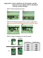
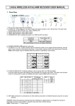
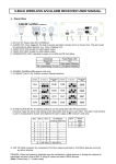
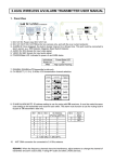
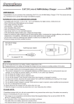
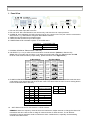
2.4GHz WIRELESS A/V/ALARM TRANSMITTER USER MANUAL
1. Panel View
1.
2.
3.
4.
5.
6.
1
2
3
4
5
6
7
8
9
10
○
○
○
○
○
○
○
○
○
○
DC+12V IN: Power input DC+12V/1.5A.
DC+12V OUT: DC+12V/750mA for box camera only, and with the over current protector.
ALARM IN: Once triggered, the built-in buzzer rings on for a 20-sec time. This port could be connected to
alarm sensor, e.g.: PIR Detector, Magnetic Reed Switch Detector.
AUDIO IN: RCA female for input audio signal.
VIDEO IN: BNC female for input video signal.
POWER/State LED: Indicated to power on and ARM status.
Indications
Power On
ARM
Power/State LED
On
High speed Flashing
7. DISARM: DISARM at TX transmitter’s side only.
8. CH SELECT (1 2 3 4): 2.4GHz 4-CH transmission channel selection.[Default: In-Band 4-CH]
(Note: Only one mode work at a time. If you want to use out-band mode, the TX transmitter and RX
receiver must made the same jumper setting, please reference to the Appendix A.)
In-Band Mode
Out-Band Mode
9. ID AND ALARM MUTE: ID address setting is use for paring with RX receivers. It must be make the same
code setting to link transmitter and receiver each other. The alarm mute function is use for muting built-in
buzzer at TX transmitter’s side only.
Bit 1
0
0
0
0
1
1
1
1
10.
Bit 2
Bit 3
ID Address
(Pairing with RX)
0
0
0
0
1
1
1
0
2
1
1
3
0
0
4
0
1
5
1
0
6
1
1
7
(1 = SW ON, 0 = SW OFF)
Bit 4
0
1
Alarm
Mute
ON
OFF
ANT: SMA connector for connected to 2.4 GHz antenna.
REMARK: When the frequency channels have the interference, adjust antenna or change the channel of
transmitter and don’t close to 802.11 a/b/g AP router and other 2.4GHz devices, To use different
transmitting channel would be avoid to interference other 2.4GHz device, especially set transmitting
channel at out-band mode.
2. Caution for Installation
2.1 Be careful, never let any water in this equipment.
2.2 If necessary, use a soft cloth moistened with alcohol to wipe off the dust.
2.3 Be extra careful not to shake the unit.
2.4 Avoid places where temperatures exceed 50 o C or higher.
2.5 Avoid places where there are frequent vibrations or shocks.
2.6 When any abnormalities occur, make sure to unplug the unit and contact your local dealer.
3. Packing
3.1 Transmitter
3.2 Antenna
3.3 User manual
3.4 Screws
3.5 Plastic-Conical-Anchor
3.6 Power Adaptor
×1
×1
×1
×4
×4
×1 [Option]
4. Specification
In-Band
CH1
CH2
CH3
CH4
4-CH 2414 MHz 2432 MHz 2450 MHz 2468 MHz
Out-Band
CH1’
CH2’
CH3’
CH4’
4-CH 2490 MHz 2510 MHz 2390 MHz 2370 MHz
RF IMPEDANCE
50 Ω Typical
POWER SUPPLY
DC12V/1.5A Adaptor
CURRENT CONSUMPTION
350mA Typical , Start-up current 650mA ( DC12V Input)
DC OUTPUT
DC12V/750mA
RF OUTPUT POWER
1.0 W
VIDEOINTPUT
1.0 Vp-p Composite @ 75Ω
AUDIO INPUT
2.0 Vp-p Typical, 2.7 Vp-p Max. @ 600Ω
ALARM INPUT
TTL/CMOS (Level Detection)
DIMENSIONS (without Antenna) L:86 mm
H:30 mm
D:110 mm
CHANNAL/ FREQUENCY
Q2010/05/17
Appendix A: How to Shift the TX Transmitter and RX
Receiver from In-Band 4-CH to Out-Band
4-CH by Jumper Setting.
STEP 1: Unscrew back-panel screws.
TX
RX
STEP 2: Pull the board outside and you can see a jumper there.
(Note: Don’t pull too much. Same as the picture bellow is good.)
RX
TX
STEP 3: Jumper configuration for 2.4G TX and RX.
In-Band
Out-Band
TX
In-Band Mode
In-Band
RX
Out-Band
Out-Band Mode