1
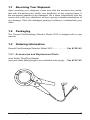
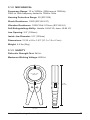
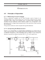
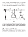
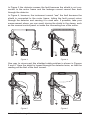
■
GROUND FAULT/LEAKAGE
DETECTOR
ENGLISH
User Manual
2610
TABLE OF CONTENTS
1. INTRODUCTION ..............................................................2
1.1 Receiving Your Shipment..........................................................3
1.2 Packaging .................................................................................3
1.3 Ordering Information.................................................................3
1.3.1 Accessories and Replacement Parts............................3
2. PRODUCT FEATURES .....................................................4
2.1 Description................................................................................4
2.2 Compatibility .............................................................................5
3. SPECIFICATIONS ............................................................6
3.1 Specifications............................................................................6
3.1.1 Electrical .......................................................................6
3.1.2 Mechanical....................................................................7
3.1.3 Safety............................................................................7
4. OPERATION ....................................................................8
4.1 Principle of Operation ...............................................................8
4.1.1 Measuring Current Leakage .........................................8
4.1.2 Interpreting the Measurement.......................................8
4.2 Equipment Troubleshooting ....................................................10
4.3 Testing Various Cable Configurations..................................... 11
4.3.1 Metal Conduits ............................................................ 11
4.3.2 Grounded Neutral .......................................................12
4.3.3 Neutral Grounded Through an Impedance .................13
4.4 Commonly Asked Questions...................................................13
5. MAINTENANCE .............................................................14
5.1 Cleaning..................................................................................14
Repair and Calibration...........................................................................15
Technical and Sales Assistance ............................................................15
Limited Warranty ...................................................................................16
Warranty Repairs...................................................................................16
CHAPTER 1
INTRODUCTION
Warning
These safety warnings are provided to ensure the safety of personnel and proper operation of the instrument.
• Never use this clamp on conductors with a voltage potential above
600Vrms.
• Never clamp around a conductor unless the clamp is terminated to
a measuring instrument of the proper input impedance.
• Keep the jaw contacts clean. If necessary, use a slightly oiled cloth
to remove oxidation.
• Ensure that the cable or bus bar is properly centered within the
clamp jaws.
• Keep away from other conductors which may create interference.
• Avoid leaving the clamp in damp places or exposing it to running
water.
• Due to shock or fire hazards, electrical connections of the instrument should be performed only by qualified personnel and in
accordance with local, state, and federal electrical requirements.
International Electrical Symbols
This symbol signifies that the instrument is protected by double or
reinforced insulation. Use only specified replacement parts when
servicing the instrument.
This symbol on the instrument indicates a WARNING and that the
operator must refer to the user manual for instructions before operating the instrument. In this manual, the symbol preceding instructions indicates that if the instructions are not followed, bodily injury,
installation/sample and product damage may result.
Risk of electric shock. The voltage at the parts marked with this
symbol may be dangerous.
2
Ground Fault/Leakage Detector Model 2610
1.1
Receiving Your Shipment
Upon receiving your shipment, make sure that the contents are consistent with the packing list. Notify your distributor of any missing items. If
the equipment appears to be damaged, file a claim immediately with the
carrier and notify your distributor at once, giving a detailed description of
any damage. Save the damaged packing container to substantiate your
claim.
1.2
Packaging
The Ground Fault/Leakage Detector Model 2610 is shipped with a user
manual.
1.3
Ordering Information
Ground Fault/Leakage Detector Model 2610 ...................... Cat. #1201.42
1.3.1 Accessories and Replacement Parts
4mm Safety Plug/Plug Adapter
(converts male safety plugs to non-shielded male plugs) ... Cat. #1017.45
Ground Fault/Leakage Detector Model 2610
3
CHAPTER 2
PRODUCT FEATURES
2.1
Description
The Model 2610 measures leakage current shunted to ground caused by
insulation faults. It enables the operator to locate failures when or before
they occur, without shutting down equipment or spending hours troubleshooting.
It is designed specifically for locating low current faults on high current
loads. The detector is a sensitive nickel alloy AC current transformer
capable of measuring differential or leakage current from 500µA, and may
be used to measure current up to 200A continuous duty (400A max).
The Model 2610 provides, on two ranges, 1mV/mAAC or 1mV/AAC. The
output leads are terminated with standard 4mm banana plugs capable of
interfacing with any standard multimeter.
Use of a digital multimeter with analog bar graph is recommended:
Digital to provide the proper voltage input impedance, and an analog bar
graph to track trends.
When the 2610 is used as a current leakage detector, it makes no
difference if the system is single-phase or poly-phase, or if the currents
are in-phase or out of phase, balanced or unbalanced.
The net magnetic field at any instant in time will be zero if all the conductors
surrounded by the current leakage detector are supplying all the current
delivered to and received from the load.
If any current is diverted through any alternate path, such as an insulation
breakdown to ground, the net loss will be detected producing a output
proportional to the amplitude of the fault current.
The Model 2610 may also be used simply as a highly accurate clamp-on
current probe. With its 4” jaw opening and range of 500µA to 200A, the 2610
provides a versatile way to analyze unbalanced current measurements,
leakage values on grounding conductors and ground loop currents.
4
Ground Fault/Leakage Detector Model 2610
2.2
Compatibility
The Model 2610 is compatible with any DMM, voltmeter, or other voltage
measuring instrument with the following features:
•
Range and resolution capable of displaying 1mVAC of input.
•
Voltmeter accuracy (uncertainty) of 0.75% or better to take full
advantage of the accuracy of the probe.
•
Minimum input impedance of 1MΩ on the 4A range or 1kΩ on
the 200A range.
Connect the probe to the multimeter or other instrument.
Select the appropriate AC voltage range on your multimeter.
The Model 2610 has two selectable output ranges. The 4A range will
produce a mV/mA with an output of 4VAC at 4A. The 200A range produces
1mV/A with 200mV at 200A.
Warning: User Safety
Always use a DMM, voltmeter or other displaying device, appropriately
rated for safety.
Ground Fault/Leakage Detector Model 2610
5
CHAPTER 3
SPECIFICATIONS
3.1
Specifications
3.1.1 ELECTRICAL
4A Range
Current Range: 500µA to 4AAC
Output Signal: 1mV/mA (4V max)
Accuracy*:
500µA to 10mA: 3% of Reading + 1mA
10mA to 4A: 0.5% of Reading + 0.5mA
Load Impedance: 1MΩ min
200A Range
Current Range: 500mA to 200AAC
(Between 200A and 400A, the max measurement time is 5 minutes with
20 minutes rest, @ 25°C [77°F] or less)
Output Signal: 1mV/A (400mV max)
Accuracy*:
0.5A to 10A: 0.5% of Reading + 0.5mA
10A to 200A: 0.5% of Reading + 0.5mA
200A to 400A: 0.5% of Reading + 1mA
Load Impedance: 1kΩ min
*Reference Conditions: Ambient temperature 23°C + 3°C, current frequency 48 to 65Hz,
impedance of measuring instrument >10MΩ/100pF, absence of DC current in the conductor,
conductor centered within the jaws.
6
Ground Fault/Leakage Detector Model 2610
3.1.2 MECHANICAL
Frequency Range: 10 to 1000Hz (100A max at 1000Hz);
30Hz to 1kHz frequency limited to 100A to 1kHz
Housing Protection Range: 20 (IEC 529)
Shock Resistance: 100G (IEC 68-2-27)
Vibration Resistance: 10/55/10Hz 0.15mm (IEC 68-2-6)
Self-Extinguishing Ability: Handle: UL94 V0; Jaws: UL94 V2
Jaw Opening: 3.9” (100mm)
Inside Jaw Diameter: 3.9” (100mm)
Dimensions: 12.25 x 5.9 x 1.63” (31.1 x 15 x 4.1cm)
Weight: 4.4 lbs (2kg)
3.1.3 SAFETY
Dielectric Strength Test: 2kVAC
Maximum Working Voltage: 600VAC
��������������
��������
������
��������
�
�
�
���������
�����
��������
Ground Fault/Leakage Detector Model 2610
�����
�������
7
CHAPTER 4
OPERATION
4.1
Principle of Operation
4.1.1 Measuring Current Leakage
When a generator supplies an AC load through a pair of wires in an
insulated cable, the current going out on one wire is equal to the current
returning; their vector sum equals zero. A ground fault changes this
equality, and the leakage current detector picks it up, measures it, and
provides an AC voltage output proportional to the severity of fault causing
the unbalance.
The ground conductor must not pass through the detector.
4.1.2 Interpreting the Measurement
Figure 1 is a schematic of a single-phase installation of a motor and an
oven, both grounded. The numbers indicate the amplitudes of the currents
in different conductors. This installation has no faults. If you clamp the
detector around the cables at points A,B,C or D, it will output zero.
�
�����
�
��
��
��
��
�
�
�
����
����
�
�
��
�����
��
��
����
���
���
Figure 1
8
Ground Fault/Leakage Detector Model 2610
In Figure 2, there is a fault in the installation. At point A, the Model 2610
detects 1A (the difference between 16A and 15A), indicating a fault downstream. At point C, it detects zero; therefore, the fault is not in the oven.
At points B and D, the detector picks up 1A, showing that the fault is in
the motor. If it gets worse, the leakage current will increase and the circuit breaker will trip. This motor should be disconnected immediately and
repaired.
�
�����
�
��
��
��
��
�
�
�
����
�
�
�
��
�����
��
�
��
�
���
���������������������
���
Figure 2
In a three-phase installation the principle is the same. But here it is necessary to pass all active conductors through the detector, including the neutral if one is used. If this is done properly, the detector output will be zero
if there is no current leaking to ground. If it detects something other than
zero, there is a ground fault that should be repaired.
4.2
Equipment Troubleshooting
To locate a fault quickly, begin your troubleshooting at the incoming lowvoltage distribution header. Successively check each feeder. If the Model
2610 detects a ground fault, follow the feeder downstream, branch by
branch, to the equipment with the problem.
Ground Fault/Leakage Detector Model 2610
9
It is useful to take measurements periodically to create a history of the
quality of the insulation. This is good preventive maintenance which could
prove valuable later. If you detect a fault current that is very low initially
but increases from day to day, this means that electrical failure is imminent and should be taken care of during the next planned maintenance
shutdown.
For best results, center the conductors within the clamp jaws. Check that
the edges of the jaws are perfectly clean and that they close tightly. Try to
avoid placing the conductors near the gaps, and group them as much as
possible.
If you are careless, you can affect the magnitude of the reading, depending on the current being carried in the conductors. In certain cases this
requires an interpretation. Normally, however, the absolute value of the
ground current is not important. All you need to know is whether the reading is zero.
4.3
Testing Various Cable Configurations
Older installations have a wide variety of electrical distribution systems.
Cables are clamped to walls and pass through metal conduits, and there
are many cases where a shielded cable was installed during revamping of
an area or addition to a building. If a cable is clamped to walls, detach it
and pull it away from the surface at several points, so the clamp can surround all the conductors.
4.3.1 Metal Conduits
Cables enclosed in metal conduits which are grounded are not a problem.
Simply apply the clamp around the conduit; the metal tube will not block
the measurement. Cables with a metal shield can be handled in the same
way as cable in metal conduit.
A grounded shield may present a problem. If it is a simple metal shield, like
a thin metal wrapping, it can be considered in the same way as the metal
conduit. If the armor is grounded by a conductor, it may be an inconvenience, depending on the terminal connections, as well as on the number
and type of ground connections along the cable.
10
Ground Fault/Leakage Detector Model 2610
In Figure 3 the detector senses the fault because the shield is not connected to the motor frame and the leakage current cannot flow back
through the detector.
In Figure 4, however, the instrument cannot “see” the fault because the
shield is connected to the motor frame, letting the fault current return
through the detector and causing it to read zero. If possible, take your
measurement where you can avoid closing the shield in the clamp, such
as the nearest control panel or inside the connecting box of the motor.
Figure 3
Figure 4
One way to circumvent this shielded cable problem is shown in Figures
5 and 6. Here the shield is looped through the detector twice, so that the
reading will be that of the fault current.
Figure 5
Ground Fault/Leakage Detector Model 2610
Figure 6
11
4.3.2 Grounded Neutral
It is easy to take measurements on this type of network, where major
faults trip the circuit breaker. Here, the detector can sense minor faults,
so repairs can be made before the problem gets worse. The inspection
method is the same as for a single-phase installation. Remember that on
a three-phase network, the currents add according to the vector sum law.
The Model 2610 measures the vector sum of the enclosed currents. If you
have, for example, a 400mA fault and a 250mA fault on the same phase,
the Model 2610 will detect 650mA. But if the two faults are on different
phases, they add vectorially and may even sum up to zero.
Figure 7 shows an example in which there are two separate faults:
400mA on a machine in one shop, 250mA on a machine in another shop.
The vector sum is not 650mA, but 350mA. If you switch off the machine
with the 250mA fault, the reading increases, indicating faults on different
phases.
4.3.3 Neutral Grounded Through an Impedance
Follow the procedure the same way as for a grounded neutral installation,
but with care. When the neutral is grounded through an impedance, a fault
(even a serious one) may not trip the circuit breaker, and the shop will
keep operating.
4.4
Commonly Asked Questions
Q. I have found an indication of 40 to 50mA on one of the main feeders with 300A on the line. Is this value a fault?
A. With 300A on the line, it is possible to find an undesired current of that
magnitude. Different cables in the installation may not have equivalent
capacitance and resistance. These cables provide for high current and,
of course, we apply a high current. Therefore, we may have a capacitive
influence which corresponds to 45mA.
Q. Must the conductors be centered within the jaws?
A. You should avoid placing the conductors close against the magnetic
circuit near the gaps, and should group the conductors as much as possible. You must also ensure that the jaw ends are perfectly clean and that
nothing prevents them from closing tightly.
12
Ground Fault/Leakage Detector Model 2610
Q. Is it possible when checking cables which run parallel, yet supply
the same load, to clamp the detector over each cable separately?
A. When there are parallel cables, the measurement is valid only if the
detector covers the cables together. In fact, if you take each one separately, it is highly probable that the distribution of current in the parallel
cables is not even. These differences can be caused by the fact that the
cables may not have exactly the same resistance.
Q. I have detected faults of 400mA and 250mA on branch circuits
being supplied by the feeder. But clamping onto the incoming feeder
resulted in an indication of 350mA. Can you explain why 400mA +
250mA = 350mA?
A. The detector measures residual current; in other words, the vectorial
sum of the currents. If you have a 400mA fault and a 250mA fault on the
same phase, you have every chance of finding 650mA. But, if you have
two faults on different phases, they add as vectors. In a very favorable
theoretical case, we could even find zero.
Q. The Model 2610 detects faults caused by insulation failures. How
does detecting faults with the detector differ from information resulting from megohmmeter insulation tests?
A. The Model 2610 will detect electrical faults while the equipment is still
in operation. This offers two distinct advantages. First, it is not necessary
to shut the equipment down, eliminating costly down time; and second,
you may detect faults that would not be evident under static conditions.
Q. Would it be possible to clamp the Model 2610 directly around the
grounding detector?
A. Yes, in some instances it may be possible to detect fault current on a
specific motor if there is a dedicated grounding path. However, if several
devices are sharing a common ground, it should be noted that the fault
may be occurring on any one of the devices.
Ground Fault/Leakage Detector Model 2610
13
CHAPTER 5
MAINTENANCE
WARNING:
•
For maintenance use only specified replacement parts.
•
To avoid electrical shock, do not attempt to perform any servicing unless you are qualified to do so.
•
To avoid electrical shock and/or damage to the instrument, do
not get water or other foreign agents into the case. Turn the
instrument OFF and disconnect the unit from all the circuits
before opening the case.
5.1
14
Cleaning
•
Wipe the case and jaw covers with a lightly moistened cloth and
mild detergent.
•
Do not use any abrasives or solvents.
•
If rusted, the jaw mating surfaces of the Model 2610 may be
lightly sanded with very fine sandpaper and then very lightly
oiled. Wipe off excess oil and do not let it drip into the case.
Ground Fault/Leakage Detector Model 2610
Repair and Calibration
To ensure that your instrument meets factory specifications, we recommend
that it be submitted to our factory Service Center at one-year intervals for recalibration, or as required by other standards or internal procedures.
For instrument repair and calibration:
You must contact our Service Center for a Customer Service Authorization
Number (CSA#). This will ensure that when your instrument arrives, it will be
tracked and processed promptly. Please write the CSA# on the outside of the
shipping container. If the instrument is returned for calibration, we need to
know if you want a standard calibration, or a calibration traceable to N.I.S.T.
(Includes calibration certificate plus recorded calibration data).
Chauvin Arnoux®, Inc.
d.b.a. AEMC® Instruments
15 Faraday Drive
Dover, NH 03820 USA
Tel: (800) 945-2362 (Ext. 360)
(603) 749-6434 (Ext. 360)
Fax: (603) 742-2346 or (603) 749-6309
[email protected]
(Or contact your authorized distributor)
Costs for repair, standard calibration, and calibration traceable to N.I.S.T. are
available.
NOTE: All customers must obtain a CSA# before returning any
instrument.
Technical and Sales Assistance
If you are experiencing any technical problems, or require any assistance with
the proper operation or application of your instrument, please call, mail, fax or
e-mail our technical support hotline:
Chauvin Arnoux®, Inc.
d.b.a. AEMC® Instruments
200 Foxborough Boulevard
Foxborough, MA 02035, USA
Phone: (800) 343-1391
(508) 698-2115
Fax:
(508) 698-2118
[email protected]
www.aemc.com
NOTE: Do not ship Instruments to our Foxborough, MA address.
Ground Fault/Leakage Detector Model 2610
15
Limited Warranty
The Model 2610 is warranted to the owner for a period of one year from
the date of original purchase against defects in manufacture. This limited
warranty is given by AEMC® Instruments, not by the distributor from whom
it was purchased. This warranty is void if the unit has been tampered
with, abused or if the defect is related to service not performed by AEMC®
Instruments.
For full and detailed warranty coverage, please read the Warranty Coverage Information, which is attached to the Warranty Registration Card
(if enclosed) or is available at www.aemc.com. Please keep the Warranty Coverage Information with your records.
What AEMC® Instruments will do:
If a malfunction occurs within the one-year period, you may return the
instrument to us for repair, provided we have your warranty registration
information on file or a proof of purchase. AEMC® Instruments will, at its
option, repair or replace the faulty material.
REGISTER ONLINE AT:
www.aemc.com
Warranty Repairs
What you must do to return an Instrument for Warranty Repair:
First, request a Customer Service Authorization Number (CSA#) by phone
or by fax from our Service Department (see address below), then return the
instrument along with the signed CSA Form. Please write the CSA# on the
outside of the shipping container. Return the instrument, postage or shipment
pre-paid to:
Chauvin Arnoux®, Inc. d.b.a. AEMC® Instruments
Service Department
15 Faraday Drive • Dover, NH 03820 USA
Tel: (800) 945-2362 (Ext. 360)
(603) 749-6434 (Ext. 360)
Fax: (603) 742-2346 or (603) 749-6309
[email protected]
Caution: To protect yourself against in-transit loss, we recommend you
insure your returned material.
NOTE: All customers must obtain a CSA# before returning any
instrument.
16
Ground Fault/Leakage Detector Model 2610
12/03
99-MAN 100088 v3
Chauvin Arnoux®, Inc. d.b.a. AEMC® Instruments
15 Faraday Drive • Dover, NH 03820 USA • Phone: (603) 749-6434 • Fax: (603) 742-2346