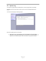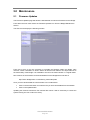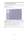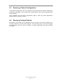
1
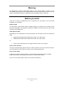
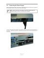
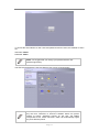
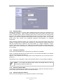
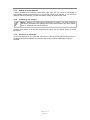
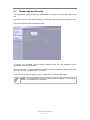
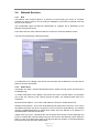
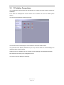
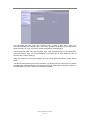
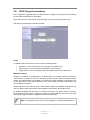
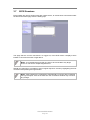
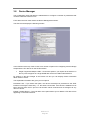
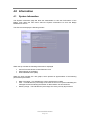
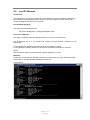
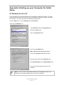
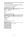
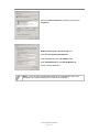
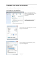
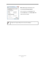
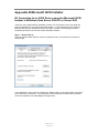
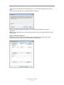
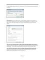
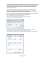
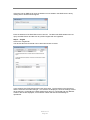
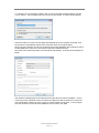
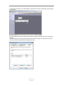
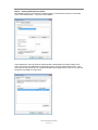
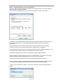
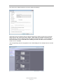
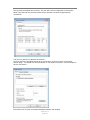
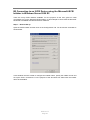
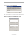
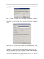
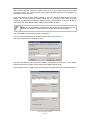
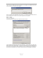
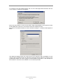
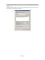
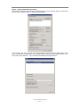
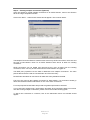
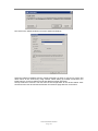
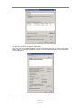
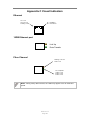
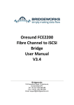
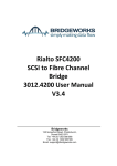
Oresund EFC102200 iSCSI to FC Bridge User Manual V1.1 Bridgeworks 135 Somerford Road, Christchurch, Dorset BH23 3PY Tel: +44 (0) 1202 588 588 Fax: +44 (0) 1202 588 589 Email: [email protected] Manual Revision History Revision Date Firmware 1.0 November 2012 V3_04 AP 1.1 October 2013 V3_04 AP iSCSI to FC Page 2 Warning The Bridgeworks Oresund EFC102200 iSCSI to fibre channel Bridge contains no user serviceable components. Only an Authorized Service Centre should carry out any servicing or repairs. Unauthorized repairs or modifications will immediately void your warranty. Before you start There are a number of additional pieces of equipment you will require for the successful installation of your Bridge: Ethernet Cable You will require a good quality cable of suitable length to go between your network access point and the Bridge. This should be marked as certified to Cat 5e and have a RJ45 style connector at the Bridge end. 10Gb Ethernet Cable Depending on the configuration you have purchased you will require at least one cable from either Multimode Multi Mode 50/125 OM3 Patch Cable, up to 300 meters. Multimode Multi Mode 50/125 OM4 Patch Cable, up to 550 meters. A SFP+ Direct Attached Twin-Ax Copper interface cable, up to 5 meters. Or Fibre Channel Interface The Fibre Channel Bridge supports the use of SFP modules to connect to the Fibre Channel. You will require the correct type to connect to your existing infrastructure. Fibre Channel Cable In addition to the fibre channel interface, you will require a good quality cable of suitable length to go between your Bridge and your device or fibre channel switch. If you are in any doubt, please contact your reseller for assistance. Oresund EFC102200 Page 3 Table of Contents 1.0 Introduction 5 1.1 Overview ...................................................................................................................5 1.2 Manual Layout ...........................................................................................................6 1.3 Definitions ..................................................................................................................6 1.4 Safety Notices ...........................................................................................................7 2.0 Installing the EFC102200 Bridge ...................................................................................8 2.1 Connecting the Ethernet Interface ............................................................................8 2.2 Connecting the 10Gb Ethernet Cables .....................................................................9 2.2 Connecting the Fibre Channel Interface ................................................................ 11 2.3 Connecting the Power Supply ................................................................................ 12 3.0 Configuring the EFC102200 Bridge............................................................................ 13 3.1 Using the Web Interface ......................................................................................... 13 3.1.1 Browsers ........................................................................................................ 13 3.1.2 Connecting to the Web Interface ................................................................... 13 3.2 Configuring the Network Parameters ..................................................................... 16 3.2.1 Setting the Hostname ........................................................................................ 16 3.2.2 Enabling IPv6 ..................................................................................................... 16 3.2.3 Setting the MTU ................................................................................................. 17 3.2.4 Setting the IP Address ....................................................................................... 17 3.2.5 Setting the Subnet Mask .................................................................................... 17 3.2.6 Setting the Gateway Address ............................................................................ 17 3.2.7 Setting an IPv6 IP Address ................................................................................ 18 3.2.8 Committing the changes .................................................................................... 18 3.2.9 Reconnect to the Bridge .................................................................................... 18 3.3 Passwords and Security ......................................................................................... 19 3.4 Network Services ................................................................................................... 20 3.4.1 NTP .................................................................................................................... 20 3.4.2 Email Alerts ........................................................................................................ 20 3.4.3 iSNS ................................................................................................................... 21 3.5 FC Initiator Connections ......................................................................................... 22 3.6 iSCSI Target Connections ...................................................................................... 24 3.7 iSCSI Sessions ....................................................................................................... 25 3.8 Device Manager ..................................................................................................... 26 4.0 Information .................................................................................................................. 27 4.1 System Information ................................................................................................ 27 4.2 System Log ............................................................................................................ 28 5.0 Maintenance ............................................................................................................... 29 5.1 Firmware Updates .................................................................................................. 29 5.2 Saving the Configuration to Disk ............................................................................ 30 5.3 Restoring A Saved Configuration ........................................................................... 31 5.4 Restoring Factory Defaults ..................................................................................... 31 6.0 Trouble shooting ......................................................................................................... 32 6.1 Lost Password ........................................................................................................ 32 6.2 Network problems .................................................................................................. 33 6.3 Device related problems ........................................................................................ 34 6.4 Poor Performance .................................................................................................. 35 6.5 Lost IP Address ...................................................................................................... 36 Appendix A Setting up your Computer for Initial Setup ........................................................... 37 A1 Windows 95, 98 or NT ................................................................................................... 37 A2 Windows 2000, 2003, XP .............................................................................................. 38 A3 Windows Vista / Server 2008 or Vista or 7 .................................................................... 40 Appendix B Microsoft iSCSI Initiator ........................................................................................ 42 B1 Connecting to an iSCSI Device using the Microsoft iSCSI Initiator in Windows Vista Server 2008 R1 or Server 2003 .......................................................................................... 42 B2 Connecting to an iSCSI Device using the Microsoft iSCSI Initiator in Windows Server 2008 R2 ............................................................................................................................... 54 Appendix C Visual Indicators ................................................................................................... 66 Appendix D Technical Specifications ...................................................................................... 67 iSCSI to FC Page 4 1.0 Introduction Thank you for purchasing the Bridgeworks iSCSI to fibre channel Bridge. The Bridge has been designed to ensure that in the majority of installations it will require the minimum of set up before use. However, we suggest you read the following section that will guide you through setting up both the network and fibre channel aspects of the iSCSI Bridge The GUI Management section guide you through the initial set up required to install the Bridge on to your network. 1.1 Overview The Fibre Channel Bridge creates an interface between a network, which utilises the Fibre Channel protocol, and iSCSI devices that reside upon the Ethernet network. The internal circuitry of the Bridge acts as a two-way interface converting the data packets that are received on the Fibre Channel network to iSCSI data packets ready for transporting these across a network to iSCSI enabled storage devices such as disks, tape drives. The Bridgeworks Enterprise iSCSI Bridge Oresund EFC102200 Page 5 1.2 Manual Layout Throughout the manual symbols will be used to quickly identify different pieces of information. This icon represents a note of interest about a step or section of information. This icon represents an important piece of information. This icon represents a warning, care must be taken and the warning should be read thoroughly. 1.3 Definitions In order to understand the process of identifying and configuring devices on the SCSI bus for the Server to communicate with it is necessary to understand some of the terms used by the menus. iSCSI Target Device iSCSI target devices are devices such as disk drives, tape drives or RAID controllers that are attached to the network. Each device is identified by an IQN – iSCSI Qualified Name. iSCSI Qualified Name (IQN) Anything connected to a network, be it a computer, printer or iSCSI device must have a unique identifier, such as an IP address, to enable other devices to communicate with it. With iSCSI devices (both targets and initiators) an extra level of identification in addition to the IP address is employed. This is called the IQN. The IQN includes the iSCSI Target’s name and an identifier for the shared iSCSI device. Example: 2002-12.com.4bridgeworks.sdt600a014d10: 5 CHAP CHAP is an authentication scheme used by Servers to validate the identity of clients and vice versa. When CHAP is enabled, the initiator must send the correct Username and Target Password to gain access to the iSCSI Bridge. The Initiator Secret is provided to allow iSCSI mutual CHAP. If mutual CHAP is selected on the Initiator, the iSCSI Bridge will authenticate itself with the initiator using the initiator secret SCSI Target Device A SCSI device is a device that is connected to the SCSI bus that can be accessed by the Server. Each device on the SCSI bus has a Unique ID number in the range 0-15. Note: By convention, ID 7 on the SCSI Bus is reserved by the Server’s Host Bus Adaptor. Logical Unit Numbers (LUN) Each SCSI device on the SCSI bus can support sub-devices. These are called LUNs. Within the iSCSI Connect Bridge each SCSI ID on the SCSI bus can support 7 LUNs. iSCSI to FC Page 6 1.4 Safety Notices This device should only be installed by suitably trained personnel. Protection provided by the equipment may be impaired if used in a manner not specified by the manufacturer. Do not block the enclosure’s vents. Air enters from the front and is exhausted out the back of the device. This device is connected to the AC power line. Before using the device, please read the instructions carefully, in order to use the device correctly and safely. For the installation instructions, refer to the installation section of this guide. Class I Equipment. This equipment must be earthed. The power plug must be connected to a properly wired earth ground socket outlet. An improperly wired socket outlet could place hazardous voltages on accessible metal parts. Do not attempt to service the equipment yourself, doing so will void the warranty and may damage the system. This unit contains hazardous voltages and should only be opened by a trained and qualified technician. To prevent electric shock, do not remove the cover. There are no user-serviceable parts inside. The power cord is used as a disconnection device. To de-energize the equipment, disconnect the power cord. Do not use the equipment where it can get wet. Protect equipment from liquid intrusion. If your equipment gets wet, disconnect power to the equipment and to any attached devices. If the Bridge is connected to an electrical outlet, turn off the AC power at the circuit breaker before attempting to remove the power cables from the electrical outlet. Disconnect any attached devices. Use only the power supply cord set provided with the system for this unit, should this not be correct for your geographical area, please contact your supplier. The mains plug to the rear of the unit is used as the power disconnect device, please ensure that this is kept clear from any obstruction and is visible at all times. Before installing or removing signal cables, ensure that the power cables for the system unit and all attached devices are unplugged. To prevent electrical shock hazard, disconnect the power cable from the electrical outlet before relocating the system. Class 1 Laser Product: Certain models will use a Small Form Factor Pluggable GBIC module for connection to an optical network. These devices may use a Class 1 Laser device – it is important that you do not stare into the Laser beam. Oresund EFC102200 Page 7 2.0 Installing the EFC102200 Bridge There are 4 basic steps to installing the iSCSI Bridge 2.1 Connecting the Ethernet cables Connecting the 10Gb Ethernet cables Connecting the Fibre Channel Interface Connecting the Power Supply Connecting the Ethernet Interface The iSCSI Bridge can be used on the following network configurations: 10BaseT 100BaseT 1000BaseT (Gigabit) It is not necessary to specify which network type you are connected to, as the iSCSI Bridge when powered up it will automatically select the correct network speed. The connection to the management Ethernet network is via an industry standard twisted pair, RJ45 copper interface on the front of the unit. To connect the iSCSI Bridge to the Ethernet network, inset one or two Cat 5E cables into the connector on the unit as shown below. When the plug is in the correct position a “click” should be heard. Note: If you only intend to use a single network connection, use the left-hand network socket (Management A) as this is set to 10.10.10.10 for the initial configuration of the Bridge. Rear Panel of the Bridge Showing Ethernet Cable Connections iSCSI to FC Page 8 2.2 Connecting the 10Gb Ethernet Cables Depending on the configuration you have purchased one of two cables will be required for your product. Small Form-factor Pluggable (SFP) If you have purchased the card with the SFP’s already connected the following cables can be used Multimode Multi Mode 50/125 OM3 Patch Cables up to 300 meters Multimode Multi Mode 50/125 OM4 Patch Cables up to 550 meters To connect the iSCSI Bridge the Ethernet network or directly to a device, insert one or two SFPS into the unit. Insert the multimode cables into the SFP you just inserted on the unit as shown below. When the plug is in the correct position a “click” should be heard. Oresund EFC102200 Page 9 Using a copper solution If you are using a copper based solution, a SFP+ Direct Attached Twin-Ax Copper interface cable must be used. The maximum supported length of which is 5 meters. To connect the iSCSI directly to a device, inset one or two SFP+ cables into the connector on the unit as shown below. When the plug is in the correct position a “click” should be heard. Note: The 10Gb Ethernet ports only support speeds of 10GB/Sec. iSCSI to FC Page 10 2.2 Connecting the Fibre Channel Interface The Node can be used on the following Fiber configurations with an 8 GB card 2GB 4GB 8GB The 4GB card can support the following speeds 1GB 2GB 4GB It is not necessary to specify which link speed you are using as the Node will automatically negotiate the best speed when first powered up. With the 8GB card The connection to the FC network is via an industry Small Form-factor Pluggable (SFP) interface Module that is inserted into the SFP receptacle on the front of the unit. Rear Panel of the Node Showing FC Cable Connections Note: Only use an SFP that meet or exceed the following standards: EU: IEC/EN 60825-1, North America: FCC, CDRH The 4 GB cards have the sfps connected to the hardware and cannot be replaced. Oresund EFC102200 Page 11 2.3 Connecting the Power Supply Before connecting the power cord to the unit, ensure the wall plug is removed or is switched off. Connect the power cord to the rear of the iSCSI Bridge. Note: Before powering up the Bridge, ensure all the peripherals are powered up and you have a connection to the network. To turn on the Node use the switch on the opposite side to the power connector and push in the button. Whenever the Node is powered on the green LED on the back panel will be illuminated. iSCSI to FC Page 12 3.0 Configuring the EFC102200 Bridge Before the iSCSI Bridge can be used on the network for the first time, it is necessary to configure a number of parameters. 3.1 Using the Web Interface Now that the Bridge is fully connected the primary method for configuring any option is through its web interface. The following section highlights the requirements needed to access these pages and the consistent layout used throughout. Note: The default IP address of the web interface for the Bridge is http://10.10.10.10/ 3.1.1 Browsers This Bridge supports the following browsers Microsoft Internet Explorer 7 Microsoft Internet Explorer 8 Microsoft Internet Explorer 9 Mozilla Firefox 9 Mozilla Firefox 10 Google Chrome Latest Note: JavaScript must be enabled within the web browser to use the web interfaces functionality. Important: If you choose to use a browser that is not on the list of supported browsers Bridgeworks cannot guarantee the behaviour of the Nodes functionality. 3.1.2 Connecting to the Web Interface From within your web browser, connect to the Bridge using the address http://10.10.10.10/ (or, if you have changed this previously, the address of the left-hand network port). Depending on your current network parameters, it may be necessary to change your network settings on your computer for the initial set up. See Appendix A for further help. Once you have connected to the web interface on the Bridge you will see the entry page shown below. Oresund EFC102200 Page 13 To access the web interface a user name and password must be used, the defaults of which are: Username: admin Password: admin Note: We suggest that you change your password at the next possible opportunity. The GUI will now display the Console Home menu screen as shown below. Note: For security reasons only one person can access this GUI at any one time. Therefore, to avoid the situation where one person forgets to logout, effectively locking up the GUI, the Bridge incorporates a five minute idle timer, which will automatically logout any user after this period. iSCSI to FC Page 14 Within the Support section there is a link that will open up your mail service with Bridgeworks’ Email address loaded and an Online Help button. The Online help is contextually aware of which GUI page you are currently viewing and will provide you with help relevant to the display and configuration data. Oresund EFC102200 Page 15 3.2 Configuring the Network Parameters Click on the Connections icon to enter the network configuration page. 3.2.1 Setting the Hostname In this box enter the name you wish to use to address this Bridge in the future. We suggest that you use a name that is relevant to its location and/or its purpose. Note: If you select the DHCP mode, ensure your DHCP server is set to automatically update the DNS server. 3.2.2 Enabling IPv6 Checking this box will enable the Bridge to use IPv6 IP addresses. As with Ipv4, you can either choose to use DHCP or assign a static IPv6 address. To change the settings of a specific connection, click on the connection. You will be presented with the screen as shown below where you can make changes to the connection. iSCSI to FC Page 16 3.2.3 Setting the MTU Enabling larger frames on a jumbo frame capable network can improve the performance of your backup operations. Jumbo frames are Ethernet frames that contain more than 1500 bytes of payload (MTU). Before enabling jumbo frames, ensure that all the devices/hosts located on the network support the jumbo frame size that you intend to use to connect to the Bridge. If you experience network related problems while using jumbo frames, use a smaller jumbo frame size. Consult your networking equipment documentation for additional instructions. Some networking switches require you to specify the size of the jumbo frame (MTU) when enabling, as opposed to a simple enable command. On these switches it might be required to add the necessary bytes needed for the frame header (i.e., header information + MTU). Typical header size is 28 bytes, so a 9000 byte MTU would translate to 9028 byte setting. Refer to your switch documentation to understand what the maximum frame size settings are for your switch. 3.2.4 Setting the IP Address There are two possibilities when configuring the IP address for the Bridge: DHCP - the Bridge will seek out the DHCP server on your network and obtain an IP address from the server each time it powers up. Static IP - the IP address set in this page will be the IP address the unit will use each time it powers up. Depending on your configuration, either click the DHCP button or set your Static IP address. Note: If you select the DHCP mode, ensure your DHCP server is set to automatically update the DNS server. 3.2.5 Setting the Subnet Mask If the Bridge is configured to use DHCP the net mask will be issued from the DHCP server. If you are using static IP address enter the IP mask in this box. 3.2.6 Setting the Gateway Address Enter in this box the address of your gateway controller for your network. Oresund EFC102200 Page 17 3.2.7 Setting an IPv6 IP Address If IPv6 is enabled on the network connections page, here you can choose to use DHCP to automatically assign an IPv6 address, or you can set a static IPv6 address. If you choose to assign a static IPv6 address, you will also need to assign an IPv6 subnet mask. 3.2.8 Committing the changes Note: Before you commit these parameters to memory, it is worth checking that all the parameters and spellings are correct and that these have been written down in a safe place for future reference. Click the save button to save these parameters and then click the reboot button in the left hand pane. 3.2.9 Reconnect to the Bridge If you made changes to your computer, return them to their previous setting and reconnect to the Bridge using the IP address or hostname, depending on which addressing mode you selected. iSCSI to FC Page 18 3.3 Passwords and Security This configuration page will allow the administrator to change the access password for the GUI. From within the main menu select the Password and Security icon under the Network section The GUI will now display the following window To change your password, type the existing password and the new password into the appropriate boxes and press save. Secure Connection – by clicking this box it will force all further transactions with the GUI to be done via a secure, encrypted HTTPS connection. Once you have clicked this option, save the configuration, logout and login again. Note: It is not possible to reset the password without logging into the GUI so ensure you remember your password! Oresund EFC102200 Page 19 3.4 Network Services 3.4.1 NTP The Network Time Protocol (NTP) is a protocol for synchronising the clocks of computer systems over the IP network. This is used by the Bridge to synchronise its internal clock with the rest of the network. This configuration page will allow the administrator to configure the IP addresses for the Network Time Domain server. From within the main menu select the Service Control icon under the Network section The GUI will now display the following window To enable NTP on the Bridge, click the tick box and enter the IP address for the NTP Server and then click the save button. 3.4.2 Email Alerts The Bridge can notify a systems administrator when certain level log events are observed in the Bridges logs. To enable email alerts on the Bridge, click the tick box next to “Enable Alerts”, this will allow you to alter the contents of the currently greyed out fields. The following fields need to be completed. Recipient Email Address - This is the email address to which the emails will be sent. Senders Email Address - This is the email address that emails will be sent from. This can be any address and does not have to be genuine, which is useful for email filtering. For example entering [email protected] would allow emails from this address to be filtered to a specified folder in the users email client. Trigger Event Log Level - This allows the user to specify what severity of event will trigger the log to be emailed with Critical Events being the most severe and Warning Events being the least. For each level picked the higher level logs will also be emailed, for example selecting Error Events will also send all Critical Events. iSCSI to FC Page 20 Below are examples of events that will be sent for each log level Critical: Error: Warning: The Bridge is running at non recommended temperatures The Bridge rejected a login attempt. An Initiator has logged out of the Bridge. 3.4.3 iSNS Internet Storage Name Service allows automated discovery, management and configuration of each iSCSI resource from a central point. If this option is enabled the Bridge will register its resources with a central iSNS server. To enable iSNS on the Bridge, click the tick box and enter the IP address for the iSNS Server and click the save button. . Oresund EFC102200 Page 21 3.5 FC Initiator Connections This configuration page will allow the administrator to configure the Fibre Channel Interface of the Bridge. From within the Management Console select the FC initiator icon from the SCSI System section. The GUI will now display the following window The left hand most icons display the current state of each Fibre Channel Port. The green/red arrow displays whether the port is up or down whilst the number displays the negotiated Fibre Channel speed. Clicking on the icon will take you into a further screen displaying more detailed information. Now select the first of the port’s configuration icons. The Screen will now display the following: iSCSI to FC Page 22 The link speed pull down menu has 4 options: Auto, 4 GB/s, 2 GB/s, and 1 GB/s. It is recommended that you leave the option set to Auto. However some SFP’s do not report their speed correctly, so if you are unsure, set the link speed to the SFP speed The topology pull down menu has 3 options: Auto, Loop (arbitrated Loop, FC-AL), and Pointto-Point (FC-P2P). Again the recommendation is you leave this as Auto unless you wish to force this into a known topology. When you click on the 'Connected Targets' icon you will be presented with the screen shown below. The default configuration type is set to Automatic. By changing this to manual you can enable or disable each individual target on the Fibre Channel link. Select the FC target by clicking on its World Wide Port name, and then click enable or disable. Oresund EFC102200 Page 23 3.6 iSCSI Target Connections This configuration page will allow the administrator to configure the password and username for the CHAP authorisation on the Bridge From within the main menu select the iSCSI Target icon from the SCSI System group The GUI will now display the following window CHAP To enable CHAP click the tick box and enter the following details Username – this is the same name as specified in the iSCSI host Initiator Secret – this is the password defined in the iSCSI host Target Secret - this is the password that the Bridge will send to the iSCSI host. Multipath Settings Multipath is a method of sending data to an iSCSI target over multiple network connections. These network connections can be on the same physical network cable or separate network cables. By using Multipath it is possible to increase the network bandwidth to send data over. A user may have a single iSCSI Session for an iSCSI Target, but within that session may have multiple connections. iSCSI uses to two main network ports, 3260 and 860. Within the Multipath configuration the user can specify which ports will be made available to the initiator, 860, 3260 or both. By default, the Bridge will allow up to 10 iSCSI connections per iSCSI Session. However, some initiators will only allow 1 iSCSI Connection per iSCSI Session and will reject any login to an iSCSI Target that tries to negotiate more iSCSI Connections. Note: See Appendix B for how to set up multipath on a Microsoft based Server. iSCSI to FC Page 24 3.7 iSCSI Sessions Each initiator will open a session with each target device; to review these connections select the iSCSI secessions page from the SCSI group. This page lists the current connections i.e. logged on, from iSCSI hosts. It displays which initiator is connected to which Target device. Note: It is possible that more than one host to be connected to any target device or one host to multiple target devices. Should it be required, it is possible to send a logout request to a host by highlighting the host connection and pressing the logout button. Note: Many initiators are configured to automatically reconnect after completing the logout request. If this is the case then the connections window may not show any change. Oresund EFC102200 Page 25 3.8 Device Manager This configuration page will allow the administrator to configure a number of parameters that control the behavior of the FC bus. From within the main menu select the Device Management section. The GUI will now display the following window In the first Box at the top of the screen are a number of options for configuring how the Bridge will present the FC devices on the SCSI interface. Single Target with Multiple LUNs – Choose this option if you require all the devices on the FC ports to appear as a single WWN with devices as LUNs underneath this. By clicking on the blue triangle in the Device info box you can display further information about each FC device. The expanded information also gives you two options Persistent LUN - if you select this option, the device will always be presented to the SCSI interface in exactly the same way – i.e. the same LUN number. If the device is disabled or has been removed from the FC port its LUN number will be reserved and not assigned to any other FC device. Enable / Disable Device – This pull down menu option allows you to disable a FC device from appearing on the SCSI interface. iSCSI to FC Page 26 4.0 Information 4.1 System Information This System Information page will allow the administrator to view the Performance of the Bridge. From within the main menu select the System Information icon from the Bridge Maintenance section. The GUI will now display the following window Within the top window the following information is displayed Current Firmware & Boot Loader Revision Level Serial Number of the Bridge iSCSI Qualified Name (IQN) Within the lower window are 3 bar graphs, which provide an approximation of the following performance parameters: Data Throughput - This indicates the current performance in MB/s. CPU - This indicates the percentage of the time the CPU is occupied undertaking the management and scheduling the transfer of data between the two interfaces Memory Usage - This indicates the percentage of memory used by all processes Oresund EFC102200 Page 27 4.2 System Log This System Log page allows the administrator to view the logged status of the Bridge. From within the main menu select the View Log-file icon from the Bridge Maintenance section. The GUI will now display the following window Below the log display pane are two options: Clear System Log – this will delete the current and saved logs within the Bridge Download – this will download the log file to your local disk. You may be asked by our support team to email this log file to them to aid them in any problem resolution. iSCSI to FC Page 28 5.0 Maintenance 5.1 Firmware Updates The Firmware Updates page will allow the administrator to load new firmware into the Bridge. From within the main menu select the Firmware Updates icon from the Bridge Maintenance section. The GUI will now display the following window. From time to time it may be necessary to upgrade the firmware within the Bridge. New versions contain resolutions to known issues as well as new features and improvements to the functionality of the Bridge. It is advisable to check for the latest release on a regular basis. New versions of the firmware can be downloaded from the Bridgeworks web site at: http://www.4bridgeworks.com/software_downloads.phtml Once you have downloaded the new firmware to a local disk drive: Click on the browse button to locate the file you have downloaded from the website. Click on the update button. Updating the firmware will take a few minutes after which it will be necessary to reboot the system to bring the new code into memory. Oresund EFC102200 Page 29 5.2 Saving the Configuration to Disk The Load/Save Configuration page will allow the administrator to save and load the configuration parameters to a file on a local disk. From within the main menu select the Load/Save Configuration icon from the Bridge Maintenance section. The GUI will now display the following window Once you have finished configuring your Bridge we recommend that you save your configuration data to a local disk. By doing so you could save valuable time if the unit requires replacement, or if you require restoring an old firmware version, as the configuration may change due to upgrades. It is possible to create a “Boiler Plate” configuration and load this into each new Bridge as it is initialised. This can ease the rollout of multiple Bridges within an enterprise. To save the configuration data click on the “Click here to Download” link from within the Export Configuration window located in the centre of the page. Depending on the browser you are using, select the option to save file to disk. The Bridge will now download an encoded file that contains all the configuration settings for the Bridge. iSCSI to FC Page 30 5.3 Restoring A Saved Configuration To reload the configuration, click on the Browse button and locate the required configuration to upload into the Bridge. Once located click the upload button and the new configuration data will be uploaded. Once completed, use the various configuration pages to make any further adjustments required and then reboot the system. 5.4 Restoring Factory Defaults By clicking on this button all the parameters will be set back to the factory defaults. This includes IP address, hostname and passwords. We recommend that if you return the Bridge for maintenance that you reset to defaults to protect passwords and other sensitive information Oresund EFC102200 Page 31 6.0 Trouble shooting 6.1 Lost Password If you have lost the admin password it is possible to reset it with help from Bridgeworks. First ensure that there is nothing entered into the user field and then type PASSWORDRESET into the password field. The unit will respond with a challenge key. Copy this key into an email along with your name, company and contact details – you must include your company’s personnel email address for security purposes. Send this email to [email protected] and a key will be returned for you to enter into the key field. Press the reset button once you have entered the key – this will reset the admin user password back to admin. iSCSI to FC Page 32 6.2 Network problems Under normal operation you should be able to “ping” the network address of the Bridge and receive a response. If this fails, run through the following checklist to help you identify the problem. Ensure that the Bridge is properly plugged into the library and that the library is powered on. Make sure that the power LED on the Bridge is illuminated. Ensure that the Ethernet cable is plugged in at both ends . Note the status of the LEDs positioned within the Ethernet connector – make sure that the “Link present” LED is illuminated. If it is not, check with your Network Administrator. If you are using a Bridge with two Ethernet ports and only one network cable, try using the other network address and/or the other network port. Ensure you are using the correct network address and netmask. Scan the network using the LAN Scan utility to find all the Bridges connected to the network in case the network address is different from that expected. See Section Lost IP Address. If none of the above resolves your problem, then after consulting with your Network Administrator, please contact support. Oresund EFC102200 Page 33 6.3 Device related problems Once the Bridge has booted and the target devices have finished initialising, these devices should be available on the host machine. After checking that you have correctly configured the initiator, run through the following checklist to help you identify the problem. Ensure that the devices are powered on and are ready – some libraries can take 5 minutes or more before they are ready and appear on the Bridge. (The power up status of libraries are usually displayed on the front panel). Ensure that the cables between the Bridge and the devices are connected. Connect to the Bridge via the GUI and check that devices are present in the Device management window and are enabled – you will need to drill down each device entry to see this option. If you can “ping” the Bridge but the GUI fails to appear check the setting within the Web Browser you are using. If you are directly connected to the Bridge then any proxy setting will require adjustment and may require you to contact your administrator. Ensure that the CHAP settings for the initiator and the Bridge are the same. A common mistake is when enabling CHAP only for a device after the initial discovery by the initiator. It will be necessary to remove the address from the discoveries tab and recreate it with the appropriate CHAP settings, otherwise any rediscoveries will be attempted without CHAP and no devices will be returned. Force a rediscovery from the initiator. Reboot the devices and Bridge. If none of the above resolves your problem, please contact support. iSCSI to FC Page 34 6.4 Poor Performance Poor performance can be caused by many differing reasons. The following checklist is provided as a guide to where you may find ways to improve performance. Ensure your initiator and Bridge are communicating at the fastest possible network speed. Within the GUI is the Network Connections window, select this and check the Link Speed entry in each of the Link Status Boxes. This should be 1000Mb/s - if this is 10 or 100Mb/s, this will limit the performance dramatically. Packet loss can be a cause of poor performance. Within the Link Status Box check the number of TX and RX errors for both network Interfaces that are displayed in the Network Connections window. This should be zero or a very small number. If these are showing large numbers of errors, check the connections between the Bridge and the initiator. Also check that the entire network cabling between the Initiator and the Bridge is Cat5e certified. By enabling Jumbo packets (increasing the MTU size to 9000 from within the GUI Network Connections window (section 3.2.2)) you can improve the throughput performance of the Bridge. This will only work if ALL of the components in the infrastructure between the Initiator and the Bridge are enabled for Jumbo packets. That includes the HBA, all switches and routers and the Bridge itself. If any of the components are not enabled or not capable of handling Jumbo packets then unexplained packet loss or corruption can happen. Data Digests are an extra level of checksum error checking on top of the standard TCP/IP checksum error checking (configured on the initiator). However, the calculation of these extra checksums can greatly affect overall performance. Therefore, Header and Data Digests should only be enabled where the integrity of the Network connection is in doubt. Poor GUI performance. If the Bridge is transferring large amounts of data then the response from the GUI may seem a little slow as the process that controls the GUI has the lowest priority for Network and CPU resources. Oresund EFC102200 Page 35 6.5 Lost IP Address Introduction The utility will find any device irrespective of its IP address; this can be helpful in determining the IP address of a Bridgeworks device with an unknown IP address and for checking the number of Bridgeworks devices on a network. Downloading LAN Scan The utility can be downloaded from: http://www.4bridgeworks.com/support/software.shtml How to use LAN Scan The utility is available under both Windows and Linux, and is a CLI based tool. The downloaded file is in .zip format and contains the files lanscan, lanscan.exe and lanscan.bat. For the GNU/Linux operating system the lanscan executable is needed. For the Windows operating system the lanscan.exe and lanscan.bat files are required Linux Execute lanscan within a console and the output is displayed on screen. Windows Double click on lanscan.bat. This will create a file named lanscan.txt. Open lanscan.txt within a text editor to view the discovered Bridgeworks devices. Typical output iSCSI to FC Page 36 Appendix A Setting up your Computer for Initial Setup A1 Windows 95, 98 or NT If your computer is running Windows 95, 98 or NT follow the instructions below. For users with Windows 2000, 2003 or XP, instructions are detailed in Appendix A2 and for Windows Server 2008, 7 or Vista, instructions are detailed in Appendix A3. From the Start menu, choose Settings then Control Panel. Then click the Network icon In the Network window’s Configuration tab, Select the TCP/IP entry Then the Properties Button Click on the IP Address tab Make a Note of your current set up then: Click on the Specify an IP address button Enter 10.10.10.11 into the IP Address field Enter 255.255.255.0 into the Subnet Mask field Finally click the OK button and reboot your computer. Note: Once you have completed the initial set up of the Bridge, return your computer to the original settings and reconnect to the Bridge. Oresund EFC102200 Page 37 A2 Windows 2000, 2003, XP If your computer is running Windows, 2000, 2003 or XP follow the instructions below .For users with Windows 95, 98 or NT instructions are detailed in Appendix A1 and for Windows Server 2008, 7 or Vista, instructions are detailed in Appendix A3. From the Desktop or Start menu, select My Computer In the My Computer window select Network and Dial-up Connections positioned in the bottom left hand corner From within the displayed Network and Dial-up Connections select the interface connection that will be used to connect to the Bridge – in this example we have selected the Gigabit Ethernet interface. A general status page will be displayed. From within this page select Properties iSCSI to FC Page 38 Select the Internet Protocol (TCP/IP) entry and then Properties Make a Note of your current set up then: Click Use the following IP Address Enter 10.10.10.11 into the IP Address field Enter 255.255.255.0 into the Subnet Mask field Finally click the OK button. Note: Once you have completed the initial set up of the Bridge, return your computer to the original settings and reconnect to the Bridge. Oresund EFC102200 Page 39 A3 Windows Vista / Server 2008 or Vista or 7 If your computer is running Windows, Vista or 7 follow the instructions below .For users with Windows 95, 98 or NT instructions are detailed in Appendix A1 and for Windows 2000, 2003 or XP, instructions are detailed in Appendix A2. From the Start menu, select Control Panel From the control panel select the Network and Internet link, followed by the Network and Sharing Centre link. Now you can see the Local Area connection dialogue box. Double click Local Area Connections. A general status page will be displayed. From within this page select Properties Select the Internet Protocol Version 4 (TCP/IP) entry and then Properties iSCSI to FC Page 40 Make a Note of your current set up then: Click Use the following IP Address Enter 10.10.10.11 into the IP Address field Enter 255.255.255.0 into the Subnet Mask field Finally click the OK button. Note: Once you have completed the initial set up of the Bridge, return your computer to the original settings and reconnect to the Bridge. Oresund EFC102200 Page 41 Appendix B Microsoft iSCSI Initiator B1 Connecting to an iSCSI Device using the Microsoft iSCSI Initiator in Windows Vista Server 2008 R1 or Server 2003 There are many iSCSI Initiators available. However, for the purpose of this user guide we shall concentrate only on the Microsoft iSCSI Initiator. In this example we have used the Microsoft iSCSI that is available with Microsoft Vista. However, the following procedure should be identical for all versions of Microsoft iSCSI Initiator. Step 1 – General Set up Open the iSCSI initiator and then click on the General Tab. You should see a window as shown below. In this window the user is able to configure the initiator name, specify the initiator secret and set up the IPsec connections. For the purpose of this document we shall leave the initiator name as the default. The iSCSI Bridge not support this iSCSI to FC Page 42 If you intend to use Mutual CHAP authentication you must enter the Initiator secret on this page. Click on the secret button and a window should be displayed Enter in the Initiator Secret and click OK. The secret should be between 12 and 16 characters. Make a note of this secret as you will need to enter this as part of configuring CHAP on the iSCSI Bridge Step 2 - Discovery of Devices Before the user can connect to an iSCSI Target, the iSCSI targets must be discovered. Click on the Discovery tab and you should see the window below Oresund EFC102200 Page 43 To add an iSCSI Target portal, click on ‘Add Portal’. The user should now be presented with a window. Enter an IP-address for the iSCSI Target. In this example we shall use the IP-address of 10.10.10.50. Leave the port 3260 unless you have configured your iSCSI Bridge only to respond on port 860, in which case change it to 860. Click on the advanced button to see the advanced options. The ‘Connect by using‘ box allows the user to specify which iSCSI Adaptor to use and the Source IP. The Local adaptor will only differ from Microsoft iSCSI Initiator setting if an iSCSI Offload card has been installed. For the purpose of this guide we shall only use the Microsoft iSCSI Initiator. Leaving this setting as Default will also use the Microsoft iSCSI Initiator. The Source IP is used to specify upon which network adaptor the discovery will be done. In most cases the user will want to leave this as default. If multiple network interfaces are installed in the Server and the user wishes to select a particular interface, select the IPaddress of that network interface from the pull down list. iSCSI to FC Page 44 CRC/Checksum settings allow the user to specify whether the discovery is done using Data and/or Header Digests. Unless the iSCSI device is on a poor quality network where data corruption is likely, it is recommended then Header and Data Digests are left disabled, as performance will be affected. If the iSCSI Bridge has had CHAP enabled, or the user wishes to authenticate the iSCSI Bridge, click on the checkbox ‘CHAP login information’ to enable CHAP. Now enter the username and target secret that was configured on the iSCSI Bridge. If the user wishes to authenticate the iSCSI Bridge, select ‘Perform mutual authentication’. Note: For mutual CHAP to be performed, the Initiator Secret must be set on the general tab, and be the same as the one configured on the iSCSI Bridge. The use of RADUS is beyond the scope of this guide. Once the user is satisfied that all advanced options are correct click OK. The user should now see a window as below. Now click OK and the Microsoft iSCSI Initiator shall perform the discovery. This usually performs quickly but can take up to a minute with multiple network ports. Once the discovery is complete, the user should see the target listed in the Target Portals list. . Oresund EFC102200 Page 45 If the user has an iSNS-server then the address can be added in the iSNS-servers list by clicking Add. A window should appear Enter the address of the iSNS-Server then click OK. The Microsoft iSCSI-Initiator will now query the iSNS-Server and discover any iSCSI-Targets that are registered. Step 3 – Targets Click on the Targets tab. The devices discovered should now be listed and shown as below In this example two iSCSI targets have been discovered. The first device is the tape drive, and the second is the media changer. If no devices are displayed, check the settings used to do the discovery, especially the CHAP settings then return to Targets tab and click Refresh. If still no devices are displayed, check network cables and that the iSCSI Bridge is operational. iSCSI to FC Page 46 To connect to one of the iSCSI Targets, click on one of the target names and then click the ‘Log on’ button. In this example we have chosen the first target. A window should appear. If the user wishes to connect to the target automatically when the computer is booted, click the check box ‘Automatically restore this connection when the computer starts’. Even if the user wishes to connect to the iSCSI Target using Multipath, they should not check ‘Enable Multi-path’ Check box. This will be covered in a following section. Now click on the advanced button to see the advanced settings. A window should appear as below. This advanced settings page is the same as that of the discovery with one addition. On the ‘Connect by using’ section the user can select the Target Port that he wishes to connect too. This is particularly useful if the user is going to create multiple connections. In this example we have chosen to connect to the IP-address 10.10.10.50 on port 3260. Oresund EFC102200 Page 47 To see how this relates to the iSCSI Bridge configuration note the IP-addresses in the window shown below. Set up the Digest and CHAP settings as described in stage 2 during the discovery phase and click OK. This will now take you back to the window that was shown in figure 10. Click OK once more. The user should now see the iSCSI Target connected. iSCSI to FC Page 48 Step 4 – Viewing iSCSI Session Details Now that the user has connected to an iSCSI Target, to check that the device is connected click on the Details button. A window should appear. In this window the user can view the iSCSI Sessions associated to the iSCSI Target, how many connections are attached to each iSCSI Session, and the Target Portal Group. If the user clicks on the Device tab, he should see details of the target device. Here we can see that the device is an IBM LTO Tape drive. Oresund EFC102200 Page 49 Step 5 – Creating multiple connections (Optional) If the user wishes to create multiple connections to an iSCSI Session, return to the Session tab in the Target Properties window. Click on the Connections button and a window should appear. This is shown below. The Session Connections window shows how many iSCSI Connections are active and the type of load balance used. For all iSCSI Sessions there will be at least one ‘leading connection’. iSCSI connections can be added and removed at any time, all apart from the leading connection, which can only be removed when the iSCSI Session is logged off. The Load balance policy specifies how the data is distributed over multiple connections. The main policies that should be used are ‘Round Robin’ and ‘Fail Over Only’. Round Robin will utilize all connections for data and evenly distribute the data. Fail Over Only will use the Leading connection for data transfer. If a connection should go down then the data transfer shall switch on one of the other connections. For most purposes Round Robin will provide the greatest performance increase. If you have been experiencing a performance decrease when transferring data to more than one device using multiple connections, please refer to the trouble-shooting guide. To add a new connection to a session, click on the Add button and a new window should appear. iSCSI to FC Page 50 Now click on the Advanced button to see the Advanced Settings. Select the Source IP-address and the Target Portal that you wish to connect too via the pull down menus in the “Connect by using” section. When setting up multiple connections you ideally want to connect to different ports and different network interfaces. In this example we have connected to 10.10.10.50/3260 as the leading connection and the second connection will be 10.10.11.50/3260. The corresponding network configuration on the iSCSI Bridge for the example above is shown below. Oresund EFC102200 Page 51 Set up CHAP and Digest then click OK. The user will now be brought back to the window below. Click OK and now the user should see the Session Connections page with two connections. . The user can add up to 8 different connections. Once the user has completed setting up the connections, click OK to return to the iSCSI session page. You should now see the number of connections increased. In this example we have 2 connections. Now click on OK to return to the Microsoft iSCSI Initiator main window. iSCSI to FC Page 52 Step 6 – Logging off an iSCSI Session To log off an iSCSI Session, follow the following procedure. Open the Microsoft iSCSI Initiator and click on the Targets tab. Click on the iSCSI session that the user wishes to log off and then click Details. In the Target Properties window, select the Sessions Tab and select the identifier that is to be logged off. Click the Log off button. This will log off all connections associated with the iSCSI Session. The session identifier should now be removed from the identifier list. Click ok to return to the main iSCSI Initiator window. The iSCSI device should now show as inactive. Oresund EFC102200 Page 53 B2 Connecting to an iSCSI Device using the Microsoft iSCSI Initiator in Windows Server 2008 R2 There are many iSCSI initiators available. For the purpose of this user guide we shall concentrate only on the Microsoft iSCSI Initiator. In this example we have used the Microsoft iSCSI that is available with Microsoft Server 2008 R2. Step 1 – General Set up Open the iSCSI initiator and then click on the Configuration Tab. You should see a window as shown below. In this window the user is able to configure the initiator name, specify the initiator secret and set up the IPsec connections. For the purpose of this document we shall leave the initiator name as the default. iSCSI to FC Page 54 If you intend to use Mutual CHAP authentication you must enter the initiator secret on this page. Click on the secret button and a window should be displayed Enter in the initiator secret and click OK. The secret should be between 12 and 16 characters. Make a note of this secret, as you will need to enter this as part of configuring CHAP on the iSCSI Bridge. Step 2 - Discovery of Devices Before the user can connect to an iSCSI Target, the targets must be discovered. Click on the Discovery tab and you should see the window below Oresund EFC102200 Page 55 To add an iSCSI Target portal, click on ‘Discover Portal’. The user should now be presented with a window. Enter an IP-address for the iSCSI Target. In this example we shall use the IP-address of 10.10.10.99. Leave the port 3260 unless you have configured your iSCSI Bridge only to respond on port 860, in which case change it to 860. Click on the advanced button to see the advanced options. The ‘Connect using‘ box allows the user to specify which iSCSI Adaptor to use and the Source IP. The Local adaptor will only differ from Microsoft iSCSI Initiator setting if an iSCSI Offload card has been installed. For the purpose of this guide we shall only use the Microsoft iSCSI Initiator. Leaving this setting as default will also use the Microsoft iSCSI Initiator. The Initiator IP is used to specify upon which network adaptor the discovery will be done. In most cases the user will want to leave this as default. If multiple network interfaces are installed in the server and the user wishes to select a particular interface, select the IPaddress of that network interface from the pull down list. CRC/Checksum settings allow the user to specify whether the discovery is done using Data iSCSI to FC Page 56 and/or Header Digests. Unless the iSCSI device is on a poor quality network where data corruption is likely, it is recommended that Header and Data Digests are left disabled, as performance will be affected. If the ISCSI Bridge has had CHAP enabled, or the user wishes to authenticate the ISCSI Bridge, click on the checkbox ‘Enable CHAP log on’ to enable CHAP. Now enter the username and target secret that was configured on the ISCSI Bridge. If the user wishes to authenticate the ISCSI Bridge, select ‘Perform mutual authentication’. Note: For mutual CHAP to be performed, the Initiator Secret must be set on the general tab, and be the same as the one configured on the iSCSI Bridge. The use of RADUS is beyond the scope of this guide. Once the user is satisfied that all advanced options are correct click OK. The user should now see a window as below. Now click OK and the Microsoft iSCSI Initiator shall perform the discovery. This usually performs quickly but can take up to a minute with multiple network ports. Once the discovery is complete, the user should see the target listed in the Target Portals list. Oresund EFC102200 Page 57 If the user has an iSNS-server then the address can be added in the iSNS-servers list by clicking ‘Add Server’. A window should appear Enter the address of the iSNS-Server then click OK. The Microsoft iSCSI-Initiator will now query the iSNS-Server and discover any iSCSI-Targets that are registered. Step 3 – Targets Click on the Targets tab. The devices discovered should now be listed and shown as below In this example two iSCSI targets have been discovered. The first device is the tape drive, and the second is the media changer. If no devices are displayed, check the settings used to do the discovery, especially the CHAP settings then return to Targets tab and click Refresh. If still no devices are displayed, check network cables and that the iSCSI Bridge is operational. iSCSI to FC Page 58 To connect to one of the iSCSI Targets, click on one of the target names and then click the ‘Log on’ button. A window should appear. Even if the user wishes to connect to the iSCSI Target using Multipath, they should not check ‘Enable Multi-path’ Check box. This will be covered in a following section. Now click on the advanced button to see the advanced settings. A window should appear as below. This advanced settings page is the same as that of the discovery with one addition. On the ‘Connect using’ section the user can select the Target Port that he wishes to connect to. This is particularly useful if the user is going to create multiple connections. In this example we have chosen to connect to the IP-address 10.10.10.99 on port 3260. Oresund EFC102200 Page 59 Set up the Digest and CHAP settings as described in stage 2 during the discovery phase and click OK. This will now take you back to the Connect to Target window. Click OK once more. The user should now see the iSCSI Target connected. iSCSI to FC Page 60 Step 4 – Viewing iSCSI Session Details Now that the user has connected to an iSCSI Target, to check that the device is connected click on the ‘Properties’ button. A window should appear. In this window the user can view the iSCSI Sessions associated to the iSCSI Target, how many connections are attached to each iSCSI Session, and the Target Portal Group. If the user clicks on the ‘Devices…’ tab, he should see details of the target device. Oresund EFC102200 Page 61 Step 5 – Creating multiple connections (Optional) If the user wishes to create multiple connections to an iSCSI Session, return to the Session tab in the Target Properties window. Click on the ‘MCS…’ button and a window should appear. This is shown below. The Multiple Connected Session window shows how many iSCSI Connections are active and the type of load balance used. For all iSCSI Sessions there will be at least one ‘leading connection’. iSCSI connections can be added and removed at any time, all apart from the leading connection, which can only be removed when the iSCSI Session is logged off. The MCS policy specifies how the data is distributed over multiple connections. The main policies that should be used are ‘Round Robin’ and ‘Fail Over Only’. Round Robin will utilize all connections for data and evenly distribute the data. Fail Over Only will use the Leading connection for data transfer. If a connection should go down then the data transfer shall switch on one of the other connections. For most purposes Round Robin will provide the greatest performance increase. If you have been experiencing a performance decrease when transferring data to more than one device using multiple connections, please refer to the trouble-shooting guide. To add a new connection to a session, click on the Add button and a new window should appear. iSCSI to FC Page 62 Now click on the Advanced button to see the Advanced Settings. Select the Initiator IP-address and the Target Portal that you wish to connect too via the pull down menus in the “Connect by using” section. When setting up multiple connections you ideally want to connect to different ports and different network interfaces Set up CHAP then click OK. The user will now be brought back to the window below. Click OK and now the user should see the Session Connections page with two connections. Oresund EFC102200 Page 63 The user can add up to 10 different connections. Once the user has completed setting up the connections, click OK to return to the iSCSI session page. You should now see the number of connections increased. In this example we have 2 connections. Now click on OK to return to the Microsoft iSCSI Initiator main window. iSCSI to FC Page 64 Step 6 – Logging off an iSCSI Session To log off an iSCSI Session, follow the following procedure. Open the Microsoft iSCSI Initiator and click on the Targets tab. Click on the iSCSI session that the user wishes to log off. Click the ‘Disconnect’ button. This will log off all connections associated with the iSCSI Session. The iSCSI device should now show as inactive. Oresund EFC102200 Page 65 Appendix C Visual Indicators Ethernet On = Link Off = No Link Flashing = Data On = 1000Mb/s Off = 10/100mb/s 10GB Ethernet port Link Up Data Transfer Fibre Channel Flashing = No Link Solid = Link FC Link Speed 1 Flash = 1Gb 2 Flash = 2Gb 3 Flash = 4Gb Note: During heavy data transfers, the LEDs may appear off for an extended period. iSCSI to FC Page 66 Appendix D Technical Specifications Physical Form Factor 19” 1U Rack mount Depth 612mm (24.12 in) Height 42.9mm (1.7 in) Width 434mm (17.09 in) Weight 12Kg Recommended minimum clearance for cooling 100mm (4.in) on front and rear faces Electrical Input voltage 100 - 240V Frequency 50 - 60Hz Input current 4 Amp Maximum Maximum Power Consumption 350 Watts Maximum Environmental Operating 10°C to 35°C (50°F to 95°F) Non Operating -40°C to 65°C (-40°F to 149°F) Operating Humidity 8% to 85% Non-condensing Storage Humidity 5% to 95% Non-condensing Operating Altitude -16 to 3,048m (-50 to 10,000ft) Non Operating Altitude -16 to 10,600m (-50 to 35,000ft) iSCSI Interface Physical SFP+ Twin-Ax, 10GBase-SR Laser LC Speed 10000Mb/s Protocol IPv4, IPv6, CHAP, DHCP, NTP, iSNS ISCSI Protocol ISCSI RFC3270, 3721, ERL0, ERL1 ERL2 Visual Indicators Link and Link activity Fibre Channel Interface Physical Interface 2 SFP GBIC connectors Speed 4Gb, 2Gb, 1Gb Auto or manual selected Protocol FC-AL, FC-PLDA, FC-PH, FC-FLA, FCP-SCSI, FC-FS, FC-TAPE Topology NL-Port, FL_Port, F_Port, N_Port Visual Indicators Link connection, Link Speed Ethernet Interface Physical RJ45 Oresund EFC102200 Page 67 Speed 10, 100, 1000Mb/s Protocol IPv4, IPv6, Visual Indicators Link, Activity iSCSI to FC Page 68