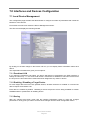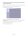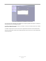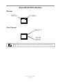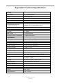
1
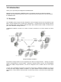
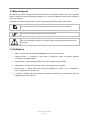
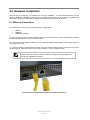
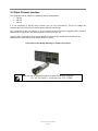
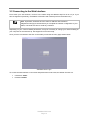
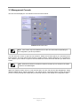
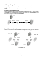
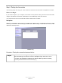
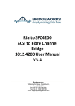
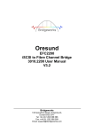
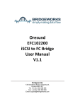
SANSlide SSFC100 Fibre Channel Node User Manual V1.2 Bridgeworks 135 Somerford Road, Christchurch, Dorset BH23 3PY Tel: +44 (0) 1202 588 588 Fax: +44 (0) 1202 588 589 Email: [email protected] Manual Revision History Revision 1.0 1.1 1.2 Date Firmware May 2012 V3_02 August 2012 V3_02 October 2013 V3_04 SANSlide SSFC100 Page 2 AP AP AP Warning The Bridgeworks SANSlide Node contains no user serviceable components. Only an authorised service centre should carry out servicing or repairs. Unauthorised repairs or modifications will immediately void your warranty. Before you start There are a number of additional pieces of equipment you will require for the successful installation of your Node: Ethernet Cable You will require a good quality cable of suitable length to go between your network access point and the Node. This should be marked as certified to Cat 5e and have a RJ45 style connector at the Node end. Fibre Channel Interface The Fibre Channel Node supports the use of SFP modules to connect top the Fibre Channel. You will require the correct type to connect to your existing infrastructure. Fibre Channel Cable In addition to the fibre channel interface, you will require a good quality cable of suitable length to go between your Bridge and your initiator, device or fibre channel switch. If you are in any doubt contact your reseller for extra assistance. Fibre Channel Node Page 3 Table of Contents 1.0 Introduction .................................................................................................................. 6 1.1 Overview ........................................................................................................................ 6 1.2 Manual Layout ............................................................................................................... 7 1.3 Definitions ...................................................................................................................... 7 2.0 Hardware Installation ......................................................................................................... 8 2.1 Ethernet Connection ...................................................................................................... 8 2.2 Fibre Channel Interface .................................................................................................. 9 2.3 Connecting the Power Supply ...................................................................................... 10 3.0 Using the Web Interface................................................................................................... 11 3.1 Browsers ...................................................................................................................... 11 3.2 Connecting to the Web Interface .................................................................................. 12 3.3 Management Console .................................................................................................. 13 4.0 Installation Set Up ............................................................................................................ 14 4.1 Example Configurations ........................................................................................... 15 Example 1: Remote tape libraries................................................................................... 15 Example 2: Across-site back up ..................................................................................... 15 4.2 Local Configuration ...................................................................................................... 16 Step 1: Configuring Network Connections ...................................................................... 17 Step 2: Testing the Connection ...................................................................................... 19 Step 3: Security Options (Optional) ................................................................................ 21 Step 4: Linking together the SANSlide Nodes ................................................................ 23 4.3 Installed Configuration.................................................................................................. 25 Step 5: Remotely Connecting to a Node (Optional) ........................................................ 26 Step 6: Configuring the FC Port Types ........................................................................... 28 Step 7: Configure the Initiator Ports (Optional) ............................................................... 29 Step 8: Configuring the Connected Hosts (Optional) ...................................................... 31 Step 9: Configuring the FC Target Ports......................................................................... 33 Step 10: Linking the Remote Devices to Local FC Interfaces (Optional) ......................... 35 Step 11: Refreshing the Devices .................................................................................... 37 Step 12: Instigating the Learn Process ........................................................................... 39 4.4 Installation Complete .................................................................................................... 41 5.0 Network Configuration...................................................................................................... 42 5.1 Connections ................................................................................................................. 42 5.2 Passwords and Security ............................................................................................... 44 5.3 Network Services ......................................................................................................... 45 5.3.1 NTP ....................................................................................................................... 45 5.3.2 Email Alerts ........................................................................................................... 45 6.0 SANSlide Configuration ................................................................................................... 47 6.1 Remote Node Management ......................................................................................... 47 6.1.1 Remote Control ..................................................................................................... 49 6.1.2 Configuring a Node ............................................................................................... 50 6.1.3 Learning ................................................................................................................ 50 6.1.4 Restoring of a Node .............................................................................................. 51 6.2 Remote Device Management ....................................................................................... 53 6.2.1 Enabling / Disabling a Target Device ..................................................................... 54 6.2.2 Restoring of Devices ............................................................................................. 54 6.3 Transfer Statistics ........................................................................................................ 55 7.0 Interfaces and Devices Configuration............................................................................... 57 7.1 Local Device Management ........................................................................................... 57 7.1.2 Enabling / Disabling a Target Device ..................................................................... 57 7.1.3 Saving ................................................................................................................... 57 7.2 Fibre Channel Initiator .................................................................................................. 58 7.2.1 Configuring the Fibre Channel Ports...................................................................... 59 7.2.2 Configuring Devices on the Remote Node ............................................................. 60 SANSlide SSFC100 Page 4 7.3 Fibre Channel Target ................................................................................................... 62 7.3.1 Configuring the Fibre Channel Ports...................................................................... 62 7.3.2 Linking the Remote Device to Local Fibre Channel Interfaces ............................... 63 8.0 Node Maintenance ........................................................................................................... 65 8.1 System Information ...................................................................................................... 65 8.2 System Log .................................................................................................................. 66 8.3 Firmware Updates ........................................................................................................ 67 8.4 Saving the Configuration to Disk .................................................................................. 68 8.5 Restore to Factory Defaults .......................................................................................... 69 9.0 Trouble Shooting.............................................................................................................. 70 9.1 Lost Password ............................................................................................................. 70 9.2 Lost IP Address ............................................................................................................ 71 Appendix A Setting up your computer for initial set up ........................................................... 72 A1 Windows 95, 98 or NT .................................................................................................. 72 A2 Windows 2000, 2003 or XP .......................................................................................... 73 A3 Windows Vista, Server 2008 or 7 .................................................................................. 75 Appendix B LED Indicators .................................................................................................... 77 Appendix C Technical Specifications ..................................................................................... 78 Fibre Channel Node Page 5 1.0 Introduction Thank you for purchasing the Bridgeworks SANSlide Node. Bridgeworks have designed the SANSlide product to be intuitive and easy to install and configure. However, we would recommend that you work in conjunction with this manual when you first configure the SANSlide Node. 1.1 Overview The SANSlide product range has been designed to connect storage devices over long distance, high latency TCP/IP networks with very little loss in performance. It supports all the major storage protocols such as Parallel SCSI, Fibre Channel, iSCSI and SAS. More interfaces will be added, as they become part of the mainstream storage protocols. A SANSlide installation consists of a number of Nodes connected via a TCP/IP network as shown below. Array VTL / Tape Library VTL / Tape Library SANSlide SANSlide Switch Array Switch SANSlide Switch Array VTL / Tape Library Example SANSlide Installation Each Node’s storage interface can be configured to act either as a target interface – working in a similar mode to a storage device, or as an initiator – working in a similar mode to a server. Or, if the SANSlide Node has multiple storage interfaces, one can be configured to be an initiator and one as a target device. A unique part of SANSlide functionality is that all the Nodes within a SANSlide installation do not have to have the same storage interface. Therefore, it is quite feasible to have the data centre Node connected to a Fibre Channel network whilst a remote Tape Library is connected via a parallel SCSI Node. SANSlide SSFC100 Page 6 1.2 Manual Layout This Manual has been divided into two primary sections an installation guide, and a more detailed section containing all of the functionality available to you, which is divided into sections that correspond to the web interface. Throughout the manual symbols will be used to quickly identify different pieces of information. This icon represents a note of interest about a step or section of information. This icon represents an important piece of information. This icon represents a warning, care must be taken and the warning should be read thoroughly. 1.3 Definitions Node – A Node refers to the physical SANSlide unit you have purchased. Initiating Device – A computer or other piece of equipment, which can perform backups connected to a SANSlide Node. Initiator Node – A Node which has both of its’ ports configured to be Initiators. Target Node – A Node which has both of its’ ports configured to be Targets. Remote Node – A Node, which has at least one initiating Port, which has, or is intended to have, a target device connected to it. Local Node - A Node, which has at least one Target Port, which has, or is intended to have, an initiating device connected to it. Fibre Channel Node Page 7 2.0 Hardware Installation The first step to configuring your Nodes is to set up the hardware. It is recommended that if you are going to follow the installation guide, that you first plug your hardware in at an easily accessible test area, before adding it to cabinets or shipping the remote board to your offsite location. 2.1 Ethernet Connection The Node can be used on the following network configurations: 10BaseT 100BaseT 1000BaseT (Gigabit) It is not necessary to specify which network type you are connected to, as when powered up the Node will automatically select the correct network speed. The connection to the Ethernet network is via an industry standard twisted pair, RJ45 copper interface on the front of the unit. To connect the Node to the Ethernet network, insert two Cat 5E cables into the connectors on the unit as shown below. When the plug is in the correct position a “click” should be heard. Note: SANSlide requires both Ethernet ports to be connected to the network. The left hand port is used to access the Node manager, the right hand port is used for the SANSlide connection. Front Panel of the Node Showing Ethernet Cable Connections SANSlide SSFC100 Page 8 2.2 Fibre Channel Interface The FC Bridge can be used on the following network configurations 1Gb FC 2Gb FC 4Gb FC It is not necessary to specify which network type you are connected to, as the FC Bridge will automatically select the correct network speed when first powered up. The connection to the FC network is via an industry Small Form-factor Pluggable (SFP) interface Module that is inserted into the SFP receptacle on the front of the unit. Once the SFP is inserted securely into the Bridge, insert one end of a fibre channel cable into the Bridge and the other end into your initiator, device or switch. Front Panel of the Bridge Showing FC Cable Connections Note: Only use an SFP that meets or exceeds the following standards: EU: IEC/EN 60825-1, North America: FCC, CDRH Fibre Channel Node Page 9 2.3 Connecting the Power Supply Before connecting the Power Supply to the unit, ensure the wall plug is removed or switched off. Connect the Power Supply to the rear of the Node as shown below. Note: Before powering up the Node, ensure all the peripherals are powered up and you have a connection to the network. To turn on the Node use the switch next to the power connector and push in the button. (The image above shows the button in the off position). Whenever the Node is powered on the blue LED on the front panel will be illuminated. Now that the Node is installed, the next stage is to configure it. This is described in the next chapter. SANSlide SSFC100 Page 10 3.0 Using the Web Interface Now the SANSlide Node is fully connected the primary method for configuring any option is through its web interface. The following section highlights the requirements needed to access these pages and the consistent layout used throughout. Note: The default IP address of the web interface for the Node is http://10.10.10.10/ 3.1 Browsers This Node supports the following browsers Microsoft Internet Explorer 7 Microsoft Internet Explorer 8 Microsoft Internet Explorer 9 Mozilla Firefox 10 Mozilla Firefox 11 Google Chrome Latest Note: JavaScript must be enabled within the web browser to use the web interfaces functionality. Important: If you choose to use a browser that is not on the list of supported browsers Bridgeworks cannot guarantee the behaviour of the Nodes functionality. Fibre Channel Node Page 11 3.2 Connecting to the Web Interface From within your web browser, connect to the Node using the address http://10.10.10.10/ (or if you have changed this previously, the address of the left-hand network port from the bottom two). Note: By default, all Nodes have the same IP address and Hostname. Bridgeworks strongly recommend that you complete the network configuration of your Nodes, one Node at a time to avoid any confusion. Depending on your current network parameters, it may be necessary to change your network setting on your computer for the initial set up. See Appendix A for further help. Once you have connected to the GUI on the Node you will see the entry page shown below. SANSlide Node Login To access the web interface a user name and password must be used, the default of which are: Username: admin Password: admin SANSlide SSFC100 Page 12 3.3 Management Console The GUI will now display the root selection screen as shown below. SANSlide Node main menu Note: Your screen may have different icons to the one shown above depending on the configuration you have purchased You will notice the screen is split into two sections. Within the left hand panel you will observe two further panels. The upper panel “Node Control” typically remains constant wherever you are within the GUI, it allows you to reboot or logout of the GUI whilst the console home link will take you back to this screen. Note: Whenever a Reboot command is issued it can take up to a minute for the Node to become accessible again. Within the Support section there is a link that will open up your mail service with Bridgeworks’ Email address loaded and an Online Help button. The Online help is contextually aware of which GUI page you are currently viewing and will provide you with help relevant to the display and configuration data. Fibre Channel Node Page 13 4.0 Installation Set Up To avoid travelling between sites where the Nodes are installed, Bridgeworks has included a feature within the GUI making it is possible to connect to and manage, a remote Node from another Node. However, to achieve this, the IP address of the remote Nodes WAN port must be known, therefore, the steps are divided into two sections: Local Configuration: these steps are preformed with you having direct access to both Nodes. Installed Configuration: these steps are preformed with one of the Nodes being configured in a remote location. If at any point during the installation guide a mistake is made, or you become worried about the configuration you have entered, the Node can be restored back to factory defaults and the process can be started again, see the section 8.5 Restore to Factory Defaults. SANSlide SSFC100 Page 14 4.1 Example Configurations The following examples will be used throughout the rest of the Installation guide. If an example Node is not specifically referred to then that step is to be applied to both sets of example boards. It is recommended you choose the example that matches your requirements and follow the instructions provided. Example 1: Remote tape libraries Here we have a Server based in the data centre and an FC enabled Tape Library in a remote location. The SANSlide Node A in the data centre is configured to be a Target Node, whilst the SANSlide Node B in the remote location is configured to be an Initiator Node. Array VTL / Tape Library Switch SANSlide Node B SANSlide Node A Remote Tape Libraries Example 2: Across-site back up Here we have servers in both data centres backing up to a tape library located in the other data centre. In this case one interface on each Node C and D is configured to be a target port whilst the other interface is configured as an Initiator port. Site A Site B Switch VTL / Tape Library B Array Array SANSlide Node D SANSlide Node C VTL / Tape Library A Across Site back-up Fibre Channel Node Page 15 Switch 4.2 Local Configuration This section will take you through the steps required to configure the SANSlide Nodes so they can communicate with each other before connecting them to the storage networks and the link network. The local configuration will take you through the following steps: Step 1: Configuring Network Connections Step 2: Testing the Connection Step 3: Security Options (Optional) Step 4: Linking together the SANSlide Nodes Once these steps have been repeated for all your Nodes, the Nodes can be moved to their permanent respective positions. SANSlide SSFC100 Page 16 Step 1: Configuring Network Connections The following steps will configure the networking options for your Nodes and should be completed for all Nodes. Basic Information The Node has two GbE (Gigabit Ethernet) Network ports located on the front of the unit. The left hand port is used to access the Node Management Console, the right hand port is used for the SANSlide link. There are two possibilities when configuring the IP addresses of the Node. The Management port can be configured in one of two ways: DHCP - The Node will seek out the DHCP server on your network and obtain an IP address from the server each time it powers up. With this option when accessing the web interface the host name will be entered into the web browser. Static IP - the IP address set in this page will be the IP address the unit will use each time it powers up. Network port two is the SANSlide connection and it must have a static IP address. It is recommended that a static address be used for the SANSlide links, Note: If you select the DHCP mode, Bridgeworks recommends you ensure your DHCP server is set to automatically update the DNS server. Before You Begin Depending on your current network parameters, it may be necessary to change your network setting on your computer for the initial set up. See Appendix A for further help. Note: By default, all Nodes have the same IP addresses and Hostnames. Ensure that these settings are unique to each Node. Navigation Click on the “Connections” button under the Network section of the main window. This will now bring up a new configuration page as shown below. Fibre Channel Node Page 17 Network Connections Procedure: Configuring network ports Steps: 1.1: Enter in the Hostname field the name you wish to use to address this Node in the future. It is recommended that you use a name that is relevant to its location and/or its’ purpose. 1.2: Enter in the IP address you have chosen or select DHCP for network port 1. Network port 2 is used for the SANSlide connection and must have a static IP address. 1.3: If the Node is configured to use DHCP the net mask will be issued from the DHCP server. If you are using a static IP address, enter the net mask in to this box. This must be done for any network port not using DHCP. 1.4: Click the save button to save these parameters and then click the reboot option under “Node Control” in the left hand pane. 1.5: To reconnect to the Node you will need to use the new Hostname or IP address for network port1, depending on which addressing mode you have selected. 1.6: Repeat step 1.1 to 1.5 for any additional Nodes and network ports you wish to configure. Note: None of these changes will take effect until a reboot is completed. Result When you next login to the web GUI you should now have to use your new network address. Related Topics 5.1 Connections 9.2 Lost IP Address SANSlide SSFC100 Page 18 Step 2: Testing the Connection The following steps will verify your chosen network connections and should be completed for all Nodes. Before You Begin If you made changes to your computer, return them to their previous setting and reconnect to the Node using the IP address or hostname, depending on which addressing mode you selected. You will need to have to hand at least two Cat5e or better network cables. Navigation Select the Connections page from the root page and at the top of the left-hand column in “Node Control” you will find a link to the ping window called “Network Ping”. Select this link. The GUI will display the following screen. Network Ping Procedure: Testing the connection between Nodes Steps: 2.1: Connect the Nodes together using network port two; the Node will automatically detect the cable type so either a crossover or straight through cable can be used. 2.2: Enter in the IP address of network port 2 from the Node you are not currently accessing the Web interface from and click ping. Fibre Channel Node Page 19 Result On a successful ping the text box below the buttons should fill with text similar to that below PING Address (Address): 56 data bytes 64 bytes from Address: seq=0 ttl=64 time=0.600 64 bytes from Address: seq=1 ttl=64 time=0.129 64 bytes from Address: seq=2 ttl=64 time=0.096 64 bytes from Address: seq=3 ttl=64 time=0.143 64 bytes from Address: seq=4 ttl=64 time=0.094 ms ms ms ms ms --- Address ping statistics --5 packets transmitted, 5 packets received, 0% packet loss round-trip min/avg/max = 0.094/0.212/0.600 ms Note: Where “Address” is the IP address you entered. If the results of the ping match the output above this completes the initial set up, if not please retry step 1. Related Topics 5.1 Connections SANSlide SSFC100 Page 20 Step 3: Security Options (Optional) You will only need to complete this step if: You want to change the password from the default. You want to enable HTTPS. This stage is not necessary for configuring the Nodes but for your security it is recommended to complete the following configuration changes. If you do not require these features or are going to configure them at a later stage proceed to step 4. The following can be completed for Example 1: Nodes A and B or Example 2: Nodes C and D. Navigation Click on the “Passwords & Security” button under the Network section of the main window. This will now bring up a new configuration page. Passwords and Security Procedure: Changing the Admin password and enabling HTTPS Steps: 3.1: Click the checkbox next to Enable HTTPS and click on save. A pop up message will inform you that you are going to be logged out, click “OK”. 3.2: Login to the Node again under HTTPS. 3.3: Navigate back to the “Passwords & Security” page. 3.4: Enter your existing password; the default is “admin” in the old password field. 3.5: Enter the new password of your choosing into the new password field. 3.6: Re-enter the new password of your choosing into the “Retype New Password” field. Fibre Channel Node Page 21 Result You are now using HTTPS within your browser; this can be verified by confirming the web address starts with https://. Depending on your browser or if you have completed these steps before, it may become necessary to accept a security certificate or specify to ignore an invalid certificate. Once the password has been changed successfully the message “Password successfully changed” will appear. Related Topics 5.2 Passwords and Security SANSlide SSFC100 Page 22 Step 4: Linking together the SANSlide Nodes The following steps will link together your Nodes and should be completed for all Nodes. Basic Information The IP address used to discover the Node is the address you have assigned to the WAN port on the Node you want to add. SANSlide will always attempt to get the best performance possible for the data it is transferring, however there may be other traffic on your network that will also need to accesses a share of your links bandwidth, this is where the configuring of a SANSlide Node comes in. Navigation From within the root window select the Remote Node Management icon. The following screen will be displayed. Remote Node Management Procedure: Adding a SANSlide Node Steps: 4.1: Click on the “Add Node” button 4.2: In the window that appears, enter the IP address then click the Add button. The unit will then search for the Node on the Link Network, as indicated by a blue progressing bar. 4.3: Click on “Ok” to confirm the Node. 4.4: If you have more than one Node, repeat this operation for all Remote Nodes. Note: These Nodes will be automatically saved, and will restore on reboot. Fibre Channel Node Page 23 Configuring a Node These steps are only necessary if you want to limit the amount of bandwidth SANSlide uses. Procedure: Limiting bandwidth Steps: 4.5: Select a Node from the Node list, when selected the background colour will become blue. 4.6: In the window that appears check the “Set Transfer Limit checkbox”. 4.7: Enter in the limiting value in Megabytes a second. 4.8: Click on “Ok” to start the limit. Note: The bandwidth limit will become instantly effective. Result The Remote Node(s) you have added will be displayed in the “List of Remote Nodes” list. Related Topics 6.1 Remote Node Management SANSlide SSFC100 Page 24 4.3 Installed Configuration Now you have completed the local configuration, the Nodes can now be relocated to their remote locations and the continuation of the configuration can be done remotely. The Installed Configuration will take you through the following steps: Step 5: Remotely Connecting to a Node (Optional) Step 6: Configuring the FC Port Types Step 7: Configure the Initiator Ports (Optional) Step 8: Configuring the Connected Hosts (Optional) Step 9: Configuring the FC Target Ports Step 10: Linking the Remote Devices to Local FC Interfaces (Optional) Step 11: Refreshing the Devices Step 12: Instigating the Learn Process Fibre Channel Node Page 25 Step 5: Remotely Connecting to a Node (Optional) You will only need to complete this step if: You want to configure the settings on a Node and do not have direct access to the web interface for that Node. During the set up of your Nodes it may not be possible to directly access the web interface on a Node, “remote control” can be used to take control of any other Node added to your local Node. Navigation From within the root window select the Remote Node Management icon. The following screen will be displayed. Remote Node Management Procedure: Starting remote Node control Steps: 5.1: Highlight the Node you wish to connect to by clicking the Node in the remote Node list. 5.2: Click the Start Remote Node Control button at the bottom of the list. 5.3: The Web Interface will now display the login screen of the remote Node as normal, login to that Node using the credentials of the remote Node. 5.4: Repeat this process with any other Nodes you may have to configure. SANSlide SSFC100 Page 26 Result Whenever a remote control session is underway there will be a yellow bar at the top of the web interface which will contain the name of the Node you are connected to, as illustrated below. A remote Node under remote control Related Topics 6.1 Remote Node Management Fibre Channel Node Page 27 Step 6: Configuring the FC Port Types The following steps will configure the type of the fibre channel port and should be completed for Example 1: Nodes A and B or Example 2: Nodes C and D. Navigation From the root menu select the FC Port Configuration icon. The GUI will display the following screen The screen for the Fibre Channel Port Configuration Procedure: Configuring the Fibre Channel Port Types Depending on the example configuration you are using please chose one and only one of the sets of steps below. Example 1: Remote tape libraries Steps: 6.1: For Node B Set both the FC Ports via the pull down menus to initiators and then click the save button. 6.2: From the Node Control menu click the “Reboot System” link. 6.3: For Node A Set both the FC Ports via the pull down menus to targets and then click the save button. 6.4: From the Node Control menu click the “Reboot System” link. Example 2: Across-site back up Steps: 6.1: For Node C set port 1 to be an initiator and port 2 to be a target and then click the save button. 6.2: From the Node Control menu click the “Reboot System” link. 6.3: For Node D set port 1 to be an initiator and port 2 to be a target and then click the save button. 6.4: From the Node Control menu click the “Reboot System” link. SANSlide SSFC100 Page 28 Step 7: Configure the Initiator Ports (Optional) You will only need to complete this step if: You want to manually set the link speed You want to change the ports topology The following Nodes Example 1: Node A, and Example 2: Node C, Node D are the only Nodes that may require the following steps, if you do not need to change these settings progress to the next step. Information The link speed pull down menu has 4 options Auto, 4Gb/s, 2Gb/s and 1Gb/s. It is recommended that you leave the option set to Auto. However some SFPs do not report their speed correctly, if you are unsure set the link speed to the SFP speed. The topology pull down menu has 3 options Auto, Loop (arbitrated Loop, FC-AL), and Point-to-Point (FC-P2P). Again the recommendation is you leave this as Auto unless you wish to force this into a know topology. Navigation Select the FC Initiator icon from the root menu. GUI will display the following screen. Fibre Channel Imitator Screen From within the screen select the port you wish to configure by clicking on the icon of a spanner under the port number. The screen will now display the following: Fibre Channel Node Page 29 Fibre Channel Initiator Port Configuration screen Procedure: Configuring the Fibre Channel Initiator Ports Steps: 7.1: Select the link speed you require from the drop down menu. 7.2: Select the topology you require from the drop down menu. 7.3: Click on the save button to effect these changes 7.4: Repeat for the other FC initiator port for Example 1: Node A. Or the other Node you are currently not working on for Example 2. If you have already completed both sets proceed to the next step. 7.5: Reboot the Node, by selecting Reboot System under the left hand menu Node Control. Note: These changes will not come into effect until a reboot is initiated. Result Once the reboot has completed the green LED on the front panel of the board will flash to match the speed you have set the port to. Related Topics 7.2 Fibre Channel Initiator Appendix B LED Indicators SANSlide SSFC100 Page 30 Step 8: Configuring the Connected Hosts (Optional) You will only need to complete this step if: You want to limit the target devices presented to the Node If all the devices connected to the Remote Node’s FC interface are to be enabled on the Local Node then nothing more is required so proceed to the next step. The following Nodes Example 1: Node A, and Example 2: Node C, Node D are the only Nodes that may require the following steps. Information All target devices are displayed by their WWN and are enabled by default until “Manual” is selected at which point all devices are disabled by default. Navigation From the Nodes root menu, select the FC initiator icon and then the Connected Targets icon from the second menu. The GUI will then display either of the following screens: Fibre Channel Initiator Enabled Remote Ports Screen in Automatic Mode Fibre Channel Node Page 31 Fibre Channel Initiator Enabled Remote Ports in Manual Mode Procedure: Configuring the Connected Hosts Steps: 8.1: If not already done so from the pull down menu, select manual and click save, the GUI will display the screen shown above. 8.2: To enable a target device select the device by clicking on its entry in the table. 8.3: Click the “Enable Button” at the bottom of the table. 8.4: Repeat Step 9.2 to 9.3 for any additional devices you want to enable. 8.5: Save the configuration by clicking the save button once you have made any changes. Related Topics 7.2 Fibre Channel Initiator Appendix B LED Indicators SANSlide SSFC100 Page 32 Step 9: Configuring the FC Target Ports You will only need to complete this step if: You want to manually set the link speed You want to change the ports topology If you don’t require changing these settings skip to the next step. The following Nodes Example 1: Node B, and Example 2: Node C, Node D are the only Nodes that may require the following steps. Information The link speed pull down menu has 4 options Auto, 4Gb/s, 2Gb/s and 1Gb/s. It is recommended that you leave the option set to Auto. However some SFP's do not report their speed correctly so if you are unsure set the link speed to the SFP speed. The topology pull down menu has 3 options Auto, Loop (arbitrated Loop, FC-AL), and Point-to-Point (FC-P2P). Again the recommendation is you leave this as Auto unless you wish to force this into a know topology. Navigation From the root menu select the FC target icon, the GUI will display the following screen. Fibre Channel Target Screen From within the screen select the port you wish to configure by clicking on the icon of a spanner under the port number. Fibre Channel Node Page 33 Fibre Channel Target Port Configuration Screen Procedure: Configuring the Fibre Channel Target Ports Steps: 9.1: Select the link speed you require, leave it as auto if you are unsure. 9.2: Select the topology you require, leave it as auto if you are unsure. 9.3: Click on the save button in order for these changes to take effect. 9.4: Repeat for the other FC Target Port for Example 1: Node B, or the other Node you are currently not working on for Example 2. If you have already completed both sets proceed to step 10.5. 9.5: Reboot the Node, by clicking Reboot System under Node Control in the left hand menu. Note: These changes will not come into effect until a reboot is initiated. Result Once the reboot has completed the green LED on the front panel of the board will flash to match the speed you have set the port to. Related Topics 7.3 Fibre Channel Target Appendix B LED Indicators SANSlide SSFC100 Page 34 Step 10: Linking the Remote Devices to Local FC Interfaces (Optional) You will only need to complete this step if: You only want to present certain target devices to specific target ports. The following Nodes Example 1: Node B, and Example 2: Node C, Node D are the only Nodes that may require the following steps. If you don’t require changing these settings skip to the next step. Information In Automatic mode the Local FC Node will map all the remote devices to both FC interfaces. For example, if the Remote Node has 4 FC devices enabled for presentation to the Local Node and the “Portmap’s” “Configuration Type” is set to Automatic, all 4 devices will be present on both FC target interfaces as LUNs 0-3. Navigation From the FC Target menu select the portmap icon (under global settings), the GUI will display either of the following screens. Fibre Channel Target Portmap screen in Automatic Mode Fibre Channel Node Page 35 Fibre Channel Target Portmap screen in Manual Mode with a Mapping assigned Procedure: Linking Remote Devices to Local Fibre Channel Interfaces Steps: Step 10.1: Change drop down menu from “Automatic” to “Manual” Step 10.2: Click on the save button, the Web interface will display extra controls. Note: At this point all devices are disabled until the assignments are added. Steps: 10.3: Select the device you want to be assigned from the Device & Logical Unit drop down list. 10.4: Select which FC port to present the target device on from the “Port” drop down menu. 10.5: Select the LUN of the device on the FC Interface; if this is the first assignment for your chosen port then the LUN must start on 0. 10.6: Click the “Add Assignment” button. 10.7: Repeat the steps 10.3 to 10.6 for each assignment you wish to make. Note: Devices can be allocated to each port but cannot be allocated again to the same port. Related Topics 7.3 Fibre Channel Target SANSlide SSFC100 Page 36 Step 11: Refreshing the Devices Once you have configured the devices and ports it may be necessary to refresh the devices on each of your Nodes to reflect any changes made in the previous steps. This step may not be necessary but is advised to make sure your Nodes are up to date. The following steps should be implemented for Target Nodes only. Navigation From the main menu select the “Remote Device Management” icon; the GUI will display the following screen. The Remote Device Management Page Procedure: Refreshing the device list Steps: 11.1: Select the Node you want to refresh the devices on from the “Host Name” list. When selected the Node will become blue. 11.2: Click on the “Refresh Devices” button at the bottom of the screen. The screen will go grey and a frame will appear with a blue loading bar. 11.3: Click on Ok to acknowledge the refreshed devices. 11.4: Repeat step 11.1 to 11.3 for each Node. Fibre Channel Node Page 37 Result Once completed a report will be returned informing you of the progress of the update. Every target device connected to the remote board that you have chosen to enable will be presented in the bottom list as shown below. The Remote Device Management Page with target devices attached to a remote Node Related Topics 6.2 Remote Device Management SANSlide SSFC100 Page 38 Step 12: Instigating the Learn Process This procedure will “kick start” the Artificial Intelligence module to start learning the characteristics of the link network. Once it has completed it will store these values in memory ready for use when data transfer starts. The Target Nodes are the only Nodes that may require the following steps. Navigation From the root menu select the remote Node Management icon; the GUI will display the following screen. Remote Node Management Procedure: Initiate a learn Steps: 12.1: Select the remote Node that you are going to use for the learn process from the List of Remote Nodes. 12.2: Click on the learn button just above the table. Note: The learn process can take up to 5 minutes to complete. Steps: 12.3: Once this has completed, as indicated by the bottom text displaying “Learn Complete”, the pop-up window can be closed. 12.4: Repeat step 12 for each of the Nodes you have added. Fibre Channel Node Page 39 Result A pop up window will display the learn transfer graph and once complete will display the words learn complete at the bottom of the screen. A Node in the process of a learn Related Topics 6.1 Remote Node Management SANSlide SSFC100 Page 40 4.4 Installation Complete Congratulations. You have now completed the installation guide. The next section covers each of the web interfaces functionality in more detail, if this still does not provide you with enough information please contact your reseller. Fibre Channel Node Page 41 5.0 Network Configuration This section will detail the operations of the following Network Configurations: 5.1 Connections 5.2 Passwords and Security 5.3 Network Services 5.1 Connections This configuration page will allow the administrator to configure network interface settings and to view network statistics. From within the main menu select the Network Control icon under the Network section The GUI will now display the following window Network Connections The SANSlide Node has two GbE network ports. One is used for the management port and one is used for the link between the SANSlide Nodes. The left hand physical port is designated as port 1 in the above window and the right hand port as port 2 Setting the Hostname In this box enter the name you wish to use to address this Node in the future. We suggest that you use a name that is relevant to its location and/or its purpose. Note: If you select the DHCP mode, ensure your DHCP server is set to automatically update the DNS server. Setting the MTU Enabling larger frames on a jumbo frame capable network can improve the performance of your backup operations. Jumbo frames are Ethernet frames that contain more than 1500 bytes of payload (MTU). Before enabling jumbo frames, ensure that all the devices/hosts located on the network support the jumbo frame size that you intend to use to connect to the Node. If you experience network related SANSlide SSFC100 Page 42 problems while using jumbo frames, use a smaller jumbo frame size. Consult your networking equipment documentation for additional instructions. Some networking switches require you to specify the size of the jumbo frame (MTU) when enabling, as opposed to a simple enable command. On these switches it might be required to add the necessary bytes needed for the frame header (i.e., header information + MTU). Typical header size is 28 bytes, so a 9000 byte MTU would translate to 9028 byte setting. Refer to your switch documentation to understand what the maximum frame size settings are for your switch. Setting the IP Address There are two possibilities when configuring the IP address of the Node: DHCP - this means the Node will seek out the DHCP sever on your network and obtain an IP address from the server each time it powers up. Static IP - the IP address set in this page will be the IP address the unit will use each time it powers up. Depending on the configuration, either click the DHCP button or set the Static IP address. Note: If you select the DHCP mode, ensure your DHCP server is set to automatically update the DNS server. Setting the Subnet Mask If the Node is configured to use DHCP the net mask will be issued from the DHCP server. If you are using static IP address enter the IP mask in this box. Committing the Changes Click the save button to save these parameters and then click the reboot option in the left hand pane. Fibre Channel Node Page 43 5.2 Passwords and Security This configuration page will allow the administrator to change the access password for the GUI. From within the main menu select the Password and Security icon under the Network section. The GUI will now display the following window Passwords and Security To change your password, type the existing password and the new password into the appropriate boxes and press save. Secure Connection – by clicking this box it will force all further transactions with the GUI to be done via a secure, encrypted HTTPS connection. Once you have clicked this option, save the configuration and log out then log in again. If you have lost your password please follow the steps in the Lost Password section of the Trouble Shooting chapter. SANSlide SSFC100 Page 44 5.3 Network Services Service Control Configuration page 5.3.1 NTP The Network Time Protocol (NTP) is a protocol for synchronising the clocks of computer systems over the IP network. This feature is particularly useful when viewing the logs to determine the time an event occurs. To enable NTP on the Node, click the tick box and enter the IP address for the NTP Server and then click the save button. 5.3.2 Email Alerts The SANSlide Node can notify a systems administrator when certain level log events are observed in the Nodes logs. To enable email alerts on the Node, click the tick box next to “Enable Alerts”, this will allow you to alter the contents of the currently greyed out fields. The following fields need to be completed. Recipient Email Address – This is the email address to which the emails will be sent. Senders Email Address - This is the email address that emails will be sent from. This can be any address and does not have to be genuine; which is useful for email filtering. For example entering in [email protected] would allow emails from this address to be filtered to a specified folder in the users email client. Trigger Event Log Level – This allows the user to specify what severity of event will trigger the log to be emailed with Critical Events being the most severe and Warning Events being the least. For each level picked the higher level logs will also be emailed, for example selecting Error Events will also send all Critical Events. Below are examples of events that will be sent for each log level Critical: Error: Warning: The Node is running at non recommended temperatures The Node was Unable to connect to another Node A Remote Controlled GUI Session has been stopped Fibre Channel Node Page 45 Note: For the following details consult your Network Administrator. SMTP server – The IP address of the Mail Server that will handle the transport of the event emails. SMTP Username – The username required to allow the use of the SMTP Server. SMTP Password – The password required to allow the use of the SMTP Server. SANSlide SSFC100 Page 46 6.0 SANSlide Configuration This section will detail the operations of the following SANSlide Configurations: 6.1 Remote Node Management 6.2 Remote Device Management 6.3 transfer Statistics 6.1 Remote Node Management This configuration page will allow the adding and removing of Nodes, the instigation of a learning cycle and the ability to take remote control of other Nodes. From within the main menu select the Remote Node Management icon under the Network section. The GUI will now display the following window Remote Node Management To add a Node, click on the “Add Node” button and then add the IP address of the Node to be connected to in the window as shown below, finally click the Add button. Fibre Channel Node Page 47 Remote Node Management: adding a Node The unit will then search for the Node on the Link Network, which will be displayed with a progress bar. Once completed a window will appear with the Nodes name and the number of target devices attached to that Node. Any remote Node that has been added to the local Node in this way will be automatically saved, and will restore on reboot until the Node is removed. The remote Node should then be displayed on the remote Node list as shown below. Remote Node Management: with a Node added To remove a Node that has been added simply select the Node from the list you want to remove and click the Remove Node button. A confirmation box will appear, click OK to continue. SANSlide SSFC100 Page 48 6.1.1 Remote Control During the set up of your Nodes it may not be possible to directly access the web interface on a Node you want, “remote control” can be used to take control of any other Node added to your local Node. To stop or allow other Nodes to take remote control of the Node you are currently using there is a checkbox within the home Node section at the top of the page. Select the checkbox if you want to allow other users to take control, deselect it if not. Once you have chosen click the save button. Highlight the Node you wish to connect to by clicking the Node in the remote Node list and then the Start Remote Node Control button at the bottom of the list. The web interface will now display the login screen of the remote Node as normal, and you login in the normal way using the credentials of the remote Node. Whenever a remote control session is underway there will be a yellow bar at the top of the web interface which will contain the name of the Node you are connected to, as illustrated below. A remote Node under Remote Control If you close down the window or tab containing the remote control session you can navigate back at any point to the Remote Node Management page on your Local Node, select the Node you had previous remote control over and click the “Reload Remote Window” button. When you have finished configuring the remote Node, clicking “Stop Remote Control” from the Remote Node Management page will end the remote control session. Fibre Channel Node Page 49 6.1.2 Configuring a Node When a Node has been restarted and it is in the process of re-establishing its link to another Node, the words Connecting may appear next to the Nodes name in brackets and the text will be in italics as shown below. A Node in the process of restoring its Links During this time it is not possible to use the features of a Node apart from remove until the connection has been established. A repeat attempt at connecting to a Node can take up to a minute and if the Node fails it will continually retry. Any newly discovered Target Devices would be added automatically. 6.1.3 Learning This procedure will “kick start” the Artificial Intelligence module to start learning the characteristics of the link network. Once it has completed it will store these values in the memory flash ready for use when data transfers start. From the root menu select the remote Node management icon; the GUI will display the following screen. Remote Node Management SANSlide SSFC100 Page 50 Select the remote Node that you are going to use for the learn process from the List of Remote Nodes window and then click on the learn button just above the window. You can start Multiple Nodes learning in this way simultaneously by clicking on each one and clicking learn. Note: The learn process can take up to 5 minutes to complete. The GUI will, in another window display the learn transfer graph as shown below. A Node in the process of a learn Each Node in the process of a learn can be viewed by clicking on the drop down list of Nodes and selecting the one you wish to monitor. Once this has completed, as indicated by the bottom text displaying “Learn Complete”, the Pop-up window can be closed. 6.1.4 Restoring of a Node When a Node has been restarted and it is in the process of re-establishing its link to another Node, the words Connecting may appear next to the Nodes name in brackets and the text will be in italics as shown below. Fibre Channel Node Page 51 A Node in the process of restoring its Links During this time it is not possible to use the features of a Node apart from remove until the connection has been established. A repeat attempt at connecting to a Node can take up to a minute and if the Node fails it will continually retry. Any newly discovered Target Devices would be added automatically. SANSlide SSFC100 Page 52 6.2 Remote Device Management This configuration page will allow the Adding and Removing of Nodes, the instigation of a learning cycle and the ability to take remote control of other Nodes. From within the main menu select the Remote Node Management icon under the Network section. The GUI will now display the following window Remote Device Management To refresh the devices on this list, select the Node you want to refresh the devices on from the “Host Name” list and click on it. When successfully selected the Node will become blue. Click on the “Refresh Devices” button at the bottom of the screen. The screen will go grey and a frame will appear with a blue loading bar as shown below. The Remote Device Management page in the process of an update Fibre Channel Node Page 53 When the loading bar is complete a report will be returned informing you of the progress of the update. The Remote Device Management Page, which has a Node with multiple Target Device 6.2.1 Enabling / Disabling a Target Device Disabling a target device will prevent it from being presented to your initiating device. All target devices are enabled by default. To disable a single device, uncheck the tick box next to the targets name. To enable a device, click the checkbox and make sure it has a visible tick within it. 6.2.2 Restoring of Devices When a Node has been restarted and it is in the process of re-establishing its link to another Node the word Connecting may appear next to the Nodes name, the target devices name in brackets and the text will be in italics as shown below. The Remote Device Management page in the process Linking Together Nodes All the functionality that can be used when a Node is active can be used whilst a Node is connecting but the effects will not occur until the link is up. SANSlide SSFC100 Page 54 6.3 Transfer Statistics This configuration page will allow you to monitor in real time the performance of a link over the span of a minute. From within the main menu select the Remote Node Management icon under the Network section. The GUI will now display the following window The Transfer Statistics Page without a Node being selected. This page will show you both the transmit and the receive rate for any selected Nodes, the transmit rate for a Node is in blue and the receive rate is in red. To view a Nodes transfer rate click on the name of the Node from the list and graphing will start automatically. Note: Because these parameters are always in a state of continual monitoring by the AI clicking to view these figures will not affect the performance of the data transfer. Fibre Channel Node Page 55 The Transfer Statistics Page with a Selected Node To find out the IP address of a Remote Node leave the mouse over it and it will be displayed in a pop up box. Offline A Node will be offline if the link between two SANSlide Nodes has not been re-established after a system restart. You cannot start the monitoring of the Node until the link has been re-established. The Transfer Statistics Page with the Node Offline SANSlide SSFC100 Page 56 7.0 Interfaces and Devices Configuration 7.1 Local Device Management This configuration page will allow the administrator to configure a number of parameters that control the behaviour of the devices. From within the main menu select the Device Management section. The GUI will now display the following window By clicking on the blue triangle in the Device info box you can display further information about each device. The expanded information also gives you two options. 7.1.1 Persistent LUN If you select the Persistent LUN option, the device will always be presented to the SCSI interface in exactly the same way – i.e. the same LUN number. If the device is disabled or has been removed from the FC port its LUN number will be reserved and not assigned to any other FC device. 7.1.2 Enabling / Disabling a Target Device For each target device there are two possible actions, whether the device is enabled or not and if the device requires a Persistent LUN. Each device is enabled by default. Disabling a device will prevent it from being available to another SANSlide Node or presented to an initiating device. 7.1.3 Saving After any changes have been made click the Update Configuration button to make the changes permanent. If at any point you want to remove those changes click the Clear Configuration button. Fibre Channel Node Page 57 7.2 Fibre Channel Initiator This configuration page will allow the administrator to configure the Fibre Channel Interface of the Node. From within the main menu select the FC Target icon from the SCSI System section. The GUI will now display the following window The left hand most icons display the current state of each Fibre Channel Port. The green / red arrow display whether the port is up or down whilst the number displays the negotiated Fibre Channel speed. Clicking on the icon will take you into a further screen displaying more detailed information Now select the first of the ports configuration icon The Screen will now display the following SANSlide SSFC100 Page 58 The link speed pull down menu has 4 options Auto, 4Gb/s, 2Gb/s, and 1Gb/s. It is recommended that you leave the option set to Auto. However some SFP’s do not report their speed correctly so if you are unsure set the link speed to the SFP speed The topology pull down menu has 3 options Auto, Loop (arbitrated Loop, FC-AL), and Point-to-Point (FC-P2P). Again the recommendation is you leave this as Auto unless you wish to force this into a know topology. Finally save the settings using the save button and return to FC Target menu. To enable the newly configured FC interfaces on to the SAN Network reboot the system using the reboot link in the upper left hand frame of the GUI. 7.2.1 Configuring the Fibre Channel Ports From within the screen select the port number you wish to configure and click the Configuration icon. The screen will now display the following Fibre Channel Target Port Configuration Fibre Channel Node Page 59 The link speed pull down menu has 4 options Auto, 4Gb/s, 2Gb/s, and 1Gb/s. It is recommended that you leave the option set to Auto. However some SFP do not report their speed correctly so if you are unsure set the link speed to the SFP speed The topology pull down menu has 3 options Auto, Loop (arbitrated Loop, FC-AL), and Point-to-Point (FC-P2P). Again the recommendation is you leave this as Auto unless you wish to force this into a know topology. Finally save the settings using the save button and return to FC Target menu. To enable the newly configured FC interfaces on to the SAN Network reboot the system using the reboot link in the upper left hand frame of the GUI. 7.2.2 Configuring Devices on the Remote Node Without any alteration to this section all the devices connected to the remote Node’s SAN (FC) connection will be identified within the Node’s device list. However if you only want to allow a subsection of the devices present on the Remote Nodes FC interface on the Local Node you will need to define which ones to enable. From the Remote Nodes root menu, select the FC initiator icon and then the Connected Targets icon from the second menu. The GUI will then display the following screen. Fibre Channel Initiator device configuration in automatic mode From the pull down menu select manual and the GUI will display the following screen SANSlide SSFC100 Page 60 Fibre Channel Initiator device configuration in manual mode All Target devices are displayed by their WWN and are enabled by default until “Manual” is selected at which point all devices are disabled by default. To enable a target device select the device by clicking on its entry in the table and then the “Enable Button” at the bottom of the table. To disable a Target device select an entry from the Target Selection table and click the Disable button. Click on the save button to effect these changes otherwise they will revert to the current setting when you exit the window. Fibre Channel Node Page 61 7.3 Fibre Channel Target From the root menu select the FC target icon and then the configuration icon The GUI will display the following screen. Fibre Channel Target Homepage 7.3.1 Configuring the Fibre Channel Ports From within the screen select the port number you wish to configure and click the Configuration icon. The screen will now display the following Fibre Channel Target Port Configuration The link speed pull down menu has 4 options Auto, 4Gb/s, 2Gb/s, and 1Gb/s. It is recommended that you leave the option set to Auto. However some SFP do not report their speed correctly so if you are unsure set the link speed to the SFP speed The topology pull down menu has 3 options Auto, Loop (arbitrated Loop, FC-AL), and Point-to-Point (FC-P2P). Again the recommendation is you leave this as Auto unless you wish to force this into a SANSlide SSFC100 Page 62 known topology. Finally save the settings using the save button and return to FC Target menu. To enable the newly configured FC interfaces on to the SAN Network reboot the system using the reboot link in the upper left hand frame of the GUI. 7.3.2 Linking the Remote Device to Local Fibre Channel Interfaces From the FC Target menu select the portmap icon (under global settings) The GUI will display the following screen In Automatic mode the Local Node will map all the devices to both FC interfaces. For example, if the Node has 4 FC devices enabled for presentation and the “Portmap’s” “Configuration Type” is set to Automatic all 4 devices will be present on both FC target interfaces as LUNs 0-3. If Manual portmap configuration is selected the GUI will display the following screen. From this menu it is possible to allocate devices to one or both FC interfaces. Fibre Channel Node Page 63 To enable a device Select the device from the Select a Target pull down menu. Select which FC port to present the target device. Select the LUN of the device on the FC Interface. If this is the first assignment for your chosen port then the LUN must start on 0. The example below shows device configured to FC port 0 as LUN 0 To remove a Mapping Select the mapping from the table you want to remove and click the remove button. Connected Hosts This section lists the current connections i.e. logged on, from FC hosts. SANSlide SSFC100 Page 64 8.0 Node Maintenance The following section describes the various pages that are available to the administrator to monitor the performance and maintain the Node. The following operations will be detailed. 8.1 System Information 8.2 System Log 8.3 Firmware Updates 8.4 Saving the Configuration to Disk 8.5 Restore Factory Defaults 8.1 System Information This System information page will allow the administrator to view the Performance of the Node. From within the main menu select the System Information icon from the Node Maintenance section. The GUI will now display the following window Within the top window the following information is displayed Current Firmware & Boot Loader Revision Level Serial Number of the PCB within the Node Within the lower window are 3 bar graphs, which provide an approximation of the follow performance parameters Data Throughput - This indicates the current performance in MB/s. CPU - This indicates the percentage of the time the CPU is occupied undertaking the management and scheduling the transfer of data between the two interfaces Memory usage - This indicates the percentage of memory used by all processes Fibre Channel Node Page 65 8.2 System Log This system information page will allow the administrator to view the log status that the Node encounters whilst running. From within the main menu select the View Log-file icon from the Node Maintenance section. The GUI will now display the following window The System Log Page with the Log cleared Below the log display pane are two options: Clear system logs – this will delete the current and saved logs within the Node Download – this will download the log files to your local disk. You may be asked by our support team to email this log file to them to aid them in any problem resolution. SANSlide SSFC100 Page 66 8.3 Firmware Updates From time to time it may be necessary to upgrade the firmware within the Node. New versions contain resolutions to known issues as well as new features and improvements to the functionality of the Node. It is advisable to check on the latest release on a regular basis. Where possible firmware on two communicating SANSlide Nodes should be kept consistent. New versions of the firmware can be downloaded from the Bridgeworks web site at: www.4bridgeworks.com/support/software.shtml Warning: Ensure you have the correct firmware for your product – IF IN DOUBT ASK. The Firmware Updates page will allow the administrator to load new firmware into the Node. From within the main menu select the Firmware Updates icon from the Node Maintenance section. The GUI will now display the following window The Firmware Update Page Once you have downloaded the new firmware to a local disk drive: Click on the browse button to locate the file you have downloaded from the website Then click on the update button. Updating the firmware will take a few minutes after which it will be necessary to reboot the system to bring the new code into memory. Fibre Channel Node Page 67 8.4 Saving the Configuration to Disk Once you have finished configuring your Node we recommend that you save your configuration data to a local disk. By doing so you could save valuable time if the unit requires replacement or if a configuration is lost during upgrades. It is also possible to create a “Boiler Plate” configuration and load this into each new Node as it is initialised. This can ease the rollout of multiple Nodes within an enterprise. From within the main menu select the Load Save Configuration icon from the Node Maintenance section. The GUI will now display the following window The Load/Save Configuration Page To save the configuration data click on the “Click here to Download” link from within the Export Configuration window located in the centre of the page. Depending upon the browser you are using, select the option to “save file to disk”. The Node will now download an encoded file that contains all the configuration settings for the Node. To reload the configuration, click on the “Browse” button and locate the required configuration to upload into the Node. Once located click the upload button and the new configuration data will be uploaded. Once completed, use the various configuration pages to make any further adjustments required and then reboot the system. SANSlide SSFC100 Page 68 8.5 Restore to Factory Defaults By clicking on this button all the parameters will be set back to the factory defaults. This includes IP address, hostname and passwords. We recommend that if you return the Node for maintenance that you reset to defaults to protect passwords and other sensitive information. If you are accessing your Node remotely over a SANSlide link, do not use this option as you wont be able to re-establish connection with your Node, Fibre Channel Node Page 69 9.0 Trouble Shooting 9.1 Lost Password If you have lost the admin password it is possible to reset it with help from Bridgeworks. First ensure that there is nothing entered into the user field and then type PASSWORDRESET into the password field. The unit will respond with a challenge key. Copy this key into an email along with your name, company and contact details – you must include your company’s personnel email address for security purposes. Send this email to [email protected] and a key will be returned for you to enter into the key field. Press the reset button once you have entered the key – this will reset the admin user password back to admin. SANSlide SSFC100 Page 70 9.2 Lost IP Address Introduction The utility will find any device irrespective of its IP address; this can be helpful in determining the IP address of a Bridgeworks device with an unknown IP address and for checking the number of Bridgeworks devices on a network. Downloading LAN Scan The utility can be downloaded from: http://www.4bridgeworks.com/support/software.shtml How to use LAN Scan The utility is available under both Windows and Linux, and is a CLI based tool. The downloaded file is in .zip format and contains the files lanscan, lanscan.exe and lanscan.bat. For the GNU/Linux operating system the lanscan executable is needed. For the Windows operating system the lanscan.exe and lanscan.bat files are required Linux Execute lanscan within a console and the output is displayed on screen. Windows Double click on lanscan.bat. This will create a file named lanscan.txt. Open lanscan.txt within a text editor to view the discovered Bridgeworks devices. Typical output Fibre Channel Node Page 71 Appendix A Setting up your computer for initial set up A1 Windows 95, 98 or NT If your computer is running Windows 95, 98 or NT follow the instructions below. For users with Windows 2000, 2003 or XP, instructions are detailed in Appendix A2 and for Windows Server 2008, 7 or Vista, instructions are detailed in Appendix A3. From the Start menu, choose Settings then Control Panel. Then click the Network icon In the Network window’s Configuration tab, Select the TCP/IP entry Then the Properties Button Click on the IP Address tab Make a Note of your current set up then: Click on the Specify an IP address button Enter 10.10.10.11 into the IP Address field Enter 255.255.255.0 into the Subnet Mask field Finally click the OK button and reboot your computer. Note: Once you have completed the initial set up of the Node, return your computer to the original settings and reconnect to the Node. SANSlide SSFC100 Page 72 A2 Windows 2000, 2003 or XP If your computer is running Windows, 2000, 2003 or XP follow the instructions below .For users with Windows 95, 98 or NT instructions are detailed in Appendix A1 and for Windows Server 2008, 7 or Vista, instructions are detailed in Appendix A3. From the Desktop or Start menu, select My Computer In the My Computer window select Network and Dial-up Connections positioned in the bottom left hand corner From within the displayed Network and Dial-up Connections select the interface connection that will be used to connect to the Node – in this example we have selected the Gigabit Ethernet interface. A general status page will be displayed. From within this page select Properties Fibre Channel Node Page 73 Select the Internet Protocol (TCP/IP) entry and then Properties Make a Note of your current set up then: Click Use the following IP Address Enter 10.10.10.11 into the IP Address field Enter 255.255.255.0 into the Subnet Mask field Finally click the OK button. Note: Once you have completed the initial set up of the Node, return your computer to the original settings and reconnect to the Node. SANSlide SSFC100 Page 74 A3 Windows Vista, Server 2008 or 7 If your computer is running Windows, Vista or 7 follow the instructions below .For users with Windows 95, 98 or NT instructions are detailed in Appendix A1 and for Windows 2000, 2003 or XP, instructions are detailed in Appendix A2. From the Start menu, select Control Panel From the control panel select the Network and Internet link, followed by the Network and Sharing Centre link. Now you can see the Local Area connection dialogue box. Double click Local Area Connections. A general status page will be displayed. From within this page select Properties Select the Internet Protocol Version 4 (TCP/IP) entry and then Properties Fibre Channel Node Page 75 Make a Note of your current set up then: Click Use the following IP Address Enter 10.10.10.11 into the IP Address field Enter 255.255.255.0 into the Subnet Mask field Finally click the OK button. Note: Once you have completed the initial set up of the Node, return your computer to the original settings and reconnect to the Node. SANSlide SSFC100 Page 76 Appendix B LED Indicators Ethernet On = Link Off = No Link Flashing = Data On = 1000Mb/s Off = 10/100mb/s Fibre Channel Flashing = No Link Solid = Link FC Link Speed 1 Flash = 1Gb 2 Flash = 2Gb 3 Flash = 4Gb Note: During heavy data transfers, the LED’s may appear off for an extended period. Fibre Channel Node Page 77 Appendix C Technical Specifications Physical Form Factor 19” 1U Rack mount Depth 170mm (10.6 in) Height 44mm (1.7 in) Width 437mm (17.2 in) Weight 5.1Kg Recommended minimum clearance for cooling 100mm (4.in) on front and rear faces Electrical Input voltage 110 –240V Frequency 50 –60Hz Input current 1 Amp Maximum Maximum Power Consumption 60 Watts Maximum Environmental Operating 0 to 40C (32F to 104F) Non Operating -20C to 60C (-4F to 140F) Operating Humidity 5% to 90% Non-condensing Storage Humidity 5% to 90% Non-condensing Operating Altitude 3,000m (9,842ft) Non Operating Altitude 8,000m (26,250ft) Fibre Channel Interface Physical Interface 2 SFP GBIC connectors Speed Topology 4Gb, 2Gb, 1Gb Auto or manual selected FC-AL, FC-PLDA, FC-PH, FC-FLA, FCP-SCSI, FC-FS, FC-TAPE NL-Port, FL_Port, F_Port, N_Port Visual Indicators Link connection, Link Speed Protocol Ethernet Interface Physical RJ45 Speed 10, 100, 1000Mb/s Protocol IPv4, IPv6 Visual Indicators Link, Activity SANSlide SSFC100 Page 78