1
Cat. No. Z253-E1-02
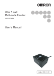
Bar Code Reader V500-R521B2/C2
Bar Code Reader
V500-R521B2/C2
User’s Manual
User’s Manual
OMRON Corporation
Industrial Automation Company
Sensing Devices Division H.Q.
Application Sensors Division
Shiokoji Horikawa, Shimogyo-ku,
Kyoto, 600-8530 Japan
Tel: (81) 75-344-7068/Fax: (81) 75-344-7107
Regional Headquarters
OMRON EUROPE B.V.
Sensor Business Unit
Carl-Benz-Str. 4, D-71154 Nufringen,
Germany
Tel: (49) 7032-811-0/Fax: (49) 7032-811-199
OMRON ELECTRONICS LLC
One Commerce Drive Schaumburg,
IL 60173-5302 U.S.A.
Tel: (1) 847-843-7900/Fax: (1) 847-843-7787
Authorized Distributor:
OMRON ASIA PACIFIC PTE. LTD.
No. 438A Alexandra Road # 05-05/08 (Lobby 2),
Alexandra Technopark, Singapore 119967
Tel: (65) 6835-3011/Fax: (65) 6835-2711
OMRON (CHINA) CO., LTD.
Room 2211, Bank of China Tower,
200 Yin Cheng Zhong Road,
PuDong New Area, Shanghai, 200120, China
Tel: (86) 21-5037-2222/Fax: (86) 21-5037-2200
OMRON Industrial Automation Global: www.ia.omron.com
© OMRON Corporation 2007 All Rights Reserved.
In the interest of product improvement,
specifications are subject to change without notice.
Printed in Japan
Cat. No. Z153-E1-02
0708-0.5C (0307) (M)
Cat. No.
Z253-E1-02
Introduction
Thank you for purchasing the OMRON V500-R521B2/C2.
This manual describes the functions, performance, and application
methods of the V500-R521B2/C2.
This manual is intended for personnel with knowledge of electrical
systems. Be sure to read and understand this manual thoroughly before
using the product, and keep this manual in an easily accessible location
for quick reference when required.
V500-R521.book
1 ページ
2008年7月18日 金曜日 午後1時1分
Introduction
Section 2 Wiring and Installation
Section 3 Function Explanation
Section 4 Setting Method
Section 5 Example of System Configuration
Bar Code Reader
User’s Manual
V500-R521B2
V500-R521C2
Appendix
Section 6 Appendix
Section 11 Section
Section 22 Section
Section 33 Section
Section 44 Section 5
Section
Section 1 Product Overview
Introduction
Introduc-
Introduction READ AND UNDERSTAND THIS DOCUMENT (Be sure to read this.)
V500-R521.book
2 ページ
2008年7月18日 金曜日 午後1時1分
Introduction
Introduction
READ AND UNDERSTAND THIS DOCUMENT
Please read and understand this document before using the products. Please consult your OMRON
representative if you have any questions or comments.
WARRANTY
OMRON’s exclusive warranty is that the products are free from defects in materials and workmanship for
a period of one year (or other period if specified) from date of sale by OMRON.
OMRON MAKES NO WARRANTY OR REPRESENTATION, EXPRESS OR IMPLIED, REGARDING
NON-INFRINGEMENT, MERCHANTABILITY, OR FITNESS FOR PARTICULAR PURPOSE OF THE
PRODUCTS. ANY BUYER OR USER ACKNOWLEDGES THAT THE BUYER OR USER ALONE HAS
DETERMINED THAT THE PRODUCTS WILL SUITABLY MEET THE REQUIREMENTS OF THEIR
INTENDED USE. OMRON DISCLAIMS ALL OTHER WARRANTIES, EXPRESS OR IMPLIED.
LIMITATIONS OF LIABILITY
OMRON SHALL NOT BE RESPONSIBLE FOR SPECIAL, INDIRECT, OR CONSEQUENTIAL
DAMAGES, LOSS OF PROFITS OR COMMERCIAL LOSS IN ANY WAY CONNECTED WITH THE
PRODUCTS, WHETHER SUCH CLAIM IS BASED ON CONTRACT, WARRANTY, NEGLIGENCE, OR
STRICT LIABILITY.
In no event shall responsibility of OMRON for any act exceed the individual price of the product on which
liability is asserted.
IN NO EVENT SHALL OMRON BE RESPONSIBLE FOR WARRANTY, REPAIR, OR OTHER CLAIMS
REGARDING THE PRODUCTS UNLESS OMRON’S ANALYSIS CONFIRMS THAT THE PRODUCTS
WERE PROPERLY HANDLED, STORED, INSTALLED, AND MAINTAINED AND NOT SUBJECT TO
CONTAMINATION, ABUSE, MISUSE, OR INAPPROPRIATE MODIFICATION OR REPAIR.
SUITABILITY FOR USE
THE PRODUCTS CONTAINED IN THIS DOCUMENT ARE NOT SAFETY RATED. THEY ARE NOT
DESIGNED OR RATED FOR ENSURING SAFETY OF PERSONS, AND SHOULD NOT BE RELIED
UPON AS A SAFETY COMPONENT OR PROTECTIVE DEVICE FOR SUCH PURPOSES. Please refer
to separate catalogs for OMRON's safety rated products.
OMRON shall not be responsible for conformity with any standards, codes, or regulations that apply to
the combination of products in the customer’s application or use of the product.
At the customer’s request, OMRON will provide applicable third party certification documents identifying
ratings and limitations of use that apply to the products. This information by itself is not sufficient for a
complete determination of the suitability of the products in combination with the end product, machine,
system, or other application or use.
The following are some examples of applications for which particular attention must be given. This is not
intended to be an exhaustive list of all possible uses of the products, nor is it intended to imply that the
uses listed may be suitable for the products:
• Outdoor use, uses involving potential chemical contamination or electrical interference, or conditions or
uses not described in this document.
2
V500-R521B2/C2
User’s Manual
V500-R521.book
3 ページ
2008年7月18日 金曜日 午後1時1分
Introduction
Introduction
• Nuclear energy control systems, combustion systems, railroad systems, aviation systems, medical
equipment, amusement machines, vehicles, safety equipment, and installations subject to separate
industry or government regulations.
• Systems, machines, and equipment that could present a risk to life or property.
Please know and observe all prohibitions of use applicable to the products.
NEVER USE THE PRODUCTS FOR AN APPLICATION INVOLVING SERIOUS RISK TO LIFE OR
PROPERTY WITHOUT ENSURING THAT THE SYSTEM AS A WHOLE HAS BEEN DESIGNED TO
ADDRESS THE RISKS, AND THAT THE OMRON PRODUCT IS PROPERLY RATED AND INSTALLED
FOR THE INTENDED USE WITHIN THE OVERALL EQUIPMENT OR SYSTEM.
PERFORMANCE DATA
Performance data given in this document is provided as a guide for the user in determining suitability and
does not constitute a warranty. It may represent the result of OMRON’s test conditions, and the users
must correlate it to actual application requirements. Actual performance is subject to the OMRON
Warranty and Limitations of Liability.
CHANGE IN SPECIFICATIONS
Product specifications and accessories may be changed at any time based on improvements and other
reasons.
It is our practice to change model numbers when published ratings or features are changed, or when
significant construction changes are made. However, some specifications of the product may be
changed without any notice. When in doubt, special model numbers may be assigned to fix or establish
key specifications for your application on your request. Please consult with your OMRON representative
at any time to confirm actual specifications of purchased products.
DIMENSIONS AND WEIGHTS
Dimensions and weights are nominal and are not to be used for manufacturing purposes, even when
tolerances are shown.
ERRORS AND OMISSIONS
The information in this document has been carefully checked and is believed to be accurate; however, no
responsibility is assumed for clerical, typographical, or proofreading errors, or omissions.
PROGRAMMABLE PRODUCTS
OMRON shall not be responsible for the user’s programming of a programmable product, or any
consequence thereof.
COPYRIGHT AND COPY PERMISSION
This document shall not be copied for sales or promotions without permission.
This document is protected by copyright and is intended solely for use in conjunction with the product.
Please notify us before copying or reproducing this document in any manner, for any other purpose. If
copying or transmitting this document to another, please copy or transmit it in its entirety.
V500-R521B2/C2
User’s Manual
3
V500-R521.book
4 ページ
2008年7月18日 金曜日 午後1時1分
Introduction
Introduction
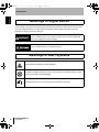
Meanings of Signal Words
In this manual, precautions are indicated using the following symbols and signal words to ensure safe
use of the V500-R521B2/C2. The precautions indicated by these symbols and signal words are
important for safety and must be observed.
WARNING
Indicates a potentially hazardous situation which, if not avoided, will result in
minor or moderate injury, or may result in serious injury or death. Additionally
there may be significant property damage.
Indicates a potentially hazardous situation which, if not avoided, may result in
minor or moderate injury or in property damage.
Meanings of Alert Symbols
Indicates the possibility of laser radiation.
Indicates prohibition when there is a risk of minor injury from electrical shock or other
source if the product is disassembled.
Indicates instruction for the user to always connect the ground wire.
4
V500-R521B2/C2
User’s Manual
V500-R521.book
5 ページ
2008年7月18日 金曜日 午後1時1分
Introduction
•
Introduction
For the Safety Use of Laser Products
Warning display
WARNING
Avoid eye exposure to direct or scattered radiation reflected by a mirror
surface.
Laser beam emitted from a laser has high power density and may become
blind when the beam is directed into eyes.
Do not disassemble this bar code reader.
Laser beam may be scattered around when it is disassembled.
This Bar Code Reader uses a laser as the light source.
Lasers are classified on IEC standard (IEC 60825-1).
V500-R521B2/R521C2
Wavelength
650 nm
Peak power
1 mW max.
Classification
2
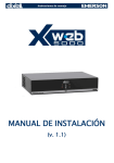
Labeling on Laser Use
The Bar Code Reader has the following WARNING Label on the bottom.
A different set of regulations, European, IEC 60825 applies when exporting this product to Europe.
Replace the warning label with the corresponding English label (supplied with this product.)
When using devices in which a Bar Code Reader is installed in the U.S., the product is subjected to the
U.S. FDA (Food and Drug Administration) laser regulations. Replace the warning label with the
corresponding English label (supplied with this product.)
Usage
• Use laser enclosure device to prevent specular object from reflecting laser beam.
When used without an enclosure, be sure to avoid a laser path from eye level.
• Although the safety distance (NOHD) is approximately 1 m; it is advisable, however, to terminate the laser on its path
if possible. Nonreflective, flatting material is recommendable for termination.
• Wear protective glassed to protect against laser light during set up and adjustment.
V500-R521B2/C2
User’s Manual
5
V500-R521.book
6 ページ
2008年7月18日 金曜日 午後1時1分
Introduction
Introduction
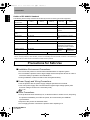
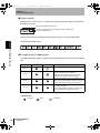
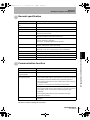
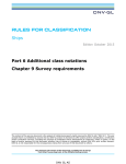
Outline of IEC 60825-1 Standard
The following are the safety measures to be taken by the user for each type of laser equipment.
Classification
Class 1
Required items
Class 2
Class 3A
Class 3B*
Class 4
Remote interlock
Not required
Connect to room or door circuits.
Key control
Not required
Remove key when not in use.
Beam attenuator
Not required
When in use prevents inadvertent
exposure.
Emission indicator
device
Not required
Indicates laser is energized.
Warning signs
Not required
Follow precautions on warning
signs.
Beam path
Not required
Specular reflection
Not required
Prevent unintentional reflections.
Eye protection
Not required
Required if engineering and
administrative procedures not
practicable and MPE exceeded.
Protective clothing
Not required
Sometimes
required.
Training
Not required
Terminate beam at end of useful length.
Specific
requirements.
Required for all operator and maintenance personnel.
∗ With respect to the requirements of remote interlock connector, key control, beam attenuator, emission indicator
device, and eye protection, Class 3B laser products not exceeding five times the AEL of Class 2 in the wavelength
range of 400 nm to 700 nm are to be treated as Class 3A laser products.
Precautions for Safe Use
Observe the following precautions to ensure safe use of the product.
■ Installation Environment Precautions
• Do not use the product in environments with flammable or explosive gases.
• Do not install the product close to high-voltage devices and power devices in order to
secure the safety of operation and maintenance.
• During installation, make sure that screws are tightened firmly.
■ Power Supply and Wiring Precautions
• Use the product with the power supply voltages specified in this manual.
• Use a DC power supply with countermeasures against high-voltage spikes (safe
extra low-voltage circuits on the secondary side).
p.30
■ Other Precautions
• If the product becomes extremely hot, or abnormal odors or smoke occurs, stop using
the product immediately, turn OFF the power, and consult with your OMRON
representative.
• Dispose of the product as industrial waste.
• Do not apply pressure or deform the product when disposing of it.
6
V500-R521B2/C2
User’s Manual
V500-R521.book
7 ページ
2008年7月18日 金曜日 午後1時1分
Introduction
Introduction
Precautions for Correct Use
Always observe the following precautions to prevent operation failures, malfunctions, and adverse effects
on performance and equipment.
1. Installation of the bar code reader
The bar code should be mounted in a place:
• where is not subject to direct sunlight (indoor use),
• without any corrosive gas, dust, metallic powder or salt content,
• where operation temperature does not exceed the specified range,
• where temperature change is not rapid, without dew condensation (within the
specified value),
• where humidity change is not rapid, without dew condensation (within the specified value),
• where vibration or shock does not reach to the bar code reader directly (within the
specified value),
• and without any droplet of water, oil or chemical agent.
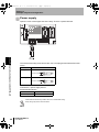
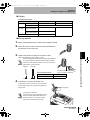
2. Power supply
• Apply voltage to be +5 VDC ±10 % at the connector of the bar code reader side.
• Used cable should be 0.3 mm2 or equivalent, within 5 m. When the wiring is too long
or resistance is too huge, voltage may be decreased due to fluctuation of
consumption current of the bar code reader.
• Be careful so that noise or switching surge of relay is not applied on +5 V power
voltage supplied to the bar code reader.
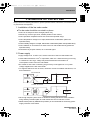
• To suppress influence such as noise, use direct current of insulation transformer, not
auto transformer.
Auto transformer
㧗
Commercial
power source
㧙
V500-R521
series
Insulation transformer
Commercial
power source
㧗
㧙
V500-R521
series
• When high frequency wave such as ultrasonic welding machine is used, insulate it
using auxiliary insulation plate to avoid malfunction due to induction current.
• S82K-00705 (made by OMRON Corporation) is recommended for the driving power
supply of the bar code reader.
V500-R521B2/C2
User’s Manual
7
V500-R521.book
8 ページ
2008年7月18日 金曜日 午後1時1分
Introduction
Introduction
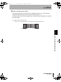
3. Wiring
• Extension length of the RS-232C line (SD, RD, SG) should be up to 15 m.
• For trigger and power line, use a cable with 0.3 mm2 or more and extension length
should be up to 5 m.
• Wiring should avoid approaching to a high-power heavy electric current wire.
• Check the polarity of terminals and be careful of faulty wiring.
• Avoid reverse connection of power supply or connection to alternating current.
• Turn off the power switch before connecting or disconnecting a connector.
• Use a wrist strap etc. to avoid electrostatic charge when you touch terminals and
signal lines, to avoid damage due to static electricity.
4. Installation
• When using the bar code reader, fix it to the associated mounting bracket.
• When inductive noise is generated at the mounting bracket, attach an associated
insulation board. Use the associated screw to mount the insulation board.
• Incline the bar code reader about 15 ° to read the target bar code.
• Do not apply stress on the cable when mounting and using.
• Distance and angle allowed to read differs according the bar code. Check if the used
bar code can be read actually, before mounting.
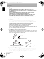
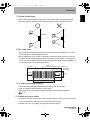
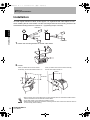
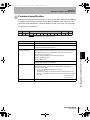
5. Timing input with photo-electronic sensor
When taking timing with the photo-electronic sensor, mount the bar code reader so that
the footlight beam of the photo-electronic sensor does not spot directly on the reading
window of the bar code reader or on the bar code.
Bar code
Photo-electronic sensor
Footlight beam of the photo-electronic sensor spots
on the reading window of the bar code reader.
Footlight beam of the photoelectronic sensor spots on the
bar code.
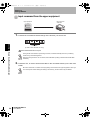
6. Influence of reflective objects
When there is any reflective object such as metal or mirror surface on the bar code
beam-scanning surface, reading character may be deteriorate. Cover the reflective
object with something or change the bar code position to avoid influence.
8
V500-R521B2/C2
User’s Manual
V500-R521.book
9 ページ
2008年7月18日 金曜日 午後1時1分
Introduction
When mounting the bar code readers side-by-side, laser beams may interfere reading
each other. The bar code readers should be placed far enough not to affect reading.
Introduction
7. Mutual interference
Bar code
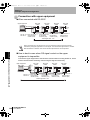
8. Bar code label
• The height of the bar code should be more than the luster scan width (max. 10 mm)
and use a label considering attaching error.
• When reading bar code, margin is necessary on the both sides of the bar code. Set
the label so that margin parts do not hide. A space of one character or more and 2.5
mm or more is necessary of both right and left side of the label. (Rough standard: 12
or 13 times or more of the narrow bar width)
Label
(Paper which a bar code is printed on)
Narrow bar
(Slim lines)
Bar code
Margin
Margin
Height
Width
9. To improve reading reliability
• When the digit is determined, designate the digit to use the bar code.
• Use the modulus check (addition of check digit).
• Bar codes other than the reading object should be set to reading prohibition.
p.61
10. Maintenance and check
• Check for any dust or dirt on the reading window regularly. When it is dirty, wipe with
a dry, soft and clean cloth. Do not use solutions such as thinner.
• Handle with care, not to apply strong shock such as dropping.
V500-R521B2/C2
User’s Manual
9
V500-R521.book
10 ページ
2008年7月18日 金曜日 午後1時1分
Introduction
Introduction
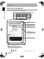
How to Use This Manual
In this manual, each part of the bar code is described as follows.
How to Use This Manual
Label
(Paper which a bar code is printed on)
Narrow bar
(Slim lines)
Bar code
Margin
Margin
Height
Width
For a page format
Section title
Section 4
System Settings
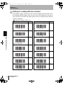
Creating Setting Files Using the 2DCR Configear
Section 4
System Settings
Outline
Creates the data setting file for loading set data to the Handheld 2D Code Reader.
Make the settings for the communications conditions, functions, and display conversion.
Move to the setting screen.
Select Setting Reader - Create Data... from the menu.
The following window for creating the setting data file will be displayed.
Screen display
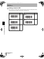
The [Receive (R)] function can be used to open the data file downloaded from the Code
■ Save
Saves the created data setting file.
To save data to the Memory Card, create a folder with the name SETTINGS, and save. If the data is
saved to a folder other than “SETTINGS”, it cannot be uploaded.
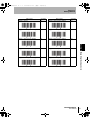
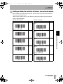
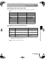
Communication Settings
The settings shown in the following table are set in the Communication Settings Tab
Page in the Create Setting Data Window.
Setting item
Parity
Data Length
Stop Bit
Prefix
Suffix
FCS
Index label
Provides the section number
and subject matter. Can be
used to immediately open the
desired page.
Describes the settings.
Settings
Baud Rate
Header/Footer
Section 4 Uploading from the Memory Card
Opens the previously created data setting file for editing.
Reader and edit it.
Section 4 Creating Setting Files Using the 2DCR Configear
■ Open
9,600*, 19,200, or 38,400
None*, odd, or even
*
77 bits or 8 bits
1sbit* or 2 bits
None*, 02 <STX>, or 1B <ESC>
*
ETX, 0A LF, 0D CR , or 0D0A CR+LF
ON or OFF*
The default settings are indicated with an asterisk.
V500-R521B2/C2
User’s Manual
65
V500-R521B2/C2
User’s Manual
69
Procedure and additional explanations
Information useful during the operation and reference
pages are provided here with special marks to indicate
the kind of information being provided.
*This page does not actually exist in this manual.
10
V500-R521B2/C2
User’s Manual
V500-R521.book
11 ページ
2008年7月18日 金曜日 午後1時1分
Introduction
Introduction
Visual Aids
Indicates points that are important in using product functions or in application procedures.
Visual Aids
Indicates page numbers providing related information.
Indicates helpful information when a problem occurs and explanations of technical terms.
V500-R521B2/C2
User’s Manual
11
V500-R521.book
12 ページ
2008年7月18日 金曜日 午後1時1分
Introduction
Introduction
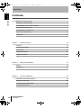
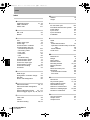
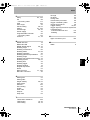
Contents
Introduction
Contents
Meanings of Signal Words
4
Meanings of Alert Symbols
4
For the Safety Use of Laser Products
5
Precautions for Safe Use
6
Precautions for Correct Use
7
How to Use This Manual
10
Visual Aids
11
Section 1
15
Features
16
Product Composition
18
Part Names
19
Rating/Performance
20
Usage Flow Chart
24
Section 2
Wiring and Installation
27
Wiring
28
Installation
32
Section 3
12
Product Overview
Function Explanation
35
Explanation of Reading System
36
Operation Flow Chart
38
Communication Data Format
46
Test Reading Function
49
V500-R521B2/C2
User’s Manual
V500-R521.book
13 ページ
2008年7月18日 金曜日 午後1時1分
Introduction
Setting Method
51
52
Menu Sheet/Command List
56
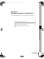
Section 5
Example of System Configuration
87
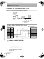
Example of Connection with a PC
88
Example of Connection with Programmable Controller (CS1)
89
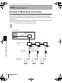
Example of Multi-drop Connection
92
How to Use Command Link Unit V700-L12
96
Section 6
Appendix
Contents
How to Use Menu Sheet/Command
Introduction
Section 4
113
External Dimension
114
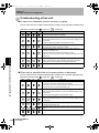
Troubleshooting
120
ASCII Code Table
121
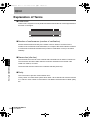
Explanation of Terms
122
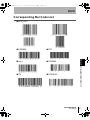
Corresponding Bar Code List
127
Revision History
132
V500-R521B2/C2
User’s Manual
13
V500-R521.book
14 ページ
2008年7月18日 金曜日 午後1時1分
Introduction
Introduction
MEMO
Contents
14
V500-R521B2/C2
User’s Manual
V500-R521.book
15 ページ
2008年7月18日 金曜日 午後1時1分
This section explains about features and rating/performance of this bar code
reader.
Features
16
Product Composition
18
Part Names
19
Rating/Performance
20
Usage Flow Chart
24
V500-R521B2/C2
User’s Manual
Section 1 Product Overview
Section 1
Product Overview
15
V500-R521.book
16 ページ
2008年7月18日 金曜日 午後1時1分
Section 1
Product Overview
Features
A bar code reader is a device to read a bar code attached on a product and transfer the
Section 1 Features
information to upper equipment.
Various types of information can be managed efficiently by using it combining with PC and
programmable controllers.
Problems on site
Bar code solution!
Work data are recorded on papers.
> Reading and writing mistakes and
distribution of workers exist.
> Formats are difficult to learn because various
kinds are produced in small numbers.
Register product numbers and setting on PC
and programmable controllers beforehand and
import a product number only by reading a bar
code. Input mistake or distribution of workers
are eliminated.
Cost should be as cheap as possible as
the product price is low.
Cost is very low by only attaching a printed bar
code label.
Ultra-compact design
Optimum for the assembly to each device
Easy installation
Easy to read by pressing the TEST button and know the reading rate with LED
illumination and buzzer sound in real time.
As reading position is easy to check at site before connecting with upper equipment,
installation work and maintenance work hour can be greatly reduced.
p.49
Simple function setting
You can either set the function by reading a menu sheet or by inputting a command on
the upper equipment. You can select the setting method according to the condition.
p.52
16
V500-R521B2/C2
User’s Manual
V500-R521.book
17 ページ
2008年7月18日 金曜日 午後1時1分
Section 1
Product Overview
Perfect reading performance
High speed reading with 500 scan/sec. realized high reliability and wide reading
distance of 60 mm to 270 mm (in case of narrow bar width 1.0 mm).
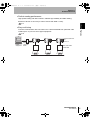
Easy multi-drop
Connect communication link unit V700-L12 to collect read data from plural bar code
readers (max. 31) for one set of upper equipment.
p.92
Section 1 Features
p.21
Communication link
unit
V700-L12
Upper
equipment
Communication
converter
K3SC
Bar code reader
V500-R521
Max. 31 sets
V500-R521B2/C2
User’s Manual
17
V500-R521.book
18 ページ
2008年7月18日 金曜日 午後1時1分
Section 1
Product Overview
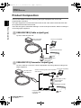
Product Composition
The bar code reader is used by connecting with upper equipment such as PC and
Section 1 Product Composition
programmable controllers.
The upper equipment receives information which the bar code reader reads and refers with
the registered information and records.
There are two types in V500-R521 differing in connector shape as follows. Select according to
connecting upper equipment.
V500-R521B2 (Cable output type)
Tip of the cable is loose end.
Bar code reader
V500-R521B2
PC (PC/AT compatible)
p.88
Programmable controller
p.89
Power supply (5 VDC)
Recommended:
S8VS-01505
V500-R521C2 (Connecter output type)
Tip of the cable is a connector. Use an appropriate connecting cable according to the
upper equipment.
PC (PC/AT compatible)
Bar code reader
V500-R521C2
Cable for connecting with PC/AT compatible
V509-W011D
p.88
Power supply (5 VDC)
Recommended:
S8VS-01505
Programmable controller
Programmable controller made by OMRON
Connecting cable
V509-W011
18
V500-R521B2/C2
User’s Manual
p.89
V500-R521.book
19 ページ
2008年7月18日 金曜日 午後1時1分
Section 1
Product Overview
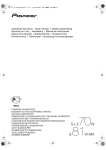
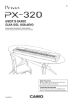
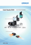
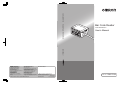
Part Names
Section 1 Part Names
Front side
Main cable (2 m)
Laser alarm label (bottom side)
Reading window
Laser beam radiates from here
Back side
READ OK LED
Illuminates when read correctly.
TEST button
Press it once to read once.
Test Reading Function p.49
READ NG LED
Illuminates when not read correctly.
V500-R521B2/C2
User’s Manual
19
V500-R521.book
20 ページ
2008年7月18日 金曜日 午後1時1分
Section 1
Product Overview
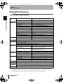
Rating/Performance
Section 1 Rating/Performance
General specification
Applicable bar
code
Types of bar code
Number of reading digits
32 digits MAX (Changes according to bar width and reading size)
Reading
performance (*1)
Resolution
0.15 mm (at PCS 0.9)
Contrast (PCS)
0.45 or more (white reflectance 70 % or more)
Interface
EAN/UPC (A, E), CODE39, NW-7, ITF
STF (2 of 5 bar), CODE93, CODE128 (including EAN128)
Reading distance
60 to 270 mm (At narrow bar: 1.0 mm)
Reading angle
Within 40 ° (Including margins at left and right sides)
Skew angle
±50 ° (However, exclude from 10 ° upper side to 5 ° lower side)
Pitch angle
±25 ° (Left and right 25 °)
Light source
Red semiconductor laser (Wave length: 650 nm)
Light output
1.0 mW or less (Correspond to JIS class 2)
Scan type
Luster scan
Number of scan
500 scan/sec.
Number of reading coincidence
2 to 6 times (Verification: 1 to 5 times)
Reading check
Buzzer sound, indication LED
Communication specification
RS-232C
OK/NG output (Only V500-R521B2)
NPN open collector output 24 VDC, 30 mA
Function set method Menu sheet reading method or host command method
Reading trigger
External trigger (Transistor input)
Trigger by command (RS-232C)
Trigger a test reading by pressing the TEST button on the product
Reading result
output
Power supply
specification
Environment
Enclosure rating
RS-232C output
Reading data output
OK/NG signal
(Only V500-R521B2)
OK signal is turned on when reading succeeded
NG signal is turned on when reading failed
Indication LED
OK LED illuminates when reading succeeded
NG LED illuminates when reading failed
Buzzer
Notifies a successful reading with a buzzer sound (Muting available)
Power voltage
5 VDC ±10 % (*2)
Consumption current
220 mA typ. (330 mA MAX)
Inrush current
2.5 A MAX
Ambient temperature
At operation: 0 to + 45 °C; At storage: -10 to + 60 °C
Ambient humidity
At operation and storage: 30 to 85 % RH (Without due condensation)
Vibration resistance
12 to 100 Hz 19.6 m/s2 (2G) X, Y, Z, 3H each
Ambient light resistance
3000 lx or less (Fluorescent lamp. Excluding inverter florescent lamp.)
IP54 (IEC60529 Standard)
Mass
80 g (Excluding cables and connectors)
Input/output
connector
V500-R521B2: Cable output
Code length
2m
V500-R521C2: DIN 8 pin connector
*1
Unless otherwise specified, use a bar code of EAN 1x, MRD 63 % or more (PCS = 0.9 or more).
*2
Power voltage is specified at the input/output connecter end of the bar code reader side.
Specified at a condition of pitch angle α = 0 °, skew angle β = 0 °, tilt angle γ = 0 °, curvature R = ∞
20
V500-R521B2/C2
User’s Manual
V500-R521.book
21 ページ
2008年7月18日 金曜日 午後1時1分
Section 1
Product Overview
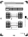
Number of reading range performance
Explained with examples of following conditions:
MRD 63 % (PCS = 0.9)
• Bar code:
CODE39
• Installation condition: Pitch angle α = 0 °, skew angle β = 15 °
Tilt angle γ = 0 °, curvature R = ∞
Reading distance
(Unit: mm)
Section 1 Rating/Performance
• Contrast:
Narrow bar width
Narrow bar width
Reading distance
(*1)
A
0.15 mm (*2)
90 to 110 mm (*2)
B
0.2 mm
80 to 150 mm
C
0.25 mm
60 to 170 mm
D
0.5 mm
60 to 230 mm
E
1.0 mm
60 to 270 mm
*1
Distance from the end of the case.
*2
Value at a reading angle 30 ° .
V500-R521B2/C2
User’s Manual
21
V500-R521.book
22 ページ
2008年7月18日 金曜日 午後1時1分
Section 1
Product Overview
Reading angle performance
Section 1 Rating/Performance
Pitch angle
In the following conditions, readable up to α = 25 ° on either side.
• Bar code:
Resolution = 0.25 mm, CODE39 (9 digits), MRD 63 % (PCS = 0.9)
• Reading distance:
100 mm from the case end
• Installation condition: Skew angle β = 15 °, tilt angle γ = 0 °, curvature R = ∞
Skew angle
In the following conditions, readable up to β = ± 50 °. However, range from β = -10 to +5 ° is
an area difficult to read due to regular reflection.
• Bar code:
Resolution = 0.25 mm, CODE39 (9 digits), MRD 63 % (PCS = 0.9)
• Reading distance:
100 mm from the case end
• Installation condition: Pitch angle α = 0 °, tilt angle γ = 0 °, curvature R = ∞
22
V500-R521B2/C2
User’s Manual
V500-R521.book
23 ページ
2008年7月18日 金曜日 午後1時1分
Section 1
Product Overview
Tilt angle
Generally, a tilt angle is not specified, because it differs according to the bar code
height.
Section 1 Rating/Performance
Scan all the bar code with the laser.
Curvature
In case of the following conditions, the bar code of 8-digit EAN, curvature range 15 mm
or more and 13-digit EAN, curvature range 20 mm or more can be read.
• Bar code:
Resolution = 0.26 mm, EAN, MRD 63 % (PCS = 0.9)
• Reading distance:
100 mm from the case end
• Installation condition: Pitch angle α = 0 °, skew angle β = 15 °, tilt angle γ = 0 °
V500-R521B2/C2
User’s Manual
23
V500-R521.book
24 ページ
2008年7月18日 金曜日 午後1時1分
Section 1
Product Overview
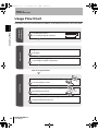
Usage Flow Chart
Examination of the bar code beforehand, installation, and introduction flow chart is as shown below.
Examination
beforehand
Section 1 Usage Flow Chart
Check the type, width, height and numbers of digit of bar codes.
p.20 Rating/Performance
p.127 Corresponding Bar Code List
Wiring.
Connection
p.28 Wiring
Connect peripheral equipment.
p.87 Example of System Configuration
Turn on the power switch.
Check that the bar code in subject can be read.
p.49 Test Reading Function
Preparation
Investigate the reading timing and moving speed.
p.38 Operation Flow Chart
Set the reading condition corresponding to the purpose.
p.56 Menu Sheet/Command List
24
V500-R521B2/C2
User’s Manual
V500-R521.book
25 ページ
2008年7月18日 金曜日 午後1時1分
Section 1
Product Overview
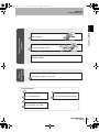
Section 1 Usage Flow Chart
Install.
p.32 Installation
Installation -
Execution of reading
Test in the actual usage environment.
p.49 Test Reading Function
Execute reading.
Applied way
of using
Read only the registered bar code.
p.83 Setting related to sorting read
In case of trouble:
A bar code cannot be read correctly.
I don't know the communication specification.
p.120 Troubleshooting
p.46 Communication Data Format
I can't understand the operation flow.
p.38 Operation Flow Chart
V500-R521B2/C2
User’s Manual
25
V500-R521.book
26 ページ
2008年7月18日 金曜日 午後1時1分
Section 1
Product Overview
MEMO
Section 1 Usage Flow Chart
26
V500-R521B2/C2
User’s Manual
V500-R521.book
27 ページ
2008年7月18日 金曜日 午後1時1分
Section 2
Wiring and Installation
bar code reader.
Wiring
28
Installation
32
V500-R521B2/C2
User’s Manual
Section 2 Wiring and Installation
This section explains about the wiring method and installation method of the
27
V500-R521.book
28 ページ
2008年7月18日 金曜日 午後1時1分
Section 2
Wiring and Installation
Wiring
Section 2 Wiring
•
•
•
•
•
•
•
•
Extension length of the RS-232C line (SD, RD, and SG) should be up to 15 m.
For trigger and power line, use a cable with 0.3 mm 2 or more and extension length should be up to 5 m.
Wiring should avoid approaching to a high-power heavy electric current wire.
Check the polarity of terminals and be careful of faulty wiring.
Avoid reverse connection of power supply or connection to alternating current.
Do not use exceeding rating voltage.
Turn off the power switch before connecting or disconnecting a connector.
Use a wrist strap etc. to avoid electrostatic charge when you touch terminals and signal lines, to avoid
damage due to static electricity.
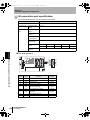
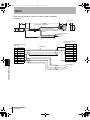
Wiring diagram
V500-R521B2 (Cable output type)
Wiring color
Signal
name
Function
Brown
TRIG
External trigger signal
Yellow
OK
READ OK signal
Orange
NG
READ NG signal
Blue
CS
Transmission allowed
Gray
RS
Transmission request
White
RD
Received data
Green
SD
Transmission data
Red
VCC
Power supply
Black
S.GND
0 V (Signal ground)
Shield (FG)
F.GND
FG (Frame ground)
Signal direction
Bar code reader
Connection with upper equipment p.88, p.89
28
V500-R521B2/C2
User’s Manual
Upper equipment
External
External
V500-R521.book
29 ページ
2008年7月18日 金曜日 午後1時1分
Section 2
Wiring and Installation
Logic of external trigger signal can be selected.
Positive logic
(HIGH active)
Negative logic
(LOW active)
Trigger ON
Trigger ON
Setting method p.57
System
Description
Trigger signal
synchronous system
Maintains ON condition until the next trigger is input. You can select positive logic/
negative logic.
One-shot system
READ OK/NG signal is turned on during the preset time (one-shot time). One-shot
time can be set from 10 to 100 ms (in 10 ms interval). You can select positive logic/
negative logic.
Section 2 Wiring
You can select the output logic of READ OK and READ NG signal.
Setting method p.75
V500-R521B2/C2
User’s Manual
29
V500-R521.book
30 ページ
2008年7月18日 金曜日 午後1時1分
Section 2
Wiring and Installation
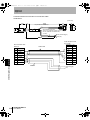
V500-R521C2 (Connector output type)
(Pin alignment)
Section 2 Wiring
Connector part (DIN: 8P plug)
Made by Hosiden Corporation
TCP1394-715267 (TypeA)
Pin No.
Signal
name
Function
1
SD
Transmission data
2
RD
Received data
3
RS
Transmission request
4
CS
Transmission allowed
5
TRIG
External trigger signal
6
NC
Not connected
7
S.GND
0V
8
VCC
Power supply
Signal direction
Bar code reader
Upper equipment
External
External
Connection with upper equipment p.88, p.89
When you make a connection cable, use the following connectors.
Recommended parts for the connector
Usage
Manufacturer
Model
For cable relay
Hosiden Corporation
TCS8587-0170477
For panel installation 2 Hosiden Corporation
TCS1080-0120177
Logic of external trigger signal can be selected.
Positive logic
(HIGH active)
Negative logic
(LOW active)
Trigger ON
Trigger ON
Setting method p.57
You can select the output logic of READ OK and READ NG signal.
Power supply
Recommended parts for the power supply
30
Manufacturer
Model
OMRON Corporation
S8VS-01505
V500-R521B2/C2
User’s Manual
V500-R521.book
31 ページ
2008年7月18日 金曜日 午後1時1分
Section 2
Wiring and Installation
Input/output circuit
Input circuit for the external trigger signal (Common to V500R521B2/V500-R521C2)
Vcc
Section 2 Wiring
External trigger signal
Vcc
Internal
circuit
TRIG
Von/off
SG
Item
Minimum
value
Maximum
value
Terminal voltage Von when a
transistor is turned on
0V
1.3 V
Terminal voltage Voff when a
transistor is turned off
2.5 V
Vcc
Output circuit of the READ OK/NG signal (Only V500-R521B2)
OK/NG
Internal
circuit
SG
Item
Specification
Output system
NPN open collector
Rated load
24 VDC 30 mA
Leak current at OFF
0.5 mA or less
Residual voltage at ON
1.0 V or less
Cable specification
• Shape:
Straight cable
• Diameter:
φ3.8 ± 0.5 mm
• Length:
2000 ± 50 mm
• Number of core: 9
V500-R521B2/C2
User’s Manual
31
V500-R521.book
32 ページ
2008年7月18日 金曜日 午後1時1分
Section 2
Wiring and Installation
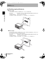
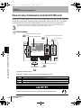
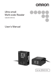
Installation
To avoid regular reflection of laser, incline approx. 15 ° against the bar code subject to read
when installing the bar code reader. Use this mounting bracket as the mounting surface of an
associated mounting bracket is inclined 15 °. (Tightening torque 0.54 N/m)
V500-R521
Section 2 Installation
V500-R521
1. Attach the mounting bracket on the bar code reader.
2. Install.
When you attach this line of the bracket
horizontally, the bar code reader inclines 15 °.
When you attach this line of the bracket vertically,
the bar code reader inclines 15 °.
Vertical
Horizontal
• When inductive noise is generated at the mounting bracket, attach an associated insulation board.
Use the associated screw to install the insulation board.
• Do not apply stress on the cable when installing or using.
• Distance and angle allowed to read differs according the bar code. Check if the used bar code can
be read actually, before installing.
32
V500-R521B2/C2
User’s Manual
V500-R521.book
33 ページ
2008年7月18日 金曜日 午後1時1分
Section 2
Wiring and Installation
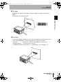
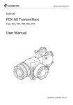
External dimension
Mounting bracket (accessory)
Material: SUS304
(Unit: mm)
Small screw, +Flat head 2-M3X 6
Mounting
bracket
Section 2 Installation
Light axis
Dimension of mounting hole
Bar code label
Laser beam
Insulation board (accessory)
Material: Fabric bake
(Unit: mm)
2-M5 holes
When the associated mounting bracket and insulation board are not used, install it by referring to the
outline dimension figure.
p.114
V500-R521B2/C2
User’s Manual
33
V500-R521.book
34 ページ
2008年7月18日 金曜日 午後1時1分
Section 2
Wiring and Installation
MEMO
Section 2 Installation
34
V500-R521B2/C2
User’s Manual
V500-R521.book
35 ページ
2008年7月18日 金曜日 午後1時1分
Section 3
Function Explanation
This section explains about representative functions of the bar code reader.
36
Operation Flow Chart
38
Communication Data Format
46
Test Reading Function
49
V500-R521B2/C2
User’s Manual
Section 3 Function Explanation
Explanation of Reading System
35
V500-R521.book
36 ページ
2008年7月18日 金曜日 午後1時1分
Section 3
Function Explanation
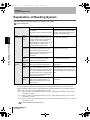
Explanation of Reading System
There are following reading systems for this bar code reader.
Setting method p.67
Reading system
Trigger reading
Full-time reading
Reading starts by applying reading trigger
During the power is turned on, laser is
from outside.
radiated all the time, to be able to read
This system is mainly used when operation. any time. This system is mainly used at
installation and system testing.
Section 3 Explanation of Reading System
Trigger
External
Input method trigger
signal
Reading
operation
(*2)
–
When the external trigger signal is turned
(Ignored even when input.)
on, laser radiates and starts reading. The
"Trigger controlled system" reads during
the trigger is ON, and the "Effective
duration designation system" reads only the
effective duration (*1) which is set
beforehand after the trigger is ON.
RS-232C
command
The upper equipment sends the
–
communication command and the laser
(Ignored even when input.)
beam radiates to start reading. After
receiving the command, it reads only for the
effective duration (*1) which is set
beforehand.
TEST
button
(Back side)
Press the TEST button once to read once.
Handy to use to check if the reading
condition setting is appropriate.
–
(Ignored even when pressed.)
Single
reading
When the reading succeeds, the data is
output and ends reading automatically.
Reads continuously and outputs the data
continuously.
Plural
reading
Reads bar codes continuously during the
trigger is ON or effective duration (*1).
When the first reading is completed, data is
once output and while reading the same
bar codes continuously, no output is made.
Outputs newly only when the data differ
from the adjacent bar code.
The bar code reading continues in series.
While reading the same bar code, output
is not newly made. Outputs newly only
when the data differ from the adjacent bar
code.
Continuous Reads bar codes continuously during the
reading
trigger is ON or effective duration (*1).
Outputs data continuously even for the
same bar code.
*1
Reads continuously and outputs the data
continuously.
Effective duration of reading
When the trigger input method is external trigger signal effective duration designation system or RS-232C
command, effective duration setting is required beforehand. Effective duration is set by combining "effective
duration" from 0 to 10 sec. and "minor setting" from 0 to 750 ms.
E.g. 1: When you want to set the effective duration to 2.5 sec., set the effective duration to 2 sec. and the
minor setting to 500 ms.
E.g. 2: When you want to set the effective duration to 0.7 sec., set the effective duration to 0 sec. and the
minor setting to 700 ms.
E.g. 3: When you want to set the effective duration to 10.0 sec., set the effective duration to 10 sec. and the
minor setting to 0 ms.
Effective duration setting method p.70
36
V500-R521B2/C2
User’s Manual
V500-R521.book
37 ページ
2008年7月18日 金曜日 午後1時1分
Section 3
Function Explanation
*2
Reading operation
Presence of the READ OK/NG signal output differs according to the reading operation setting.
(READ OK/NG signal output is only for V500-R521B1)
In case of single reading and plural reading:
When reading succeeded: OK signal is output.
When reading failed:
NG signal is output.
In case of continuous reading:
OK or NG signal after reading is not output.
READ OK/NG signal output p.28
Section 3 Explanation of Reading System
V500-R521B2/C2
User’s Manual
37
V500-R521.book
38 ページ
2008年7月18日 金曜日 午後1時1分
Section 3
Function Explanation
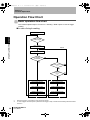
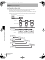
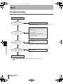
Operation Flow Chart
Basic operation flow chart
This clause explains steps of "Power on > Reading > Data output" in case of trigger
reading.
In case of single reading
Power on
Section 3 Operation Flow Chart
Wait for the
reading trigger
Laser radiation
Repeat
Reading process execution
Is reading
succeeded?
Is reading trigger end?
(*1)
Has reading
effective duration
passed?
(*2)
Laser beam goes out
Laser beam goes out
READ OK LED illuminates
READ NG LED illuminates
Reading data output
Process when reading failed
Repeat
Repeat
Process when reading succeeded
*1
When the trigger by a command is used, ignore this clause.
*2
In case of trigger controlled system (reads while the trigger is ON), consider that the reading effective duration
is set to 0.
38
Process when reading failed
V500-R521B2/C2
User’s Manual
V500-R521.book
39 ページ
2008年7月18日 金曜日 午後1時1分
Section 3
Function Explanation
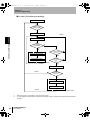
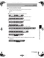
In case of plural reading
Power on
Wait for the
eading trigger
Laser radiation
Repeat
Section 3 Operation Flow Chart
Reading process execution
Is reading
succeeded?
Is the data
differ from the previous
reading?
READ OK LED illuminates
Reading data output
Is reading trigger end?
(*1)
Has reading effective
duration passed?
(*2)
Laser beam goes out
Process when reading succeeded
Repeat
Is reading
succeeded even just
once?
READ NG LED illuminates
Process when reading failed
Repeat
Process when reading failed
*1
When the trigger by a command is used, ignore this clause.
*2
In case of trigger controlled system (reads while the trigger is ON), consider that the reading effective duration
is set to 0.
V500-R521B2/C2
User’s Manual
39
V500-R521.book
40 ページ
2008年7月18日 金曜日 午後1時1分
Section 3
Function Explanation
In case of continuous reading
Power on
Wait for the
reading trigger
Laser radiation
Repeat
Section 3 Operation Flow Chart
Reading process execution
Is reading
succeeded?
Is reading trigger
end? (*1)
READ OK LED illuminates
Reading data output
Process when reading
succeeded
Has reading
effective duration
passed?
(*2)
Laser beam goes out
Repeat
Is reading
succeeded even
just once?
READ NG LED illuminates
Process when reading failed
Repeat
*1
When the trigger by a command is used, ignore this clause.
*2
In case of trigger controlled system (reads while the trigger is ON), consider that the reading effective duration
is set to 0.
40
Process when reading failed
V500-R521B2/C2
User’s Manual
V500-R521.book
41 ページ
2008年7月18日 金曜日 午後1時1分
Section 3
Function Explanation
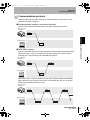
Communication protocol
There are following two types of system to transmit the data read by the bar code
reader to the upper equipment.
Nonprocedural system (no protocol system)
The bar code reader transmits the data to the upper equipment and ends.
Bar code reader
V500-R521
Data
End
ACK/NAK system
This bar code reader waits for the upper equipment response after transmitting the data.
When ACK (06H) 1 byte is received from the upper equipment, buzzer sounds
indicating the normal finishing and ends data transmission.
Bar code reader
V500-R521
Data
Section 3 Operation Flow Chart
Upper equipment
End
Upper equipment
When NAK (15H) 1 byte is received from the upper equipment data is transmitted
again. When the time-up time comes which is set beforehand, the time-up buzzer
sounds and the data transmission ends.
Bar code reader
V500-R521
Data
Data
Data
Upper equipment
V500-R521B2/C2
User’s Manual
41
V500-R521.book
42 ページ
2008年7月18日 金曜日 午後1時1分
Section 3
Function Explanation
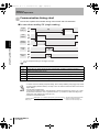
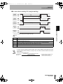
Communication timing chart
This section explains the indication timing of the buzzer and LED indication.
In case when reading OK (single reading)
Trigger
input (*1)
Laser
radiation
Section 3 Operation Flow Chart
Reading
operation
Reading
Buzzer,
LED
Communication
*1
You can change the setting for the trigger input logic.
p.53
Time
Description
T0
Trigger ON time. (When effective duration is designated, consider it as effective duration.)
T1
Chattering prevention time. (5 ms)
T2
Buzzer and indication LED illumination time. (Initial value: 200 ms, changing allowed)
T3
Trigger signal minimum OFF time. Be sure to set 30 ms or more.
T4
Communication time. Differs according to communication condition.
• In case of continuous reading and plural reading, laser is always radiating during trigger input is ON
(or during reading effective duration). Concept of T0 to T4 other than this is the same as the case of
single reading.
• A rough guide of reading time
As this bar code reader is approx. 500 decode/sec., decode process time for once is 2 ms. In case
of plural time conformance, "2 ms x (conformance time + 1)". However, it differs according to the
reading bar code condition (dirt or thin spot, etc.)
• Concept of communication time
Communication (Data length) + (1: In case when parity exists) + (Number of stop bit) (Number of digit of transmission data +
x Number of header characters +
time (ms) =
(Communication speed)
Number of footer characters) x 103
42
V500-R521B2/C2
User’s Manual
V500-R521.book
43 ページ
2008年7月18日 金曜日 午後1時1分
Section 3
Function Explanation
In case when reading NG (single reading)
Trigger
input (*1)
Laser
radiation
Reading
operation
Reading
Communication
*1 You can change the setting for the trigger input logic.
p.57
Time
T0
Description
Trigger ON time. (When effective duration is designated, consider it as effective duration.)
T1
Chattering prevention time (5 ms)
T2
Buzzer and indication LED illumination time. (Initial value: 200 ms, changing allowed)
T3
Trigger signal minimum OFF time. Be sure to set 30 ms or more.
T4
Communication time. Differs according to communication condition.
Section 3 Operation Flow Chart
Buzzer,
LED
• In case of continuous reading and plural reading, laser is always radiating during trigger input is ON
(or during reading effective duration). Concept of T0 to T4 other than this is the same as the case of
single reading.
• Concept of communication time
Communication
time (ms) =
(Data length) + (1: In case when parity exists) +
(Number of stop bit)
(Communication speed)
(Number of digit of transmission data +
x Number of header characters +
Number of footer characters) x 103
V500-R521B2/C2
User’s Manual
43
V500-R521.book
44 ページ
2008年7月18日 金曜日 午後1時1分
Section 3
Function Explanation
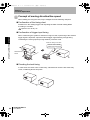
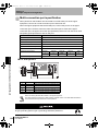
Concept of moving direction/line speed
When reading a moving bar code, fully investigate from the following viewpoint.
Confirmation of the timing chart
Duration from the reading trigger and outputting the data of actual reading differs
according to condition.
Operation Flow Chart p.38
Confirmation of trigger input timing
When constructing the system to read the moving bar code, input timing of the external
Section 3 Operation Flow Chart
trigger signal is important. Input the external trigger signal allowing enough timing
considering the moving speed (moving distance) of the bar code.
When the timing is too slow...
The bar code is already
passed and cannot read.
Photoelectronic
sensor
Checking the tack timing
In case when bar codes come continuously, calculate how close the bar codes may
come, considering above two points.
44
V500-R521B2/C2
User’s Manual
V500-R521.book
45 ページ
2008年7月18日 金曜日 午後1時1分
Section 3
Function Explanation
Moving direction of a bar code
Stability of reading differs according to the moving direction against the scanning
direction.
As the appropriate direction differs according to the size of a label, investigate when
installing.
Scanning direction
Section 3 Operation Flow Chart
Bar code moving direction
Scanning range
Whole height of a bar code
is scanned.
In case of tall size label, this
direction is stable.
A part of the height
of a bar code is
scanned.
In case of short
size label, this
direction is stable.
V500-R521B2/C2
User’s Manual
45
V500-R521.book
46 ページ
2008年7月18日 金曜日 午後1時1分
Section 3
Function Explanation
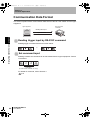
Communication Data Format
This section explains about communication data format of the bar code reader and the upper
equipment.
Bar code reader
V500-R521
Upper equipment
Reading data output
Input command
Section 3 Communication Data Format
Reading trigger input by RS-232C command
Reading trigger command format is as shown below.
or
.
Set command input
Reading condition set command can be transmitted from the upper equipment. Format
is as follows.
Command
(In case of one character, m1 only)
For details of command, refer to Section 4.
p.56
46
V500-R521B2/C2
User’s Manual
V500-R521.book
47 ページ
2008年7月18日 金曜日 午後1時1分
Section 3
Function Explanation
Data output format when reading succeeded
When bar code reading is succeeded, following data is transmitted to the upper
equipment.
Header Number
Data of read bar code
Output item
Number of
digit
Footer
Description
Initial setting
Letter strings to add at the head of transmitted data.
Max 4 arbitrary characters can be set.
No header
Number of digit of the read data is output in two-digit ASCII code.
Whether or not to output the number of digit is selectable.
No number of digit
output
Letter strings to add at the end of transmitted data.
Max 4 arbitrary characters can be set.
CR (0DH)
Setting methods of whether to output header, number of digit and footer p.79
Process when reading failed
Output format differs according to what is set to "reading failed process".
Selection of output format when reading failed
No process
Remarks
Nothing is transmitted
BR [CR] is transferred
[STX]?[ETX], [STX]>[ETX] is transferred
?[CR], >[CR] are transferred
–
?:
>:
When it is judged as no bar code
In cases other than above
[CAN] [CR] are transferred
–
[STX] [CAN] [ETX] are transferred
–
Section 3 Communication Data Format
Header
Footer
Setting method p.68
V500-R521B2/C2
User’s Manual
47
V500-R521.book
48 ページ
2008年7月18日 金曜日 午後1時1分
Section 3
Function Explanation
Data transfer contents of each reading code type
Reading code
Section 3 Communication Data Format
UPC-A
You can select whether or not to transfer the head character "0" for
transfer digit number adjustment and check digit C/D. ("0" is the
additional character combining with C/D to adjust the number of digit to
be in accordance with EAN-13.)
0 S X1 X2 X3 X4 X5 X6 X7 X8 X9 X10 C/D
S: Number system character (Automatically decided according to the
combination of each character of X1 to X10.)
UPC-E
You can select whether or not to transfer the head character "0" for
transfer digit number adjustment and check digit C/D. ("0" is the
additional character combining with C/D to adjust the number of digit to
be in accordance with EAN-13.)
0 S X1 X2 X3 X4 X5 X6 C/D
S: Number system character (Automatically decided according to the
combination of each character of X1 to X10.)
EAN
Reading data (8-digit or 13-digit) is transferred as it is.
ITF, STF (2 of 5 bar)
Transfers in the order from the next character of the start code to the
character before the stop code. (Start code and stop code are not
transferred.)
NW-7, CODE39
You can select whether or not to transfer the start code and stop code.
When the start code and stop code is permitted to transfer, you can
select whether the transferred start/stop code of NW-7 is in lower-case
"a/b/c/d" or in upper-case "A/B/C/D".
Transfer start/stop code of CODE39 is "*".
EAN128
Add a control character "C1" (ASCII code 5D, 43, 31) which indicates
EAN 128, at the head of the transfer data. Also, FNC1 character, as a
separating character, is replaced to GS (ASCII code 1DH) character
and transferred.
Setting method p.63
48
Description
V500-R521B2/C2
User’s Manual
V500-R521.book
49 ページ
2008年7月18日 金曜日 午後1時1分
Section 3
Function Explanation
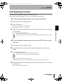
Test Reading Function
You can check how stably the subject bar code can be read.
Read a bar code at resting state for one sec. and calculate the reading rate.
To enter reading measurement mode using a command
1. Install the bar code at a reading position.
2. Enter command "7U".
Reading rate of every one sec. is measured.
3. To finish the reading rate measurement mode, enter reset command "Z1" or re-start the
bar code reader.
Return to the normal measurement mode.
Do not execute write command "Z2" to nonvolatile memory.
A sample setting condition is overwritten and stored, which erases the already set reading condition.
To enter reading measurement mode using a TEST button on the
back side
Section 3 Test Reading Function
Mode enters to reading rate measurement mode.
1. Install the bar code at a reading position.
2. Keep pressing the TEST button until the buzzer (tones repeating "Sol" and "Do")
sounds.
3. Press the TEST button once.
Press the TEST button within 10 sec. after the buzzer sounds.
After 10 sec. or more have passed, it returns to the original state.
Mode entered to reading rate measurement mode.
(Reading rate of every one sec. is measured according to the reading condition of factory default.)
4. To finish the reading rate measurement mode, enter reset command "Z1" or re-start the
bar code reader.
Return to the normal measurement mode.
V500-R521B2/C2
User’s Manual
49
V500-R521.book
50 ページ
2008年7月18日 金曜日 午後1時1分
Section 3
Function Explanation
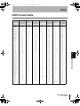
Output format
Reading rate of every one sec. is output to the upper equipment, while in reading rate
measurement mode.
Number of decoded time in one sec.
Of those, correct reading data (*) detected rate = Reading rate
Correct reading data (*)
Data, which detected most during measurement mode, is “correct reading data”.
Section 3 Test Reading Function
Communication data format
A rough guide of reading rate
The LED illumination patter on the back side changes according to the result of reading
rate.
Reading rate
READ NG LED
READ OK LED
Description
Reading is possible without problem.
76~100 %
51~75 %
When the bar code is at still state when read,
reading is possible without problem.
However, when the target bar code is moving,
reading may be failed according to speed.
26~50 %
There is a possibility to fail even reading at still
state. Check if the installation location and angle of
the bar code reader is appropriate once more.
0~25 %
Reading is not stable. Check if there is no dirt or
lack on the bar code.
Check if the installation location and angle of the
bar code reader is appropriate once more.
LED indication
: Lights out
50
V500-R521B2/C2
User’s Manual
: Blink
: Illuminate
V500-R521.book
51 ページ
2008年7月18日 金曜日 午後1時1分
Section 4
Setting Method
This section explains about setting methods using a menu sheet and entering
command from the upper equipment.
52
Menu Sheet/Command List
56
V500-R521B2/C2
User’s Manual
Section 4 Setting Method
How to Use Menu Sheet/Command
51
V500-R521.book
52 ページ
2008年7月18日 金曜日 午後1時1分
Section 4
Setting Method
How to Use Menu Sheet/Command
There are following two setting methods for the bar code reader. Select either method
according to the condition.
Setting method
Description
Read the menu sheet.
This method reads the menu sheet of the function you want to set.
It is convenient for the initial setting and when testing.
Input a command from the upper
equipment.
This method inputs a command from the upper equipment.
It is convenient when changing setup according to the type of the bar
code.
Read the menu sheet
Section 4 How to Use Menu Sheet/Command
The menu sheet is a special bar code used to set this bar code function.
Setting can be changed by reading this menu sheet.
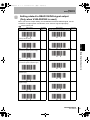
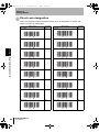
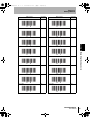
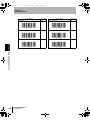
1. Read "Z7" of the menu sheet that means setting start/end.
Buzzer sounds continuously.
The bar code reader entered setting mode.
2. Read "UA" on the menu sheet that means to return to factory default setting.
3. Read the item on the menu sheet you want to change setting.
Menu Sheet/Command List p.56
4. To finish setting, read "Z7" on the menu sheet for setting start/end, again.
Buzzer sound stops and returns to normal mode.
52
V500-R521B2/C2
User’s Manual
V500-R521.book
53 ページ
2008年7月18日 金曜日 午後1時1分
Section 4
Setting Method
How to create menu sheet
The used menu sheet is a code system of CODE39. However, the code is special,
using start code and stop code for a space mark. (Normally "*")
You can create a menu sheet using bar code creation software available in the market,
as shown below.
E.g.: When creating a menu sheet "A3"
Create "* A3 *" and cut the parts of "*" with scissors to create the menu sheet "A3".
Cutting off section
Cutting off section
Section 4 How to Use Menu Sheet/Command
V500-R521B2/C2
User’s Manual
53
V500-R521.book
54 ページ
2008年7月18日 金曜日 午後1時1分
Section 4
Setting Method
Input command from the upper equipment
Bar code reader
V500-R521
Upper equipment
Transmit command character strings.
1. Transmit the command character strings of the function you want to set.
Section 4 How to Use Menu Sheet/Command
54
Command
(In case of one character, m1 only)
Menu Sheet/Command List p.56
During the bar code reader is processing command, it notifies externally that it is in processing
mode turning off the RS signal line.
When the RS signal line is not connected, interval between inputting commands should be taken
sufficiently.
2. Transmits "Z2", in order to write the set data on the nonvolatile memory in the bar code
reader.
Be sure to write when a condition is set by inputting command from the upper equipment. When you
turn off the power without writing the setting in the memory, the set content may be deleted.
V500-R521B2/C2
User’s Manual
V500-R521.book
55 ページ
2008年7月18日 金曜日 午後1時1分
Section 4
Setting Method
Transmission method of the command by designating values and characters is
explained as follows.
E.g. 1: Set "AB [CR]" on header. (When designating codes directly)
Transmit a header setting command.
Transmit a character "A".
Transmit a character "B".
Transmit CR code.
Transmit a header setting command.
Transmit 41 "A" in hexadecimal number.
Transmit 42 "B" in hexadecimal number.
Transmit CR code.
"00H" (zero) cannot be designated as header or footer. It is regarded as end character.
Characters until just before 00H are valid.
Section 4 How to Use Menu Sheet/Command
E.g. 2: Set "AB [CR]" on header. (When designating hexadecimal number directly)
E.g. 3: Reading number of digit is set to "8-digit" and "12-digit".
Transmit the number of digit command "A".
Transmit "8-digit". (Input in decimal number.
Numbers are fix to 2-digit.)
Transmit the number of digit command "B".
Transmit "12-digit". (Input in decimal number.
Numbers are fix to 2-digit.)
V500-R521B2/C2
User’s Manual
55
V500-R521.book
56 ページ
2008年7月18日 金曜日 午後1時1分
Section 4
Setting Method
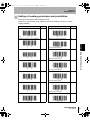
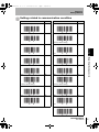
Menu Sheet/Command List
Groups are classified as follows. Please refer to the corresponding pages.
Setting item
Section 4 Menu Sheet/Command List
56
Reference
Setting start/end according to menu sheets
p.57
Write setting contents on the nonvolatile memory
p.57
Reset
p.57
Setting related to external trigger signal
p.57
Return to factory default setting
p.58
Collective setting
p.59
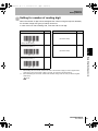
Setting of reading permission and prohibition
p.61
Detail setting for reading code
p.63
Setting for reading conformance
p.66
Setting for reading system
p.67
Setting for failed reading
p.68
Setting for number of reading digit
p.69
Setting for reading effective duration
p.70
Setting related to LED
p.72
Settings related to duration of buzzer sound and volume
p.73
Setting related to READ OK/NG signal output (Only when V500R521B2 is used)
p.75
Setting related to communication condition
p.77
Setting related to communication protocol
p.78
Setting for header, footer and number of reading digit
p.79
Setting related to test reading
p.79
Direct code designation
p.80
Setting related to sorting read
p.83
V500-R521B2/C2
User’s Manual
V500-R521.book
57 ページ
2008年7月18日 金曜日 午後1時1分
Section 4
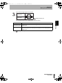
Setting Method
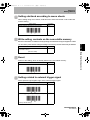
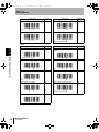
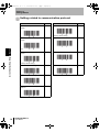
Setting start/end according to menu sheets
When setting using menu sheets, read this menu sheet with the bar code to start and
end the setting.
Menu sheet
Setting start/end according to menu sheets
Command
None
Write setting contents on the nonvolatile memory
Be sure to write when a condition is set by inputting command from the upper equipment. When
Menu sheet
Write the contents set with a command in the
nonvolatile memory.
(No menu sheet)
Command
Z2
Reset
Return to the setting, which is already written in the nonvolatile memory.
Menu sheet
Reset
Command
Z1
Section 4 Menu Sheet/Command List
you turn off the power without writing the setting in the memory, the set content may be deleted.
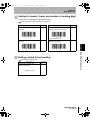
Setting related to external trigger signal
Select positive logic/negative logic of the external trigger signal.
Menu sheet
Command
External trigger signal Positive logic (H active)
8A
External trigger signal Negative logic (L active)
8B
(Factory default setting)
V500-R521B2/C2
User’s Manual
57
V500-R521.book
58 ページ
2008年7月18日 金曜日 午後1時1分
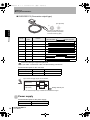
Section 4
Setting Method
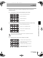
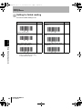
Return to factory default setting
Menu sheet
Command
Factory default setting
UA
Initial setting
Item
Setting content
Types of code, which is possible to read EAN/UPC, CODE39, NW-7, STF, ITF
J1+R4+B2+B3
+R7+R8
Number of reading digits
H0
No designated number of digits
Detail condition CODE39 detail setting Invalid C/D of CODE39
Section 4 Menu Sheet/Command List
Transfer C/D of CODE39
NW-7 detail setting
ITF/STF detail setting
Reading
condition
C0
C2
Transfer ST/SP of CODE39
D1
Invalid C/D of NW-7
F7
Transfer C/D of NW-7
F5
Transfer ST/SP of NW-7 (abcd/abcd)
F4
Invalid C/D of ITF/STF
G0
Transfer C/D of ITF/STF
G2
Reading system
Trigger reading
S8
Reading operation
Single reading
S0
Reading valid time
Trigger + 2 sec.
Y2
Number of reading
coincidence
Twice (Verification: once)
X1
Communication Communication speed 9600 bps
condition
Data length
8-bit
Parity
None
K6
L1
L2
Stop bit length
1-bit
L5
Header
None
1Y
Footer
CR
1Z+1C
Transfer number of
digits
Not transferred
2Z
RS/CS control
None
P0
CS waiting time
Infinity
I0
Communication
protocol
No protocol system
P5
Process when reading No process (Nothing is transferred)
is NG
58
Corresponding
command
5E
LED illumination
LED illumination time after decoding is 200 ms.
Buzzer sound
Buzzer sound duration after decoding is 200 ms. W5
Buzzer sound volume
Max.
T0
Buzzer frequency
3 kHz, 2 kHz
W2
External trigger signal
Negative logic (L active)
8B
READ OK/NG signal output
Output
8Q
READ OK/NG signal output system
Trigger synchronous system, positive logic
(H active)
8C
V500-R521B2/C2
User’s Manual
T5
V500-R521.book
59 ページ
2008年7月18日 金曜日 午後1時1分
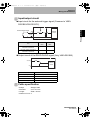
Section 4
Setting Method
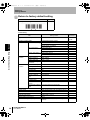
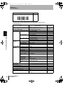
Collective setting
Collective setting of conditions appropriate for connection of programmable controller
(UB) and for connection of multi-drop using link unit (UC) is allowed.
Menu sheet
Command
Setting of programmable controller connection
UB
Hatching parts are the changed point from the factory default setting.
Collective setting
Item
Corresponding
command
Setting content
J1+R4+B2+B3
+R7+R8
Number of reading digits
H0
No designated number of digits
Detail condition CODE39 detail setting Invalid C/D of CODE39
NW-7 detail setting
ITF/STF detail setting
Reading
condition
C0
Transfer C/D of CODE39
C2
Transfer ST/SP of CODE39
D1
Invalid C/D of NW-7
F7
Transfer C/D of NW-7
F5
Transfer ST/SP of NW-7 (abcd/abcd)
F4
Invalid C/D of ITF/STF
G0
Transfer C/D of ITF/STF
G2
Reading system
Trigger reading
S8
Reading operation
Single reading
S0
Reading valid time
Trigger + 2 sec.
Y2
Number of reading
coincidence
Twice (Verification: once)
X1
Communication Communication speed 9600 bps
condition
7-bit
Data length
Section 4 Menu Sheet/Command List
Types of code, which is possible to read EAN/UPC, CODE39, NW-7, STF, ITF
K6
L0
Parity
Even number
Stop bit length
2-bit
L6
L6
Header
None
1Y
Footer
CR
1Z+1C
Transfer number of digits Not transferred
2Z
RS/CS control
None
P0
CS waiting time
Infinity
I0
Communication
protocol
No protocol system
P5
Process when reading is NG Transfer ? (CR), > (CR)
5H
LED illumination
LED illumination time after decoding is 200 ms.
T5
Buzzer sound
Buzzer sound duration after decoding is 200 ms. W5
Buzzer sound volume
Max.
T0
Buzzer frequency
3 kHz, 2 kHz
W2
External trigger signal
Negative logic (L active)
8B
READ OK/NG signal output
Output
8Q
READ OK/NG signal output system
Trigger synchronous system, positive logic
(H active)
8C
V500-R521B2/C2
User’s Manual
59
V500-R521.book
60 ページ
2008年7月18日 金曜日 午後1時1分
Section 4
Setting Method
Menu sheet
Command
Setting for connecting link unit (V700-L12)
UC
Hatching parts are the changed point from the factory default setting.
Collective setting
Item
Setting content
Types of code, which is possible to read EAN/UPC, CODE39, NW-7, STF, ITF
J1+R4+B2+B3
+R7+R8
Number of reading digits
H0
No designated number of digits
Section 4 Menu Sheet/Command List
Detail condition CODE39 detail setting Invalid C/Dof CODE39
Transfer C/D of CODE39
NW-7 detail setting
ITF/STF detail setting
Reading
condition
C0
C2
Transfer ST/SP of CODE39
D1
Invalid C/D of NW-7
F7
Transfer C/D of NW-7
F5
Transfer ST/SP of NW-7 (abcd/abcd)
F4
Invalid C/D of ITF/STF
G0
Transfer C/D of ITF/STF
G2
Reading system
Trigger reading
S8
Reading operation
Single reading
S0
Reading valid time
Trigger + 2 sec.
Y2
Number of reading
coincidence
Twice (Verification: once)
X1
Communication Communication speed 9600 bps
condition
Data length
8-bit
K6
L1
Parity
Even number
L3
Stop bit length
1-bit
L5
Header
None
1Y
Footer
CR
1Z+1C
Transfer number of
digits
Not transferred
2Z
RS/CS control
None
P0
CS waiting time
Infinity
I0
Communication
protocol
No protocol system
P5
Process when reading Transfer ? (CR), > (CR)
is NG
60
Corresponding
command
5H
LED illumination
LED illumination time after decoding is 200 ms.
Buzzer sound
Buzzer sound duration after decoding is 200 ms. W5
T5
Buzzer sound volume
Max.
T0
Buzzer frequency
3 kHz, 2 kHz
W2
External trigger signal
Negative logic (L active)
8B
READ OK/NG signal output
Output
8Q
READ OK/NG signal output system
Trigger synchronous system, positive logic
(H active)
8C
V500-R521B2/C2
User’s Manual
V500-R521.book
61 ページ
2008年7月18日 金曜日 午後1時1分
Section 4
Setting Method
Setting of reading permission and prohibition
Select bar code types of which subject to read.
Prohibit bar codes, which is not subject to read, from reading in order to increase
reading reliability.
Menu sheet
Reading permission only for UPC-A/E
Command
Menu sheet
Command
J1
Reading permission for UPC-A/E
R1
J4
Reading permission for EAN13/8
R4
(Factory default setting)
Reading permission only for EAN13/8
Reading permission only for CODE39
A2
Reading permission for CODE39
B2
(Factory default setting)
Reading permission only for NW-7
A3
Reading permission for NW-7
B3
(Factory default setting)
Reading permission only for ITF
J8
Reading permission for ITF
Section 4 Menu Sheet/Command List
(Factory default setting)
R8
(Factory default setting)
Reading permission only for STF
J7
Reading permission for STF
R7
(Factory default setting)
Reading permission only for CODE93
A5
Reading permission for CODE93
B5
V500-R521B2/C2
User’s Manual
61
V500-R521.book
62 ページ
2008年7月18日 金曜日 午後1時1分
Section 4
Setting Method
Menu sheet
Command
Reading permission only for CODE128 A6
Section 4 Menu Sheet/Command List
Reading prohibition for EAN/UPC
4A
Reading prohibition for CODE39
4H
Reading prohibition for NW-7
4I
Reading prohibition for STF
4K
Reading prohibition for ITF
4L
Reading prohibition for CODE93
4M
(Factory default setting)
Reading prohibition for CODE128
4N
(Factory default setting)
Reading prohibition for all types
62
V500-R521B2/C2
User’s Manual
4Z
Menu sheet
Reading permission for CODE128
Command
B6
V500-R521.book
63 ページ
2008年7月18日 金曜日 午後1時1分
Section 4
Setting Method
Detail setting for reading code
Conditions of detail reading code such as whether check digit (C/D) is used or start
code/stop code (ST/SP) is transmitted are set.
UPC-A
Menu sheet
Output UPC-A in 13-digit
Command
Menu sheet
Command
E2
Output UPC-A in 12-digit (without C/D)
E4
E3
Output UPC-A in 11-digit (without 0 in
the beginning or C/D)
E5
(Factory default setting)
Output UPC-A in 12-digit (without 0 in
the beginning)
Menu sheet
Output UPC-E in 8-digit
Command
E6
Menu sheet
Command
Output UPC-E in 7-digit (without C/D)
E8
(Factory default setting)
Output UPC-E in 7-digit (without 0 in
the beginning)
E7
Output UPC-E in 6-digit (without 0 in
the beginning or C/D)
E9
Section 4 Menu Sheet/Command List
UPC-E
CODE39
Menu sheet
Invalid C/D of CODE39
Command
Menu sheet
Command
C0
Not transfer ST/SP of CODE39
D0
C1
Transfer ST/SP of CODE39
D1
(Factory default setting)
Valid C/D of CODE39
(Factory default setting)
V500-R521B2/C2
User’s Manual
63
V500-R521.book
64 ページ
2008年7月18日 金曜日 午後1時1分
Section 4
Setting Method
Menu sheet
Transfer C/D of CODE39
Command
Menu sheet
Command
C2
CODE39 1-digit reading permission
7C
C3
CODE39 1-digit reading prohibition
7D
(Factory default setting)
Not transfer C/D of CODE39
(Factory default setting)
NW-7
Menu sheet
Section 4 Menu Sheet/Command List
Invalid C/D of NW-7
Command
Menu sheet
Command
F7
Transfer ST/SP of NW-7 (ABCD/
ABCD)
F3
F9
Transfer ST/SP of NW-7 (abcd/abcd)
F4
(Factory default setting)
Valid C/D of NW-7 (modulus 16)
(Factory default setting)
Transfer C/D of NW-7
F5
NW-7 1-digit reading permission
7K
F6
NW-7 1-digit reading prohibition
7L
(Factory default setting)
Not transfer C/D of NW-7
(Factory default setting)
Not transfer ST/SP of NW-7
64
V500-R521B2/C2
User’s Manual
F0
V500-R521.book
65 ページ
2008年7月18日 金曜日 午後1時1分
Section 4
Setting Method
ITF/STF
Menu sheet
Invalid C/D of ITF/STF
Command
Menu sheet
Command
G0
Not transfer C/D of ITF/STF
G3
Valid C/D of ITF/STF
G1
ITF/STF 2-digit reading permission
7M
Transfer C/D of ITF/STF
G2
ITF/STF 2-digit reading prohibition
7N
(Factory default setting)
(Factory default setting)
CODE128
After executing CODE128 reading permission command (B6), execute commands as shown below.
Menu sheet
All reading permission including
EAN128
Command
G5
Menu sheet
Command
Reading permission only for EAN128 in G6
CODE128
(Factory default setting)
Section 4 Menu Sheet/Command List
(Factory default setting)
EAN128 (Reading specification) p.126
V500-R521B2/C2
User’s Manual
65
V500-R521.book
66 ページ
2008年7月18日 金曜日 午後1時1分
Section 4
Setting Method
Setting for reading conformance
When decoded results coincide for the set number of conformance, the read results are
output to RS-232C interface.
Verification system is AND verification (Continuous conformance system). (Change
prohibition)
Menu sheet
Reading conformance twice
(Verification: once)
Command
Menu sheet
Command
X1
Reading conformance 5 times
(Verification: 4 times)
7R
Reading conformance 3 times
(Verification: 2 times)
X2
Reading conformance 6 times
(Verification: 5 times)
7S
Reading conformance 4 times
(Verification: 3 times)
X3
(Factory default setting)
Section 4 Menu Sheet/Command List
66
V500-R521B2/C2
User’s Manual
V500-R521.book
67 ページ
2008年7月18日 金曜日 午後1時1分
Section 4
Setting Method
Setting for reading system
Set the reading system.
Explanation of Reading System p.36
Reading system
Menu sheet
Full-time reading
Command
S7
Menu sheet
Trigger reading
Command
S8
(Factory default setting)
Menu sheet
Single reading
Command
S0
Menu sheet
Continuous reading
Command
S2
(Factory default setting)
Plural reading
S1
V500-R521B2/C2
User’s Manual
Section 4 Menu Sheet/Command List
Reading operation
67
V500-R521.book
68 ページ
2008年7月18日 金曜日 午後1時1分
Section 4
Setting Method
Setting for failed reading
Process for failed reading is set.
Menu sheet
Command
When reading failed: no process
Menu sheet
Command
5E
When reading failed: Transfer ? [CR],
>[CR] (*)
5H
When reading failed: Transfer BR [CR]
5F
When reading failed: Transfer [CAN]
[CR]
5I
When reading failed: Transfer
[STX]?[ETX], [STX]>[ETX] (*)
5G
When reading failed: Transfer [STX]
[CAN] [ETX]
5J
(Factory default setting)
Section 4 Menu Sheet/Command List
68
*
When it is judged as no bar code:?
In cases other than above:
V500-R521B2/C2
User’s Manual
>
V500-R521.book
69 ページ
2008年7月18日 金曜日 午後1時1分
Section 4
Setting Method
Setting for number of reading digit
When the number of digit is fixed, designate the number of digit to improve reliability.
For number of digit, two types (A and B) can be set.
In case of the bar code including C/D, count the C/D as one digit.
Menu sheet
Number of digit is not designated.
Command
None
Menu sheet
Command
Designation of number of digit A *2
7V
(No menu sheet)
(Factory default setting)
Designation of number of digit A (Bar
code reading system) *1
None
Designation of number of digit B *2
7W
Designation of number of digit B (Bar
code reading system) *1
None
*1
After reading this menu sheet, read the bar code of the number of digit you want to register twice,
*2
After transmitting this command, transmit the character string of the bar code you want to register,
continuously. When the number of digit is one type, set A and B to the same setting.
continuously.
Section 4 Menu Sheet/Command List
(No menu sheet)
p.54
V500-R521B2/C2
User’s Manual
69
V500-R521.book
70 ページ
2008年7月18日 金曜日 午後1時1分
Section 4
Setting Method
Setting for reading effective duration
After inputting a trigger, set the time for the continuous reading. Effective duration is set
by combining "effective duration" from 0 to 10 sec. and "minor setting" from 0 to 750 ms.
This is set only in case when the reading system, which is required to set the effective
duration, is selected.
Explanation of Reading System p.36
Menu sheet
Coupled with trigger (trigger + 0 sec.)
Command
Y0
Menu sheet
Trigger +0 ms (minor setting)
Command
YA
(Factory default setting)
Section 4 Menu Sheet/Command List
70
Trigger + 1 sec.
Y1
Trigger + 5.0 ms (minor setting)
YB
Trigger + 2 sec.
Y2
Trigger + 100 ms (minor setting)
YC
Trigger + 3 sec.
Y3
Trigger + 150 ms (minor setting)
YD
Trigger + 4 sec.
Y4
Trigger + 200 ms (minor setting)
YE
Trigger + 6 sec.
Y5
Trigger + 250 ms (minor setting)
YF
Trigger + 8 sec.
Y6
Trigger + 300 ms (minor setting)
YG
(Factory default setting)
V500-R521B2/C2
User’s Manual
V500-R521.book
71 ページ
2008年7月18日 金曜日 午後1時1分
Section 4
Setting Method
Menu sheet
Command
Menu sheet
Command
Y7
Trigger + 350 ms (minor setting)
YH
Trigger + 400 ms (minor setting)
YI
Trigger + 600 ms (minor setting)
YM
Trigger + 450 ms (minor setting)
YJ
Trigger + 650 ms (minor setting)
YN
Trigger + 500 ms (minor setting)
YK
Trigger + 700 ms (minor setting)
YO
Trigger + 550 ms (minor setting)
YL
Trigger + 750 ms (minor setting)
YP
V500-R521B2/C2
User’s Manual
Section 4 Menu Sheet/Command List
Trigger + 10 sec.
71
V500-R521.book
72 ページ
2008年7月18日 金曜日 午後1時1分
Section 4
Setting Method
Setting related to LED
When reading succeeded, READ OK LED illuminates and when reading failed, READ
NG LED illuminates. Duration of illumination is allowed to set.
Menu sheet
Section 4 Menu Sheet/Command List
72
Command
Menu sheet
Command
LED does not illuminate after decode.
T4
The LED illuminates for 400 ms after
decoding.
T6
The LED illuminates for 100 ms after
decoding.
T8
The LED illuminates for 800 ms after
decoding.
T7
The LED illuminates for 200 ms after
decoding.
T5
(Factory default setting)
V500-R521B2/C2
User’s Manual
V500-R521.book
73 ページ
2008年7月18日 金曜日 午後1時1分
Section 4
Setting Method
Settings related to duration of buzzer sound and volume
When reading succeeded, buzzer sounds. Sound volume, frequency and duration of
the buzzer are allowed to set.
(When sorting read function is used, buzzer sounds when reading result is disagree
with the registered data.)
Buzzer sound volume
Menu sheet
Buzzer sound volume; max.
Duration of buzzer
Command
Menu sheet
Command
T0
Buzzer sound duration after decoding;
10 ms
W8
Buzzer sound volume; middle or above T1
Buzzer sound duration after decoding;
50 ms
W7
Buzzer sound volume; middle or below
T2
Buzzer sound duration after decoding;
100 ms
W4
Buzzer sound volume; min.
T3
Buzzer sound duration after decoding;
200 ms
W5
(Factory default setting)
Section 4 Menu Sheet/Command List
(Factory default setting)
No buzzer sound after decoding
W0
Buzzer sound duration after decoding;
400 ms
W6
V500-R521B2/C2
User’s Manual
73
V500-R521.book
74 ページ
2008年7月18日 金曜日 午後1時1分
Section 4
Setting Method
Buzzer frequency
Menu sheet
Buzzer sound frequency after
decoding; 3 kHz
W1
Buzzer sound frequency after
decoding; 3 kHz, 2 kHz
W2
(Factory default setting)
Section 4 Menu Sheet/Command List
74
Command
V500-R521B2/C2
User’s Manual
Menu sheet
Buzzer sound frequency after
decoding; 2 kHz, 3 kHz
Command
W3
V500-R521.book
75 ページ
2008年7月18日 金曜日 午後1時1分
Section 4
Setting Method
Setting related to READ OK/NG signal output
(Only when V500-R521B2 is used)
When you want to output reading succeeded/failed to READ OK/NG signal, set the
conditions of output system and duration, then execute "signal output (8Q)".
Output system p.28
Menu sheet
Signal output
Command
Menu sheet
Command
8Q
Signal output one-shot duration; 30 ms
8I
No signal output
8R
Signal output one-shot duration; 40 ms
8J
Signal output trigger signal
synchronous system (positive logic)
8C
Signal output one-shot duration; 50 ms
8K
Signal output trigger signal
synchronous system (negative logic)
8D
Signal output one-shot duration; 60 ms
8L
Signal output one-shot system
(positive logic)
8E
Signal output one-shot duration; 70 ms
8M
Signal output one-shot system
(negative logic)
8F
Signal output one-shot duration; 80 ms
8N
Signal output one-shot duration; 10 ms
8G
Signal output one-shot duration; 90 ms
8O
(Factory default setting)
V500-R521B2/C2
User’s Manual
Section 4 Menu Sheet/Command List
(Factory default setting)
75
V500-R521.book
76 ページ
2008年7月18日 金曜日 午後1時1分
Section 4
Setting Method
Menu sheet
Signal output one-shot duration 20 ms
Section 4 Menu Sheet/Command List
76
V500-R521B2/C2
User’s Manual
Command
8H
Menu sheet
Signal output one-shot duration; 100 ms
Command
8P
V500-R521.book
77 ページ
2008年7月18日 金曜日 午後1時1分
Section 4
Setting Method
Setting related to communication condition
Menu sheet
Command
Menu sheet
Command
Communication speed; 300 bps
K1
Data length; 7-bit
L0
Communication speed; 600 bps
K2
Data length; 8-bit
L1
(Factory default setting)
Communication speed; 1200 bps
K3
No parity
L2
Communication speed; 2400 bps
K4
Parity even number
L3
Communication speed; 4800 bps
K5
Parity uneven number
L4
Communication speed; 9600 bps
K6
Stop bit; 1-bit
L5
Communication speed; 19200 bps
K7
Stop bit; 2-bit
L6
Communication speed; 38400 bps
K8
Without RS/CS control
P0
(Factory default setting)
Section 4 Menu Sheet/Command List
(Factory default setting)
(Factory default setting)
(Factory default setting)
With RS/CS control (BUSY/READY)
P1
V500-R521B2/C2
User’s Manual
77
V500-R521.book
78 ページ
2008年7月18日 金曜日 午後1時1分
Section 4
Setting Method
Setting related to communication protocol
Menu sheet
Communication protocol: ACK/NAK
system
Command
P3
Menu sheet
CS waiting time: Infinite
Command
I0
(Factory default setting)
P5
CS waiting time: 100 ms
I1
I4
CS waiting time: 200 ms
I2
ACK/NAK response waiting time: 100 ms I5
CS waiting time: 400 ms
I3
Communication protocol: No protocol
system
Section 4 Menu Sheet/Command List
(Factory default setting)
ACK/NAK response waiting time:
Infinite
(Factory default setting)
ACK/NAK response waiting time: 500 ms I6
ACK/NAK response waiting time:
1000 ms
78
V500-R521B2/C2
User’s Manual
I7
V500-R521.book
79 ページ
2008年7月18日 金曜日 午後1時1分
Section 4
Setting Method
Setting for header, footer and number of reading digit
Format when outputting the reading result is set.
Data output format when reading succeeded p.47
Menu sheet
Collective setting of header (Applied to
all codes)
Command
1Y
Menu sheet
Command
Number of reading digit is not
transferred (Applied to all codes)
2Z
(Factory default setting)
Collective setting of footer (Applied to
all codes)
1Z
Number of reading digit is transferred
(Applied to all codes)
3Z
Section 4 Menu Sheet/Command List
Setting related to test reading
Test reading function p.49
Menu sheet
Mode enters to reading rate
measurement mode.
Command
7U
(No menu sheet)
V500-R521B2/C2
User’s Manual
79
V500-R521.book
80 ページ
2008年7月18日 金曜日 午後1時1分
Section 4
Setting Method
Direct code designation
Use to set character strings and values directly such as designation of header and
footer or number of reading digit.
Menu sheet
Section 4 Menu Sheet/Command List
80
Command
Menu sheet
Command
"A" is set.
0A
"I" is set.
0I
"B" is set.
0B
"J" is set.
0J
"C" is set.
0C
"K" is set.
0K
"D" is set.
0D
"L" is set.
0L
"E" is set.
0E
"M" is set.
0M
"F" is set.
0F
"N" is set.
0N
"G" is set.
0G
"O" is set.
0O
"H" is set.
0H
"P" is set.
0P
V500-R521B2/C2
User’s Manual
V500-R521.book
81 ページ
2008年7月18日 金曜日 午後1時1分
Section 4
Setting Method
Menu sheet
Command
Menu sheet
Command
0Q
"Z" is set.
0Z
"R" is set.
0R
"0" is set.
Q0
'"S" is set.
0S
"1" is set.
Q1
"T" is set.
0T
"2" is set.
Q2
"U" is set.
0U
"3" is set.
Q3
"V" is set.
0V
"5" is set.
Q5
"W" is set.
0W
"6" is set.
Q6
"Y" is set.
0Y
"7" is set.
Q7
V500-R521B2/C2
User’s Manual
Section 4 Menu Sheet/Command List
"Q" is set.
81
V500-R521.book
82 ページ
2008年7月18日 金曜日 午後1時1分
Section 4
Setting Method
Menu sheet
Menu sheet
Command
"8" is set.
Q8
ETX (03H) is set.
1B
"9" is set.
Q9
CR (ODH) is set.
1C
STX (02H) is set
1A
LF (0AH) is set.
1D
Section 4 Menu Sheet/Command List
82
Command
V500-R521B2/C2
User’s Manual
V500-R521.book
83 ページ
2008年7月18日 金曜日 午後1時1分
Section 4
Setting Method
Setting related to sorting read
Bar code data to read are registered in this bar code reader beforehand and only the
registered bar codes are read using this function. When the read bar code does not
coincide with the registered data, buzzer sounds.
Up to 5 types of bar codes can be registered.
Menu sheet
Command
Register one character each using
command. (*1)
Register with regular expression. (*1)
7Y
Sorting read operation starts.
UE
Execute the command "UE" to start sorting read operation.
When you enter the command "UE", reading system and communication specification are set as
follows. When sorting read function is used, do not change the setting basically.
To change a part of communication condition, etc, change it after you input command "UE" and
sorting read operation starts.
Item
Types of code, which is possible to read
Setting content
Reading permission for all types
Number of reading digits
No designated number of digits
Reading system Reading trigger
Valid (Not full-time reading but trigger is used)
Communication
condition
Reading operation
Single reading
Reading valid time
Trigger + 2 sec.
Number of reading
coincidence
Twice (Verification: once)
Communication speed
9600 bps
Data length
8-bit
Parity
None
Stop bit length
1-bit
Header
None
Footer
CR
Transfer number of digits
Not transferred
RS/CS control
None
CS waiting time
Infinity
Communication protocol
No protocol system
Process when reading is NG
No process (Nothing is transferred)
V500-R521B2/C2
User’s Manual
Section 4 Menu Sheet/Command List
*1
83
V500-R521.book
84 ページ
2008年7月18日 金曜日 午後1時1分
Section 4
Setting Method
How to register one character each using command
Register the bar code one character each using the command "7Y".
After registration, execute the command "UE" to start sorting read operation.
E.g.: When registering two bar codes, "a123a" and "* ABC *".
Transmit following characters in sequence.
Transmitted character strings
[ESC] 7 Y [CR]
Section 4 Menu Sheet/Command List
84
Description
Label registration command
# 6 1 CR
Designation of character string "a (61H)"
[ESC] Q 1 CR
Designation of character string "1 (direct code)"
[ESC] Q 2 CR
Designation of character string "2 (direct code)"
[ESC] Q 3 CR
Designation of character string "3 (direct code)"
# 6 1 CR
Designation of character string "a (61H)"
# 0 0 CR
Separation
# 2 A CR
Designation of character string "* (2AH)"
[ESC] 0 A CR
Designation of character string" A (direct code)"
[ESC] 0 B CR
Designation of character string "B (direct code)"
[ESC] 0 C CR
Designation of character string "C (direct code)"
# 2 A CR
Designation of character string "* (2AH)"
# 0 0 CR
Separation
# 0 0 CR
End of command
How to register data using regular expression
Width of registration data may extend by using regular expression. To use regular
expression, use a setting command or "7Y" of the menu sheet.
Max. 5 data can be registered. Number of byte of definition character is up to 200.
Usable regular expression
Regular expression
Description
?
Arbitrary one character
!
From 0 to arbitrary characters
(any number of characters)
[A|B|C|D•••]
One character designated
(One character in the designated character)
[A-D]
One character designated
(Character range described within a hyphen)
[A-D|0-5|X|8|Z]
Mixed designation
A
One character designation
[A]
One character designation
[^A]
One character negation designation
(One character that is not A)
[^A|B]
One character negation designation
(One character that is not A nor B)
[^A-D]
One character negation designation
(One character that is not A to D)
V500-R521B2/C2
User’s Manual
V500-R521.book
85 ページ
2008年7月18日 金曜日 午後1時1分
Section 4
Setting Method
Application example
Registration data
[A|F]?QR
V?[^X-Z]!
Description
Reading data
A or F + one arbitrary character +
QR
V + one arbitrary character + one
character other than X, Y, Z +
arbitrary
Determination
Operation
ABQR
Coincide
Reading
succeeded
F9QR
Coincide
Reading
succeeded
F9QF
Inconsistency
Reading failed
C9QR
Inconsistency
Reading failed
VA3ABC
Coincide
Reading
succeeded
VA3
Coincide
Reading
succeeded
VAZ123
Inconsistency
Reading failed
E.g.: [A|F] ? When registering "Q R" and "V ?[^X - Z ] !" bar code, transmit following character strings in
Transmitted character strings
Section 4 Menu Sheet/Command List
sequence.
Description
ESC 7 Y CR
Label registration command
# 5 B CR
Designation of character string "(5BH)"
ESC 0 A CR
Designation of character string "A (direct code)"
# 7 C CR
Designation of character string "| (7CH)"
ESC 0 F CR
Designation of character string "F (direct code)"
# 5 D CR
Designation of character string "] (5DH)"
# 3 F CR
Designation of character string "? (3FH)"
ESC 0 Q CR
Designation of character string "Q (direct code)"
ESC 0 R CR
Designation of character string "R (direct code)"
# 0 0 CR
Separation
ESC 0 V CR
Designation of character string "V (direct code)"
# 3 F CR
Designation of character string "? (3FH)"
# 5 B CR
Designation of character string "(5BH)"
# 5 E CR
Designation of character string "^ (5EH)"
ESC 0 X CR
Designation of character string "X (direct code)"
# 2 D CR
Designation of character string "- (2DH)"
ESC 0 Z CR
Designation of character string "Z (direct code)"
# 5 D CR
Designation of character string "] (5DH)"
# 2 1 CR
Designation of character string "[ ! (21H)"
# 0 0 CR
Character string separation
# 0 0 CR
End of command
V500-R521B2/C2
User’s Manual
85
V500-R521.book
86 ページ
2008年7月18日 金曜日 午後1時1分
Section 4
Setting Method
MEMO
Section 4 Menu Sheet/Command List
86
V500-R521B2/C2
User’s Manual
V500-R521.book
87 ページ
2008年7月18日 金曜日 午後1時1分
Section 5
Example of System Configuration
This section explains about connection method with upper equipment.
88
Example of Connection with Programmable Controller (CS1)
89
Example of Multi-drop Connection
92
How to Use Command Link Unit V700-L12
96
V500-R521B2/C2
User’s Manual
Section 5 Example of System Configuration
Example of Connection with a PC
87
V500-R521.book
88 ページ
2008年7月18日 金曜日 午後1時1分
Section 5
Example of System Configuration
Example of Connection with a PC
Example of connection with PC/AT compatible PC is explained.
Bar code reader
V500-R521C2
PC/AT compatible PC
Special cable
V509-W011D
AC 100 V
Power supply for bar code
S8VS-01505
Section 5 Example of Connection with a PC
Wire (When V500-R521B2 is used)
Upper equipment side
(Example of PC/AT compatible PC)
Bar code reader side
Wiring
color
Signal
name
Shield
Pin No.
Brown
TRIG
-
1
Yellow
OK
RD
2
Orange
NG
SD
3
Blue
CS
ER
4
Gray
RS
SG
5
White
RD
DR
6
Green
SD
CS
7
Red
VCC
RS
8
Black
S.GND
-
9
Shield
F.GND
Shield
Cover
5VDC (Supplied from outside)
0V
Example of BASIC program
100 CLS
110 CLOSE #1
120 OPEN "COM:N81NN" AS #1
130 BCDATA$=""
140 AA$=INPUT$(1,#1)
150 IF AA$=CHR$(&H03) GOTO 170
160 BCDATA$=BCDATA$+AA$:GOTO 140
170 PRINT "READ DATA=" ; BCDATA$
180 GOTO 130
88
Signal
name
V500-R521B2/C2
User’s Manual
V500-R521.book
89 ページ
2008年7月18日 金曜日 午後1時1分
Section 5
Example of System Configuration
Example of Connection with Programmable
Controller (CS1)
Connection with programmable controller CS1 (Made by OMRON) is explained.
Bar code reader
V500-R521C2
Power supply unit
C200HW-PA204S
CPU unit
CS1H-CPU64-V1
Input unit
C200H-ID212
Programming
console
C200H-PRO27
Trigger
Switch
Special cable
CS1W-CN224
Special cable
V509-W011
100 VAC
Power supply for bar code
S8VS-01505
Wire (When V500-R521B2 is used)
CS1
RS-232C port
Bar code reader side
Wiring
color
Signal
name
Shield
Signal
name
Pin No.
Brown
TRIG
FG
1
Yellow
OK
SD
2
Orange
NG
RD
3
Blue
CS
RS
4
Gray
RS
CS
5
White
RD
-
6
Green
SD
-
7
Red
VCC
-
8
Black
S.GND
SG
9
Shield
F.GND
5VDC (Supplied from outside)
0V
V500-R521B2/C2
User’s Manual
Section 5 Example of Connection with Programmable Controller (CS1)
Connect the connection cable of this bar code reader to RS-232C port of the CPU unit.
89
V500-R521.book
90 ページ
2008年7月18日 金曜日 午後1時1分
Section 5
Example of System Configuration
Setting at bar code side
Set as follows, using UB command (collective setting for programmable controller
connection).
p.59
Setting item
Section 5 Example of Connection with Programmable Controller (CS1)
90
Setting content
Command
Communication speed
9600 bps
(Same as initial setting)
Data length
7-bit
L0
Parity
Even number
L3
Stop bit
2-bit
L6
Header
None
(Same as initial setting)
Footer
CR
(Same as initial setting)
Reading valid time
Trigger + 2 sec.
Y2
Process when reading failed
?[CR] or > [CR] is transferred
5H
Setting of CS1 side
For detail setting method, refer to the operation manual of your programmable controller.
Setting item
Setting content
Dip switch of CPU unit
OFF
PC system setting
160[8300]
161[0000]
164[000D]
165[0100]
DM setting
V500-R521B2/C2
User’s Manual
Set [1B5A] to DM00100.
(Memorize "Z" of ASCII code)
V500-R521.book
91 ページ
2008年7月18日 金曜日 午後1時1分
Section 5
Example of System Configuration
Example of program
When the trigger switch is turned on, the bar code reader starts reading operation and stores the
read data to DM (data memory) of CS1. The content is displayed on the programming console.
When the bar code cannot read within the duration which is set beforehand (2 sec. in this
example), "?" or ">" is transmitted.
To check the read data with the programming console, press "Clear > FUN > Monitor" in this
order.
00000
DIFU (13) 00101
00000
00101
00002
A3920
When the contact point 00000 is turned on,
reading start command (Z) is transmitted to the
bar code reader.
TXD (236)
DM00100
#0000
#0002
A3920
00006
RXD(235)
DM00200
#0000
A393
When data is received from the bar code reader,
the data is stored starting from the address
DM00200 and displays the content on the
programming console.
MSG (46)
&0
DM0200
For the program command, refer to the operation manual of your programming console. (Items
related to communication method by RS-232C nonprocedural system.)
V500-R521B2/C2
User’s Manual
Section 5 Example of Connection with Programmable Controller (CS1)
BSET (71)
#0000
DM00200
DM00220
91
V500-R521.book
92 ページ
2008年7月18日 金曜日 午後1時1分
Section 5
Example of System Configuration
Example of Multi-drop Connection
When communication link unit V700-L12 (sold separately) is used, you can connect max. 31
sets of the bar code reader to one upper equipment. This is called multi-drop connection.
Connection configuration differs according to the interface (RS-485 or RS-232C) of the upper
equipment side.
Example of connecting communication link unit (hereinafter referred to as "link unit") and the
upper equipment using RS-485 is described in this section.
You can supply 5 V power to the bar code reader from V700-L12.
Upper equipment
PC/AT compatible PC
Communication converter
K3SC
RS-232C
Section 5 Example of Multi-drop Connection
RS-485
Communication link unit
V700-L12
RS-485
Machine
No. 02
Power supply
24 VDC
S8VS-03024
Special cable
V509-W019
Bar code reader
V500-R521C2
92
Machine
No. 01
V500-R521B2/C2
User’s Manual
External trigger
Input terminal
RS-485
Machine
No. 03
V500-R521.book
93 ページ
2008年7月18日 金曜日 午後1時1分
Section 5
Example of System Configuration
Setting at bar code reader side
Set as follows, using UC command (collective setting for link unit connection).
p.60
Setting item
Setting content
Command
Communication speed
9600 bps
(Same as initial setting)
Data length
8-bit
(Same as initial setting)
Parity
Even number
L3
Stop bit
1-bit
(Same as initial setting)
Header
None
(Same as initial setting)
Footer
CR
(Same as initial setting)
RS/CS control
None
P0
Process when reading is NG
? [CR] or > [CR] is transmitted 5H
Other setting
Same as factory default
setting.
-
Setting item
Setting content
Setting
Machine No.
Set the machine No. differing in each link unit
Set DIP-SW 1 to 5.
Communication
speed
9600 bps
DIP-SW 6, 7 are OFF
Transmission
procedure
Normal procedure (polling procedure)
DIP-SW8 is OFF
Connection check
None
DIP-SW9 is OFF
RS-485 termination
resistance
2 sets on both sides of transmission path are
turned ON (*)
In case when turned ON, DIPSW10 is ON
*
In case of connection example shown here, termination resistors of the machine No. 3 and the upper
equipment (interface converter) are turned ON.
Specification and wiring of the link unit p.93
V500-R521B2/C2
User’s Manual
Section 5 Example of Multi-drop Connection
Setting at link unit V700-L12 side
93
V500-R521.book
94 ページ
2008年7月18日 金曜日 午後1時1分
Section 5
Example of System Configuration
Operation flow chart
Each bar code reader reads bar codes when the trigger is input. Read data is
transmitted to the unit and stored in a buffer inside the link unit.
When the data export command (polling command) is transmitted from the upper
equipment, the link unit transmits the stored read data to the upper equipment.
PC/AT compatible PC
Communication converter
Machine
No. 01
Link unit
Machine
No. 02
Machine
No. 03
Bar code reader
Section 5 Example of Multi-drop Connection
Reading trigger
Bar code reader
Execution of
reading
Execution of
reading
Execution of
reading
Link unit
Stores data
Stores data
Stores data
Polling
Data export of Machine
No. 1
Link unit
Returns data
Polling
Data export of Machine
No. 2
Link unit
Returns data
Polling
Data export of Machine
No. 3
Link unit
Returns data
Data export
End
94
V500-R521B2/C2
User’s Manual
V500-R521.book
95 ページ
2008年7月18日 金曜日 午後1時1分
Section 5
Example of System Configuration
Communication format
Communication format used in this connection example is explained.
For details, refer to the following page.
p.105
Reading trigger given from the upper unit
$01
(Machine No.)
ESC
Z
(Check code)
$0D
E.g.: When a trigger is given to the bar code reader machine No. 2
$01
0
2
ESC
Z
(Check code)
$0D
Polling command given from the upper equipment
$01
(Machine No.)
DLE
P
(Check code)
$0D
E.g.: When exporting data of machine No. 2
0
2
DLE
P
(Check code)
$0D
Reading data transmitted from the bar code reader
$01
(Check code)
Reading data
(Machine No.)
$0D
E.g.: When the reading data of the machine No. 2 is "ABCDE"
$01
0
2
A
B
C
D
E
(Check code)
$0D
E.g.: When the read data is not accumulated
$01
(Machine No.)
7
4
(Check code)
$0D
Code indicating that there is no data
When the bar code reader setting is changed from the upper
equipment
$01
(Machine No.)
Section 5 Example of Multi-drop Connection
$01
ESC (m1) (m2) (Check code) $0D
Command character string
V500-R521B2/C2
User’s Manual
95
V500-R521.book
96 ページ
2008年7月18日 金曜日 午後1時1分
Section 5
Example of System Configuration
How to Use Command Link Unit V700-L12
V700-L12 is a communication link unit for communication relay of RS-232C output equipment
such as bar code readers and RFID system. (Hereinafter refer to as "link unit".) It is used to
connect plural sets of RS-232C output equipment to one port of the upper equipment.
Information only required for connection of the bar code reader and the link unit is described here.
When used, be sure to read the operation manual of the link unit V700-L12.
Part names
Multi-connection port (RS-485)
p.102
Operation indication lamp
Port for upper level connection (RS-232C)
p.100
ID connection port
p.104
Section 5 How to Use Command Link Unit V700-L12
Set DIP-SW (inside the cover) p.99
24 V power supply
terminal (inside the cover) p.98
Operation indication lamp
Operation condition of the link unit is indicated with four LED.
LED
Description
RUN
Illuminate during normal operation of the link unit.
COMM
Illuminate during data communication with the upper equipment.
ID
Illuminate during data communication with the bar code reader.
ERR
Illuminate in the event of a failure during data communication with upper equipment or a bar code reader.
GR (frame ground) terminal is in the multi-connection port.
D type grounding (former type 3 grounding) should be performed.
96
V500-R521B2/C2
User’s Manual
V500-R521.book
97 ページ
2008年7月18日 金曜日 午後1時1分
Section 5
Example of System Configuration
General specification
Item
Specification
1
Power voltage
24 VDC + 10 % -15 %
Power consumption
10 W or less
Insulation resistance
50 mM ohm or more (at 500 VDC mega), between power terminal bulk
blocs and ground terminals
Withstand voltage
100 VAC (50/60 Hz, 1 min), apply to power terminals and ground
terminals, and leak current must be 5 mA or less
Resistance to vibration
10 to 150 Hz, double amplitude 0.20 mm, vibration with acceleration of
15 m/s2, at each X, Y, Z direction
8 min. each, 10 sweeps applied, without abnormal
Impact resistance
Apply shock with acceleration of 150 m/s2, 3 times for each X, Y, Z
direction, total 18 times, without abnormality.
Ambient temperature
At operation: 0 to +45 °C
At storage: -15 to +50 °C (without freeze or dew condensation)
Ambient humidity
At operation and storage: 35 to 85 % RH (without due condensation)
Enclosure rating
IP20 (IEC60529 Standard)
Ground
D type grounding (former type 3 grounding)
Mass
Approx. 185 g
Communication function
Item
Specification
Machine No.
01 to 31
Communication speed with the
upper equipment
48000/9600/19200/38400 bps
Data transmission procedure to
the upper equipment
Normal procedure (polling procedure)
• When inputting data from the upper equipment, it outputs to the ID port
immediately and transmits received reply to the upper equipment.
• When inputting data from the ID port, it waits for the inquire command
and transmits data.
• In case of 1: N connection, this procedure is recommended.
Through procedure (immediate transmission system)
• When inputting data from the upper equipment, it outputs to the ID port
Section 5 How to Use Command Link Unit V700-L12
Number of connected antenna
set
immediately. It does not transmit the received reply to the upper
equipment.
• When inputting data from the ID port, it transmits to the upper
equipment immediately.
RS-485 termination resistance
OFF (invalid)
ON (valid)
DIP-SW is used for setting each function.
V500-R521B2/C2
User’s Manual
97
V500-R521.book
98 ページ
2008年7月18日 金曜日 午後1時1分
Section 5
Example of System Configuration
Power supply
Open the cover of the upper side of the body. There is a power terminal.
Section 5 How to Use Command Link Unit V700-L12
24VDC
The terminal mounting screw size is M3. Use a crimping terminal which fits to M3
screw.
Shape
Size
Fork type
6.0 mm or less
Round type
6.0 mm or less
Connect 24 V power supply device.
Recommended device
Manufacturer
Model
OMRON Corporation
S8VS-03024
Confirmation should be fully made if there is no mistake after wiring.
Faulty wiring may be the cause of failure.
98
V500-R521B2/C2
User’s Manual
V500-R521.book
99 ページ
2008年7月18日 金曜日 午後1時1分
Section 5
Example of System Configuration
Function setting
Set each function using the DIP-SW of the bar code reader.
RS-485 termination
resistance
Machine No.
(Not used when the bar
code reader is connected.)
Transmission procedure
Communication speed
Setting of machine No.
DIP-SW
DIP-SW
1
2
3
4
5
Machine
No.
1
2
3
4
5
01
OFF
OFF
OFF
OFF
OFF
17
OFF
OFF
OFF
OFF
ON
02
ON
OFF
OFF
OFF
OFF
18
ON
OFF
OFF
OFF
ON
03
OFF
ON
OFF
OFF
OFF
19
OFF
ON
OFF
OFF
ON
04
ON
ON
OFF
OFF
OFF
20
ON
ON
OFF
OFF
ON
05
OFF
OFF
ON
OFF
OFF
21
OFF
OFF
ON
OFF
ON
06
ON
OFF
ON
OFF
OFF
22
ON
OFF
ON
OFF
ON
07
OFF
ON
ON
OFF
OFF
23
OFF
ON
ON
OFF
ON
08
ON
ON
ON
OFF
OFF
24
ON
ON
ON
OFF
ON
09
OFF
OFF
OFF
ON
OFF
25
OFF
OFF
OFF
ON
ON
10
ON
OFF
OFF
ON
OFF
26
ON
OFF
OFF
ON
ON
11
OFF
ON
OFF
ON
OFF
27
OFF
ON
OFF
ON
ON
12
ON
ON
OFF
ON
OFF
28
ON
ON
OFF
ON
ON
13
OFF
OFF
ON
ON
OFF
29
OFF
OFF
ON
ON
ON
14
ON
OFF
ON
ON
OFF
30
ON
OFF
ON
ON
ON
15
OFF
ON
ON
ON
OFF
31
OFF
ON
ON
ON
ON
OFF
Setting not
allowed
ON
ON
ON
ON
ON
16
ON
ON
ON
ON
Other setting
Setting item
Communication
speed
Initial setting
9600 bps
Description
Communication speed between the link unit and the upper
equipment is set.
• 4800 bps: DIP-SW6 is set to ON, DIP-SW7 is set to OFF
Section 5 How to Use Command Link Unit V700-L12
Machine
No.
• 9600 bps: DIP-SW6 is set to OFF, DIP-SW7 is set to OFF
• 19200 bps: DIP-SW6 is set to OFF, DIP-SW7 is set to ON
• 38400 bps: DIP-SW6 is set to ON, DIP-SW7 is set to ON
Transmission
procedure
Normal
procedure
Set data transmission system to upper equipment.
• Normal procedure (polling procedure): OFF
• Through procedure (immediate transmission system): ON
RS-485 termination
resistance
OFF (invalid)
Set whether to make RS-485 termination resistance valid. Turn
on the link unit on both sides of transmission path.
(When only one set is connected, turn it ON.)
V500-R521B2/C2
User’s Manual
99
V500-R521.book
100 ページ
2008年7月18日 金曜日 午後1時1分
Section 5
Example of System Configuration
Upper connection port specification
A port to connect with the upper equipment using RS-232C. A dust cover is attached
before shipping. Remove it when used.
Item
Specification
Connector specification
D-sub 9 pin Connector plug
Cable length
Max. 15 m
Communication system
In compliance with RS-232C
Synchronous system
Asynchronous system
Communication control system
One-to-N procedure dedicated to OMRON
Communication speed
4800/9600/19200/38400 bps (Set with DIP-SW)
Character format (fixed)
Check code (Error detection system)
Lock screw: #4-40UNC
Start bit
Data bit
Parity bit
Stop bit
Total
1
8
None
1
10
FCS (Frame Check Sequence)/Vertical parity system
Pin arrangement
Connector cap is not conducting with GR (frame ground).
Section 5 How to Use Command Link Unit V700-L12
5
4
9
8
3
2
7
6
1
Pin No. Signal name
Function
Signal direction
1
-
Not connected
-
2
RD
Received data
Input
3
SD
Transmission data
4
-
5
SG
6
-
Output
Not connected
-
Ground for signal
-
Not connected
-
7
RS
Transmission request (Normally
ON when operating)
8
CS
Transmission allowed
9
-
Output
Input
Not connected
-
RS signal control from the upper equipment
In case of 1: N connection with RS-232C interface of the upper equipment, the RS signal of the
upper equipment should be input to the CS signal of the link unit. Turn OFF the RS signal within
15ms after data transmission is finished. This control should be performed for normal operation.
Turn ON only in case when data is transmitted from upper equipment.
Upper side RS
Upper side SD
Within 15 ms
100
V500-R521B2/C2
User’s Manual
V500-R521.book
101 ページ
2008年7月18日 金曜日 午後1時1分
Section 5
Example of System Configuration
Wiring
Example of wiring when connecting with PC/AT compatible PC is explained.
Cable length should be 15 m or less.
Recommended parts
Model
Cable
Connector
Manufacturer
CO-MA-VV-SB 5PX28AWG
Hitachi Cable, Ltd.
Socket
XM2D-0901
OMRON Corporation
Hood
XM2S-0913
OMRON Corporation
Wiring method 1
Link unit
D-SUB 9 pin
PC/AT compatible PC
D-SUB 9 pin
Signal
name
RD
SD
RS
CS
Pin No.
1
1
2
2
RD
3
3
SD
4
4
5
5
SG
6
6
7
7
RS
8
8
CS
9
9
*1
Wiring method 2
Link unit
D-SUB 9 pin
PC/AT compatible PC
D-SUB 9 pin
Signal
name
Pin No.
Pin No.
Signal
name
1
1
RD
2
2
RD
SD
3
3
SD
4
4
SG
5
5
6
6
RS
7
7
RS
CS
8
8
CS
9
*2
SG
9
Section 5 How to Use Command Link Unit V700-L12
SG
Signal
name
Pin No.
*1
*1
Ground the shield wire on either PC/AT compatible PC side or link unit side.
*2
When CS function is used on PC side, a return line is required.
V500-R521B2/C2
User’s Manual
101
V500-R521.book
102 ページ
2008年7月18日 金曜日 午後1時1分
Section 5
Example of System Configuration
Multi-connection port specification
When plural bar code readers are connected to one RS-232C port of the upper
equipment, connect to a multi-connection port of other link unit.
When the upper equipment has the RS-485 port, connect this port to act as upper
connection port. However, when the multi-connection port is used as the upper
connection port, the upper connection port (RS-232C) of the link unit cannot be used.
GR (frame ground) terminal is also on this port.
Item
Specification
Connector specification
5 pin special connector (accessory for the link unit)
Cable length
Total length: Max. 1 km
Communication system
In compliance with RS-485
Synchronous system
Asynchronous system
Communication control system
One-to-N procedure dedicated to OMRON
Communication speed
4800/9600/19200/38400 bps (Set with DIP-SW)
Character format (fixed)
Section 5 How to Use Command Link Unit V700-L12
Error detection system
Start bit
Data bit
Parity bit
Stop bit
Total
1
8
None
1
10
FCS (Frame Check Sequence)
Pin arrangement
5
4
3
2
1
Pin No.
Signal name
Function
5
-
Short circuit with terminal 2 inside the circuit
4
+
Short circuit with terminal 1 inside the circuit
3
GR
2
-
Short circuit with terminal 5 inside the circuit
1
+
Short circuit with terminal 4 inside the circuit
Frame ground
When connecting with RS-485 interface of the upper equipment
The upper equipment should be in data reception condition within 15 ms after data transmission.
This control should be performed for normal operation.
0
GR (frame ground) terminal is in the multi-connection port.
D type grounding (former type 3 grounding) should be performed.
102
V500-R521B2/C2
User’s Manual
V500-R521.book
103 ページ
2008年7月18日 金曜日 午後1時1分
Section 5
Example of System Configuration
Cables
Recommended parts
Model
Cable
Crimping
terminal
RS-485 signal line
MVVS 2CX0.5SQ
Frame ground wire
(Cables of AWG22 to 20)
When connecting one AI0.5-8WH
wire to one terminal
When connecting two
wires to one terminal
Manufacturer
Tachii Electric Wire Co., Ltd.
PHOENIX CONTACT
AI-TWIN2 x 0.5-8WH
Tools for crimping terminal
CRIMPFOX UD6
Wiring method
1. Attach crimping terminals on a cable where coating is peeled.
2. Insert each wire to each connector hole with attention to
the direction of the connector.
Appropriate tightening torque is approx. 0.3 N.m.
When connecting with RS-485 interface of the upper equipment
The upper equipment should be in data reception condition
within 15 ms after data transmission. This control should be
performed for normal operation.
Side face
Front side
Recommended driver
0.6 mm
Compact slotted screwdriver,
its tip is constant in thickness
Manufacturer
Model
OMRON Corporation
XW4Z-00C
3.5 mm
4. Connect the connector to the link unit.
Fit the direction of the connector on the link unit side
and the cable, insert firmly to the end and tighten the
fixing screws.
Section 5 How to Use Command Link Unit V700-L12
3. Tighten the screws for fixing the connector cable.
Fixing screw
Uncoupling the connector
Loosen two fixing screws completely and pull
off the connector straight back holding the
protrusion. When it is not pulled off easily,
hold the link unit body and pull it again.
V500-R521B2/C2
User’s Manual
103
V500-R521.book
104 ページ
2008年7月18日 金曜日 午後1時1分
Section 5
Example of System Configuration
ID connection port specification
This is a dedicated port to connect the bar code reader.
Item
Specification
Connector specification
D-Sub 9 pin connector socket M2.6
Power supply
Electrical power
supply
5 V ±5 %
Communication
part
Communication
system
In compliance with RS-232C
Synchronous
system
Asynchronous system
Communication
control system
One-to-one procedure dedicated to OMRON
Communication
speed (fixed)
9600 bps
Character format
(fixed)
Error detection
system
Data bit
Parity bit
Stop bit
Total
1
8
None
1
10
Even number parity
Section 5 How to Use Command Link Unit V700-L12
Pin arrangement
1
2
3
4
5
Pin No.
Signal
name
Function
Signal
direction
-
2
SD
Transmission data
3
RD
Received data
4
RS
Transmission request
5
CS
Transmission permitted (Normally
ON when operating)
6
5V
+5 V (5VDC ±5 %) supply
Output
0V
+0 V supply (connected to SG
internally)
Output
8
-
9
SG
V500-R521B2/C2
User’s Manual
Not connected
6
7
8
9
1
7
104
Start bit
Output
Input
Output
Input
Transmission allowed
-
Ground for signal
-
V500-R521.book
105 ページ
2008年7月18日 金曜日 午後1時1分
Section 5
Example of System Configuration
Command specification
Command to control the link unit (in case of one-to-N procedure dedicated to OMRON)
is explained in this section. Transmit so that distance between each character of the
command is less than 200 ms. When the distance is 200 ms or more, it is recognized
as separation of commands.
SOH Machine No.
Communication data with the bar code reader
Check code
CR
$01
Designation of link unit process (DLE) command
Item
Description
Control code ($01) indicating the head of a frame
Machine No.
Machine No. (1 to 32, 99) set with the DIP-SW. When the machine No. is 99,
all units are regarded as own machine.
Bar code reader and
communication data
Upper equipment > link unit
Command data to transmit to the bar code reader. However, in case when the
first character is DLE (10 h), it is handled as link unit process command
defined by the next character.
• P (50 h): Polling (Invalid in case of through procedure)
• R (52 h): Resend request
• C (43 h): Buffer clear
Link unit > Upper equipment
Response data from the bar code reader
Check code
2 characters of 8-bit from the character immediately after SOH to immediately
before the check code, removing each exclusive OR (ExOR) which is
converted to ASCII code.
E.g.: In case of [SOH]01020000000600 (check code) [CR]
Check code = "05"
30h (ExOR) 31h (ExOR) 30h (ExOR) 32h (ExOR) 30h (ExOR) 30h (ExOR) 30h
(ExOR) 30h (ExOR) 30h (ExOR) 30h (ExOR) 30h (ExOR) 36h (ExOR) 30h (ExOR)
30h = 05h
(ASCII conversion) ↓
"0" (30h) "5" (35h)
CR (Carriage Return)
Control code ($0D) indicating the end of a frame
V500-R521B2/C2
User’s Manual
Section 5 How to Use Command Link Unit V700-L12
SOH (Start Of Header)
105
V500-R521.book
106 ページ
2008年7月18日 金曜日 午後1時1分
Section 5
Example of System Configuration
Polling (P)
When the transmission procedure is "Normal procedure (polling procedure)", transmit
the oldest data in the buffer as a response.
Input command
$01
(Machine No.)
$10
P
(Check code)
$0D
Response
When there is data in buffer
$01
Communication data with the bar code reader
(Machine No.)
(Check code)
$0D
When there is no data in buffer
$01
(Machine No.)
7
4
(Check code)
$0D
Code indicating that there is no data
In case of "Through procedure (normal output procedure)", no response is output even
Section 5 How to Use Command Link Unit V700-L12
106
if command is input.
Resend request (R)
The response sent before is transmitted again.
Input command
$01
(Machine No.)
$10
R
(Check code)
$0D
Response
$01
(Machine No.)
V500-R521B2/C2
User’s Manual
Communication data with the bar code (same as immediately before)
(Check code)
$0D
V500-R521.book
107 ページ
2008年7月18日 金曜日 午後1時1分
Section 5
Example of System Configuration
Buffer clear (C)
Clears all the buffer in the link unit.
Input command
$01
(Machine No.)
$10
C
(Check code)
$0D
0
0
(Check code)
$0D
Response
$01
(Machine No.)
When a code other than 00 is returned p.110
Change the communication frame with the bar code reader to [CR] (X)
Input command
$01
(Machine No.)
$10
X
(Check code)
$0D
0
0
(Check code)
$0D
Response
(Machine No.)
When a code other than 00 is returned p.110
Communication frame with the bar code is as shown below.
Communication data with the bar code reader
CR
$0D
Control code indicating frame end
Change the communication frame with the bar code reader to
[STX] to [ETX] (Y)
Input command
$01
(Machine No.)
$10
Y
(Check code)
$0D
0
0
(Check code)
$0D
Response
$01
(Machine No.)
Section 5 How to Use Command Link Unit V700-L12
$01
When a code other than 00 is returned p.110
Communication frame with the bar code is as shown below.
SOH
Communication data with the bar code reader
$02
Control code indicating frame start
CR
$03
Control code indicating frame end
However, it returns to default ([CR] mode) when the power is turned on or off.
V500-R521B2/C2
User’s Manual
107
V500-R521.book
108 ページ
2008年7月18日 金曜日 午後1時1分
Section 5
Example of System Configuration
Connection with upper equipment
When connected with RS-232C
Bar code
reader
Upper equipment
Bar code
reader
RS-232C
㧙
㧙
DIP-SW 1 to 5: Set to machine No. 1
DIP-SW10:
With termination
resistance (ON)
24 V power
source
24 V power
source
24 V power
source
㧙
Bar code
reader
Bar code
reader
24 V power
source
㧙
㧙
㧙
㧙
Set to machine No. 2 Set to machine No. 3 Set to machine No. 4
No termination
With termination
No termination
resistance (OFF)
resistance (ON)
resistance (OFF)
Total length: Max. 1 km
When connecting with 1:N using the link unit, it is required to input the RS signal normally
controlled by the upper equipment to the CS signal. Turn OFF the RS signal within 15 ms after
data transmission is finished. This control should be performed for normal operation.
Section 5 How to Use Command Link Unit V700-L12
108
How to deal in case when RS signal control on the upper
equipment is impossible
Connect the upper equipment to the RS-485 communication line using K3SC-10, which
makes communication switching control using RS signal unnecessary.
Bar code
reader
Upper equipment
Bar code
reader
Bar code
reader
Bar code
reader
RS-232C
24 V power
source
RS-485
㧙
㧙
24 V power
source
㧙
㧙
㧙
24 V power
source
㧙
24 V power
source
㧙
㧙
DIP-SW 1 to 5: Set to machine No. 1 Set to machine No. 2 Set to machine No. 3 Set to machine No. 4
With termination
No termination
No termination
DIP-SW10:
No termination
resistance (ON)
resistance (OFF)
resistance (OFF)
resistance (OFF)
Total length: Max. 1 km
V500-R521B2/C2
User’s Manual
V500-R521.book
109 ページ
2008年7月18日 金曜日 午後1時1分
Section 5
Example of System Configuration
When connected with RS-485
Bar code
reader
Upper equipment
Bar code
reader
24 V power
source
RS-485
㧙
㧙
Bar code
reader
Bar code
reader
24 V power
source
㧙
㧙
㧙
24 V power
source
㧙
24 V power
source
㧙
㧙
With termination DIP-SW 1 to 5: Set to machine No. 1 Set to machine No. 2 Set to machine No. 3 Set to machine No. 4
No termination
With termination
No termination
DIP-SW10:
No termination
resistance
resistance (OFF)
resistance (ON)
resistance (OFF)
resistance (OFF)
Total length: Max. 1 km
The upper equipment should be in data reception condition within 15 ms after data transmission.
This control should be performed for normal operation.
Section 5 How to Use Command Link Unit V700-L12
V500-R521B2/C2
User’s Manual
109
V500-R521.book
110 ページ
2008年7月18日 金曜日 午後1時1分
Section 5
Example of System Configuration
Troubleshooting of link unit
In case of no response (cannot receive) or garble
You can check the error condition with illumination condition of the operation indication lamp.
Operation indication lamp
RUN
COMM
ID
: Lights
out
: Illuminate
ERR
Check point
• Connection of RS-232C cable (Wrong connection)
• Command format (Existence of [SOH])
• Inconsistency of communication condition setting on upper equipment
side (communication speed, etc.) and communication setting on the
link unit side
• RS-232C cable wiring (effect of circumference noise)
• Inconsistency of the machine No. designated with the command and
the machine No. setting on the link unit side
• Command format ([CR], calculation of check codes, distance of
command characters, etc.)
• RS-232C cable wiring (effect of circumference noise)
• There are 2 sets or more machine No. settings of the link unit on one
system (*1)
Section 5 How to Use Command Link Unit V700-L12
• Connection of RS-232C cable (Wrong connection)
• When connected to the upper equipment with RS-485, switching
timing (time) of communication with the upper equipment
• 24 VDC power source line check
*1
Operation indication lamp repeats to blink other than during command transmission.
When only a specified link unit communication is abnormal
You can check the error condition with illumination condition of the operation indication lamp.
Operation indication lamp
RUN
COMM
ID
: Lights
out
ERR
: Illuminate
Check point
• Connection of RS-485 cable (Wrong connection)
• Connection of RS-232C cable (Wrong connection)
• RS signal control with the upper equipment (RS signal is always OFF
or turns ON after command transmission) (*2)
• Inconsistency of communication condition setting on upper equipment
side (communication speed, etc.) and communication setting on the
link unit side
• RS-485 cable wiring (effect of circumference noise)
• Inconsistency of communication condition setting on upper equipment
side (communication speed, etc.) and communication setting on the
link unit side
• RS signal control of the upper equipment (Turns OFF before ending
command transmission) (*2)
• RS signal control of the upper equipment (RS signal is always ON)
(*2)
• 24 VDC power source line check
*2
110
Upper connection port p.100
V500-R521B2/C2
User’s Manual
V500-R521.book
111 ページ
2008年7月18日 金曜日 午後1時1分
Section 5
Example of System Configuration
Error code
When following codes are returned as a response, error occurred. Check by referring
following table.
End code
93
9A
Error cause
Check point
Bar code reader
communication malfunction
• Cable wiring of the bar code reader (effect of circumference
Bar code reader malfunction
• Connection of the interface connector to the bar code
noise)
reader
• Bar code reader cable disconnection
Section 5 How to Use Command Link Unit V700-L12
V500-R521B2/C2
User’s Manual
111
V500-R521.book
112 ページ
2008年7月18日 金曜日 午後1時1分
Section 5
Example of System Configuration
MEMO
Section 5 How to Use Command Link Unit V700-L12
112
V500-R521B2/C2
User’s Manual
V500-R521.book
113 ページ
2008年7月18日 金曜日 午後1時1分
Section 6
Appendix
External Dimension
114
Troubleshooting
120
ASCII Code Table
121
Explanation of Terms
122
Corresponding Bar Code List
127
Section 6 Appendix
V500-R521B2/C2
User’s Manual
113
V500-R521.book
114 ページ
2008年7月18日 金曜日 午後1時1分
Section 6
Appendix
External Dimension
Bar code reader
V500-R521B2
(Unit: mm)
Light axis
2-M3 Depth 4.5 or less
Vinyl insulated round cord φ3.8 9-core Black
Standard length 2 m
Section 6 External Dimension
114
Laser beam
Bar code label
V500-R521B2/C2
User’s Manual
V500-R521.book
115 ページ
2008年7月18日 金曜日 午後1時1分
Section 6
Appendix
Bar code reader
V500-R521C2
(Unit: mm)
Light axis
Connector
2-M3 Depth 4.5 or less
Vinyl insulated round cord φ3.8 9-core Black
Standard length 2 m
Section 6 External Dimension
Laser beam
Bar code label
V500-R521B2/C2
User’s Manual
115
V500-R521.book
116 ページ
2008年7月18日 金曜日 午後1時1分
Section 6
Appendix
Cable for programmable controller connection made by OMRON
V509-W011
(Unit: mm)
Vinyl insulated round cord φ5.1
Vinyl insulated round cord
φ3.8, 3-core (conductor section area:
D-sub 9 pin
0.2 mm2, diameter of insulation body:
φ1.0 mm)
Pink (external trigger)
Brown (+5V)
Blue (0V)
Upper equipment side
D-sub 9 pin
Bar code reader side
DIN 8 pin
Signal name No.
FG
Shield cable
No. Signal name
Section 6 External Dimension
116
1
SD
2
1
SD
RD
3
2
RD
RS
4
3
RS
CS
5
4
CS
-
6
5
TRIG
-
7
6
-
-
8
7
SG
SG
9
8
+5V
(External trigger)
(+5V)
(0V)
V500-R521B2/C2
User’s Manual
V500-R521.book
117 ページ
2008年7月18日 金曜日 午後1時1分
Section 6
Appendix
Cable for connecting with PC/AT compatible PC
V509-W011D
(Unit: mm)
Vinyl insulated round cord φ5.1
Vinyl insulated round cord
φ4.7, 3-core (conductor section area: D-sub 9 pin
0.2 mm2, diameter of insulation body:
φ1.0 mm)
Pink (external trigger)
Brown (+5V)
Blue (0V)
Upper equipment side
D-sub 9 pin
Bar code reader side
DIN 8 pin
Shield cable
Signal name
No. Signal name
No.
-
1
2
SD
2
RD
SD
3
RS
ER
4
CS
SG
5
5
TRIG
DR
6
6
-
RS
7
SG
CS
8
+5V
-
9
Shield wire
Connector
Cover
3
4
7
8
Shielded
(External trigger)
(+5V)
(0V)
V500-R521B2/C2
User’s Manual
Section 6 External Dimension
1
RD
117
V500-R521.book
118 ページ
2008年7月18日 金曜日 午後1時1分
Section 6
Appendix
Communication link unit V700-L12 connection cable
V509-W019
(Unit: mm)
Vinyl insulated round cord φ5.1
Vinyl insulated round cord
φ3.8, 2-core (conductor section area: D-sub 9 pin
0.2 mm2, diameter of insulation body:
φ1.0 mm)
Pink (external trigger)
Blue (0V)
Upper equipment side
D-sub 9 pin
Signal name
Bar code reader side
DIN 8 pin
Section 6 External Dimension
118
1
SD
2
Shield cable
No. Signal name
No.
-
1
SD
RD
3
2
RD
RS
4
3
RS
CS
5
4
CS
+5V
6
5
TRIG
0V
7
6
-
-
8
7
SG
SG
9
8
+5V
Shield wire
Connector
Cover
Shielded
(External trigger)
(0V)
V500-R521B2/C2
User’s Manual
V500-R521.book
119 ページ
2008年7月18日 金曜日 午後1時1分
Section 6
Appendix
Communication link unit
V700-L12
(Unit: mm)
2-φ4.5
Dimension of mounting hole process
Section 6 External Dimension
2-M4 or φ4.2
V500-R521B2/C2
User’s Manual
119
V500-R521.book
120 ページ
2008年7月18日 金曜日 午後1時1分
Section 6
Appendix
Troubleshooting
Data is not transferred to the upper equipment.
Does the power
supply 5 V± 10 %
properly?
Does READ OK LED
illuminate?
Section 6 Troubleshooting
Is the wiring of
RS-232C correct?
Is the program
of the upper equipment
side correct?
Check external power wiring and voltage.
* When connected reversely even only once, internal fuse of the bar code
reader will be disconnected.
1. Check the function setting content. Especially,
check the operation mode and data output mode.
2. Is the bar code mounted or does it pass at the reader
reading position?
3. Are there enough margin on both sides of the
barcode? Is the bar code width rate in accordance
with the standard?
4. Do the label size, thickness of a slim bar, and
contrast (PCS) satisfy the catalog value?
5. Are there any dirt on bar code or on reading window
of the bar code reader?
6. Is the voltage of trigger input 1.5 V or less when
turned on?
1. Isn't the polarity of the transmission line wrong? Especially
for SD, RD and SG.
2. Does the communication condition match with the upper
equipment? Check the setting condition. Especially, notice
for baud rate.
1. Check the operation of the upper unit side and the
operation manual.
Change the bar code reader.
(Or send it back to the manufacturer.)
Troubleshooting when communication link unit is used p.110
120
V500-R521B2/C2
User’s Manual
V500-R521.book
121 ページ
2008年7月18日 金曜日 午後1時1分
Section 6
Appendix
ASCII Code Table
Character
Data
(Hexadecim
al number)
Character
Data
(Hexadecim
al number)
Character
Data
(Hexadecim
al number)
Character
Data
(Hexadecim
al number)
NUL
00
SP
20
@
40
'
60
SOH
01
!
21
A
41
a
61
STX
02
"
22
B
42
b
62
ETX
03
#
23
C
43
c
63
EOT
04
$
24
D
44
d
64
ENQ
05
%
25
E
45
e
65
ACK
06
&
26
F
46
f
66
BEL
07
'
27
G
47
g
67
BS
08
(
28
H
48
h
68
HT
09
)
29
I
49
i
69
LF
0A
*
2A
J
4A
j
6A
VT
0B
+
2B
K
4B
k
6B
0C
,
2C
L
4C
l
6C
0D
–
2D
M
4D
m
6D
S0
0E
.
2E
N
4E
n
6E
S1
0F
/
2F
O
4F
o
6F
DLE
10
0
30
P
50
p
70
DC1
11
1
31
Q
51
q
71
DC2
12
2
32
R
52
r
72
DC3
13
3
33
S
53
s
73
DC4
14
4
34
T
54
t
74
NAK
15
5
35
U
55
u
75
SYN
16
6
36
V
56
v
76
ETB
17
7
37
W
57
w
77
CAN
18
8
38
X
58
x
78
EM
19
9
39
Y
59
y
79
SUB
1A
:
3A
Z
5A
z
7A
ESC
1B
;
3B
[
5B
{
7B
}
7D
FS
1C
<
3C
¥(\)
5C
GS
1D
=
3D
]
5D
RS
1E
>
3E
^
5E
(~)
7E
US
1F
?
3F
-
5F
DEL
7F
Section 6 ASCII Code Table
FF
CR
7C
V500-R521B2/C2
User’s Manual
121
V500-R521.book
122 ページ
2008年7月18日 金曜日 午後1時1分
Section 6
Appendix
Explanation of Terms
Luster scan
Luster scan is a system to scan plural laser beams toward the bar code height direction
as shown in the figure.
*
1
2
3
4
5
*
Number of conformance (number of verification)
Decode several times and verify if the results conform. When it conforms for the
number of the conformance set beforehand, it is output to RS-232C interface. Number
of conformance should be at least twice (number of verification is once) to increase
reliability.
Narrow bar (slim bar)
Section 6 Explanation of Terms
The narrower bar in the bar code consists with horizontal bars is called a "narrow bar".
The narrow bar should be wider than the minimum resolution which the bar code
reader can resolve, to read it.
The thicker bar than the narrow bar is called a wide bar (thick bar).
Parity
This is a means to prevent communication error.
"Parity check" is a data check system which adds 1 bit to data and to have the total bit
of "1" either in even number or odd number. The added 1 bit at this time is called "parity
bit".
122
V500-R521B2/C2
User’s Manual
V500-R521.book
123 ページ
2008年7月18日 金曜日 午後1時1分
Section 6
Appendix
Modulus check
This is a method to increase bar code reading reliability.
Numerical character or character obtained by specific calculating formula is applied to
the end of the data you want to express (also expressed as C/D: check digit in this
manual).
After reading a barcode, check the C/D with this calculating formula to avoid reading
failure. General check systems are the following three types.
System
Used barcode
Modulus 10/3
Used for barcodes with only numbers. Mainly used for EAN and ITF.
Modulus 43
Used for barcodes including alphabet. Mainly used for CODE39.
Modulus 16
Mainly used for NW-7.
Calculation method of modulus 10/3 weight
1. Add the digits in the even positions (the rightmost character is the 1st digit), and
multiple it by 3.
2. Add up the odd numbers (excluding the rightmost check digit) in the data digit.
Section 6 Explanation of Terms
3. Add values of above clauses1 and 2, and add to the unit digit.
4. The check digit is the reminder of 10 minus first digit of clause 3.
[E.g.] When the bar code data is 4901234 (JAN-8)
4 9 0 1 2 3 4
Even digit 4
+ 0
Odd digit
9
+ 2
+ 1
+ 4
+ 3
= 10 10 x 3 = 30
= 13
30 + 13 = 43 (1st digit is 3)
10 - 3 = 7•••Check digit
Therefore, data with check character is "49012347".
V500-R521B2/C2
User’s Manual
123
V500-R521.book
124 ページ
2008年7月18日 金曜日 午後1時1分
Section 6
Appendix
Calculation method of modulus 43
1. Allocate the value indicated in table 1 in each data character in a symbol.
2. Add all the data character and divide by 43.
3. The remainder calculated in clause 2 is the check character shown in Table 1.
Table 1: Character value calculated in Modulus 43
Character
Value
Character
Value
Character
Value
0
0
F
15
U
30
1
1
G
16
V
31
2
2
H
17
W
32
3
3
I
18
X
33
4
4
J
19
Y
34
5
5
K
20
Z
35
6
6
L
21
"
36
7
7
M
22
,
37
8
8
N
23
SPACE
38
Section 6 Explanation of Terms
9
9
O
24
$
39
A
10
P
25
/
40
B
11
Q
26
+
41
C
12
R
27
%
42
D
13
S
28
E
14
T
29
[E.g.] When message "CODE39" is indicated in CODE39
C
O
D
E
↓
↓
↓
↓
↓
3
9
↓
↓
Numerical conversion 12 + 24 + 13 + 14 + 38 + 3 + 9 = 113
113 / 43 = 2 Remainder 27 (Character of 27 is R)
R ... Check digit
Therefore, data with check character is "CODE39R".
124
V500-R521B2/C2
User’s Manual
V500-R521.book
125 ページ
2008年7月18日 金曜日 午後1時1分
Section 6
Appendix
Calculation method of modulus 16
1. Allocate the value indicated in table 2 to the symbol character.
2. Add all the message character (including start/stop character) and divide by 16.
3. When the reminder is 0, check character is 0.
In other cases, take the reminder value from 16 and the result is the check character
value.
4. Result of clause 3 is the check character value shown in table 2.
Table 2: Character value calculated in Modulus 16
Value
Character
Value
0
0
•
10
1
1
$
11
2
2
:
12
3
3
/
13
4
4
,
14
5
5
+
15
6
6
A
16
7
7
B
17
8
8
C
18
9
9
D
19
Section 6 Explanation of Terms
Character
[E.g.] When "A37859B" is indicated in Codabar
A
3
7
8
5
9
B
↓
↓
↓
↓
↓
↓
↓
Numerical conversion 16 + 3 + 7 + 8 + 5 + 9 +17 = 65
65 / 16 = 4 Remainder 1 (Character of 1 is +)
+ ... Check digit
Therefore, data with check character is "A37859B+".
V500-R521B2/C2
User’s Manual
125
V500-R521.book
126 ページ
2008年7月18日 金曜日 午後1時1分
Section 6
Appendix
PCS
PCS is an abbreviation of "Print Contrast Signal" and is a value of reflectance ratio of
space (ground color) and a bar indicated in a calculation formula.
PCS can be calculated by the following formula.
PCS =
RL - RD
RL
• RD: Reflection ratio of a bar
• RL: Reflection ratio of ground color (space)
The PCS of this bar code reader is 0.45 or more. (However, ground color reflection
ratio is 85 %.)
When expressing PCS, the above formula only may be a relative value. Ground color
(space) reflection ratio condition is required to specify to recognize as an absolute value.
MRD
MRD is an abbreviation of "Minimum Reflectance Difference", indicating contrast of
bars and spaces. MRD can be calculated by the following formula.
MRD = RL - RD
• RD: Reflection ratio of a bar
Section 6 Explanation of Terms
• RL: Reflection ratio of ground color (space)
The MRD of this bar code reader is 32 % or more. (However, ground color reflection
ratio is 85 % or more.)
RS/CS control
Control system to communicate data between the bar code reader and the upper
equipment. Data is transmitted while verifying to hardware through RS/CS line
"whether to transmit or not".
EAN128 (Reading specification)
The head of EAN128 data always starts with "Start code" + "FNC1".
Start
Code
FNC1
Data 1
Fixed
length
EAN start pattern
Data 2
Variable
length
FNC1
Data 3
Variable
length
Check
digit
Stop code
Separator
When "Only EAN128 reading is allowed (G6)" is set, codes other than this combination
may be read error.
When "All reading allowed including EAN (G5)" is set, CODE128 other than this
combination can be read.
Start pattern of EAN128 is converted to "C1" (5Dh43h31h in ASCII code) and output.
"FNC1" (separator) indicating data separation is converted to "GS" and output.
126
V500-R521B2/C2
User’s Manual
V500-R521.book
127 ページ
2008年7月18日 金曜日 午後1時1分
Section 6
Appendix
Corresponding Bar Code List
EAN, UPC
STF
NW-7
CODE93
ITF
CODE128
Section 6 Corresponding Bar Code List
CODE39
V500-R521B2/C2
User’s Manual
127
V500-R521.book
128 ページ
2008年7月18日 金曜日 午後1時1分
Index
Index
H
Header
Height
A
ACK/NAK system
AND verification
ASCII code
41, 78
66
121
I
ID connection port
Immediate transmission system
Initial setting
Input circuit
Input command
Installation
B
Bar code
Buzzer
20
73
C/D
Cable output type
Check digit
Communication condition
Communication link unit
Command specification
Connecting cable
Error code
information
LED
Troubleshooting
Communication speed
Communication time
Connector output type
Consumption current
Continuous reading
Curvature
63
18
63
77
C
Index
Data length
Designation of number of digit
DIP-SW
Direct code designation
105
118
111
96
96
110
77
42
18
20
36, 67
23
77
69
99
80
Effective duration
36, 70
Effective duration designation
36
system
33, 114
External dimension figure
External trigger signal 29, 30, 36, 57
Label
9
LED
72
Illumination duration
Operation indication lamp of the link
96
unit
19
READ OK/NG
122
Luster scan
M
Machine No.
Margin
Menu sheet
Modulus check
Mounting bracket
Moving direction
MRD
Multi-connection port
Multi-drop
Communication format
Flow chart
99
9
52
123
32, 33
45
126
102
92
95
94
Narrow bar
No protocol system
Nonprocedural system
Nonvolatile memory
Number of conformance
Number of reading digits
Number of verification
9, 122
41, 78
41
57
122
20, 69
122
N
O
F
Flow chart
Footer
Full-time reading
128
104
99
58
31
54
32
L
D
E
79
9
V500-R521B2/C2
User's Manual
38
79
36, 67
One-shot system
Output circuit
Output format
29
31
47
V500-R521.book
129 ページ
2008年7月18日 金曜日 午後1時1分
Index
P
Parity
PC
Connecting cable
PCS
Pitch angle
Plural reading
Polling
Positive logic
Power supply
Programmable controller
Connecting cable
Protocol
83, 122
88
117
126
22
36, 67
97, 106
29, 30
30
89
116
41, 78
Through
99
23
Tilt angle
42
Timing chart
99
Transmission procedure
36
Trigger controlled system
36
Trigger input method
36, 67
Trigger reading
Trigger signal synchronous system 29
Troubleshooting
110
Communication link unit
120
Reading
U
Upper connection port
100
R
W
Width
9
Index
READ NG LED
19
19
READ OK LED
28, 75
READ OK/NG signal
22
Reading angle
66
Reading conformance
47, 68
Reading failed
36
Reading operation
61
Reading permission/prohibition
21
Reading range
Reading rate measurement mode 49
36, 67
Reading system
42
Reading time
46
Reading trigger
19
Reading window
84
Regular expression
57
Reset
77, 126
RS/CS control
36
RS-232C command
S
Setting end
Setting start
Single reading
Skew angle
Slim bar
Sort reading
ST/SP
Start code
Stop bit
Stop code
57
57
36, 67
20
122
83
63
63
77
63
Termination resistance
TEST button
Test reading
108
19, 36
49, 79
T
V500-R521B2/C2
User's Manual
129
V500-R521.book
130 ページ
2008年7月18日 金曜日 午後1時1分
Index
MEMO
Index
130
V500-R521B2/C2
User's Manual
V500-R521.book
131 ページ
2008年7月18日 金曜日 午後1時1分
Index
MEMO
Index
V500-R521B2/C2
User's Manual
131
section_6b.fm
132 ページ
2008年7月18日 金曜日 午後2時54分
Revision History
A manual revision code appears as a suffix to the catalog number at the bottom of the
front and back covers.
Cat. No.
Z253-E1-02
Revision code
Reprint code
Date
01
March 2007
02
132
July 2008
V500-R521B2/C2
User’s Manual
Revised contents
Original production
P5: Changed discription in “Warning display.”
P20: Changed information in General Specification.
P21: Deleted “Number of digit” in table
P30: Changed model number of recommended parts.
P33: Added information to diagram for insulation board.
P88, 89: “Wire (When V500-R521B2 is used)” is changed.
P95: Changed DLE to ESC in example.
P101: “Wiring method 2” is changed.
P111: Changed end code.
P116: Changed size in figure.
P118: Changed information on color and voltage.
Cat. No. Z253-E1-02
Bar Code Reader V500-R521B2/C2
Bar Code Reader
V500-R521B2/C2
User’s Manual
User’s Manual
OMRON Corporation
Industrial Automation Company
Sensing Devices Division H.Q.
Application Sensors Division
Shiokoji Horikawa, Shimogyo-ku,
Kyoto, 600-8530 Japan
Tel: (81) 75-344-7068/Fax: (81) 75-344-7107
Regional Headquarters
OMRON EUROPE B.V.
Sensor Business Unit
Carl-Benz-Str. 4, D-71154 Nufringen,
Germany
Tel: (49) 7032-811-0/Fax: (49) 7032-811-199
OMRON ELECTRONICS LLC
One Commerce Drive Schaumburg,
IL 60173-5302 U.S.A.
Tel: (1) 847-843-7900/Fax: (1) 847-843-7787
Authorized Distributor:
OMRON ASIA PACIFIC PTE. LTD.
No. 438A Alexandra Road # 05-05/08 (Lobby 2),
Alexandra Technopark, Singapore 119967
Tel: (65) 6835-3011/Fax: (65) 6835-2711
OMRON (CHINA) CO., LTD.
Room 2211, Bank of China Tower,
200 Yin Cheng Zhong Road,
PuDong New Area, Shanghai, 200120, China
Tel: (86) 21-5037-2222/Fax: (86) 21-5037-2200
OMRON Industrial Automation Global: www.ia.omron.com
© OMRON Corporation 2007 All Rights Reserved.
In the interest of product improvement,
specifications are subject to change without notice.
Printed in Japan
Cat. No. Z253-E1-02
0708-0.5C (0307) (M)
Cat. No.
Z253-E1-02