1
は じ めに
は じ めに
Ultra Small
Multi-code Reader
V400-R2 Series
User’s Manual
Cat. No. Z333-E1-03
形V400-R1CF/R1CS
ユーザーズマ ニ ュ アル
i
は じ めに
Introduction
は じ めに
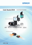
Thank you for purchasing the OMRON V400-R2 series.
This manual describes the functions, performance, and application
methods of the V400-R2 series.
This manual is intended for personnel with knowledge of electrical
systems. Be sure to read and understand this manual thoroughly before
using the product, and keep this manual in an easily accessible location
for quick reference when required.
ii
形V400-R1CF/R1CS
ユーザーズマニ ュ アル
Introduction
1 Product Overview
Section
2 Introduction Procedure
Section
3 Basic Knowledge of Operation
Section
4 Setting Method
Section
5 Appendix
Multi-code Reader
User’s Manual
V400-R2 series
Section 11 Section
Section 22 Section
Section 33 Section
Section 44 Section 5
Section
Section
Introduction
Introduc-
Introduction Terms and Conditions Agreement (Be sure to read this.)
Introduction
Introduction
Terms and Conditions Agreement
Warranty, Limitations of Liability
Terms and Conditions Agreement
Warranties
• Exclusive Warrant
Omron’s exclusive warranty is that the Products will be free from defects in materials and
workmanship for a period of twelve months from the date of sale by Omron (or such other
period expressed in writing by Omron). Omron disclaims all other warranties, express or
implied.
• Limitations
OMRON MAKES NO WARRANTY OR REPRESENTATION, EXPRESS OR IMPLIED, ABOUT
NON-INFRINGEMENT, MERCHANTABILITY OR FITNESS FOR A PARTICULAR PURPOSE
OF THE PRODUCTS. BUYER ACKNOWLEDGES THAT IT ALONE HAS DETERMINED
THAT THE PRODUCTS WILL SUITABLY MEET THE REQUIREMENTS OF THEIR
INTENDED USE.
Omron further disclaims all warranties and responsibility of any type for claims or expenses
based on infringement by the Products or otherwise of any intellectual property right.
• Buyer Remedy
OMRON MAKES NO WARRANTY OR REPRESENTATION, EXPRESS OR IMPLIED, ABOUT
Omron’s sole obligation hereunder shall be, at Omron’s election, to (i) replace (in the form
originally shipped with Buyer responsible for labor charges for removal or replacement thereof)
the non-complying Product, (ii) repair the non-complying Product, or (iii) repay or credit Buyer
an amount equal to the purchase price of the non-complying Product; provided that in no event
shall Omron be responsible for warranty, repair, indemnity or any other claims or expenses
regarding the Products unless Omron’s analysis confirms that the Products were properly
handled, stored, installed and maintained and not subject to contamination, abuse, misuse or
inappropriate modification. Return of any Products by Buyer must be approved in writing by
Omron before shipment. Omron Companies shall not be liable for the suitability or unsuitability
or the results from the use of Products in combination with any electrical or electronic
components, circuits, system assemblies or any other materials or substances or
environments. Any advice, recommendations or information given orally or in writing, are not to
be construed as an amendment or addition to the above warranty.
Omron further disclaims all warranties and responsibility of any type for claims or expenses
based on infringement by the Products or otherwise of any intellectual property right.
See http://www.omron.com/global/
or contact your Omron representative for published information.LIMITATIONS OF LIABILITY
Limitation on Liability; Etc
OMRON COMPANIES SHALL NOT BE LIABLE FOR SPECIAL, INDIRECT, INCIDENTAL, OR
CONSEQUENTIAL DAMAGES, LOSS OF PROFITS OR PRODUCTION OR COMMERCIAL
LOSS IN ANY WAY CONNECTED WITH THE PRODUCTS, WHETHER SUCH CLAIM IS
BASED IN CONTRACT, WARRANTY, NEGLIGENCE OR STRICT LIABILITY.
Further, in no event shall liability of Omron Companies exceed the individual price of the Product
on which liability is asserted.
2
V400-R2 series
User’s Manual
Introduction
Terms and Conditions Agreement
Suitability of Use
Omron Companies shall not be responsible for conformity with any standards, codes or
regulations which apply to the combination of the Product in the Buyer’s application or use of the
Product. At Buyer’s request, Omron will provide applicable third party certification documents
identifying ratings and limitations of use which apply to the Product. This information by itself is
not sufficient for a complete determination of the suitability of the Product in combination with the
end product, machine, system, or other application or use. Buyer shall be solely responsible for
determining appropriateness of the particular Product with respect to Buyer’s application, product
or system. Buyer shall take application responsibility in all cases.
NEVER USE THE PRODUCT FOR AN APPLICATION INVOLVING SERIOUS RISK TO LIFE
OR PROPERTY WITHOUT ENSURING THAT THE SYSTEM AS A WHOLE HAS BEEN
DESIGNED TO ADDRESS THE RISKS, AND THAT THE OMRON PRODUCT(S) IS PROPERLY
RATED AND INSTALLED FOR THE INTENDED USE WITHIN THE OVERALL EQUIPMENT OR
SYSTEM.
Introduction
Application Considerations
Programmable Products
Omron Companies shall not be responsible for the user’s programming of a programmable
Product, or any consequence thereof.
Disclaimers
Performance Data
Data presented in Omron Company websites, catalogs and other materials is provided as a
guide for the user in determining suitability and does not constitute a warranty. It may represent
the result of Omron’s test conditions, and the user must correlate it to actual application
requirements. Actual performance is subject to the Omron’s Warranty and Limitations of Liability.
Change in Specifications
Product specifications and accessories may be changed at any time based on improvements
and other reasons. It is our practice to change part numbers when published ratings or features
are changed, or when significant construction changes are made. However, some specifications
of the Product may be changed without any notice. When in doubt, special part numbers may be
assigned to fix or establish key specifications for your application. Please consult with your
Omron’s representative at any time to confirm actual specifications of purchased Product.
Errors and Omissions
Information presented by Omron Companies has been checked and is believed to be accurate;
however, no responsibility is assumed for clerical, typographical or proofreading errors or
omissions.
V400-R2 series
User’s Manual
3
Introduction
Introduction
Safety Precautions
Terms and Conditions Agreement
z Meanings of safety symbols
In this operation manual, precautions are indicated using the following symbols and signal words to
ensure safe use of the V400-R2 series. The precautions indicated by these symbols and signal words
are important to ensure safety and must be observed.
The symbols and signal words are as follows:
WARNING
Indicates a potentially hazardous situation which, if not avoided, will result in
minor or moderate injury, or may result in serious injury or death. Additionally
there may be significant property damage.
z Meanings of alert symbols
Indicates general prohibitions for which there is no specific symbol.
z Warning display
WARNING
This product is not designed or rated for ensuring safety of persons.
Do not use it for such purposes.
4
V400-R2 series
User’s Manual
Introduction
Introduction
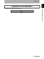
Regulations and Standards
LED safety standard
IEC 62471-1:2006 Risk exempt group
EN standard (CE mark)
EN55022/EN55024
Terms and Conditions Agreement
This product complies with the following standards.
V400-R2 series
User’s Manual
5
Introduction
Introduction
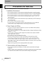
Precautions for Safe Use
Terms and Conditions Agreement
Observe the following precautions to ensure safe use of the product.
1. Installation Environment
• Do not use the product in environments containing flammable or explosive gases.
• Do not use the product in environments containing corrosive or combustible gases.
• Do not use the product in environments containing dust, salt, or metallic powders.
• Do not use the product in environments containing droplets, water or mist, oil or
chemical agents.
• Do not use the product in environments that may be affected by a CRT's flashing or
other ambient light.
• Do not install or use the product outdoors.
• For the purpose of ensuring safe operation and maintenance, do not install the
product close to high-voltage devices or electrically powered devices.
2. Power Supply and Wiring
• To assure noise and insulation resistance, be sure to use S8VS-01505 (made by
OMRON) as a driving power supply.
• Do not connect a voltage or AC power supply that has a voltage exceeding the rating
voltage (5 V+/-10%).
• Avoid reverse connection of power supply. Do not short circuit a load on OK/NG
output signal (open collector).
• Avoid applying a load that exceeds the rating.
• Be sure to turn the power OFF before connecting or disconnecting a cable.
Connecting or disconnecting a cable while the power is ON may cause failure.
• Connect different cables from high-voltage or power cables to the product. If the
same cable or duct is used, electromagnetic induction may result, which may result in
malfunction or damage.
• Tighten the fixing screws at the torque specified in this manual.
3. Communication with Upper Equipment
• Check that the product has started up, and then start communication with upper
equipment.
• Indefinite signals may be generated from the upper interface while the product starts
up. Clear the receive buffer of the devices before starting initial operation.
6
V400-R2 series
User’s Manual
Introduction
• Do not use the product in a safety circuit for nuclear or life-support systems.
• Never attempt to disassemble, repair, modify, deform by applying pressure, or burn
• Dispose of the product as industrial waste.
• If the product becomes extremely hot, or abnormal odors or smoke are emitted, stop
using the product immediately, turn the power OFF, and consult with your OMRON
representative.
V400-R2 series
User’s Manual
Terms and Conditions Agreement
the product.
Introduction
4. Other
7
Introduction
Introduction
Precautions for Correct Use
Terms and Conditions Agreement
Always observe the following precautions to prevent operation failures, malfunctions, and adverse effects
on performance and equipment.
1. Installation location
The product must not be installed in a place:
• where ambient temperature is outside the range defined in the specifications,
• where a rapid temperature change (dew condensation) occurs,
• where ambient humidity is outside the range defined in the specifications,
• where direct vibration or shock may affect the product,
• where exposed to intense ambient light (laser, arc welding, or UV light),
• where exposed to direct sunlight or heat from heating appliances, and
• where a strong magnetic or electric field exists.
Because of the protection rating described in the manual, avoid using
locations containing:
• corrosive or combustible gases,
• dust, salt, or metallic powders,
• droplets, water mist, oil or chemical agents.
2. Power supply, connection, and wiring
• Be sure to use S8VS-01505 (made by OMRON) as a driving power supply.
• Do not install the product in a location where a high-voltage device is installed.
• Be sure to user the supplied insulation board to assure the noise resistance.
• After connecting the cables, check that the correct power supply is used, that there is
no load short-circuiting or other inappropriate connections, and that the load current is
correct before turning the power ON. Faulty wiring may be the cause of failure.
• Use a wrist strap or other similar device to avoid electrostatic charge when you touch
terminals and signal lines within a connector, and to avoid damage due to static
electricity.
• Try to keep the length of the power cable to a minimum (less than 3 m).
3. Labels
• For labels with a highly gloss surface, reading errors may occur because of regular
reflection of the LED light. If this occurs, provide a skew angle of 15° against the
label.
8
V400-R2 series
User’s Manual
Introduction
• Install the product so that the front area of the reading window is free of dust and oil
droplets.
• Blow large particles off using a blower brush (for camera lenses).
Do not blow using your own breath.
• Gently wipe off small particles using a soft cloth (lens wiper) moistened with a small
amount of alcohol. Avoid vigorous wiping. Scratches on the reading window may
result in reading errors.
V400-R2 series
User’s Manual
Terms and Conditions Agreement
If dust or oil droplets are found, clean the surface using the following method.
Introduction
4. Cleaning of the reading window
9
Introduction
Introduction
How to Use This Manual
How to Use This Manual
Part names of a code
In this manual, each part of a code is described as follows.
Bar code
Label
(Paper which a bar code is printed on)
Narrow bar
(Slim lines)
Bar code
Margin
Margin
Height
Width
2D code
Label
(Paper on which a 2D code is printed on)
2D code
Cell size
Matrix size
Margin
10
V400-R2 series
User’s Manual
Introduction
Introduction
Page format
Title of each section
Preparation
Overviews and points
This section describes the setting method based on preliminary examination. Perform a test to
check whether the intended code is read and set the reading conditions for the purpose.
Testing
Section 2 Preparation
You can check how stably the intended code can be read.
Read the code at rest ten times and calculate the reading rate.
Entering the reading rate measurement mode
1. Place the code in the reading position.
2. Input the command “[XU8”.
The reader enters the reading rate measurement mode.
The reading rate in every 10 reading operations is measured.
Index label
Indicates the current section and the
title of the section.
You can quickly reach the page
containing the information you need.
How to Use This Manual
Section 2
Introduction Procedure
3. To exit the reading rate measurement mode, restart the reader.
The reader returns to the normal measurement mode.
Do not execute write command “Z2” to nonvolatile memory.
A sample setting condition is overwritten and stored, which erases the already set reading condition.
Output format
In reading rate measurement mode, the reading rate in every 10 reading operations is
output continuously to the upper equipment.
Illustration
The number of times of successful decoding (no verification)
10 reading tries
10/10
ABCDEFG
Correct reading data
Communication data format
Footer
Header
Header
Correct
Footer
reading data
Footer
V400-R2 series
User’s Manual
35
Operation procedure and additional explanation
Shows the operation procedure.
Tips and reference pages that may be useful during operation are indicated with a mark.
* This page does not actually exist.
V400-R2 series
User’s Manual
11
Introduction
Introduction
Visual Aids
Visual Aids
Indicates points that are important for using product functions or in application procedures.
Indicates page numbers providing related information.
Indicates information helpful for problem solving or explanation of technical terms.
Copyrights and Trademarks
• QR Code is a registered trademark of DENSO WAVE INCORPORATED in JAPAN and other countries.
• Other company names and product names are registered trademarks or trademarks of their respective owners.
12
V400-R2 series
User’s Manual
Introduction
Introduction
Contents
Introduction
2
Warranty, Limitations of Liability
2
Application Considerations
3
Disclaimers
3
Safety Precautions
4
Regulations and Standards
5
Precautions for Safe Use
6
Precautions for Correct Use
8
How to Use This Manual
10
Visual Aids
12
Contents
13
Section 1
Product Overview
15
Features
16
Basic Configuration
18
Part Names and Functions
19
Section 2
Introduction Procedure
Contents
Terms and Conditions Agreement
21
Introduction Flow Chart
22
Preliminary Examination
24
Wiring and Connection
31
Preparation
37
Installation and Reading
42
V400-R2 series
User’s Manual
13
Introduction
Introduction
Section 3
45
Contents
Operation Flow Chart
46
Communication Data Format
52
Code Condition Teaching Function
55
Bank Function
58
Section 4
Setting Method
59
How to Use a Menu Sheet/Command
60
Menu Sheet/Command List
62
Section 5
14
Basic Knowledge of Operation
Appendix
111
Maintenance
112
Troubleshooting
113
Specifications and External Dimension
114
ASCII Code Table
120
Quick-Reference Tables of Data Capacities
121
V400-R2 series
User’s Manual
This section explains the features, ratings, and performance of this product.
Features
16
Basic Configuration
18
Part Names and Functions
19
V400-R2 series
User’s Manual
Section 1 Product Overview
Section 1
Product Overview
15
Section 1
Product Overview
Features
This product is an ultra-compact, setup-free multi-code reader that reads most 2D and 1D
Section 1 Features
symbols on paper or labels. Various types of information can be managed efficiently by using it
with a PC and programmable controllers.
A setup-free multi-code reader that recognizes most 1D and 2D codes
printed on paper or labels
It can read various 1D and 2D codes without requiring special settings.
QR code
DataMatrix
(Automobile part)
(HDD)
Code 39
(PCB)
Code Condition Teaching Function
This function enables stable reading of specific codes by means of code condition
teaching. By combining this function with the bank selection function, you can select
and read up to 16 codes.
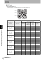
A 0.36-mega pixel CMOS image sensor
Readable barcodes and 2-dimensional barcodes are shown below.
Model
bar codes
2D codes
V400-R2CF65
0.076 mm
0.127 mm
V400-R2CF125
0.127 mm
0.212 mm
Green LED aiming function
The green LED aiming function quickly recognizes the area to be read.
16
V400-R2 series
User’s Manual
Section 1
Product Overview
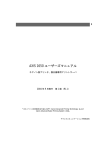
Ultra-compact body for highly flexible installation
The main body is very small, only 41.1 mm × 33 mm × 24 mm.
The front and side view types are available to suit your installation environment.
Section 1 Features
33 mm
41.1 mm
24 mm
V400-R2 series
V400-R2 series
User’s Manual
17
Section 1
Product Overview
Basic Configuration
This product is used by connecting with upper equipment such as a PC and programmable
Section 1 Basic Configuration
controllers.
The upper equipment receives the information this product reads, and records and verifies it
with the registered information.
The cable has a connector at the end. Use the appropriate connecting cable for the upper
equipment.
Multi-code reader
V400-R2 series
PC/AT compatible
Cable for connecting PC/AT compatible
V509-W011D
p.33
Power supply (5 VDC)
Dedicated product: S8VS-01505
(made by OMRON)
Programmable controller
Programmable controller made by OMRON
Connecting cable
V509-W011
18
V400-R2 series
User’s Manual
p.34
Section 1
Product Overview
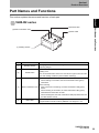
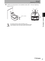
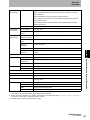
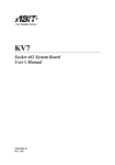
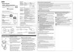
Part Names and Functions
This section explains the names and functions of each part.
Section 1 Part Names and Functions
V400-R2 series
(2) SCAN button
(3) Read confirmation LED
(4) Main cable
(1) Reading window
No.
(1)
(2)
(3)
(4)
Part name
Reading window
SCAN button
Function
Aiming light and illumination LED light is emitted from here for
capturing images.
The button for performing a reading test. Pressing it once performs
reading once.
You can hold this button down for 5 seconds or longer to save the code
type and reading conditions (code condition teaching).
When reading
When reading is successful, the read confirmation LED (green)
illuminates.
When teaching
During execution of teaching, the read confirmation LED (green)
Read confirmation LED
blinks.
When teaching is successful, the read confirmation LED (green)
illuminates and the buzzer sounds.
When teaching fails, the read confirmation LED (red) illuminates and
the BAD buzzer sounds.
Main cable
Connected to a cable for connecting PC/AT compatible or a
programmable controller made by OMRON. The length is 1.5 m.
V400-R2 series
User’s Manual
19
Section 1
Product Overview
MEMO
Section 1 Part Names and Functions
20
V400-R2 series
User’s Manual
Section 2
Introduction Procedure
product is as shown below.
Introduction Flow Chart
22
Preliminary Examination
24
Wiring and Connection
31
Preparation
37
Installation and Reading
42
V400-R2 series
User’s Manual
Section 2 Introduction Procedure
A flow chart of preliminary examination, installation, and introduction of the
21
Section 2
Introduction Procedure
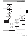
Introduction Flow Chart
A flow chart of preliminary examination, installation, and introduction of the product is as
shown below.
Section 2 Introduction Flow Chart
Preliminary
examination
Check the type, width, height, and the number of digits of 2D codes
and bar codes.
p.24 Supported code list
p.27 Reading range performance
p.29 Reading angle performance
Complete wiring.
p.31 Pin arrangement and input/output circuit
Wiring and
connection
Connect peripheral equipment.
p.33 Example of connection with a PC
p.34 Example of connection with programmable controller (CS1)
Turn on the power switch.
Press the SCAN button to check whether
the code is read.
p.37 Testing
Preparation
Investigate the reading timing.
p.38 Investigation into the reading timing
p.46 Basic operation flow chart
Set the reading condition corresponding to the purpose.
p.39 Setting the reading conditions
p.62 Menu Sheet/Command List
22
V400-R2 series
User’s Manual
Section 2
Introduction Procedure
Install the reader.
p.42 Installation
and reading
Section 2 Introduction Flow Chart
Installation
Test in the actual usage environment.
p.37 Testing
Execute reading.
In case of trouble:
I do not know the
communication specification.
I cannot understand the
operation flow.
p.52 Communication Data Format
p.46 Operation Flow Chart
V400-R2 series
User’s Manual
23
Section 2
Introduction Procedure
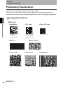
Preliminary Examination
The following are typical specifications you should consider.
Check the type, width, height, and the number of digits of 2D codes and bar codes while
considering the supported codes, reading range performance, and reading angle performance.
Section 2 Preliminary Examination
Supported code list
2D code
DataMatrix
ECC200
10 × 10 to 64 × 64
8 × 18 to 16 × 48
PDF417
Aztec Code
24
V400-R2 series
User’s Manual
QR code
Models 1 and 2
21 × 21 to 57 × 57
(Versions 1 to 10)
Micro QR code
11 × 11 to 17 × 17
Micro PDF417
Maxi Code
Codablock-F
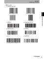
Section 2
Introduction Procedure
Bar codes
JAN/EAN and UPC
Industrial2of5(STF)
Codabar(NW-7)
CODE93
ITF
CODE128
Section 2 Preliminary Examination
CODE39
V400-R2 series
User’s Manual
25
Section 2
Introduction Procedure
GS1 DataBar (RSS)
Section 2 Preliminary Examination
GS1 DataBar Omni-directional
GS1 DataBar Truncated
GS1 DataBar Stacked
GS1 DataBar Limited
GS1 DataBar Expanded
GS1 DataBar Composite
26
V400-R2 series
User’s Manual
Section 2
Introduction Procedure
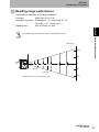
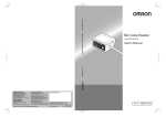
Reading range performance
Explained with examples of following conditions:
•Contrast:
MRD 63% (PCS = 0.9)
•Installation condition: Pitch angle α = 0°, skew angle β = 15°
Tilt angle γ = 0°, curvature R = ∞
•Reading rate:
90% or more in 10 tries
Section 2 Preliminary Examination
The reading range is a reference value, not a guaranteed value.
(Unit: mm)
100
50
0
50 65
100
125 150
200
250
300
50
(48, 31)
(93, 59)
(Horizontal field of view, Vertical field of view)
100
V400-R2 series
User’s Manual
27
Section 2
Introduction Procedure
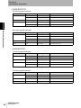
V400-R2CF125
2D code (typical example)
Code types
QR Code
Data Matrix
Section 2 Preliminary Examination
PDF417
Resolution
Reading distance
Field-of-view size at reading distance
0.212
95 to 115
70 × 44 to 85 × 54
0.381
60 to 185
44 × 28 to 137 × 87
0.254
80 to 145
59 × 38 to 107 × 68
0.169
85 to 130
63 × 40 to 96 × 61
0.254
65 to 180
48 × 30 to 133 × 85
Bar code (typical example)
Code types
Code39
Resolution
Reading distance
Field-of-view size at reading distance
0.127
90 to 125
66 × 42 to 93 × 59
0.254
70 to 190
52 × 33 to 141 × 89
0.508
65 to 235
48 × 30 to 174 × 110
Code128
0.2
80 to 160
59 × 38 to 118 × 75
UPC
0.33
55 to 185
40 × 25 to 137 × 87
V400-R2CF65
2D code (typical example)
Code types
QR Code
Resolution
Reading distance
Field-of-view size at reading distance
0.169
70 to 80
51 × 33 to 59 × 38
0.381
45 to 110
33 × 21 to 81 × 52
Data Matrix
0.212
65 to 90
48 × 31 to 66 × 42
PDF417
0.127
65 to 80
48 × 31 to 59 × 38
0.254
65 to 110
48 × 31 to 81 × 52
2D code (typical example)
Code types
Code39
28
Resolution
0.127
Reading distance
65 to 85
Field-of-view size at reading distance
48 × 31 to 62 × 40
0.254
60 to 110
44 × 28 to 81 × 52
Code128
0.18
55 to 100
40 × 26 to 74 × 47
UPC
0.33
60 to 125
44 × 28 to 92 × 58
V400-R2 series
User’s Manual
Section 2
Introduction Procedure
Reading angle performance
Pitch angle (α)
In the following conditions, readable up to α = 50° on either side.
• Code:
Resolution = 0.330 mm, UPC (12 digits), PCS = 0.9
• Reading distance:
65 mm (V400-R2CF65) or 125 mm (V400-R2CF125) from the
case end
Section 2 Preliminary Examination
• Installation condition: Skew angle β = 15°, tilt angle γ = 0°, curvature R = ∞
Skew angle (β)
In the following conditions, readable up to β = +/-50°.
• Code:
Resolution = 0.330 mm, UPC (12 digits), PCS = 0.9
• Reading distance:
65 mm (V400-R2CF65) or 125 mm (V400-R2CF125) from the
case end
• Installation condition: Pitch angle α = 0°, tilt angle γ = 0°, curvature R = ∞
Reading performance for bar codes on a highly gloss surface such as glossy paper or a card case
may be impaired because reflected illumination LED light or room illumination light enters the
reading window.
If reflected illumination LED light is the culprit, reading performance can be improved by providing
an angle of about 15° in the skew direction.
V400-R2 series
User’s Manual
29
Section 2
Introduction Procedure
Tilt angle
With this function, bar codes can be read from any angle.
Section 2 Preliminary Examination
Curvature
In the following conditions, 12-digit UPC codes can be read within a range of R
• Code:
• Reading distance:
12-digit UPC, resolution = 0.33 mm, PCS = 0.9
65 mm (V400-R2CF65) or 105 mm (V400-R2CF65) from the
case end
• Installation condition: Pitch angle α = 0°, skew angle β = 15°, tilt angle γ = 0°
30
V400-R2 series
User’s Manual
20.
Section 2
Introduction Procedure
Wiring and Connection
This section explains the pin arrangement, the input/output circuit, and the method of
connection to upper equipment.
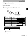
Pin arrangement and input/output circuit
Section 2 Wiring and Connection
Pin arrangement
(Pin alignment)
Connector part (DIN: 8P plug)
Made by Hosiden Corporation
TCP1394-715267 (Type A)
Connection with upper equipment p.33, p.34
Wire color Pin No. Signal name
Function
Reader
Green
1
SD
Transmission data
White
2
RD
Received data
Gray
3
RS
Transmission request
Signal direction
Upper equipment
Blue
4
CS
Transmission allowed
Brown
5
TRIG
External trigger signal
-
6
NC
Not connected
Black
7
S.GND
0V
Red
8
VCC
Power supply
External
External
Yellow
- (Note)
OK
READ OK output
External
Orange
- (Note)
NG
READ NG output
External
When you make a connection cable, use the following connectors.
Recommended parts for the connector
Usage
Manufacturer
Model
For cable relay
Hosiden Corporation
TCS8587-0170477
For panel installation
Hosiden Corporation
TCS1080-0120177
The OK and NG output lines are not connected to the DIN 8-pin connector. To use the OK and NG
outputs, cut the cables.
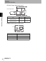
Input/output circuit
V400-R2 series
User’s Manual
31
Section 2
Introduction Procedure
External trigger signal input circuit
VCC
External trigger signal
Internal
circuit
TRIG
Section 2 Wiring and Connection
Von/off
SG
Item
Minimum value Maximum value
Terminal voltage Von when a
transistor is turned on
0V
0.8 V
Terminal voltage Voff when a
transistor is turned off
2V
5.5 V
READ OK/NG signal output circuit
OK/NG
Internal
circuit
SG
32
Item
Specification
Output system
NPN open collector
Rated load
24 VDC 30 mA
Leak current at OFF
0.5 mA or less
Residual voltage at ON
1 V or less
V400-R2 series
User’s Manual
Section 2
Introduction Procedure
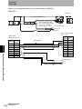
Example of connection with a PC
Example of connection with PC/AT compatible is explained.
Multi-code reader
V400-R2 series
PC/AT compatible
100 VAC
Dedicated power supply for multi-code reader
S8VS-01505 (made by OMRON)
Wiring
Upper equipment side
(Example with PC/AT compatible)
Reader side
Pin No.
Section 2 Wiring and Connection
Special cable
V509-W011D
Wire color Signal name
5
Brown
TRIG
-
Yellow
Shield
Pin No.
Signal name
1
-
OK
2
RD
SD
-
Orange
NG
3
4
Blue
CS
4
ER
3
Gray
RS
5
SG
2
White
RD
6
DR
1
Green
SD
7
CS
8
Red
VCC
8
RS
7
Black
S.GND
9
-
F.GND
Cover
Shield
Shield
5 VDC (Supplied from the
dedicated power supply)
0V
Communication with upper equipment
Check that the product has started up, and then start communication with upper equipment.
Indefinite signals may be generated from the upper interface while the product starts up. Clear the
receive buffer of the devices before starting initial operation.
V400-R2 series
User’s Manual
33
Section 2
Introduction Procedure
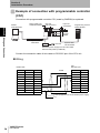
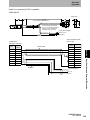
Example of connection with programmable controller
(CS1)
Connection with programmable controller CS1 (made by OMRON) is explained.
Power supply unit
C200HW-PA204S
Section 2 Wiring and Connection
Reader
V400-R2 series
CPU unit
CS1H-CPU67H
Input unit
CS1W-ID21
Programming console
C200H-PRO27
Trigger
switch
Special cable
V509-W011
100 VAC
Special cable
CS1W-CN224
Dedicated power supply for multi-code reader
S8VS-01505 (made by OMRON)
Connect the connection cable of this reader to RS-232C port of the CPU unit.
Wiring
CS1
RS-232C port
Reader side
Pin No.
Pin No.
Signal name
5
Wire color Signal name
Brown
TRIG
1
FG
-
Yellow
OK
2
SD
-
Orange
NG
3
RD
4
Blue
CS
4
RS
3
Gray
RS
5
CS
2
White
RD
6
-
1
Green
SD
7
-
8
Red
VCC
8
-
7
Black
S.GND
9
SG
Shield
Shield
F.GND
5 VDC (Supplied from the dedicated power supply)
0V
34
V400-R2 series
User’s Manual
Section 2
Introduction Procedure
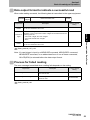
Settings on the reader
Specify the settings as follows to establish communication with the programmable
controller.
Setting item
Setting content
Command
9600 bps
(Factory default setting)
Data length
8 bits
(Factory default setting)
Parity
None
(Factory default setting)
Stop bit
1 bit
(Factory default setting)
Header
None
(Factory default setting)
Footer
CR
(Factory default setting)
Reading valid time
Trigger + 2 sec.
(Factory default setting)
Process failed reading
Transmits “NL” when no label is found
Transmits “ND” when reading has failed
TH0N0L
TI0N0D
Settings on OMRON programmable controller CS1
For information about the detailed setting method, refer to the operation manual of your
programmable controller.
Setting item
Setting content
Dip switch of CPU unit
OFF
Program controller system settings
160[830E]
Section 2 Wiring and Connection
Communication speed
161[0006]
162[0000]
164[000D]
165[0100]
DM setting
Set [1B5A] to DM00100
(Memorize “[ESC]Z” of the ASCII code)
Program controller system settings - Details
160
b15
Presence of the arbitrary
communication setting
“1”
Arbitrary setting
b11-8
Serial communication mode “11”
Nonprocedural
b3
Data length
“1”
8 bits
b2
Stop bit
“1”
1 bit
b1-0
Parity
“01”
None
161
b7-0
Communication speed
0×06
9600 bps
162
b15-0
Transmission delay time
0×0000
No delay
164
b15-8
Start code
0×00
None
b7-0
End code
0×0D
CR
b12
Presence of the start code
“0”
None
b9-8
Presence of the end code
“01”
The end code is present
165
* 0×00 means a hexadecimal number, and “0” means a binary number.
V400-R2 series
User’s Manual
35
Section 2
Introduction Procedure
Example of program
Section 2 Wiring and Connection
When the trigger switch is turned on, the reader executes the reading operation and stores the
read data to DM (data memory) of CS1.
The content is displayed on the programming console.
When the code cannot be read within the duration which is set beforehand (2 sec. in this
example), “NL” or “ND” is transmitted.
To check the read data with the programming console, press “Clear > FUN > Monitor” in this
order.
00000
00000
DIFU(13)00101
00101
00002
A39206
00006
A39205
TXD(236)
DM00100
#0000
#0002
Transmits the read command “Z” stored at
address DM00100.
BSET(71)
#0000
DM00200
DM00220
Clears the address for storage DM00200.
RXD(235)
DM00200
#0000
A393
Receives data from the reader and stores it in a
memory area starting at the address DM00200.
MSG(46)
&0
DM0200
Displays the data on the programmable console.
Communication with upper equipment
Check that the product has started up, and then start communication with upper equipment.
Indefinite signals may be generated from the upper interface while the product starts up. Clear the
receive buffer of the devices before starting initial operation.
36
V400-R2 series
User’s Manual
Section 2
Introduction Procedure
Preparation
This section describes the setting method based on preliminary examination. Perform a test to
check whether the intended code is read and set the reading conditions for the purpose.
Testing
Section 2 Preparation
You can check how stably the intended code can be read.
Read the code at rest ten times and calculate the reading rate.
Entering the reading rate measurement mode
1. Place the code in the reading position.
2. Input the command “[XU8”.
The reader enters the reading rate measurement mode.
The reading rate in every 10 reading operations is measured.
3. To exit the reading rate measurement mode, restart the reader.
The reader returns to the normal measurement mode.
Do not execute write command “Z2” to nonvolatile memory.
A sample setting condition is overwritten and stored, which erases the already set reading condition.
Output format
In reading rate measurement mode, the reading rate in every 10 reading operations is
output continuously to the upper equipment.
The number of times of successful decoding (no verification)
10 reading tries
10/10
ABCDEFG
Correct reading data
Communication data format
Footer
Header
Header
Correct
Footer
reading data
Footer
V400-R2 series
User’s Manual
37
Section 2
Introduction Procedure
Investigation into the reading timing
This reader uses the “trigger reading” system. Trigger reading uses the following trigger
input systems and reading operations.
Setting method p.76
Reading system
Trigger reading
Section 2 Preparation
Reading is executed by applying a reading trigger from outside.
Trigger input method
External trigger
signal
Reading starts when the external trigger signal is turned on. The
“Trigger controlled system” performs reading while the trigger is ON,
and the “Effective duration designation system” performs reading only
for the predetermined effective duration (*) that starts when the trigger
is ON.
RS-232C command Reading starts when the communication command is sent from the
upper equipment. After receiving the command, the reader performs
reading only for the effective duration (*) you have set beforehand.
Reading operation
Single reading
When the reading succeeds, the reader outputs the data and finishes
the reading operation.
Plural reading
The reader reads codes continuously while the trigger is ON or for the
effective duration (*). When the first reading is completed, the data is
output once. While the reader is reading the same code continuously,
it outputs no data. The reader outputs data only when the new data
differs from that of the previous code.
Continuous reading The reader reads codes continuously while the trigger is ON or for the
effective duration (*). The reader outputs data even if it reads the same
code.
*
Effective duration of reading
When the trigger input method is external trigger signal effective duration designation system or RS-232C
command, effective duration setting is required beforehand. The effective duration is set between 0 and 10
seconds.
Effective duration setting method p.79
38
V400-R2 series
User’s Manual
Section 2
Introduction Procedure
Setting the reading conditions
There are the following three setting methods for the reader. Select either method
according to the condition.
Setting method
Description
This method reads the menu sheet of the function you want to set.
This is convenient for the initial setting and when testing.
Input a command from the upper
equipment.
This method inputs a command from the upper equipment.
This is convenient when changing setup according to the type of
code.
Use the code condition teaching
function
This method lets you set reading conditions by holding down the
SCAN button on the reader for at least 5 seconds. This is convenient
when you cannot send commands from an upper equipment.
Code Condition Teaching Function p.55
Section 2 Preparation
Read the menu sheet.
Read the menu sheet.
The menu sheet is a special code used to set the reader function.
Setting can be changed by reading this menu sheet.
1. Read the menu sheet “ZZ” that starts/ends the setting procedure.
The buzzer sounds continuously, indicating that the reader has entered the setting mode.
_ZZ_
2. Read the menu sheet “U2” that restores the factory default settings.
_U2_
3. Read the menu sheet for the setting item you want to change.
Menu Sheet/Command List p.62
4. To finish, read the menu sheet “ZZ” that starts/ends the setting procedure.
The buzzer stops and the reader returns to the normal mode.
_ZZ_
V400-R2 series
User’s Manual
39
Section 2
Introduction Procedure
How to create a menu sheet
Menu sheets use the CODE39 code system. However, the code used for this reader is
special as a space mark is used as the start and stop codes. (Normally “*”)
You can create a menu sheet using readily available code creation software, as shown
below.
Section 2 Preparation
40
E.g.: When creating a menu sheet “A3”
Create “* A3 *” and cut the parts of “*” with scissors to create the menu sheet “A3”.
*_A3_*
Cutting off section
V400-R2 series
User’s Manual
Cutting off section
Section 2
Introduction Procedure
Inputting a command from the upper equipment
Multi-code reader
V400-R2 series
Upper equipment
Transmits command character strings
Section 2 Preparation
1. Transmit the command character strings of the function you want to set.
Command
Menu Sheet/Command List p.62
2. Transmit the command “Z2” to write the setting data in the nonvolatile memory of the
reader.
Be sure to write the setting data in the nonvolatile memory whenever a condition is set by inputting a
command from the upper equipment. When you turn the power OFF without writing the setting in the
memory, the settings will be lost.
Transmission method of the command by designating values and characters is
explained as follows.
E.g.: Setting “AB” on header (Designating codes directly)
Header setting
command
Character
“A”
Character
“B”
V400-R2 series
User’s Manual
41
Section 2
Introduction Procedure
Installation and Reading
This section explains how to install the reader and conduct a final check to confirm that the
reader works successfully in the actual environment.
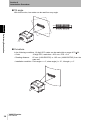
Installation
Section 2 Installation and Reading
Installing the reader
Install the reader at a distance where it captures the code correctly.
Field of view and distance in relation to the code
For information about the installation distance and code resolution, refer to “Reading range
performance” on p.27.
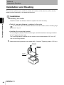
Installing the mounting bracket
To avoid regular reflection of illumination light, install the bracket at an angle of about
15 to 30 against the bar code.
The mounting bracket supplied with the reader can be tilted between -30° and +30°.
Use this mounting bracket.
1. Attach the mounting bracket to the reader (M2 × 6 screws, Tightening torque: 0.15 N·m).
M2×6 screw
M2×6 screw
Mounting
bracket
42
V400-R2 series
User’s Manual
Section 2
Introduction Procedure
2. Install the mounting bracket to the installation location (M5 × 10 screw, Tightening
torque: 2.3 N·m)
30°
30°
Section 2 Installation and Reading
M5 × 10 screw
• Do not apply stress to the cable when installing or using.
• The reading distance and angle ranges may differ depending on labels.
Before installing the reader, check that the label is read successfully.
V400-R2 series
User’s Manual
43
Section 2
Introduction Procedure
MEMO
Section 2 Installation and Reading
44
V400-R2 series
User’s Manual
Section 3
Basic Knowledge of Operation
This section explains main functions of the reader.
46
Communication Data Format
52
Code Condition Teaching Function
55
Bank Function
58
V400-R2 series
User’s Manual
Section 3 Basic Knowledge of Operation
Operation Flow Chart
45
Section 3
Basic Knowledge of Operation
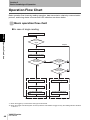
Operation Flow Chart
Basic operation flow charts by reading operation, data transmission charts by communication
protocol, and timing charts of buzzer and LED indication are shown below.
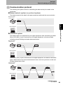
Basic operation flow chart
In case of single reading
Section 3 Operation Flow Chart
Power on
Wait for the reading
trigger
Repeat
Illumination light on
Reading process execution
Has reading
succeeded?
Is the external
trigger finished?
(*1)
Has reading effective
duration passed?
(*2)
Illumination light off
Illumination light off
READ OK LED illuminates
Reading data output
Process when reading failed
Repeat
Process when reading succeeded
Process when reading failed
*1: When the trigger by a command is used, ignore this clause.
*2: When the trigger controlled system is used (codes are read while the trigger is ON), the reading effective duration
is set to 0.
46
V400-R2 series
User’s Manual
Section 3
Basic Knowledge of Operation
In case of plural reading
Power on
Wait for the reading
trigger
Repeat
Illumination light on
Has reading
succeeded?
Is the external
trigger finished?
(*1)
Is the data different from
the previous reading?
Has reading effective
duration passed?
(*2)
Is the external
trigger finished?
(*1)
READ OK LED illuminates
Section 3 Operation Flow Chart
Reading process execution
Illumination light off
Reading data output
Has reading effective
duration passed?
Process when reading
is OK
Process when reading failed
No label in the front?
Process when reading is NG
Illumination light off
Has the reset time
passed?
Previous reading data is reset
*1: When the trigger by a command is used, ignore this clause.
*2: When the trigger controlled system is used (codes are read while the trigger is ON), the reading effective duration
is set to 0.
V400-R2 series
User’s Manual
47
Section 3
Basic Knowledge of Operation
In case of continuous reading
Power on
Wait for the reading
trigger
Repeat
Repeat
Illumination light on
Section 3 Operation Flow Chart
Reading process execution
Has reading
succeeded?
Is the external
trigger finished?
(*1)
READ OK LED illuminates
Has reading effective
duration passed?
(*2)
Reading data output
Process when reading is OK
Illumination light off
Process when reading failed
Process when reading is NG
*1: When the trigger by a command is used, ignore this clause.
*2: When the trigger controlled system is used (codes are read while the trigger is ON), the reading effective duration
is set to 0.
48
V400-R2 series
User’s Manual
Section 3
Basic Knowledge of Operation
Communication protocol
The following two systems exist for transmitting the data read by the reader to the
equipment.
Nonprocedural system (no protocol system)
The reader transmits the data to the upper equipment and ends the communication.
Multi-code reader
V400-R2 series
Data
End
ACK/NAK system
The reader waits for a response from the upper equipment after transmitting the data.
When ACK (06H) 1 byte is received from the upper equipment, a buzzer sounds
indicating normal finishing and ends data transmission.
Multi-code reader
V400-R2 series
Data
Section 3 Operation Flow Chart
Upper equipment
End
Upper equipment
When NAK (15H) 1 byte is received from the upper equipment, the data is transmitted
again. When the time-up time set beforehand comes, the time-up buzzer sounds and
the data transmission ends.
Multi-code reader
V400-R2 series
Data
Data
Data
Upper equipment
V400-R2 series
User’s Manual
49
Section 3
Basic Knowledge of Operation
Communication timing chart
This section explains the timing of the buzzer and LED indication.
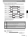
In case of reading OK (single reading)
In cases when READ OK signal output is set for One-shot system.
Trigger input
T6
T0
Illumination
light on
Section 3 Operation Flow Chart
Reading
operation
READ
OK signal
T2
T3
LED
T4
Communication
T5
Time
Description
T0
Trigger ON time. Keep the external trigger ON for at least 50 ms.
The reading time depends on the “trigger effective duration” setting.
T2
Reading valid time. (The factory default setting is 2 sec. It can be changed.) In case of reading
OK, the illumination LED turns off and the reading operation finishes as soon as the operation
succeeds.
T3
One-shot duration. It depends on the setting for “One-shot duration”. (In case when READ OK
signal output is set for One-shot system.)
T4
Buzzer and indication LED illumination time. (The factory default settings are 50 ms for the
buzzer and 200 ms for the indication LED. They can be changed.)
T5
Communication time. This differs depending on communication conditions.
T6
Trigger signal minimum OFF time. Be sure to set 5 ms or more.
• In case of continuous reading and plural reading, illumination light is emitted throughout the reading
effective duration that starts when a trigger is input. The concept of T0 to T4 is the same as that in
the case of single reading.
• Concept of communication time
Communication =
time (ms)
50
V400-R2 series
User’s Manual
(Data length) + (In case when parity exists) + (Number of stop bits)
(Communication speed)
x (Number of digits of
communication data + Number of
header characters + Number of
footer characters) x 103
Section 3
Basic Knowledge of Operation
In case of reading NG (single reading)
In case when READ OK signal output is set for trigger signal synchronous system.
The READ NG signal is output when any code other than the labels registered in
“Setting for label registration” (p.89) is read.
Trigger input
T5
T0
T0
Illumination
light on
Section 3 Operation Flow Chart
Reading
operation
T2
T2
READ
NG signal (*)
LED
Communication
T3
T3
T4
T4
*The READ NG signal is output when any code other than the labels registered in
“Setting for label registration” (p.89) is read.
Register labels to output READ NG signal.
Setting for label registration p.89
Time
Description
T0
Trigger ON time. Keep the external trigger ON for at least 50 ms.
Here, it is assumed that the reading time is “trigger controlled”.
T2
Reading valid time. (The factory default setting is 2 sec. It can be changed.)
In case of “trigger controlled” and reading NG, the illumination LED turns off and the reading
operation finishes as soon as the external trigger turns off.
T3
When the error message output is set to ON, this is the indication LED illumination time.
T4
This is the error message transmission time when the error message output is set to ON. This
differs depending on communication conditions.
T5
Trigger signal minimum OFF time. Be sure to set 5ms or more.
• In case of continuous reading and plural reading, illumination light is emitted throughout the reading
effective duration that starts when a trigger is input. The concept of T0 to T4 is the same as that in
the case of single reading.
• Concept of communication time
(Data length) + (In case when parity exists) + (Number of stop bits)
Communication=
time (ms)
(Communication speed)
x (Number of digits of
communication data + Number of
header characters + Number of
footer characters) x 103
V400-R2 series
User’s Manual
51
Section 3
Basic Knowledge of Operation
Communication Data Format
This section explains the format of communication between the reader and upper equipment.
Multi-code reader
V400-R2 series
Upper equipment
Input command
Reading data output
Section 3 Communication Data Format
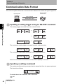
Inputting a reading trigger using an RS-232C command
The reading trigger command format is as shown below.
or
MEASURE
CR
(0DH)
or
STX
(02H)
Z
or
M
CR
(0DH)
ETX
(03H)
The continuous reading trigger command format is as shown below.
MEASURE /C
CR
(0DH)
or
M /C
CR
(0DH)
or
GC
CR
(0DH)
SC
CR
(0DH)
The continuous reading stop command format is as shown below.
MEASURE /E
CR
(0DH)
or
M /E
CR
(0DH)
or
Note: If a non-existent command is received, ER+CR(ODH) is returned.
Inputting a setting command
The reading condition setting command can be transmitted from the upper equipment.
The format is as follows.
Command
For details about the commands, refer to Section 4.
p.62
52
V400-R2 series
User’s Manual
Section 3
Basic Knowledge of Operation
Data output format to indicate a successful read
When code reading succeeds, the following data is transmitted to the upper equipment.
Header
Number
of digits
Output item
Header
Footer
Footer
Factory default
setting
Description
A character string to be added to the head of transmission characters. None
Up to four characters can be set.
The number of digits of the read data is output in ASCII code.
Whether or not to output the number of digits can be selected from the
following choices.
• “Bar code: 2 digits, 2D code: 6 digits”
• “Bar code and 2D code: 6 digits”
• None
None
A character string to be added to the end of the transmission data.
Up to four characters can be set.
CR (0DH)
Setting method p.97, p.98
Note: If a read trigger is input by a MEASURE command, MEASURE/C command,
MEASURE/E command, or an abbreviated form of one of these commands,
OK+CR(ODH) is returned before the data output format.
Process for failed reading
Section 3 Communication Data Format
Number of
digits
Data of the read code
The error message transmitted when reading fails depends on the setting.
Output item
Description
Error message - No label
This message is returned when no code exists
in the field of view.
Error message - Decoding failure
This message is returned when the code
cannot be read.
Factory default
setting
Not transmitted
Not transmitted
Setting method p.83
V400-R2 series
User’s Manual
53
Section 3
Basic Knowledge of Operation
Data transfer contents of each reading code type
Reading code
Description
Section 3 Communication Data Format
UPC-A
You can select whether or not to transfer the head character “0” for
transfer digit number adjustment and check digit C/D. (“0” is an
additional character to be combined with C/D to adjust the number of
digits to be identical to JAN/EAN-13.)
0 S X1 X2 X3 X4 X5 X6 X7 X8 X9 X10 C/D
S: Number system character (Automatically decided according to the
combination of each character of X1 to X10.)
UPC-E
You can select whether or not to transfer the head character “0” for
transfer digit number adjustment and check digit C/D. (“0” is an
additional character to be combined with C/D to adjust the number of
digits to be identical to JAN/EAN-13.)
0 S X1 X2 X3 X4 X5 X6 C/D
S: Number system character (Automatically decided according to the
combination of each character of X1 to X10.)
JAN/EAN
Reading data (8-digit or 13-digit) is transferred as it is.
ITF, Industrial2of5(STF)
Transfers in the order from the next character of the start code to the
character before the stop code. (The start code and stop code are not
transferred.)
Codabar(NW-7), CODE39
You can select whether or not to transfer the start code and stop code.
When the transfer of the start code and stop code is permitted, you can
select whether the transferred start/stop code of Codabar(NW-7) is in
lower-case “a/b/c/d” or in upper-case “A/B/C/D”.
The transfer start/stop code of CODE39 is “*”.
GS1-128
When the GS1-128 conversion is enabled, the control character “]C1”
(ASCII code: 5D, 43, 31) which indicates GS1-128 is added to the head
of the transfer data. Also, the FNC1 character, which is used as a
separating character, is replaced with the GS (ASCII code: 1DH)
character before it is transferred.
2D code
Only the reading data is transferred.
Setting method p.69
Communication with upper equipment
Check that the product has started up, and then start communication with upper equipment.
Indefinite signals may be generated from the upper interface while the product starts up. Clear the
receive buffer of the devices before starting initial operation.
54
V400-R2 series
User’s Manual
Section 3
Basic Knowledge of Operation
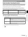
Code Condition Teaching Function
Code condition teaching is the process of saving parameters that allow you to read a specified
code type. This function is used to read a specified code only. This section explains the code
condition teaching function and the code condition teaching cancel function.
The code condition teaching function reads a code in the actual conditions of operation. If
reading is successful, the function calculates the code conditions (code type and cell size).
You can enter code condition parameters as described below.
Parameter
Description
Setting method
Set the type of code to be read.
Code condition teaching
Allow/prohibit reading command
Menu sheet
Cell size
Set the cell size of the code to be read.
For a 2D code, this is the width of one cell.
Code condition teaching
Code Condition Teaching Process
There are two methods of code condition teaching. Select the method that is best for
your circumstances.
Parameter
Description
Code condition teaching
by button
This method consists of holding down the SCAN button on the reader for at
least 5 seconds.
When code condition teaching finishes, the settings are automatically saved to
the bank whose settings were set last time or the bank that was read last time.
If a bank was not set or read, the settings are not saved to the bank data.
Code condition teaching
by command
This method consists of entering a command from an upper equipment.
When you use code condition teaching by command, the settings are not
automatically saved. After code condition teaching, execute a bank control
command to set and save the settings.
Section 3 Code Condition Teaching Function
Code type
You cannot use a menu sheet to perform code condition teaching.
V400-R2 series
User’s Manual
55
Section 3
Basic Knowledge of Operation
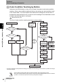
Code Condition Teaching by Button
Hold down the SCAN button on the unit for at least 5 seconds to start code condition
teaching. When code condition teaching finishes, the settings are automatically saved
to the current bank. The current bank is the bank whose settings was set last time or
the bank that was read last time.If you did not set the settings for the bank data or read
the data, the teaching result is not saved.
Bank Function p.58.
The flow of code condition teaching by button is shown below.
Section 3 Code Condition Teaching Function
SCAN button ON
Read
confirmation LED
(green) blinks 5
times
Save code conditions
from operation area
Cancel teaching
p.57
Has the reading
been succeeded?
Special teaching
measurement
Menu sheet?
Menu
processing
Teaching
successful?
Reading result
output
Read
confirmation
LED (green)
blinks
during this
time
Has the button been ON
for five seconds?
Read confirmation
LED (green)
illuminates and
buzzer sounds(*)
Read confirmation
LED (red)
illuminates and BAD
buzzer sounds
Current bank
[Set]
Restore saved
code conditions
Current bank
[Save]
Save completed
buzzer sounds
Read confirmation
LED (green/red)
OFF
End
*: The read confirmation LED operates according to the READ OK LED settings, and the buzzer operates according to
the buzzer settings.
• Code condition teaching starts after the read confirmation LED (green) blinks 5 times.
• After code condition teaching starts, place the code in the same reading position as it is in the actual
operation. The cell size may be set incorrectly if the position changes.
56
V400-R2 series
User’s Manual
Section 3
Basic Knowledge of Operation
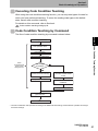
Canceling Code Condition Teaching
While using the code condition teaching function, you can only read types of codes for
which you have performed teaching. To return the reading code types to the default
state, cancel code condition teaching.
For details on this command, refer to Section 4.
Code condition teaching settings p.90.
Code Condition Teaching by Command
The flow of code condition teaching by command is shown below.
Section 3 Code Condition Teaching Function
Teaching command
Save code conditions
from operation area
Cancel teaching
Special teaching measurement
Read
confirmation LED
(green) blinks
during this time
Has teaching
succeeded?
Read confirmation LED (green)
illuminates and buzzer sounds(*)
Read confirmation LED (red)
illuminates and BAD buzzer
sounds
Response OK <CR>
Restore saved code
conditions
Response NG <CR>
Read confirmation LED
(green/red) OFF
End
*: The read confirmation LED operates according to the READ OK LED settings, and the buzzer operates according to
the buzzer settings.
V400-R2 series
User’s Manual
57
Section 3
Basic Knowledge of Operation
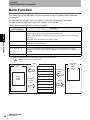
Bank Function
The reader has 16 internal banks. You can use these to save 16 types of bank parameter
information.
You can read, set, disable, check the status of, and save parameters in each bank.
You can also set a bank that is read each time the unit is started.
This section explains the bank control commands.
Command name (bank
control parameter)*
Description
Section 3 Bank Function
Read (c = 0)
This reads reading condition parameters including imaging conditions and code
conditions from the specified bank into the operation area.
When a bank parameter is disabled, the following response is returned to the upper
equipment.
## UNSET<CR> (## represents the bank number)
Set (c = 1)
This saves the reading condition parameter in the operation area to the specified bank,
and enables the bank parameter.
Disable (c = 2)
This disables the bank parameter in the specified bank.
Check Status (c = 4)
This returns the status of the bank parameter in the specified bank to the upper
equipment. When the bank parameter is disabled, 0 is returned. When enabled, 1 is
returned.
Save (c = 5)
This saves the bank parameter in the specified bank to the nonvolatile memory.
*: The bank control parameters are specified as arguments of the command.
Refer to Bank function settings (p.91).
RAM
Operation
area
Read
Bank 1
Bank 2
Bank 3
Load during
startup
Check
Status
Disable
Check Status
Disable
Set
Bank 16
58
V400-R2 series
User’s Manual
Save
Nonvolatile
memory
Bank
storage
area
Section 4
Setting Method
This section explains setting methods using a menu sheet and by entering a
command from the upper equipment.
60
Menu Sheet/Command List
62
V400-R2 series
User’s Manual
Section 4 Setting Method
How to Use a Menu Sheet/Command
59
Section 4
Setting Method
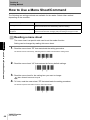
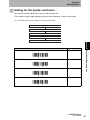
How to Use a Menu Sheet/Command
The following two setting methods are available for the reader. Select either method
depending on the condition.
Setting method
Description
Reading a menu sheet
This method reads the menu sheet of the function you want to set.
This is convenient for the initial setting and when testing.
Inputting a command from the upper
equipment
This method inputs a command from the upper equipment.
This is convenient when changing setup according to the type of code.
Reading a menu sheet
The menu sheet is a special code used to set the reader function.
Section 4 How to Use a Menu Sheet/Command
Setting can be changed by reading this menu sheet.
1. Read the menu sheet “ZZ” that starts/ends the setting procedure.
The buzzer sounds continuously, indicating that the reader has entered the setting mode.
_ZZ_
2. Read the menu sheet “U2” that restores the factory default settings.
_U2_
3. Read the menu sheet for the setting item you want to change.
Menu Sheet/Command List p.62
4. To finish, read the menu sheet “ZZ” that starts/ends the setting procedure.
The buzzer stops and the reader returns to the normal mode.
_ZZ_
60
V400-R2 series
User’s Manual
Section 4
Setting Method
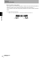
How to create a menu sheet
Menu sheets use the CODE39 code system. However, the code used for this reader is
special as a space mark is used as the start and stop codes. (Normally “*”)
You can create a menu sheet using readily available code creation software, as shown
below.
E.g.: When creating a menu sheet “A3”
Create “* A3 *” and cut the parts of “*” with scissors to create the menu sheet “A3”.
*_A3_*
Cutting off section
Cutting off section
Section 4 How to Use a Menu Sheet/Command
Inputting a command from the upper equipment
Refer to “Inputting a command from the upper equipment” (p.41).
V400-R2 series
User’s Manual
61
Section 4
Setting Method
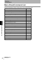
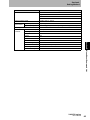
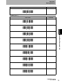
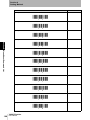
Menu Sheet/Command List
Groups are classified as follows. Please refer to the corresponding pages.
Setting item
Section 4 Menu Sheet/Command List
62
Reference
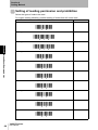
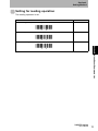
Start/end setting using menu sheets
p.63
Write setting contents on the nonvolatile memory
p.63
Setting for external trigger signal
p.63
Return to the factory default setting
p.64
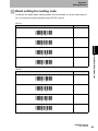
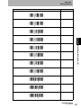
Setting of reading permission and prohibition
p.66
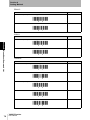
Detail setting for reading code
p.69
Setting of inverted code
p.75
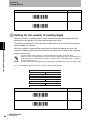
Setting for the number of times of reading coincidence
p.76
Setting for reading operation
p.77
Scan Mode Settings
p.78
Setting for reading effective duration
p.79
Setting for plural reading reset time
p.81
Setting for failed reading
p.83
Setting for the number of reading digits
p.84
Setting for the READ OK LED
p.85
Setting for the buzzer
p.85
Setting for READ OK signal output
p.87
Code condition teaching settings
p.90
Bank function settings
p.91
Setting for label registration
p.89
Setting for communication conditions
p.94
Setting for the communication protocol
p.96
Setting for the header and footer
p.97
Number of digit output
p.98
Direct code designation
p.99
V400-R2 series
User’s Manual
Section 4
Setting Method
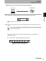
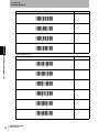
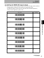
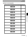
Start/end setting using menu sheets
When setting the reader using menu sheets, read this menu sheet at the start and end
of the procedure.
Menu sheet
Start/end setting using menu sheets
Command
None
_ZZ_
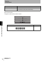
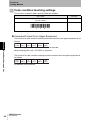
Write setting contents on the nonvolatile memory
Be sure to write the settings in the nonvolatile memory whenever a condition is set by
inputting a command from the upper equipment. When you turn the power OFF without
Section 4 Menu Sheet/Command List
writing the setting in the memory, the settings will be lost.
Menu sheet
Write the contents set with a command in the nonvolatile
memory.
Command
Z2
(No menu sheet)
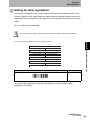
Setting for external trigger signal
Select positive logic or negative logic of the external trigger signal.
Menu sheet
External trigger signal, positive logic (H active)
Command
YA
_YA_
External trigger signal, negative logic (L active) (factory
default setting)
YB
_YB_
V400-R2 series
User’s Manual
63
Section 4
Setting Method
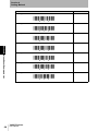
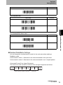
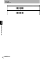
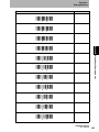
Return to the factory default setting
Menu sheet
Command
Return to the factory default setting
U2
_U2_
Factory default setting
Item
Setting content
Readable code types
JAN/UPC (A and E)/EAN(13 and 8), CODE39, Codabar(NW-7),
Industrial2of5, ITF, CODE128, CODE93, DataMatrix (ECC200), QR
code, Micro QR code, PDF417, and GS1 DataBar (RSS)
Detail
conditions
UPC-A: Transfer C/D without an 0 in the beginning
UPC/EAN detail
settings
UPC-E: Transfer C/D without an 0 in the beginning
Section 4 Menu Sheet/Command List
EAN-13: Transfer C/D
EAN-8: Transfer C/D
CODE39 detail
settings
Not calculate C/D
Transfer C/D
Not transfer ST/SP
Codebar (NW-7) detail Not calculate C/D
settings
Transfer C/D
Not transfer ST/SP
Data character of at least 5 digits
Industrial2of5(STF)
detail settings
Not calculate C/D
Transfer C/D
Code93 detail settings Transfer C/D
Reading
conditions
Bank
information
GS1-Databar(RSS)
detail settings
Transfer C/D
GS1-128(EAN128)
detail settings
Disable FNC1 to GS conversion
Reading method
(normal reading /
trigger reading)
Trigger reading
Inverted code
Black code only
Number of reading
verification times
Once
Reading operation
Single reading
Failed reading
Transmit nothing
Number of reading
digits
Not specified
Reading valid time
2 seconds
Plural reading reset
time
8 frames
Current bank
0 (Bank data not set or bank data not read)
Startup bank
0 (Do not read from any banks during startup)
Bank parameter status Disabled
LED
64
V400-R2 series
User’s Manual
READ OK LED illumination time: 200 ms
Section 4
Setting Method
Item
Buzzer
Setting content
Enable the buzzer
Single-tone buzzer
Buzzer sound duration: 50 ms
Buzzer sound volume: Max
External trigger signal
Negative logic (L active)
READ OK/NG Signal output
signal output Signal output system
External trigger synchronous system (positive logic, H active)
Label registration
None
Output signals
Communication Communication speed 9600 bps
conditions
Data length
8 bits
Parity
None
Stop bit
1 bit
Header
None
Footer
CR
Section 4 Menu Sheet/Command List
Number of digit output None
RS/CS control
None (no protocol system)
CS waiting time
Not limited
ACK/NCK waiting time Not limited
V400-R2 series
User’s Manual
65
Section 4
Setting Method
Setting of reading permission and prohibition
Select the types of code to be read.
For higher reading reliability, prohibit reading of codes that will not be read.
Menu sheet
All codes except add-ons (Factory default setting)
Command
A0
_A0_
Reading permission for all bar codes
[BCM
_BCM_
Reading permission for all 2D codes
[BCN
Section 4 Menu Sheet/Command List
_BCN_
Reading prohibition for all codes
B0
_B0_
Reading permission for UPC codes
R1
_R1_
Permission for UPC add-on 2-digit codes
R2
_R2_
Permission for UPC add-on 5-digit codes
R3
_R3_
Reading permission for JAN/EAN codes
R4
_R4_
Permission for EAN add-on 2-digit codes
R5
_R5_
Permission for EAN add-on 5-digit codes
_R6_
66
V400-R2 series
User’s Manual
R6
Section 4
Setting Method
Menu sheet
Reading permission for CODE39 codes
Command
B2
_B2_
Reading permission for Cadabar(NW-7) codes
B3
_B3_
Reading permission for Industrial2of5(STF) codes
R7
_R7_
Reading permission for ITF codes
R8
Reading permission for CODE128 codes
Section 4 Menu Sheet/Command List
_R8_
B6
_B6_
Reading permission for CODE93 codes
B5
_B5_
Reading permission for GS1 DataBar (RSS-14) codes
JX
_JX_
Reading permission for GS1 DataBar (RSS-Limited) codes
JY
_JY_
Reading permission for GS1 DataBar (RSS-Expanded) codes
DR
_DR_
Reading permission for GS1 DataBar Composite
[BHE
_BHE_
Reading permission only for DataMatrix (ECC200) codes
[BCC
_BCC_
V400-R2 series
User’s Manual
67
Section 4
Setting Method
Menu sheet
Reading permission for QR codes
Command
[BCD
_BCD_
Reading permission for Micro QR codes
[D2U
_D2U_
Reading permission for PDF417 codes
[BCF
_BCF_
Reading permission for MicroPDF417
Section 4 Menu Sheet/Command List
68
[BCG
_BCG_
Reading permission for AztecCode
[BCH
_BCH_
Reading permission for MaxiCode
[BCE
_BCE_
Reading permission for Codablock-F
_D4P_
V400-R2 series
User’s Manual
[D4P
Section 4
Setting Method
Detail setting for reading code
Conditions for details about reading codes, such as whether to use the check digit (C/
D) or to transmit the start code/stop code (ST/SP), are set.
UPC-A
Menu sheet
Transfer C/D without an 0 in the beginning (Factory default setting)
Command
E3
_E3_
Not transfer C/D without an 0 in the beginning
E5
_E5_
E2
_E2_
Not transfer C/D with 0 in the beginning
E4
_E4_
UPC-E
Menu sheet
Transfer C/D without an 0 in the beginning (Factory default setting)
Command
E7
_E7_
Not transfer C/D without an 0 in the beginning
Section 4 Menu Sheet/Command List
Transfer C/D with 0 in the beginning
E9
_E9_
Transfer C/D with 0 in the beginning
E6
_E6_
Not transfer C/D with 0 in the beginning
E8
_E8_
V400-R2 series
User’s Manual
69
Section 4
Setting Method
EAN-13
Menu sheet
Transfer C/D (Factory default setting)
Command
6K
_6K_
6J
Not transfer C/D
_6J_
EAN-8
Menu sheet
Transfer C/D (Factory default setting)
Command
6I
Section 4 Menu Sheet/Command List
_6I_
6H
Not transfer C/D
_6H_
CODE39
Menu sheet
Not calculate C/D (Factory default setting)
Command
C1
_C1_
C0
Calculate C/D
_C0_
Transfer C/D (Factory default setting)
D9
_D9_
D8
Not transfer C/D
_D8_
Transfer ST/SP
D0
_D0_
70
V400-R2 series
User’s Manual
Section 4
Setting Method
Menu sheet
Not transfer ST/SP (Factory default setting)
Command
D1
_D1_
Codabar(NW-7)
Menu sheet
Not calculate C/D (Factory default setting)
Command
H7
_H7_
Calculate C/D
H6
Transfer C/D (Factory default setting)
Section 4 Menu Sheet/Command List
_H6_
H8
_H8_
H9
Not transfer C/D
_H9_
Not transfer ST/SP (Factory default setting)
F0
_F0_
F3
ST/SP: ABCD/ABCD
_F3_
ST/SP: abcd/abcd
F4
_F4_
ST/SP: ABCD/TN*E
F1
_F1_
F2
ST/SP: abcd/tn*e
_F2_
V400-R2 series
User’s Manual
71
Section 4
Setting Method
Menu sheet
ST/SP: <DC1><DC2><DC3><DC4>/<DC1><DC2><DC3><DC4>
Command
HJ
_HJ_
HC
Data character of at least 1 digit
_HC_
Data character of at least 3 digits
HB
_HB_
Data character of at least 5 digits
HF
Section 4 Menu Sheet/Command List
_HF_
Industrial2of5(STF)
Menu sheet
Not calculate C/D (Factory default setting)
Command
G0
_G0_
Calculate C/D
G1
_G1_
Transfer C/D (Factory default setting)
E0
_E0_
Not transfer C/D
E1
_E1_
Data character of at least 1 digit
GE
_GE_
Data character of at least 3 digits
_GF_
72
V400-R2 series
User’s Manual
GF
Section 4
Setting Method
Menu sheet
Command
Data character of at least 5 digits
GI
_GI_
GS1-128(EAN-128)
Menu sheet
Command
Disable GS1 conversion (Factory default setting)
[X/0
_X/0_
Enable GS1 conversion
[X/4
GS1-Databar(RSS) Menu sheet
Menu sheet
Command
Not transfer C/D
DM
_DM_
Transfer C/D
DL
_DL_
Section 4 Menu Sheet/Command List
_X/4_
Detailed DataMatrix Settings
You can change the method used to search for the code area when reading a
DataMatrix code.
Code extraction mode 1: Searches for the code area based on the quiet zone.
Code extraction mode 2: Searches for the code area based on an L-shaped pattern.
•Command Format From Upper Equipment:
The format of a code extraction command from an upper equipment as follows.
ESC
(1BH)
[
(5BH)
D
(44H)
G
(47H)
Y
(59H)
Code extraction setting command
Q
(51H)
a
-
CR
(0DH)
Parameter
V400-R2 series
User’s Manual
73
Section 4
Setting Method
Name
Description
Code extraction setting command
[DGY
Parameter a
0: Code extraction mode 1
1: Code extraction mode 2 (factory default setting)
Menu sheet example:
Change the code extraction mode to mode 1.
Setting start (ZZ)
Code extraction setting (DGY)
Set parameter a to 0 (Q0)
Section 4 Menu Sheet/Command List
74
Setting end (ZZ)
Menu sheet
Code extraction setting
[DGY
_DGY_
V400-R2 series
User’s Manual
Command
Section 4
Setting Method
Setting of inverted code
Normally, codes are printed in black on a white background. However, some codes are
white on a black background.
Black codes on a white background are called normal (regular) codes, and white codes
in a black background are inverted codes.
Inverted codes can be read when the “Inverted code” option is selected.
Menu sheet
Normal (regular) code (Factory default setting)
Command
V2
Normal (regular) and inverted codes
Section 4 Menu Sheet/Command List
_V2_
_V2_
V4
_V4_
_V4_
V3
Inverted codes
_V3_
V400-R2 series
User’s Manual
75
Section 4
Setting Method
Setting for the number of times of reading
coincidence
When reading result coincides the number of times you have set, the reading result is
output to the RS-232C interface.
The verification system is AND verification (Continuous coincidence system). (This
cannot be changed.)
Menu sheet
Reading once and verification zero times
Command
X0
_X0_
Section 4 Menu Sheet/Command List
Reading twice and verification once (Factory default setting)
_X1_
Reading three times and verification twice
X2
_X2_
Reading four times and verification three times
X3
_X3_
Reading five times and verification four times
BS
_BS_
Reading six times and verification five times
_BT_
76
X1
V400-R2 series
User’s Manual
BT
Section 4
Setting Method
Setting for reading operation
The reading operation is set.
Menu sheet
Single reading (Factory default setting)
Command
S0
_S0_
S1
Plural reading
_S1_
Continuous reading
S2
Section 4 Menu Sheet/Command List
_S2_
V400-R2 series
User’s Manual
77
Section 4
Setting Method
Scan Mode Settings
Use these settings to set the search method (scan mode) for finding a code. If a code is
not found and reading fails, change the scan mode.
Mode 1: Standard setting.
Mode 2: Enables detailed search. The processing time may be longer compared to
scan mode 1.
Command Format From Upper Equipment:
The format of a scan mode settings command from an upper equipment is as follows.
ESC
(1BH)
[
(5BH)
D
(44H)
E
(45H)
9
(39H)
Q
(51H)
Scan mode setting command
a
-
CR
(0DH)
Parameter
Section 4 Menu Sheet/Command List
Name
Description
Scan mode setting command
[DE9
Parameter a
0: Scan mode 1 (factory default setting)
1: Scan mode 2
Menu sheet example:
Change the scan mode to scan mode 2.
Setting start (ZZ)
Scan mode setting (DE9)
Set parameter a to 1(Q1)
Setting end (ZZ)
Menu sheet
Scan mode setting
[DE9
_DE9_
78
V400-R2 series
User’s Manual
Command
Section 4
Setting Method
Setting for reading effective duration
The time during which the reading continues after a trigger is input is set. When it is set
to 0 sec., reading is controlled by the external trigger and the trigger is effective while
the external trigger is ON.
Menu sheet
0 seconds (controlled by the external trigger)
Command
Y0
_Y0_
Y1
1 second
2 seconds (Factory default setting)
Section 4 Menu Sheet/Command List
_Y1_
Y2
_Y2_
3 seconds
Y3
_Y3_
Y4
4 seconds
_Y4_
5 seconds
Y5
_Y5_
Y6
6 seconds
_Y6_
7 seconds
Y7
_Y7_
8 seconds
Y8
_Y8_
V400-R2 series
User’s Manual
79
Section 4
Setting Method
Menu sheet
9 seconds
Command
Y9
_Y9_
YM
Infinity
_YM_
Section 4 Menu Sheet/Command List
80
V400-R2 series
User’s Manual
Section 4
Setting Method
Setting for plural reading reset time
This setting has effect when plural reading is enabled.
This setting specifies the number of frames (length of time) during which the reader
should be kept away from the code before reading the same code again.
Frames
A frame is another representation of time (ms). Intervals between frames are not constant and they
differ depending on codes. When the frame is set to infinity, the next code must differ from the
previous one as long as a trigger is input.
(Example)
Frame
1
Time (ms)
50
2
3
100 200
4
5
6
7
8
300 400 500 600 700
9
10
800 900
11
1000
Command
AH
_AH_
AI
2 frames
_AI_
3 frames
AJ
_AJ_
4 frames
Section 4 Menu Sheet/Command List
Menu sheet
1 frame
AK
_AK_
AL
5 frames
_AL_
6 frames
AM
_AM_
AN
7 frames
_AN_
V400-R2 series
User’s Manual
81
Section 4
Setting Method
Menu sheet
8 frames (Factory default setting)
Command
[E9H
_E9H_
[E9I
9 frames
_E9I_
10 frames
[E9J
_E9J_
11 frames
Section 4 Menu Sheet/Command List
82
[E9K
_E9K_
AG
Infinity
_AG_
V400-R2 series
User’s Manual
Section 4
Setting Method
Setting for failed reading
Process for failed reading is set.
With the factory default setting, nothing is transmitted in the event of failed reading.
Error message - No label
Direct input characters of up to 4 digits can be set. These characters are transmitted
when no code (label) is detected during the reading time.
• The error message is disabled when no direct input characters are read after the command.
Error message - Decoding failure
when a code (label) is detected during the reading time but nothing is read.
• The error message is disabled when no direct input characters are read after the command.
E.g.: In the following two examples, the “NL<CR>” message is set for “No label” and the “ND<CR>” message
for “Decoding failure”. Those two examples may occur at the same time.
When no code is detected
during the reading time
When a code is detected during
the reading time but nothing is
read
Setting start (ZZ)
Setting start (ZZ)
Error - No label (TH)
Error - Decoding failure (TI)
N (0N)
N (0N)
L (0L)
D (0D)
<CR> (1M)
<CR> (1M)
Setting end (ZZ/Z2)
Setting end (ZZ/Z2)
Menu sheet
Error message - No label
Section 4 Menu Sheet/Command List
Direct input characters of up to 4 digits can be read. These characters are transmitted
Command
TH
_TH_
V400-R2 series
User’s Manual
83
Section 4
Setting Method
Menu sheet
Command
TI
Error message - Decoding failure
_TI_
Not transmit an error message (Factory default setting)
TG
_TG_
Setting for the number of reading digits
When the number of reading digits is fixed, all codes having other lengths than that
specified can be rejected. Up to two reading digits can be set.
Section 4 Menu Sheet/Command List
This setting is effective for codes such as Interleaved 2 of 5 for which security against
partial reading is insufficient.
While the number of reading digits to be fixed can be set by reading the code, the
number of reading digits cannot be set with a command since a code of the necessary
length must be read.
• To read codes of a known length, it is recommended that the number of digits be fixed.
• While the number of reading digits to be fixed can be set by reading the code, it is not affected by a
detail setting (p.69) for reading codes, including “Transfer ST/SP”, “Not transfer ST/SP”, “Transfer C/
D” and “Not transfer C/D”.
• Fixing the number of reading digits does not affect WPC (JAN/EAN/UPC) or other fixed-length codes.
E.g.: The following describes the steps for fixing the number of reading digits.
Setting start (ZZ)
Fixed number of digits ON (H1)
Read the first code of the necessary length
Read the second code of the necessary length
Setting end (ZZ)
Menu sheet
Fixed number of digits OFF for all codes (Factory default setting)
Command
H0
_H0_
Fixed number of digits ON for all codes
_H1_
84
V400-R2 series
User’s Manual
None
Section 4
Setting Method
Setting for the READ OK LED
The READ OK LED is disabled or its illumination time is set. The READ OK LED
illuminates when reading succeeds.
Menu sheet
Disable the READ OK LED
Command
T4
_T4_
READ OK LED illumination time: 200 ms (Factory default setting)
T5
_T5_
T6
_T6_
READ OK LED illumination time: 800 ms
T7
_T7_
Setting for the buzzer
The buzzer is enabled or disabled or its type and sound duration and volume are set.
The buzzer sounds when reading succeeds.
Menu sheet
Disable the buzzer
Section 4 Menu Sheet/Command List
READ OK LED illumination time: 400 ms
Command
W0
_W0_
Enable the buzzer (Factory default setting)
W8
_W8_
Single-tone buzzer (Factory default setting)
W1
_W1_
V400-R2 series
User’s Manual
85
Section 4
Setting Method
Menu sheet
High-low buzzer
Command
W2
_W2_
W3
High-high buzzer
_W3_
Buzzer sound duration: 50 ms (Factory default setting)
W7
_W7_
Buzzer sound duration: 100 ms
W4
Section 4 Menu Sheet/Command List
_W4_
Buzzer sound duration: 200 ms
W5
_W5_
Buzzer sound duration: 400 ms
W6
_W6_
Buzzer sound volume: Max (Factory default setting)
T0
_T0_
Buzzer sound volume: High
T1
_T1_
Buzzer sound volume: Medium
T2
_T2_
T3
Buzzer sound volume: Low
_T3_
86
V400-R2 series
User’s Manual
Section 4
Setting Method
Setting for READ OK signal output
When you want to output reading succeeded to the READ OK signal, set the conditions
of output system and duration, then set them for “signal output (X*Q)”.
The READ NG signal is output when any code other than the labels registered in
“Setting for label registration” (p.89) is read.
Menu sheet
Output the signal (Factory default setting)
Command
[X*Q
_X*Q_
Not output the signal
[X*R
Section 4 Menu Sheet/Command List
_X*R_
External trigger signal synchronous system (positive logic, H active) (Factory default [X*C
setting)
_X*C_
External trigger signal synchronous system (negative logic, L active)
[X*D
_X*D_
One-shot system (positive logic, H active)
[X*E
_X*E_
One-shot system (negative logic, L active)
[X*F
_X*F_
One-shot duration: 10 ms
[X*G
_X*G_
[X*H
One-shot duration: 20 ms
_X*H_
One-shot duration: 30 ms
[X*I
_X*I_
V400-R2 series
User’s Manual
87
Section 4
Setting Method
Menu sheet
One-shot duration: 40 ms
Command
[X*J
_X*J_
[X*K
One-shot duration: 50 ms
_X*K_
One-shot duration: 60 ms
[X*L
_X*L_
One-shot duration: 70 ms
Section 4 Menu Sheet/Command List
88
[X*M
_X*M_
[X*N
One-shot duration: 80 ms
_X*N_
One-shot duration: 90 ms
[X*O
_X*O_
One-shot duration: 100 ms
_X*P_
V400-R2 series
User’s Manual
[X*P
Section 4
Setting Method
Setting for label registration
You should first register codes in the reader so that they are recognized as OK. This
function outputs the OK signal when the reader reads a code that matches one of the
registered codes and outputs the NG signal for a code that does not match any of those
codes.
Up to 5 codes can be registered.
Up to 123 bytes of a single set of data, and up to 250 bytes of data in total can be registered.
Setting start (ZZ)
Label registration (+9)
Read the first code you want to register
Read the second code you want to register
Read the fifth code you want to register
Setting end (ZZ)
Menu sheet
Register labels
Command
Section 4 Menu Sheet/Command List
E.g.: The following describes the steps for registering labels.
+9
_+9_
To cancel a label registration, end the setting without reading a label in label
registration processing.
V400-R2 series
User’s Manual
89
Section 4
Setting Method
Code condition teaching settings
This function is used to read a specific code with stability.
Menu sheet
Start code condition teaching
Command
[DGM
(No menu sheet)
Cancel code condition teaching
[DGN
_DGN_
Command Format From Upper Equipment:
The format of a code condition teaching start command from an upper equipment is as
Section 4 Menu Sheet/Command List
90
follows.
ESC
(1BH)
[
(5BH)
D
(44H)
G
(47H)
M
(4DH)
CR
(0DH)
When teaching is successful, OK + CR (0DH) is returned.
When teaching fails, NG + CR (0DH) is returned.
The format of a code condition teaching cancel command from an upper equipment is
as follows.
ESC
(1BH)
[
(5BH)
D
(44H)
G
(47H)
A response is not returned.
V400-R2 series
User’s Manual
N
(4EH)
CR
(0DH)
Section 4
Setting Method
Bank function settings
Command Format From Upper Equipment:
The format of a bank function settings command from an upper equipment is as
follows.
ESC
(1BH)
[
(5BH)
D
(44H)
F
(46H)
C
(43H)
Q
(51H)
Bank control command
a
-
Q
(51H)
Bank No. a
Name
[DFC
Bank No. a
Bank No. nn = 10a + b
nn=01 to 16
c
-
CR
(0DH)
Bank control parameter c
0:Read
1:Set
2:Disable
3:Check Status
4:Save
•For an explanation of bank control parameters, refer to Bank Function (p.58).
•When the bank control parameter is 1 (Set), 2 (Disable), or 5 (Save), a response is not
returned.
•When the bank control parameter is 0 (Read),
a response is not returned when the bank parameter is enabled.
## UNSET + CR (0DH) (## represents the bank number) is returned when the bank
parameter is disabled.
Section 4 Menu Sheet/Command List
Bank control parameter c
Bank No. b
Q
(51H)
Description
Bank control command
Bank No. b
b
-
•When the bank control parameter is 4 (Check Status), n + CR (0DH) (n: Status, 0:
Disabled, 1: Enabled) is returned.
Menu sheet example:
Read the bank parameter of Bank No. 1.
Setting start (ZZ)
Bank control (DFC)
Set Bank No. a to 0 (Q0)
Set Bank No. b to 1 (Q1)
Set bank control parameter c to 0 (Q0)
Setting end (ZZ)
V400-R2 series
User’s Manual
91
Section 4
Setting Method
Menu sheet
Command
Bank control
[DFC
_DFC_
Check Current Bank Command
The current bank is the bank whose settings were set last time or the bank that was
read last time.
The format of a check current bank command from an upper equipment is as follows.
ESC
(1BH)
[
(5BH)
D
(44H)
G
(47H)
Q
(51H)
Section 4 Menu Sheet/Command List
•The bank number nn + CR (0DH) (nn = 01 to 16) of the bank whose settings were set
last time or the bank that was read last time is returned.
•If you did not set the settings for the bank data or read any bank data after startup, 00
+ CR (0DH) is returned.
Startup Bank Setting Command
Command Format From Upper Equipment:
The format of a startup bank setting command from an upper equipment is as follows.
ESC
(1BH)
[
(5BH)
D
(44H)
G
(47H)
R
(52H)
Startup Bank Setting Command
Name
Q
(51H)
a
-
Bank No. a
Q
(51H)
Description
[DGR
Bank No. a
Bank No. nn = 10a + b
nn=00: Do not read from any bank.
nn=01 to 16:Read from bank nn at startup.
(Default setting is nn = 00)
A response is not returned.
V400-R2 series
User’s Manual
b
-
Bank No. b
Startup bank setting command
Bank No. b
92
CR
(0DH)
CR
(0DH)
Section 4
Setting Method
Menu sheet example:
Read from bank 1 at startup.
Setting start (ZZ)
Startup bank setting (DGR)
Set Bank No. a to 0 (Q0)
Set Bank No. b to 1 (Q1)
Setting end (ZZ)
Command
[DGR
_DGR_
If the bank with the bank number set in the Bank No. parameter cannot be read, no bank data will be
loaded at startup.
Check startup bank command
Section 4 Menu Sheet/Command List
Menu sheet
Startup bank setting
The format of a check startup bank command from an upper equipment is as follows.
ESC
(1BH)
[
(5BH)
D
(44H)
G
(47H)
R
(52H)
CR
(0DH)
•The startup bank nn + CR (0DH) (nn = 01 to 16) is returned.
•If no reading of bank data is performed after startup, 00 + CR (0DH) is returned.
V400-R2 series
User’s Manual
93
Section 4
Setting Method
Setting for communication conditions
The settings made here are not fixed until the menu sheet “ZZ” for ending setting is
read or the setting save command “Z2” is transmitted and the reader is restarted.
Menu sheet
Communication speed: 300 bps
Command
K1
_K1_
Communication speed: 600 bps
K2
_K2_
Section 4 Menu Sheet/Command List
Communication speed: 1200 bps
K3
_K3_
Communication speed: 2400 bps
K4
_K4_
Communication speed: 4800 bps
K5
_K5_
Communication speed: 9600 bps (Factory default setting)
K6
_K6_
Communication speed: 19200 bps
K7
_K7_
Communication speed: 38400 bps
K8
_K8_
Communication speed: 57600 bps
K9
_K9_
Communication speed: 115200 bps
_SZ_
94
V400-R2 series
User’s Manual
SZ
Section 4
Setting Method
Menu sheet
Data length: 7 bits
Command
L0
_L0_
Data length: 8 bits (Factory default setting)
L1
_L1_
Parity: None (Factory default setting)
L2
_L2_
Parity: Even number
L3
Section 4 Menu Sheet/Command List
_L3_
L4
Parity: Odd number
_L4_
Stop bit: 1 bit (Factory default setting)
L5
_L5_
L6
Stop bit: 2 bits
_L6_
V400-R2 series
User’s Manual
95
Section 4
Setting Method
Setting for the communication protocol
Menu sheet
Communication protocol: No protocol system (Factory default setting)
Command
P0
_P0_
Communication protocol: With RS/CS control (Ready/Busy system)
P1
_P1_
Communication protocol: ACK/NAK system
Section 4 Menu Sheet/Command List
_P3_
CS waiting time: Not limited (Factory default setting)
I0
_I0_
I1
CS waiting time: 100 ms
_I1_
CS waiting time: 200 ms
I2
_I2_
I3
CS waiting time: 400 ms
_I3_
96
P3
V400-R2 series
User’s Manual
Section 4
Setting Method
Setting for the header and footer
Direct input header and footer of up to 4 digits can be set.
The number of digit output setting (p.98) can be included as 1 digit in the header.
E.g.: The following describes the steps for setting the header (AB).
Setting start (ZZ)
Set the headers collectively (RY)
Set “A” (0A)
Set “B” (0B)
Setting end (ZZ)
Command
RY
_RY_
Clear the header (Applied to all codes)
MG
_MG_
Set the footers collectively (Applied to all codes)
RZ
_RZ_
Clear the footer (Applied to all codes)
Section 4 Menu Sheet/Command List
Menu sheet
Set the headers collectively (Applied to all codes)
PR
_PR_
V400-R2 series
User’s Manual
97
Section 4
Setting Method
Number of digit output
Whether to output the number of digits to the data output format is specified.
This setting item can be registered as 1 item of the header and is added to a location
determined by the order of registration.
Two-byte characters are handled as 2 characters in 2D codes.
Set “Clear the header (MG)” to clear the number of digit output.
E.g.: The following describes the steps for setting the number of digit output.
Setting start (ZZ)
Set the headers collectively (RY)
Output the number of digits ($3)
Section 4 Menu Sheet/Command List
Setting end (ZZ)
Menu sheet
Number of digit output
(Bar code: 2 digits, 2D code: 6 digits)
Command
$3
_$3_
Number of digit output
(Bar code and 2D code: 6 digits)
$6
_$6_
The output format is as shown below.
• When the the number of digits output is set to [ZZRY$3ZZ] (barcode 2 digits), the number of digits is
"05" when the data of the barcode of the scanned code is "ABCDE".
• When the number of digits output is set to [ZZRY$6ZZ] (barcode 6 digits), the number of digits is
"000005" when the data of the barcode of the scanned code is "ABCDE".
98
V400-R2 series
User’s Manual
Section 4
Setting Method
Direct code designation
Used to set character strings and values directly when designating the header or footer.
Menu sheet
<SPACE>
Command
5A
_5A_
!
5B
_5B_
5C
"
#
Section 4 Menu Sheet/Command List
_5C_
5D
_5D_
$
5E
_5E_
5F
%
_5F_
&
5G
_5G_
5H
'
_5H_
(
5I
_5I_
)
5J
_5J_
V400-R2 series
User’s Manual
99
Section 4
Setting Method
Menu sheet
*
Command
5K
_5K_
5L
+
_5L_
,
5M
_5M_
-
5N
Section 4 Menu Sheet/Command List
_5N_
5O
.
_5O_
/
5P
_5P_
6A
:
_6A_
;
6B
_6B_
<
6C
_6C_
6D
=
_6D_
>
6E
_6E_
100
V400-R2 series
User’s Manual
Section 4
Setting Method
Menu sheet
?
Command
6F
_6F_
6G
@
_6G_
[
7A
_7A_
\
7B
Section 4 Menu Sheet/Command List
_7B_
7C
]
_7C_
^
7D
_7D_
7E
_
_7E_
`
7F
_7F_
{
9T
_9T_
9U
|
_9U_
}
9V
_9V_
V400-R2 series
User’s Manual
101
Section 4
Setting Method
Menu sheet
~
Command
9W
_9W_
Q0
0
_Q0_
1
Q1
_Q1_
2
Q2
Section 4 Menu Sheet/Command List
_Q2_
Q3
3
_Q3_
4
Q4
_Q4_
Q5
5
_Q5_
6
Q6
_Q6_
7
Q7
_Q7_
Q8
8
_Q8_
9
Q9
_Q9_
102
V400-R2 series
User’s Manual
Section 4
Setting Method
Menu sheet
A
Command
0A
_0A_
0B
B
_0B_
C
0C
_0C_
D
0D
Section 4 Menu Sheet/Command List
_0D_
0E
E
_0E_
F
0F
_0F_
0G
G
_0G_
H
0H
_0H_
I
0I
_0I_
0J
J
_0J_
K
0K
_0K_
V400-R2 series
User’s Manual
103
Section 4
Setting Method
Menu sheet
L
Command
0L
_0L_
0M
M
_0M_
N
0N
_0N_
O
0O
Section 4 Menu Sheet/Command List
_0O_
0P
P
_0P_
Q
0Q
_0Q_
0R
R
_0R_
S
0S
_0S_
T
0T
_0T_
0U
U
_0U_
V
0V
_0V_
104
V400-R2 series
User’s Manual
Section 4
Setting Method
Menu sheet
W
Command
0W
_0W_
0X
X
_0X_
Y
0Y
_0Y_
Z
0Z
Section 4 Menu Sheet/Command List
_0Z_
$A
a
_$A_
b
$B
_$B_
$C
c
_$C_
d
$D
_$D_
e
$E
_$E_
$F
f
_$F_
g
$G
_$G_
V400-R2 series
User’s Manual
105
Section 4
Setting Method
Menu sheet
h
Command
$H
_$H_
$I
i
_$I_
j
$J
_$J_
k
$K
Section 4 Menu Sheet/Command List
_$K_
$L
l
_$L_
m
$M
_$M_
$N
n
_$N_
o
$O
_$O_
p
$P
_$P_
$Q
q
_$Q_
r
$R
_$R_
106
V400-R2 series
User’s Manual
Section 4
Setting Method
Menu sheet
s
Command
$S
_$S_
$T
t
_$T_
u
$U
_$U_
v
$V
Section 4 Menu Sheet/Command List
_$V_
$W
w
_$W_
x
$X
_$X_
$Y
y
_$Y_
z
$Z
_$Z_
(NULL)
9G
_9G_
1A
(SOH)
_1A_
(STX)
1B
_1B_
V400-R2 series
User’s Manual
107
Section 4
Setting Method
Menu sheet
(ETX)
Command
1C
_1C_
1D
(EOT)
_1D_
(ENQ)
1E
_1E_
(ACK)
1F
Section 4 Menu Sheet/Command List
_1F_
1G
(BEL)
_1G_
(BS)
1H
_1H_
1I
(HT)
_1I_
(LF)
1J
_1J_
(VT)
1K
_1K_
1L
(FF)
_1L_
(CR)
1M
_1M_
108
V400-R2 series
User’s Manual
Section 4
Setting Method
Menu sheet
(SO)
Command
1N
_1N_
1O
(SI)
_1O_
(DLE)
1P
_1P_
(DC1)
1Q
Section 4 Menu Sheet/Command List
_1Q_
1R
(DC2)
_1R_
(DC3)
1S
_1S_
1T
(DC4)
_1T_
(NAK)
1U
_1U_
(SYN)
1V
_1V_
1W
(ETB)
_1W_
(CAN)
1X
_1X_
V400-R2 series
User’s Manual
109
Section 4
Setting Method
Menu sheet
(EM)
Command
1Y
_1Y_
1Z
(SUB)
_1Z_
(ESC)
9A
_9A_
(FS)
9B
Section 4 Menu Sheet/Command List
_9B_
9C
(GS)
_9C_
(RS)
9D
_9D_
9E
(US)
_9E_
DELL
9F
_9F_
110
V400-R2 series
User’s Manual
Section 5
Appendix
112
Troubleshooting
113
Specifications and External Dimension
114
ASCII Code Table
120
Quick-Reference Tables of Data Capacities
121
V400-R2 series
User’s Manual
Section 5 Appendix
Maintenance
111
Section 5
Appendix
Maintenance
Directions on the handling of the reader
The reading window contains precision optics. Care should be taken when handling the
reader.
Dust, dirt or cracks should degrade image capture conditions, rendering data
unreadable.
• Do not touch the lens with hands or any sharp object.
• Use the reader in a dust- and dirt-free environment. If the lens becomes contaminated, clean it with
a lens cleaning cloth or an airbrush.
Inspection
To use the reader in a good working condition, do the following:
• If the lens becomes contaminated with dust or dirt, remove it with a lens cleaning cloth or an airbrush.
• For dust or dirt on other surfaces, gently wipe off with a soft cloth.
Section 5 Maintenance
112
Item to be
inspected
Description
Tool required
Power supply
Should be within the rating voltage (5 V +/-10%) when the voltage
is measured on the power supply terminal block.
Voltmeter
Operating
temperature limit
Should be within a range of 0 to 45°C when the interior
temperature is measured.
Thermometer
Operating
humidity limit
Should be within a range of 35 to 85% when the interior
temperature is measured.
Hygrometer
Condition of the
reader installed
The reader and its mounting bracket must be properly secured.
Torque driver
V400-R2 series
User’s Manual
Section 5
Appendix
Troubleshooting
Connection
Symptom
Buzzer does not sound when
power is supplied
Cause
Refer to:
• The power supply is not properly connected.
p.33
p.114
• Not enough power capacity/current capacity.
Reading operation
Symptom
Unable to read
Cause
Refer to:
• Reading prohibition is set for the relevant code.
• The minimum resolution, reading distance and contrast
p.66
p.29, p.114
are not within the effective range.
External input/output signals (TRIG, OK, NG)
Symptom
Fails to respond to signal from
TRIG
Cause
Refer to:
p.31
OK and NG signals are not output • The signal line is not properly connected.
p.31
RS-232C
Symptom
Communication failure
Cause
Refer to:
• The communication cable is not properly connected.
p.33
• Communication specifications do not conform to upper
p.52
equipment.
• Correct communication protocol is not selected.
p.49, p.96
V400-R2 series
User’s Manual
Section 5 Troubleshooting
• The signal line is not properly connected.
113
Section 5
Appendix
Specifications and External Dimension
Specifications
General specification
Model
V400-R2CF65
Direction of view
Front view
Applicable
codes(*1)
Reading
performance
(*2)
Section 5 Specifications and External Dimension
Interface
V400-R2CF125
Bar code
WPC(JAN/EAN/UPC), Codabar(NW-7), ITF,Industrial2of5(STF), Code39,
Code93, Code128, GS1-128(EAN-128), GS1-Databar(RSS-14),
GS1-Databar Limited(RSS Limited), GS1-Databar Expanded(RSS
Expanded), GS1-Databar Composite(RSS Composite)
2D code
QR code, DataMatrix(ECC200), MicroQR code, PDF417, MicroPDF417,
AztecCode, MaxiCode, Codablock-F
Number of reading
digits
No upper limit (depends on bar width and reading distance)
Light source
Two red LEDs (wave length: 617 nm)
Aiming light
One green LED (wave length: 528 nm)
Minimum
resolution
Bar code: 0.076 mm
2D code: 0.127 mm
Image capture
device
Monochrome CMOS
Effective number
of pixels
754 × 480 pixels
Working distance
(WD)
65 mm
125 mm
Field of view
Approximately 48 × 31
(for WD = 65 mm)
Approximately 93 × 59
(for WD = 125 mm)
Pitch angle (α)
±50°
Screw angle (β)
±50°
Tilt angle (γ)
±180°
Reading of bar
codes on curved
surfaces (R)
R 20mm (UPC 12 line)
Communication
specification
RS-232C
OK/NG outputs
NPN open collector output (cable work required)
Bar code: 0.127 mm
2D code: 0.212 mm
Function setting method
Menu sheet reading, Sending commands from upper equipment, or SCAN
button (only when executing code condition teaching)
Functional
specifications
Reading trigger
External trigger (Transistor input)
Trigger by command (RS-232C)
Trigger a test reading by pressing the SCAN button on the product
OK/NG signals
• When the label is not registered
OK signal: ON when reading is successful
NG signal: Not used
• When the label is registered
OK signal: ON when reading result matches registered label
NG signal: ON when reading result does not match registered label
114
V400-R2 series
User’s Manual
Section 5
Appendix
Functional
specifications
Indication LED
• When reading
Read confirmation LED (green) illuminates when reading is successful.
• When teaching
Read confirmation LED (green) blinks during execution.
When teaching is successful, read confirmation LED (green) illuminates
and buzzer sounds.
When teaching fails, read confirmation LED (red) illuminates and BAD
buzzer sounds.(*3)
Notifies a successful reading with a buzzer sound (Muting available)
Power supply
specification
Power voltage
4.5 to 5.5 VDC
Consumption
current
During operation: 265 mA or less; during standby: 70 mA or less
Environmental
specifications
Ambient
temperature range
At operation: 0 to + 45°C; At storage: -10 to + 60°C
Ambient humidity
range
At operation and storage: 20 to 85% RH (with no icing or condensation)
Ambient
atmosphere
No corrosive gases
Ambient light
Fluorescent lamp: 10,000lx or less, Sunlight: 100,000lx or less
Vibration
resistance
10 to 150 Hz, half amplitude 0.35 mm, 3 directions (X/Y/Z), 8 minutes each
10 times
Degree of protection
Weight
Dimensions
IP65 (IEC60529)
Main unit only
Approximately 90 g
Including
accessories
Approximately 200 g (including mounting bracket and screws)
Packaged weight
Approximately 280 g (including packing carton)
Main unit
Approximately 41(W) × 33(D) × 24(H) mm
Packing carton
Approximately 240(W) × 110(D) × 40(H) mm
Input/output connector
Round DIN connector
Code length
Approximately 1.5 m
Minimum bending radius of cord
Approximately 23 mm
Accessories
Operation manual, menu sheet, mounting bracket, M2 × 6 screws (two), M5 ×
10 screws (two)
Material, Color
Case
PC, PET, black
Reading window
PMMA, transparent
Cable
Polyvinyl chloride (PVC), black
Mounting bracket
SUS304, silver
Section 5 Specifications and External Dimension
Buzzer
*1: These are the code types supported based on Omron’s read capability validation standard. It is recommended that
the customer do its own validation in its actual work environment.
*2: Unless otherwise specified, the reading performance is defined with angle α = 0°, β = +15°, r = 0°, R = ∞;
illuminance: 100 to 2001x, reading rate: 90% or more.
*3: The BAD buzzer is two low-pitched buzz sounds.
V400-R2 series
User’s Manual
115
Section 5
Appendix
External Dimension
Multi-code Reader
V400-R2CF65/R2CF125
(Unit: mm)
2-M2 Depth 3 max
Light axis
10.65
24
18.4
2-M2 Depth 3 max
18
22
33
41.1
35.1
1.25
20
Section 5 Specifications and External Dimension
10.65
Light axis
Vinyl insulated round cord
Standard length 1.5 m
16
37
3.8 10-core Black
Connector
30°
30°
47
R1
1.25
.6
2-R2
12
12
25
10.65
3
26.45
Light axis
2-M5
15°
13
15°
.1
R35
R
21
1.
8.9
Mounting hole dimensions
116
V400-R2 series
User’s Manual
Section 5
Appendix
Mounting bracket
(Unit: mm)
R15.6
R10
.4
60°
10
2-R
30
2.6
5.2
12
2
2-R
47
2.2
38.1
Sensor fastening screws: M2x5 set screws x2
Wall mount screws: M5x8 set screws x2
28
30°
R34
R36.2
Section 5 Specifications and External Dimension
1.1
2-R
2
R
2-
V400-R2 series
User’s Manual
117
Section 5
Appendix
Cable for programmable controller connection made by OMRON
V509-W011
(Unit: mm)
Vinyl insulated round cord φ5.1
Vinyl insulated round cable,
D-sub 9 pin
φ3.8, 3-core (conductor section
area: 0.2 mm2, diameter of
insulation body: φ1.0 mm)
Pink (external trigger)
Brown (+5 V)
Blue (0 V)
Upper equipment side
D-sub 9 pin
Reader side
DIN 8-pin connector
Section 5 Specifications and External Dimension
118
No.
Signal
name
1
Shield cable
Signal
name
No.
FG
1
SD
2
SD
RD
3
2
RD
RS
4
3
RS
CS
5
4
CS
-
6
5
TRIG
-
7
6
-
-
8
7
SG
SG
9
8
+5 V
(External trigger)
(+5 V)
(0 V)
V400-R2 series
User’s Manual
Section 5
Appendix
Cable for connecting PC/AT compatible
V509-W011D
(Unit: mm)
Vinyl insulated round cord φ5.1
Vinyl insulated round cable,
φ4.7, 3-core (conductor section
area: 0.2 mm2, diameter of
insulation body: φ1.0mm)
D-sub 9 pin
Pink (external trigger)
Brown (+5 V)
Blue (0 V)
Upper equipment side
D-sub 9 pin
Reader side
DIN 8-pin connector
Signal
name
No.
-
1
1
SD
RD
2
2
RD
SD
3
3
RS
ER
4
4
CS
SG
5
5
TRIG
DR
6
6
-
RS
7
7
SG
CS
8
8
+5 V
-
9
Shield cable
Shield wire Connector Cover
Shielded
(External trigger)
(+5 V)
(0 V)
V400-R2 series
User’s Manual
Section 5 Specifications and External Dimension
No.
Signal
name
119
Section 5
Appendix
ASCII Code Table
Data read via RS-232C communications is output in ASCII code.
The table below shows one-to-one correspondence between each character and the ASCII
code used.
Examples:
•For read data “A”: Hexadecimal “41” is output.
•For read data “T”: Hexadecimal “54” is output.
Upper 4 bits
Lower 4 bits
Section 5 ASCII Code Table
120
V400-R2 series
User’s Manual
Section 5
Appendix
Quick-Reference Tables of Data Capacities
The maximum amount of data that can be stored in a code varies with the symbol size. The
character types, order and combinations of different characters also affects the data capacity.
The relation between symbol size (number of cells) and data capacity is shown in the table
below.
DataMatrix
DataMatrix ECC200
In this example, the symbol size is 12 × 12 cells.
12 cells
Maximum data capacity
Symbol size
Numbers
Alphanumeric
characters
Symbols
Kanji
(two bytes)
Kana
(one byte)
10 × 10
6
3
3
-
1
12 × 12
10
6
5
1
3
14 × 14
16
10
9
3
6
16 × 16
24
16
14
5
10
18 × 18
36
25
22
8
16
20 × 20
44
31
28
10
20
22 × 22
60
43
38
14
28
24 × 24
72
52
46
17
34
26 × 26
88
64
57
21
42
32 × 32
124
91
81
30
60
36 × 36
172
127
113
42
84
40 × 40
228
169
150
56
112
44 × 44
288
214
190
72
142
48 × 48
348
259
230
86
172
52 × 52
408
304
270
101
202
64 × 64
560
418
372
139
278
8 × 18
10
6
5
1
3
8 × 32
20
13
12
4
8
12 × 26
32
22
20
7
14
12 × 36
44
31
28
10
20
16 × 36
64
46
41
15
30
16 × 48
98
72
64
23
47
V400-R2 series
User’s Manual
Section 5 Quick-Reference Tables of Data Capacities
12 cells
121
Section 5
Appendix
QR Code
QR Code Model 2
In this example, the symbol size is 21 x 21 cells (version 1).
7 cells
7 cells
7 cells
7 cells
14 cells
Maximum data capacity
Symbol size
(version)
Section 5 Quick-Reference Tables of Data Capacities
21 × 21
(version 1)
25 × 25
(version 2)
29 × 29
(version 3)
33 × 33
(version 4)
37 × 37
(version 5)
41 × 41
(version 6)
122
V400-R2 series
User’s Manual
Error correction level
(ECC level)
Numbers
Alphanumeric
characters
(upper case
only)
L (7%)
41
25
17
10
M (15%)
34
20
14
8
8 bits
(byte)
Kanji
Q (25%)
27
16
11
7
H (30%)
17
10
7
4
L (7%)
77
47
32
20
M (15%)
63
38
26
16
Q (25%)
48
29
20
12
H (30%)
34
20
14
8
L (7%)
127
77
53
32
M (15%)
101
61
42
26
Q (25%)
77
47
32
20
H (30%)
58
35
24
15
L (7%)
187
114
78
48
M (15%)
149
90
62
38
Q (25%)
111
67
46
28
H (30%)
82
50
34
21
L (7%)
255
154
106
65
M (15%)
202
122
84
52
Q (25%)
144
87
60
37
H (30%)
106
64
44
27
L (7%)
322
195
134
82
M (15%)
255
154
106
65
Q (25%)
178
108
74
45
H (30%)
139
84
58
36
Section 5
Appendix
Maximum data capacity
Symbol size
(version)
45 × 45
(version 7)
49 × 49
(version 8)
53 × 53
(version 9)
Numbers
L (7%)
370
224
154
95
M (15%)
293
178
122
75
Q (25%)
207
125
86
53
H (30%)
154
93
64
39
8 bits
(byte)
Kanji
L (7%)
461
279
192
118
M (15%)
365
221
152
93
Q (25%)
259
157
108
66
H (30%)
202
122
84
52
L (7%)
552
335
230
141
M (15%)
432
262
180
111
Q (25%)
312
189
130
80
H (30%)
235
143
98
60
L (7%)
652
395
271
167
M (15%)
513
311
213
131
Q (25%)
364
221
151
93
H (30%)
288
174
119
74
Source: 2D Codes, Basic Specifications for QR Code (JIS × 0510)
Maximum data capacity
The maximum amount of data that can be stored in a 2D code varies with the symbol size.
In other words, if there is a large amount of data to be stored, then the symbol size must also be
large.
The maximum data capacity will also vary with the type of characters used. With a QR Code or
DataMatrix, the numeric capacity (numbers only) is larger than the alpha numeric capacity (numbers
and letters), which is in turn larger than the Japanese Kanji capacity.
The order and combinations of different characters also affects the data capacity.
V400-R2 series
User’s Manual
Section 5 Quick-Reference Tables of Data Capacities
57 × 57
(version 10)
Error correction level
(ECC level)
Alphanumeric
characters
(upper case
only)
123
Section 5
Appendix
Micro QR Code
Micro QR Code
In this example, the symbol size is 15 × 15 cells (version 3).
7 cells
8 cells
7 cells
8 cells
Maximum data capacity
Section 5 Quick-Reference Tables of Data Capacities
124
8 bits
(byte)
Kanji
-
5
-
-
-
L
10
6
-
-
Error correction level
(ECC level)
11 × 11
(version 1)
13 × 13
(version 2)
15 × 15
(version 3)
17 × 17
(version 4)
V400-R2 series
User’s Manual
Numbers
Alphanumeric
characters
(upper case
only)
Symbol size
(version)
M
8
5
-
-
L
23
14
9
6
M
18
11
7
4
L
35
21
15
9
M
30
18
13
8
Q
21
13
9
5
Index
Index
D
Data length
DataMatrix
Decoding failure
Direct code designation
Numerics
2D code
10, 54, 114
A
95
24, 121
83
99
E
ACK/NAK system
AND verification
ASCII Code Table
49, 96
76
120
EAN
25, 54
38
Effective duration
Effective duration designation
38
system
38
Effective duration of reading
63
End setting
36
Example of program
116
External Dimension
38, 63
External trigger signal
B
Bank function
Bank function settings
Bar code
Basic configuration
Buzzer
58
91
10, 114
18
85
F
C/D
69
10
Cell size
92
Check current bank command
69
Check digit
25, 54
Codabar(NW-7)
Code condition teaching function 55
25
CODE128
25, 54
CODE39
25
CODE93
60
Command
41, 61
Command input
94
Communication conditions
49, 96
Communication protocol
94
Communication speed
50
Communication time
Communication with upper
33, 36, 54, 55, 56
equipment
18
Connecting cable
18
PC
18
Programmable controller
Connection
33
PC
34
Programmable controller
115
Consumption current
38, 48, 77
Continuous reading
34
CS1
30, 114
Curvature
64
53, 83
46
97
81
Index
Factory default setting
Failed reading
Flow chart
Footer
Frame
C
G
GS1 DataBar (RSS)
GS1 DataBar Composite
GS1 DataBar Expanded
GS1 DataBar Limited
GS1 DataBar Omni-directional
GS1 DataBar Stacked
GS1 DataBar Truncated
GS1-128
26
26
26
26
26
26
26
54
Header
Height
97
10
H
I
Industrial2of5(STF)
Initial setting
Input circuit
Installation
Inverted code
ITF
25, 54
64
32
42, 43
75
25, 54
JAN
25, 54
J
V400-R2 series
User's Manual
125
Index
L
R
Label
Label registration
10
89
Read confirmation LED
READ NG output
READ OK LED
READ OK output
READ OK signal
Reading angle
Reading coincidence
38,
Reading operation
Reading permission/prohibition
Reading range
Reading rate measurement mode
Reading system
Reading trigger
38,
Reading valid time
Reading window
Ready/Busy system
RS-232C command
M
Main cable
Maintenance
Margin
Matrix size
Menu sheet
Micro QR code
Mounting bracket
19
112
10
10
60
24, 124
42
Narrow bar
No label
No protocol system
Nonprocedural system
Nonvolatile memory
Number of digits
Number of reading digits
10
83
49, 96
49
63
98
84, 114
N
S
Index
SCAN button
19
Setting for communication
90
conditions
38, 46, 77
Single reading
29, 114
Skew angle
69
ST/SP
69
Start code
63
Start setting
Startup bank setting command 92, 93
95
Stop bit
69
Stop code
24
Supported code list
O
Output circuit
Output format
32
53
Parity
PC
Connecting cable
Connection
Wiring
PDF417
Pin arrangement
Pitch angle
Plural reading
Plural reading reset time
Power supply
Programmable controller
Connecting cable
Connection
System settings
Wiring
Protocol
95
P
18, 119
33
33
24
31
29, 114
38, 47, 77
81
18
18, 118
34
35
34
49, 96
19
31
85
31
87
29
76
77
66
27
37
38
52
79
19
96
38
T
Tilt angle
Timing chart
Trigger controlled system
Trigger input method
Trigger reading
30, 114
50
38
38
38
U
UPC
UPC-A
UPC-E
25
54
54
W
Q
QR code
24, 122
Quick-Reference Tables of Data
121
Capacities
126
V400-R2 series
User's Manual
Width
Wiring
PC
Programmable controller
10
33
34
Index
MEMO
Index
V400-R2 series
User's Manual
127
Revision History
A manual revision code appears as a suffix to the catalog number at the bottom of the front
and back covers.
Cat. No. Z333-E1-03
Revision code
128
Revision code
Date
01
January 2013
01A
March 2013
Minor corrections
02
August 2014
Minor corrections
03
June 2015
V400-R2 series
User’s Manual
Revised contents
Original production
Added teaching function and bank function
は じ めに
は じ めに
形V400-R1CF/R1CS
ユーザーズマ ニ ュ アル
iii
は じ めに
OMRON Corporation
Industrial Automation Company
Authorized Distributor:
Tokyo, JAPAN
Contact: www.ia.omron.com
Regional Headquarters
OMRON EUROPE B.V.
Sensor Business Unit
Carl-Benz-Str. 4, D-71154 Nufringen, Germany
Tel: (49) 7032-811-0/Fax: (49) 7032-811-199
OMRON ELECTRONICS LLC
2895 Greenspoint Parkway, Suite 200
Hoffman Estates, IL 60169 U.S.A
Tel: (1) 847-843-7900/Fax: (1) 847-843-7787
OMRON ASIA PACIFIC PTE. LTD.
No. 438A Alexandra Road # 05-05/08 (Lobby 2),
Alexandra Technopark,
Singapore 119967
Tel: (65) 6835-3011/Fax: (65) 6835-2711
OMRON (CHINA) CO., LTD.
Room 2211, Bank of China Tower,
200 Yin Cheng Zhong Road,
PuDong New Area, Shanghai, 200120, China
Tel: (86) 21-5037-2222/Fax: (86) 21-5037-2200
© OMRON Corporation 2013 All Rights Reserved.
In the interest of product improvement,
specifications are subject to change without notice.
Cat. No. Z333-E1-03
0615