1
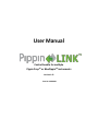
User Manual Control bundle for multiple Pippin PrepTM or BluePippinTM instruments Version 1.01 Part No. LNK-0001 Sage Science Inc. Suite 3150 500 Cummings Center Beverly, MA. 01915 © 2012 Sage Science, Inc. All rights reserved. Sage Science, Pippin Prep, BluePippin, and Pippin Link are trademarks of Sage Science, Inc. All other brands and name mentioned herein are property of their owners. 1 Table of Contents Introduction .................................................................................................................................................. 3 1 Unpacking .......................................................................................................................................4 2 Set-up .............................................................................................................................................5 3 Software Overview..........................................................................................................................6 The Main Screen ....................................................................................................................................... 6 Instrument Tabs ........................................................................................................................................ 7 The Instrument Interface .......................................................................................................................... 8 4 Using the Pippin Link Control Interface .................................................................................................... 9 1. Select the master instrument. ........................................................................................................ 9 2. Select the group instruments. ......................................................................................................... 9 3. Select the protocol to be shared by the group. ............................................................................ 10 4. Press the “Share Protocol button”. ............................................................................................... 11 5. Place the calibration fixture on the optical nests ........................................................................ 11 6. Close the lids on each instrument in the group. .......................................................................... 11 7. Press the “Calibrate” button ........................................................................................................ 12 8. Open the instrument lids and remove the optical calibration fixtures........................................ 13 9. Inspect and prepare the gel cassettes......................................................................................... 13 10. Place the gel cassettes into the instruments to be run. ............................................................. 13 11. Close all lids ................................................................................................................................. 13 12. Press the “Test Continuity” button ............................................................................................. 13 13. Open the lids to all instruments.................................................................................................. 14 14. Load samples and/or markers .................................................................................................... 14 15. Close the lids to all the instruments ........................................................................................... 14 16. Press “Start” Group ..................................................................................................................... 14 2 Introduction Thank you for purchasing the Pippin Link control bundle. Pippin Link includes all items required for the operation of group of Pippin Prep or BluePippin instruments from a single laptop computer. The Pippin Link will operate 1 to 7 units simultaneously. Specially modified Link-equipped Pippin instruments must be ordered. Please note the following important considerations: The Pippin Link control bundle and Pippin instruments will arrive preconfigured and userinstallable Pippin Prep and BluePippin instruments cannot be operated within the same group due to the incompatibility of cassette definitions. Installing additional instruments (that are not link-equipped) to a Pippin Link group requires hardware and software modifications to the instrument. Removing instruments from a Pippin Link group for the purpose of stand-alone use will required the installation of a monitor and keyboard and mouse. These items are not included with each link-equipped instrument purchases. However, a monitor, keyboard and mouse are included with the Pippin Link control bundle. 3 1 Unpacking The Pippin Control Bundle (LNK-0001) will arrive with the following components: Windows-based laptop computer with Pippin Link software installed. The application icon will appear on the desktop. 8-Port Ethernet Hub Switch (Netgear FS108 or similar) ethernet cable (to connect the laptop to the hub) Pippin Link user manual (this document) For stand-alone Pippin operation (not needed for Pippin Link operation): o Computer monitor o Keyboard, mouse, and mouse pad Pippin Link Desktop Icon Pippin (link-equipped) instruments will arrive (PIP-0002 or BLU0002) with the following components: Pippin Prep-L or BluePippin-L instruments Pippin Prep or BluePippin user manual Dummy VGA monitor connector Instrument Power Supply Ethernet cable (connects instrument to hub) Calibration fixture Rinse Cassette International plug adapter 4 2 Set-up Set up of the Pippin Link control bundle requires connecting the instruments and laptop to the Ethernet hub. Addresses are set in the software application and the connections to not need to be made in a sequential order. However it is recommended (though not essential) that all devices are completely powered up (the Pippin instruments should powered and the software launched, as outlined in the instrument user manual). Use the following guidelines: 1. Connect the dummy VGA connectors to the video monitor ports found on the back panel of the Pippin instruments. 2. Connect the Pippin power supplies to the back panel of the Pippin instruments. 3. Note the serial number on the back panel of the instrument. Place the Pippin Instruments on the lab bench in ascending order by serial number. In the software, the lowest serial number will map to Tab(1), etc. 4. Plug the Pippin power supplies into electrical outlets. 5. Power up each Pippin instrument by pressing the power buttons in the rear of the instruments. 6. Connect the power supply for the Ethernet Hub, and plug in the Ethernet power supply into an electrical outlet. 7. Connect the power supply for the laptop computer and power up the computer. 8. With Ethernet cables, connect the Pippin instruments (from the Ethernet ports on the back panel of the instruments) to the Ethernet ports on the Ethernet Hub. The cables do not need to be connected in any order into the hub. The instruments will be auto-detected by the Pippin Link software according to IP addresses that have been preset prior to shipment. 9. With an Ethernet cable, connect the laptop to the Ethernet Hub. 10. Launch the Pippin Link Application on the laptop PC. 5 3 Software Overview The Main Screen When the Pippin Link application has been started, the following screen will launch. The Main screen displays the status of every Pippin in the group. The adjacent tabs if pressed, will display the software interface in the individual Pippin instruments in the group. Group Status Group Commands 6 Instrument Tabs The Pippin instrument software interface is accessed by pressing The Tabs on the main screen. If an instrument in connected to the group, the instrument’s serial number will appear in the Tab heading. When an instrument is connected to the Pippin Link, the “Group Status” window will display the message “Idle”. Instrument interfaces Instrument Serial Number appears in Tab heading. Group Status will display “Idle” 7 The Instrument Interface Instrument Tab will provide access to the local instrument interface. Refer to the Pippin Prep or BluePippin operations manual for detailed instructions on monitoring, programming and analysis of Pippin DNA size selection. Note: In the instrument name may be edited in the System Options tab in the “Name” field. The default name is the instrument serial number. The name that appears in this field will appear in the Tab heading in the Pippin Link interface. 8 4 Using the Pippin Link Control Interface 1. Select the master instrument. One Pippin in the group of instruments must be selected a master. The protocols that are stored on the master instrument will be used to operate the group. 2. Select the group instruments. This should include all instruments to be run as a group, including the master. Select master and group instruments Instrument 1 is the master Instruments 1 and 2 are the group 9 When the master instrument is selected, the protocols stored on the master instrument will be displayed in the “Protocols”. With new instruments, this field will be empty. Refer to the Pippin Prep or BluePippin Operations Manual for instructions on programming protocols. The cassette definitions are shown in the “Cassettes” field. These are default definitions and must match the gel cassette product being used. Master run protocols list Cassette Definitions 3. Select the protocol to be shared by the group. The protocol will be highlighted in blue. The associated cassette definition will automatically highlight. 10 4. Press the “Share Protocol button”. The will load the protocol on all instruments in the group. The selected protocol will appear in the associated “Protocol” field in the group status area. Share Protocol appears in status area Share Protocol button 5. Place the calibration fixture on the optical nests of each instrument in the group. The dark side of the fixture should face down and completely cover the optical detectors. Proper placement of the calibration fixture 6. Close the lids on each instrument in the group. 11 7. Press the “Calibrate” button. The group status window will show the message “Calibrating” during the process. Group status field will display “Calibrating” Calibrate Group button If the calibration has been successful, the “Group Status” field will display the message “idle+cal”. If the calibration has failed, the message will revert to “idle”. Group Status will display “Idle+cal” 12 8. Open the instrument lids and remove the optical calibration fixtures. 9. Inspect and prepare the gel cassettes to be run on each instrument as outlined in the Pippin Prep and BluePippin Operations manuals. 10. Place the gel cassettes into the instruments to be run. 11. Close all lids. 12. Press the “Test Continuity” button. The group status window will show the message “continuity” during the process. Group status field will display “continuity” Test Continuity button If the continuity test has been successful, the “Group Status” field will display the message “idle+cal”. If the calibration has failed, the message will revert to “idle+cal”. Group Status will display “ready” 13 13. Open the lids to all instruments. 14. Load samples and/or markers at outlined in the Pippin Prep or BluePippin operations manuals. 15. Close the lids to all the instruments. 16. Press “Start” Group. Start Group button 17. The group may be paused, restarted or aborted. 14