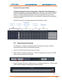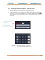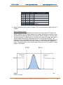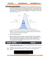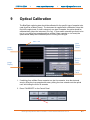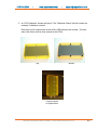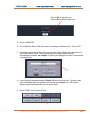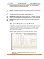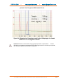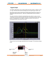
1
DNA Size Selection System Operations Manual Software v.6.00 Cassette Definition Set 10 978-744-2244 ● www.sagescience.com ● [email protected] Sage Science Inc. Suite 3150 500 Cummings Center Beverly, MA. 01915 © 2013 Sage Science, Inc. All rights reserved. Sage Science and BluePippin are trademarks of Sage Science, Inc. All other brands and name mentioned herein are property of their owners. BluePippin Operations Manual software v 6.00 cassette definition Set 10 ii 978-744-2244 ● www.sagescience.com ● [email protected] TABLE OF CONTENTS 1 INTRODUCTION .............................................................................................................. 1-1 2 SAFETY AND PRECAUTIONS ........................................................................................ 2-1 3 UNPACKING AND INSTALLATION ................................................................................ 3-1 4 ACHIEVING BEST RESULTS FROM THE BLUEPIPPIN ................................................ 4-1 5 SAMPLE PREPARATION ................................................................................................ 5-1 6 PROTOCOL PROGRAMMING GUIDE ............................................................................ 6-1 6.1 Overview .......................................................................................................................................... 6-1 6.2 Programming Summary ................................................................................................................. 6-2 6.3 Selecting a Cassette Definition ..................................................................................................... 6-4 6.4 Run Times ........................................................................................................................................ 6-5 6.5 Assigning a Reference Marker – external marker ....................................................................... 6-6 6.6 Assigning Reference Markers – internal standards ................................................................... 6-7 6.7 Warnings and Indicators ................................................................................................................ 6-8 7 PROGRAMMING SIZE SELECTIONS – TIGHT, RANGE, AND TIMED MODES ............ 7-1 7.2 Tight Mode – programming minimum size range collections ..................................................... 7-1 7.2 Range Mode– programming broad size range collections .......................................................... 7-3 7.9 Time Mode – programming timed collections ............................................................................. 7-4 8 PROGRAMMING DNA BAND CAPTURE WITH MIDORI GREEN - PEAK MODE ......... 8-1 9 OPTICAL CALIBRATION ................................................................................................ 9-1 10 PREPARING A CASSETTE ........................................................................................... 10-1 10.1 Visually Inspect the Cassette .................................................................................................... 10-1 10.2 Prepare the Cassette for Loading ............................................................................................. 10-3 10.3 Continuity Test ............................................................................................................................ 10-4 10.4 Adding Midori Green for Band Capture Cassettes ................................................................... 10-6 BluePippin Operations Manual software v 6.00 cassette definition Set 10 iii 978-744-2244 ● www.sagescience.com ● [email protected] TABLE OF CONTENTS (cont'd) 11 LOADING SAMPLES ..................................................................................................... 11-1 12 RUNNING A PROTOCOL .............................................................................................. 12-1 12.1 Overview ...................................................................................................................................... 12-1 12.2 Starting a Run .............................................................................................................................. 12-1 12.3 Monitoring a Run......................................................................................................................... 12-4 12.4 Log Files ...................................................................................................................................... 12-6 13 SAMPLE COLLECTION ................................................................................................ 13-1 13.1 Overview ...................................................................................................................................... 13-1 13.2 Intrinsic Sample Recovery on the BluePippin ......................................................................... 13-2 13.3 Improving Product Recovery with the Field Reversal ............................................................. 13-3 13.4 Improving Product Yield by Selecting a Wider Size Range ................................................... 13-4 14 SYSTEM VALIDATION .................................................................................................. 14-1 15 SYSTEM OPTIONS TAB ............................................................................................... 15-1 16 RUNNING IN MANUAL MODE ...................................................................................... 16-1 17 ANALYZING RUNS - LOG REVIEW TAB ...................................................................... 17-1 18 MANAGING FILES -- FILE MANAGER TAB ................................................................. 18-1 18.1 Overview ...................................................................................................................................... 18-1 18.2 File Types ..................................................................................................................................... 18-2 19 UPGRADING SOFTWARE ............................................................................................ 19-1 19.1 Extracting the Files to a USB flash drive ................................................................................. 19-1 19.2 Upgrading the Pippin Instrument Software ............................................................................. 19-3 20 WARRANTY AND SERVICE ......................................................................................... 20-1 21 ORDERING INFORMATION .......................................................................................... 21-1 22 INSTRUMENT SPECIFICATIONS ................................................................................. 22-1 BluePippin Operations Manual software v 6.00 cassette definition Set 10 iv 978-744-2244 ● www.sagescience.com ● [email protected] TABLE OF CONTENTS (CONT'D) 23 GEL CASSETTES SPECIFICATIONS ........................................................................... 23-1 23.1 3% Agarose, Dye-Free, 90 bp-250 bp, Marker Q2 (internal standards) ........................... 23-2 23.2 2% Agarose, Dye-Free, 100 bp-600 bp, Marker V1 (internal standards) .......................... 23-3 23.3 2% Agarose, Dye-Free, 100 bp-600 bp, Marker X1 (int stds, 25 l elution well)............... 23-4 23.4 2% Agarose, Dye-Free, 100 bp-600 bp, Marker M1 (external marker) .............................. 23-5 23.5 1. 5% Agarose, Dye-Free, 250 bp-1.5 kb, Marker R2 (internal standards) ...................... 23-6 23.6 1.5% Agarose, Band Capture, 250 -1500 bp, Marker A1 (external marker) ..................... 23-7 23.7 0.75% Agarose, Band Capture, 2-10 kb, Marker D1, Pulsed-Field (external marker) ...... 23-8 23.8 0.75% Agarose, Dye-Free, 1-6 kb, Marker S1, Low Voltage (external marker) ................. 23-9 23.9 0.75% Agarose, Dye-Free, 1-6 kb, Marker S1, Pulsed-Field (external marker) ............. 23-10 23.10 0.75% Agarose, Dye-Free, 5-10 kb, Marker S1, Pulsed-Field (external marker) ........... 23-11 23.11 0.75% Agarose, Dye-Free, 10-18 kb, Marker U1, Pulsed-Field (external marker) ......... 23-12 23.12 0.75% Agarose, Dye-Free, 18-27 kb, Marker T1, Pulsed- Field (external marker)......... 23-13 23.13 0.75% Agarose, High Range Targets, Marker W1, Pulsed- Field (ext mrk, 40 & 50kb) 23-14 BluePippin Operations Manual software v 6.00 cassette definition Set 10 v 978-744-2244 1 ● www.sagescience.com ● [email protected] Introduction Thank you for purchasing the BluePippin from Sage Science. The BluePippin is an automated preparative gel electrophoresis system. We urge you to read this manual to familiarize yourself with the system’s capabilities and precautions. System Overview There are three components to the BluePippin system: Instrument – The instrument contains an epifluorescence detector, an electrophoresis power supply, an electrode array, and a Linux-based singleboard computer. The system computer is accessed by an external LCD monitor, mouse, and keyboard. The electrode array is located in the top of the sliding instrument cover and is not user-accessible. Software – System software allows the user to enter parameters that define the DNA fragment size ranges or DNA bands that are to be collected. The software also logs fluorescence and electrical current data which may be analyzed in a review screen. Gel Cassettes – Pre-cast, disposable agarose cassettes are manufactured by Sage Science. Cassettes are supplied in kits that contain 10 cassettes and sufficient reagents to complete all collections. Kits have been developed to address DNA size range collections at various size ranges, or DNA band capture. Please refer to Section 21 for kit descriptions and ordering numbers. Collection Strategies Cassette kits employ the following strategies: For Size Selection of smaller DNA fragments (90 bp – 1.5 kb): Dye-free gels with labeled internal standards –Fluorescein labeled DNA internal standards are added to samples when run. The rates of migration of the internal standards are used to determine the collection timing* within the sample lane. Up to five samples may be run per cassette. The DNA sequence of internal standards may be found at www.sagesscience.com/support. BluePippin Operations Manual software v 6.00 cassette definition Set 10 1-1 978-744-2244 ● www.sagescience.com ● [email protected] For Size Selection of large DNA fragments (>2kb): Dye-free gels with labeled external marker – A fluorescein labeled DNA marker set is loaded in a dedicated sample lane during a run. The rates of migration of the markers are used to determine the collection timing* the remaining sample lanes. Four samples and one DNA marker must be run per cassette. For DNA Band Capture (>2 kb): DNA binding dyes with external standards -- A DNA marker set is loaded in a dedicated sample lane during a run. A DNA binding dye (Midori Green) is loaded into the (+) buffer chambers of the separation channels of all sample lanes. During electrophoresis, the DNA binding dye enters the gel and provides fluorescent detection of the DNA bands and markers. The rates of migration of the markers are used to determine the band capture thresholds in the remaining sample lanes. Four samples and one DNA marker must be run per cassette. DNA binding dye must also be added by the user. * Collection timing (start, duration, and end) is also based on the factory calibration settings in the cassette definition file, and the user-input size range settings in a run protocol (Section12). BluePippin Operations Manual software v 6.00 cassette definition Set 10 1-2 978-744-2244 2 ● www.sagescience.com ● [email protected] Safety and Precautions Icons Used In this manual, the following icons will be used to provide the user with information pertinent to the use of the BluePippin. Caution! Warns the user that injury or instrument damage may occur if the contents of the warning are not properly followed. High Voltage! Warns of the risk of electrical shock if the contents of the warning are not properly followed. Important! Provide important information about the proper use of the system that may influence the quality of the result. Information. Provides additional information regarding the function of the system or applications for which is used. Safe Use Guidelines The BluePippin system is designed to operate under the following environmental conditions: Pollution Degree 2 Installation category 2 Altitude 2000m Indoor use Ambient temperature 17-32oC Humidity 10-80%, non-condensing Standard laboratory precautions should be taken when handling BluePippin Gel cassettes and operating the BluePippin: Wear a lab coat, safety glasses, and gloves. Use in proximity of an eye wash station and/or running water. BluePippin Operations Manual software v 6.00 cassette definition Set 10 2-1 ● 978-744-2244 3 www.sagescience.com ● [email protected] Unpacking and Installation Unpacking the BluePippin The BluePippin Instrument The BluePippin instrumentation is shipped in two boxes: one will contain the BluePippin and Accessories and the second box will contain the computer monitor in the manufacturer’s original packaging. With the boxes in the upright position, open and confirm that the following items are enclosed: Monitor LCD computer monitor Video cable Power cord BluePippin BluePippin Instrument Accessory box o Computer keyboard, USB o Computer mouse, USB o Power supply o Plug adapter (adapts non-U.S. power cords, see Figure 3.1) o Power cord o Rinse cassette (for maintenance of electrodes) o Calibration cassette (for setting optical baseline before each run) Figure 3.1. Adapter plug for non-US power cord installation. BluePippin Operations Manual software v 6.00 cassette definition Set 10 3-1 978-744-2244 ● www.sagescience.com ● [email protected] Setting up the BluePippin 1. Remove the accessory box located on inside edge of box at the front end of the instrument. Remove the keyboard, mouse, and instrument power supply from their packaging. 2. Firmly grip both sides of the instrument and lift it from the foam packaging insert. The BluePippin weighs approximately 14 lbs. Place the Pippin on a table or bench top. 3. Remove the computer monitor from the manufacturer’s box and connect the monitor to BluePippin using supplied video cable. Connect monitor to power using power supply supplied with monitor. 4. Insert USB connector from computer key board into port located in the back of the Instrument. 5. Connect mouse to BluePippin via USB or PS2 connector at back of instrument. 6. Connect monitor cable into the video port located in the back or the instrument. 7. Connect monitor to power using power supply and cords supplied with monitor. 8. Connect BluePippin instrument to power via supplied power supply and cable. Power connector is at rear of instrument. 9. Press power switch located on the rear of the instrument, and wait for software to launch (approximately 30 seconds). The BluePippin is ready for use. The software should automatically launch – allow 30 seconds. Figures 3.2 and 3.3 on the next page show the rear panel of the BluePippin. Figure 3.4 on the following page shows the front panel. BluePippin Operations Manual software v 6.00 cassette definition Set 10 3-2 978-744-2244 ● www.sagescience.com ● [email protected] USB Ports (4) VGA monitor port Power Switch Figure 3.2. Rear Panel Ports Power Entry Port Mouse Key board Monitor Cable Power Cable Figure 3.3. Rear Panel Connections BluePippin Operations Manual software v 6.00 cassette definition Set 10 3-3 978-744-2244 ● www.sagescience.com ● [email protected] Figure 3.4. BluePippin front panel. USB Port Indicator Light: Green when electrophoresis is underway (protocol is running). Indicator Light: Blue when instrument is ready for use (power is on, and software is active).* BluePippin Operations Manual software v 6.00 cassette definition Set 10 3-4 978-744-2244 ● www.sagescience.com ● [email protected] Unpacking Gel Cassettes Gel cassettes are shipped in boxes in the following configurations. Ensure boxes are in the upright position and confirm that following contents are present: Dye-free gels with internal standards (50 samples, size selections 90 bp – 1.5 kb): o o o 10 foil-sealed gel cassettes (store at R.T.) 1 package of adhesive tape for sealing elution wells 1 reagent kit for 10 cassettes (store at 4 oC) 550 μl DNA internal standards/ loading solution mix (10 μl/sample) 40 ml of spare running buffer Dye-free gels with labeled external marker (40 samples, size selections >2kb): o o o 10 foil-sealed gel cassettes (store at R.T.) 1 package of adhesive tape for sealing elution wells 1 reagent kit for 10 cassettes (store at 4 oC) 40 ml of spare running buffer 440 μl DNA size markers (1 x 40 μl load/ cassette) 500 μl loading solution (10 μl/sample) 2 X 800 l 0.1% Tween20 in running buffer* 40 ml of spare running buffer DNA binding dyes with external marker o o o 10 foil-sealed gel cassettes (store at R.T.) 1 package of adhesive tape for sealing elution wells 1 reagent kit for 10 cassettes (store at 4 oC) 40 ml of spare running buffer 440 μl DNA size markers (1 x 40 μl load/ cassette) 500 μl loading solution 2 X 800 l 0.1% Tween20 in running buffer* 2 X 1.1ml Midori Green DNA binding dye (40 μl/ buffer chamber) * Tween solution is used to improve DNA recovery of larger DNA fragments. BluePippin Operations Manual software v 6.00 cassette definition Set 10 3-5 978-744-2244 ● www.sagescience.com ● [email protected] Important! Fluorescein labels will degrade at room temperature – minimize time at RT for labeled standards and markers Storage Conditions for Cassettes and Reagents The following storage requirements should be observed: Gel Cassettes- Store at room temperature in the foil bags until ready for use. DNA Markers (unlabeled) – store at 4oC. DNA Internal standards and markers (labeled) – store at 4oC minimimize time at room temperature. Electrophoresis buffer – may be stored at room temperature or 4 oC Loading solution – store at 4 oC. Bring to room temperature before use. Tween Solution – store at 4 oC Midori Green DNA binding dye – store at 4oC BluePippin Operations Manual software v 6.00 cassette definition Set 10 3-6 978-744-2244 4 ● www.sagescience.com ● [email protected] Achieving Best Results from the BluePippin The BluePippin extracts narrow or wide DNA size distributions more reproducibly and with higher yield than manual preparative gel techniques. However, due to the unique design of the pre-cast gel cassette, there are key differences between running the Pippin and other agarose gel methods. 4.1 Successful Operation It is recommended that users closely follow the instructions outlined in the following sections (Section 5-8) until they become thoroughly familiar with the system. The Quick Guide (included with cassettes) provides protocol reminders, but is not intended for beginning users. The keys to successful operation are: Purity of the input sample (See Section 5) Optical Calibration (Section 9) Preparation of the cassettes (Section 10) Sample loading (See Section 11) 4.2 Common Misconceptions Users should be aware of the following characteristics of the BluePippin System. These are part of normal operation of the system, but may seem counterintuitive at first. 4.2.1 Narrowest is not always the best. The BluePippin can produce very narrow size distributions from sheared genomic DNA. However, narrower size distributions will necessarily mean that a smaller fraction of the input DNA will be recovered. Users should broaden their collection ranges if the default tight settings do not produce enough DNA for their application. See Section 13.4 for details. Figure 4.1. A comparison of the relative sample yield between tight and broader size selections of DNA. BluePippin Operations Manual software v 6.00 cassette definition Set 10 range 4-1 978-744-2244 ● www.sagescience.com ● [email protected] 4.2.2 DNA undergoing elution is smaller than DNA at the detector. The branch point between the separation and elution channels is downstream from the detector position. Figure 4.2 shows a cassette channel to illustrate. During normal operation, the leading edge of the DNA fraction scheduled for elution passes the detector before the start of elution (by up to several minutes). This offset can give rise to the impression that sample elution is late, even in runs that are functioning properly. Figure 4.2. An illustration of the time and base pair difference between the detector and branch point. 4.2.3 The rate of electrophoresis is faster in the separation channel than in the elution channel. This may cause misconceptions with regard to the timing of broad size selections. For instance, if one sample is programmed to select from 400 – 600bp, and a second sample is programmed to select from 200 – 600 bp, the narrower range will finish eluting before the broader one, even though both elutions complete collection at 600 bp. The collections of large DNA fragments, especially with pulsed –field protocols, can also appear counter-intuitive with respect to timing. Figure 4.3. An illustration comparing the relative rate of electrophoresis in the separation and elution channels BluePippin Operations Manual software v 6.00 cassette definition Set 10 4-2 978-744-2244 5 ● www.sagescience.com ● [email protected] Sample Preparation Input Sample Characteristics When running the BluePippin, characteristics of input DNA can affect separation resolution and efficiency of product recovery. The following general guidelines should be followed: Ionic strength: The ionic strength of the sample should be lower than the ionic strength of the buffer (80mM monovalent ions). High salt concentrations can result in slower than expected DNA mobility. Protein in the sample: DNA-binding proteins such as ligases or polymerases can affect the mobility of fragments during separation. Proteins can also reduce DNA recovery from the elution module by increasing the binding of DNA to the ultrafiltration membrane at the back of the elution module. For best results, samples should be de-proteinized prior to loading whenever possible. Input DNA size distribution: A knowledge of the input size distribution is obviously important to program accurate size selection settings. BluePippin cassettes are calibrated using the Agilent Bioanalyzer to evaluate input and product sizes, and so, for best results, input size distributions should be evaluated using the Bioanalyzer. For low concentration samples, the Agilent HS chip is very useful . Preparing DNA Samples for the BluePippin 1. 2. 3. 4. Bring DNA sample up to 30μl with TE. Bring loading solution to room temperature. For each sample, combine 30μl of DNA sample with 10μl of loading solution. Mix samples thoroughly (vortex mixer). Briefly centrifuge to collect. Recommended sample Load Guidelines Maximum Load: 10g sheared genomic DNA 2 g restriction/PCR band capture Minimum Load: low single nanograms, sheared genomic DNA 50 ng restriction/PCR band capture Optical Sensitivity (Midori-Green cassettes): approx. 10-15ng single bands, restriction fragments, PCR products, or synthetic DNA fragments BluePippin Operations Manual software v 6.00 cassette definition Set 10 5-1 978-744-2244 6 ● www.sagescience.com ● [email protected] Protocol Programming Guide The default screen on the BluePippin is a tabbed format. The Protocol Editor is the second tab. 6.1 Overview The protocol editor tab is the screen with which users create new protocols, or edit existing protocols, for DNA size selection. A protocol is created for a cassette type (within the applicable target range) and is saved as a named protocol file with a “.ppprot” file extension.. When running a cassette, an appropriate protocol file is selected and applied to the run. A protocol file may be applied to any run, provided the cassette type is correct. Protocol Editor Tab Protocol Name Cassette Type Selector Run Time End Selector Protocol Parameters DNA Marker/Standards Lane Assignment Warnings Text Box File Commands BluePippin Operations Manual software v 6.00 cassette definition Set 10 6-1 978-744-2244 ● www.sagescience.com ● [email protected] Protocol Parameters Detail The protocol parameters section is shown below. Users will select a programming mode for each sample, and a lane to designate as a reference. Then, the size selection values are entered either as base pair (BP) values, or time values (hr:min:sec in “Time” mode). For “Peak” programming mode, users enter a base pair value into the “BP Thresh” field, the instrument will collect the next peak that it detects after that threshold has been reached. Individual lanes may have different parameters and different modes. Programming Modes 6.2 Ref. Lane Indicators Base Pair (BP) (Tight and Range modes) parameters Time mode parameters Peak mode parameters Programming Summary The following is a summary of the steps required to program a protocol. Detailed instructions are provided in the subsequent sections. 1. Click the “Protocol Editor” tab along top of the screen. 2. Select “NEW”, to create a new protocol. To edit an existing protocol, press the “LOAD” button to select the protocol to be edited. 3. Select a Cassette Type from “Cassette” menu, by clicking the folder icon. Protocol fields cannot be edited unless a cassette type has been selected. BluePippin Operations Manual software v 6.00 cassette definition Set 10 6-2 978-744-2244 ● www.sagescience.com ● [email protected] 4. Make sure the “End Run when Elution is Completed” box is checked. This will end the run at the earliest possible time, after the final elution is complete. Information. The 8 hour run value is a default value that ensures most runs will be completed if the “End Run when Elution Completed” box is left unchecked. 5. Program the size selection protocol, and assign the DNA reference marker lane. There are four modes of programming on the BluePippin: Tight – collects minimum allowable distribution range of DNA fragments using the median target base pair value. Range – allows users to select the range to be collected using starting and ending base pair values. Time – allows users to program extractions using the starting and ending elution time (hr:min:sec) values only (a reference DNA marker is not used) Peak – collects the next peak (restriction fragment or PCR band) after the set threshold base pair value has been reached. Note: Programming modes may be independently applied to individual sample lanes 6. Enter Sample ID or description (optional). BluePippin Operations Manual software v 6.00 cassette definition Set 10 6-3 ● 978-744-2244 www.sagescience.com ● [email protected] 7. Press “Save As” button, enter a name for the protocol. 6.3 Selecting a Cassette Definition Cassettes are selected from a menu tree with the up to 3 tiers. Users should select the appropriate definition from the 2nd or 3rd tier: % Agarose – the percentage agarose of the cassette 3% 1.5% 0.75% o Range –If the same type of cassette requires a different electrophoresis protocol, the cassette will be selected by target size range and the type of electrophoresis protocol: o o o o o 1 – 6 kb Low Voltage 1 – 6 kb Pulsed Field 3 – 10 kb Pulsed Field 13 – 33 kb Pulsed Field 20 – 50 kb Pulsed Field BluePippin Operations Manual software v 6.00 cassette definition Set 10 6-4 978-744-2244 ● www.sagescience.com ● [email protected] 6.4 Run Times Protocols can be run with widely variable run times – up to 7 hours for low voltage runs. The Run Time Selector consists of a field and a check box, with the following default settings. The 8 hour default value in the Run Time field ensures that a run is not unintentionally ended early. The checked box in the “End Run when Elution is Completed” field will automatically end a run when every lane that has a programmed elution has completed its collection. Users may adjust the desired run time by referring to Section 21, where estimated run times are listed for each cassette definition. Users should be aware of the following when adjusting the run time parameters: If a run time is entered based on run time estimates from Section 21, make sure adequate time is added to the estimate as a safety The “Run Time” field will take precedence—When the run time is achieved, the run will end regardless of whether the elutions are complete. To end a run manually, go to the Main Tab and press “STOP”. Completed elutions may be verified in the Lane Status Panel if there is a value is in the “Elution Timer” field and the “Separate” button is lit: BluePippin Operations Manual software v 6.00 cassette definition Set 10 6-5 978-744-2244 6.5 ● www.sagescience.com ● [email protected] Assigning a Reference Marker – external marker 1. Determine the lane into which the reference marker will be loaded. 2. In the protocol editor, enter the reference lane designation into “Ref Lane” field for every cassette lane. Click “APPLY REFERENCE TO ALL LANES”. Figure 6.1 shows the proper settings for running a DNA marker in lane 1, with programmed “Tight” extractions in lanes 2-5. Lane to which marker has been loaded. Remaining lanes will reference off of marker lane Figure 6.1. The correct configuration for a protocol with an external marker loaded in lane 1. BluePippin Operations Manual software v 6.00 cassette definition Set 10 6-6 978-744-2244 6.6 ● www.sagescience.com ● [email protected] Assigning Reference Markers – internal standards 1. Markers must be loaded into every lane with the sample (30 ul of sample with 10 ul of internal standard loading solution). 2. In the protocol editor, press “USE INTERNAL STANDARDS”. This will auto-fill the “Ref Lane” fields with reference marker internal to the sample. The software will determine the timing of elution based on the migration of the DNA marker within its own lane. 3. Figure 6.2 shows the correct assignation of marker lanes for internal standard runs. All lanes will reference off of internally loaded standard Figure 6.2. The correct configuration for a protocol using internal standards. Important! When using internal standards all samples must be prepared the BluePippin internal standard loading solution which is formulated for the cassette type and size range to be used. The internal standard loading solution contains the markers. BluePippin Operations Manual software v 6.00 cassette definition Set 10 6-7 978-744-2244 6.7 ● www.sagescience.com ● [email protected] Warnings and Indicators BP Range Flag When a Minimum Size Range has been programmed into a sample lane, the “BP Range Flag” field for that sample will display “tight” and a green color. When a broad size cut range (larger than the minimum) has been programmed into a sample lane, the “BP Range Flag” field for that sample will display “broad” and an orange color. Pause Enabled Indicator If the pause feature has been entered for a sample lane, “Pause On” indicator will be displayed. BluePippin Operations Manual software v 6.00 cassette definition Set 10 6-8 978-744-2244 ● www.sagescience.com ● [email protected] Warnings Text Box If there are errors or exceptions within a programmed protocol, a message will appear in the Warnings text box identifying the nature of the discrepancy. BluePippin Operations Manual software v 6.00 cassette definition Set 10 6-9 978-744-2244 7 ● www.sagescience.com ● [email protected] Programming Size Selections – Tight, Range, and Timed Modes 7.2 Tight Mode – programming minimum size range collections The “Tight” programming mode is a method for selecting DNA size range collections by entering a target base pair value in software. The system will collect the minimum fragment distribution that is possible, centered on this base pair value. For size reference, either internal DNA standard or external DNA markers (run in a separate lane) may be used, depending on cassette type and/or application. Cassette kits for smaller DNA size range collections (90-1500 bp) use internal standards and larger collections (>2 kb) require use of one cassette lane to run and external reference marker. Assignation of reference DNA is detailed in Sections 6.5 and 6.6. In the protocol editor: 1. Select an appropriate cassette type for size selection, if a new protocol is being created. 2. Assign the internal or external reference DNA. a. For cassettes using internal standards: i. press the “USE INTERNAL STANDARDS” button. b. For cassettes using an external marker lane: i. enter the lane into which the marker will be loaded, into the “Reference Lane” field (“1” is the default value) ii. press the “APPLY REFERENCE TO ALL LANES” button. 3. Select the “Tight” programming mode. Click the “Tight” button everly lane in which the “Tight” fragment range will be collected. If using and external marker, make sure no collection modes are selected for that lane. 4. Enter a value in for the “BP Target”. This value should represent the median value for the desired size range to be collected. The actual range to be collected will auto-fill the “BP Start” and “BP End” fields. BluePippin Operations Manual software v 6.00 cassette definition Set 10 7-1 978-744-2244 ● www.sagescience.com ● [email protected] 5. (Optional) Enter a BP pause value. If a value is entered into the pause field, the system will pause when it has estimated that that base pair value has been collected during the elution of that lane. A pause will allow a user to remove two consecutive cuts from a sample. The two cuts will usually have overlapping size distributions. User may wish to use the pause feature for two reasons: 1) to retrieve nearly identical cuts from the same sample, or 2) to avoid overflow of the elution module during collections that require a long elution period. The BP pause value must be within the extraction range (between BP Start and BP End). The pause function temporarily turns off power to the electrodes and suspends run timers, allowing users to remove the sample, rinse the elution well (if desired), and then resume the instrument run to collect additional sample. Important! A pause will require the user to manually resume the protocol from the Main Screen controller. The instrument lid may be opened during the pause, and sample retrieved. 6. Enter Sample ID information. Important! Minimum size ranges are may not be the ideal for some applications. Very narrow size ranges collect less DNA than larger ranges. Users should consider the requirement for distribution vs. yield (see sec. 11-4). 7. Save. After programming a new protocol, or editing an existing one, the protocol file must be saved prior to use. If the protocol is new, press “Save”. If a protocol has been edited, a yellow alert will be displayed in the “Protocol Changes Not Applied” field. “Save” will save the file under the previously saved name, and “Save As” will allow a new name for the file to be applied. All protocol files are saved in a directory; /home/pippin/BluePippin/Protocols, and may be accessed in the File Manager tab. BluePippin Operations Manual software v 6.00 cassette definition Set 10 7-2 978-744-2244 ● www.sagescience.com ● [email protected] 7.2 Range Mode– programming broad size range collections The “Range” programming mode is a method for selecting DNA size range collections by a starting and ending base pair value in software. The system will collect the fragment range between the start and end base pair values. This option should be used when collections that are broader than the minimum are required. For size reference, either internal DNA standard or external DNA markers (run in a separate lane) may be used, depending on cassette type and/or application. Cassette kits for smaller DNA size range collections (90-1500 bp) use internal standards and larger collections (>2 kb) require use of one cassette lane to run and external reference marker. Assignation of reference DNA is detailed in Sections 6.5 and 6.6. In the protocol editor: 1. Select an appropriate cassette type for size selection, if a new protocol is being created. 2. Assign the internal or external reference DNA. a. For cassettes using internal standards: i. b. press the “USE INTERNAL STANDARDS” button. For cassettes using an external marker lane: i. ii. enter the lane into which the marker will be loaded, into the “Reference Lane” field (“1” is the default value) press the “APPLY REFERENCE TO ALL LANES” button. 7. Select the “Range” programming mode. Click the “Range” button for the lane from which the cut will be extracted. If using and external marker, make sure no collection modes are selected for that lane. 8. Enter a range values in the “BP Start” and “BP End” fields. The median target value of the collection range will auto-fill the “BP Target” field. 9. (Optional) Enter a BP pause value. If a value is entered into the pause field, the system will pause when it has estimated that that base pair value has been collected during the elution of that lane. A pause will allow a user to remove two consecutive cuts from a sample. The two cuts will usually have overlapping size distributions. User may wish to use the pause feature for two reasons: 1) to retrieve nearly identical cuts from the same sample, or 2) to avoid overflow of the elution module during collections that require a long elution period. The BP pause value must be within the extraction range (between BP Start and BP End). The pause function temporarily turns off power to the electrodes and suspends run timers, allowing users to remove the sample, rinse the elution well (if desired), and then resume the instrument run to collect additional sample. Important! A pause will require the user to manually resume the protocol from the Main Screen controller. The instrument lid may be opened during the pause, and sample retrieved. BluePippin Operations Manual software v 6.00 cassette definition Set 10 7-3 978-744-2244 ● www.sagescience.com ● [email protected] Enter Sample ID information 10. Save. After programming a new protocol, or editing an existing one, the protocol file must be saved prior to use. If the protocol is new, press “Save”. If a protocol has been edited, a yellow alert will be displayed in the “Protocol Changes Not Applied” field. “Save” will save the file under the previously saved name, and “Save As” will allow a new name for the file to be applied. All protocol files are saved in a directory; /home/pippin/BluePippin/Protocols, and may be accessed in the File Manager tab. 7.9 Time Mode – programming timed collections Important! The time mode does not reference a standard. Cassette to cassette variablity and environmental running conditions will cause a wide variation in selection accuracy. The “Range” programming mode is a method for crude DNA collections where accuracy of the fragment size or range is not critical. The system will collect the fragment range between the elution start time and elution end time. In the protocol editor: 1. Select the “Time” programming mode. Click the “Time” button for the lane from which the cut will be extracted. A DNA marker reference standard is not required. 2. Enter a time values in the “T Start” and “T End” fields. Sample elutions will occur at exactly those times after the start of the run 3. (Optional) Enter a Time pause value. If a value is entered into the pause field, the system will pause at that time after the start of a run. A pause will allow a user to remove two consecutive cuts from a sample. The two cuts will usually have overlapping size distributions. User may wish to use the pause feature for two reasons: 1) to retrieve nearly identical cuts from the same sample, or 2) to avoid overflow of the elution module during collections that require a long elution period. The T pause value must be within the extraction range (between T Start and T End). The pause function temporarily turns off power to the electrodes and suspends run timers, allowing users to remove the sample, rinse the elution well (if desired), and then resume the instrument run to collect additional sample. Important! A pause will require the user to manually resume the protocol from the Main Screen controller. The instrument lid may be opened during the pause, and sample retrieved. BluePippin Operations Manual software v 6.00 cassette definition Set 10 7-4 978-744-2244 4. ● www.sagescience.com ● [email protected] Enter Sample ID information. 5. Save. After programming a new protocol, or editing an existing one, the protocol file must be saved prior to use. If the protocol is new, press “Save”. If a protocol has been edited, a yellow alert will be displayed in the “Protocol Changes Not Applied” field. “Save” will save the file under the previously saved name, and “Save As” will allow a new name for the file to be applied. All protocol files are saved in a directory; /home/pippin/BluePippin/Protocols, and may be accessed in the File Manager tab. BluePippin Operations Manual software v 6.00 cassette definition Set 10 7-5 978-744-2244 8 ● www.sagescience.com ● [email protected] Programming DNA Band Capture with Midori Green - Peak Mode Band Capture cassettes are used to collect DNA bands such as PCR or restriction fragments. These cassette require the addition of an DNA binding dye (Midori Green) to the (+) buffer chambers of the separation channels of the sample lanes (see Section 9.4). Band capture uses the “Peak” mode for programming. Using “Peak” mode, a base pair value is entered into a “threshold” field. The BluePippin will collect the next band that the system detects after the programmed base pair threshold. The amount of DNA loaded should be between 50 ng – 2 g/band. Larger band (>0.5g), require additional programming modification to account for band broadening. “Peak” mode requires the use of an external marker for reference. In the protocol editor: 1. Select an appropriate cassette type for size selection, if a new protocol is being created. 2. Assign external reference DNA marker a. enter the lane into which the marker will be loaded, into the “Reference Lane” field (“1” is the default value) b. press the “APPLY REFERENCE TO ALL LANES” button. 3. Select the “Peak” programming mode. Click the “Peak” button for the lane from which the fragment peak will be extracted. 4. Enter a value in for the “BP Threshold”. Enter a base pair value that precedes the beginning of peak/band of the fragment to be collected. If possible, use a threshold value that is <80-90% of the beginning of the leading edge of the target band. The BluePippin will automatically collect the next peak that is detected. The mass of minimum detectable band is approximately 50 ng. Peak collection cannot be used with dye-free cassettes. Important! It is important to verify the size of the band by electrophoresis (Agilent Bioanalyzer, agarose gel). BluePippin Operations Manual software v 6.00 cassette definition Set 10 8-1 978-744-2244 ● www.sagescience.com ● [email protected] 5. Adjust “Expansion” factor values, if needed. This is recommended for loads above 0.5 g/band. About Expansion factors: When the optical detector identifies a band (this occurs when, post-“BP Thresh”, the signal increases over 10% above baseline), the system will determine collection timing, and estimate the peak size, based on the reference marker calibration. As is the case with size selections in “tight” mode, the instrument will determine the base pair value at which to begin collection (BP Start) and at which to end collection (BP End). The expansion values, with default values of 0.9 and 1.10, respectively, automatically widen this range to ensure that the entire peak is collected. This is illustrated in Figure 8.1, below. Expansion factors values may be used to widen or narrow the collection criteria, based on user needs. Figure 8.1. Expansion factors values widen the peak collection timing to ensure complete capture of the peak. BluePippin Operations Manual software v 6.00 cassette definition Set 10 8-2 978-744-2244 ● www.sagescience.com ● [email protected] Expansion factors for larger sample loads. For sample loads of 0.5 g/band and below, the default expansion factors should result in successful collection of the entire DNA band. Higher sample loads will migrate slower relative to the reference markers, and exhibit band broadening. I these instances, users should increase the “End Exp” values to capture the full amount of DNA. The “Start Exp” should remain at 0.90. This is illustrated in Figure 8.2. The maximum “End Exp” value that might be required is 1.50. Figure 8.2. Default values for sample loads of 5 ug and below should be sufficient for most collections. Larger sample loads will require higher “End Exp” values to collect the entire band. “Start Exp” values needn’t be adjusted for larger loads. 6. Enter Sample ID information 7. Save. After programming a new protocol, or editing an existing one, the protocol file must be saved prior to use. If the protocol is new, press “Save”. If a protocol has been edited, a yellow alert will be displayed in the “Protocol Changes Not Applied” field. “Save” will save the file under the previously saved name, and “Save As” will allow a new name for the file to be applied. All protocol files are saved in a directory; /home/pippin/BluePippin/Protocols, and may be accessed in the File Manager tab. Important! During band collection, optical detection is turned off. This may cause the detection of band to appear clipped (see image below). This appearance is normal, and should be expected. Typical optical trace from a band capture run. BluePippin Operations Manual software v 6.00 cassette definition Set 10 8-3 978-744-2244 9 ● www.sagescience.com ● [email protected] Optical Calibration The BluePippin optical system should be calibrated for the specific type of cassette to be used (dye-free or Midori Green). The instrument is supplied with a calibration fixture that fits into the optical nest. If a lab is using only one type of cassette, the optics should be calibrated daily (when the instrument is in use). If users switch cassette type that is to be run (e.g. run a dye-free cassette and then a Midori Green cassette or vice versa) the optics should always be re-calibrated prior to running the new type. Main Tab Lane Status Panel Graph Display Protocol Status Panel Image Display Control Panel 1. If switching from a Midori Green cassette to a dye-free cassette, rinse the electrode array by filling the rinse cassette with water, placing the rinse cassette onto the optical nest, and closing the lid for 20 seconds. 2. Press “CALIBRATE” on the Control Panel BluePippin Operations Manual software v 6.00 cassette definition Set 10 9-1 978-744-2244 ● www.sagescience.com ● [email protected] 3. An “LED Calibration” window will launch. The “Calibration Status” field will contain the message “Calibration not done”. Place fixture on the optical nest so that all five LED detectors are covered. The dark side of the fixture must be down (closest to the LEDs): Bottom Top Correct Position on Optical Nest BluePippin Operations Manual software v 6.00 cassette definition Set 10 9-2 978-744-2244 ● www.sagescience.com ● [email protected] 4. Close the lid. 5. To calibrate dye-free cassettes, the LED Calibration setting (Target I ph, mA) must be ‘0.60’. To calibrate cassettes using DNA binding dye (Midori Green), the LED Calibration setting must be ‘0.30’. Enter ‘0.60’ for dye-free runs Enter ‘0.30’ for Midori Green runs 6. Press “CALIBRATE” BluePippin Operations Manual software v 6.00 cassette definition Set 10 9-3 978-744-2244 ● www.sagescience.com ● [email protected] 7. The LED photocurrents will automatically adjust to a factory setting, and the “Calibration Status” field will contain the message “Calibration OK”. 8. Press “EXIT” to return to the Main Tab. BluePippin Operations Manual software v 6.00 cassette definition Set 10 9-4 978-744-2244 10 ● www.sagescience.com ● [email protected] Preparing a Cassette 10.1 1. Visually Inspect the Cassette Remove the cassette from foil packaging. Foil package is scored at one end to allow tearing. 2. Inspect the levels of buffer in the buffer reservoirs. Tip the cassette to consolidate any bubbles in the reservoirs, then hold the cassette in a horizontal position and look at the reservoirs from the top and bottom edges. Reservoirs should be nearly full of buffer and roughly equal in volume across the cassette. If the buffer level in any reservoir appears less than 50% full (compared with its neighbors), the low reservoir should be refilled prior to running. When refilling, a visual check of buffer levels is sufficient -- a measured volume is not required. (+) side of cassette buffer volumes are Low (-) side of cassette Figure 6.1. Low buffer levels in cassette buffer chambers. 3. Inspect the gel columns. Look for obvious breakage of the agarose column in each channel. Important! If there is obvious breakage, do not use the lane. Remaining lanes can be used. BluePippin Operations Manual software v 6.00 cassette definition Set 10 10-1 978-744-2244 ● www.sagescience.com ● [email protected] 4. Inspect bottom of cassette for bubbles in the detection region of the gel columns. If a cassette has been jarred during shipping, the agarose column can delaminate from the plastic bottom of the separation channel, forming a thin flat bubble between the gel column and the bottom of the channel. If this happens in the region used by the optical detector (see illustration), DNA detection will be extremely unreliable. If a lane with such a bubble is used for the reference marker, the markers will not be properly identified and sample collection will occur at the wrong time or fail altogether. (Only the optical properties of the channel are affected -- electrophoretic properties of the channel are unaffected, since the DNA travels through the center of the gel column, above the bubble.) To find such bubbles, turn the cassette upside-down, and view the bottom of the channels under a strong light, while tilting the cassette back and forth (see Figure 10.2, below). Figure 10.3 shows the region of optical detection. Important! If a bubble is observed, do not use the lane to run the reference marker or for peak capture mode applications. It may be used for size selections using an external marker in a different reference lane (tight or bp range modes). Important! Flat bubbles between the top surface of the gel column and the plastic top of the channel will NOT affect run quality or optical detection. They may be used for markers or sample without any adverse effects. Agarose Delamination Do not use this lane for samples with internal standards or external DNA marker Optical Region Figure 10.2. Bubble in optical path. Do not use the lane for the DNA reference marker. Figure 10.3. The region of optical detection BluePippin Operations Manual software v 6.00 cassette definition Set 10 10-2 978-744-2244 10.2 ● www.sagescience.com ● [email protected] Prepare the Cassette for Loading 1. Dislodge bubbles from behind the elution wells. Return the cassette to the right-side up position. Tilt the cassette, sample well side down, to release any trapped bubbles behind the elution modules into the (+) buffer chambers. Gently tap the cassette if necessary. Figure 10.4, below, shows location to check for bubbles. (-) (+) Figure 10.4. A schematic of a Gel Cassette. 2. Place Cassette into the Pippin optical nest. The cassette should be placed into the nest in the orientation shown in Figure 10yi.4, above, with the sample wells to the left side of the nest. When inserting the cassette into the nest, keep the (-) buffer chambers tilted down so that the bubbles in the elution reservoirs won’t be trapped behind the elution modules. Important! Be sure the cassette is fully seated into the bottom of the nest. Detection of DNA within the cassette will fail if the bottom of the cassette is not properly seated against the optical region. 3. Remove adhesive strips from cassette. Place one hand on the cassette, and hold it firmly in the nest. Grab the white tabs of the tape and pull the strips firmly and slowly toward the front of the BluePippin until they are removed. 4. Remove buffer from elution modules and replace with 40μl of fresh electrophoresis buffer. Replenishing the buffer ensures proper electrophoretic continuity. When refilling empty modules, place tip all the way into the module and slowly fill from the bottom, withdrawing the pipette tip while dispensing, and taking care not to generate any bubbles that can occlude the current path. Use spare buffer that has been supplied with the cassette package, or pipette from the buffer chambers. BluePippin Operations Manual software v 6.00 cassette definition Set 10 10-3 978-744-2244 ● www.sagescience.com ● [email protected] Important! Make sure that the pipette tips used for step 4 extend all the way to the bottom of the elution modules without sealing the elution port opening. If the tips seal the port opening, it will be extremely difficult, or impossible, to empty and refill the elution module completely. Test tip fit using the empty rinse cassette supplied with the instrument. Note: The total volume of the elution module when filled to the top is 65l. The specified starting volume of 40l only partially fills the module. 5. Seal the elution wells with the adhesive tape strips. Tape for sealing the elution wells are supplied with cassette packaging. Long elutions will cause the elution wells to overflow if not sealed. Place tape over the elution wells and rub firmly to fix the tape in position. For best results, rub the tape at the boundary of the well with a smooth hard object such as the back end or a lab marker pen. 6. Check the buffer levels in the sample wells. Sample wells should be completely filled to the top with buffer. If any wells are under-filled, top them off with additional buffer. Note: The total volume of the sample well is approximately 70l. 10.3 Continuity Test The continuity test measures the current in each separation and elution channel and determines whether they are within the expected values for a successful run. Important! Temperature affects electrical current readings. If cassettes have been refrigerated, o o they will fail the current test until the cassette is at least 17 C (62 F). Should this be the case, wait until the cassette temperature has equilibrated to room temperature and re-test. 1. Press “Test”. With the cassette in the optical nest, close the lid and press “TEST” on the controller on the Main Tab. BluePippin Operations Manual software v 6.00 cassette definition Set 10 10-4 978-744-2244 ● www.sagescience.com ● [email protected] 2. Continuity Test will Automatically Run. The continuity test screen will launch. The separation and elution channel test parameters are displayed and the electrical current results will be listed after several seconds. If the test returns a “PASS” message, press “RETURN” and continue to baseline calibration. Failed Continuity Tests 1. A failed test is indicated by a “FAIL” message, and the failed channel is highlighted in orange. Figure 10.5 shows a failed test screen (elution channel in lane 1). 2. If a Separation lane has failed (left column) continuity. Do not use that lane. Remaining passing lanes can be used if necessary. 3. If an Elution channel (right column) has failed continuity. Replace buffer in the elution module of the failed lane and refill with 40 ul of fresh electrophoresis buffer and retest the cassette. If the lane fails again, do not use the lane for collections. Test parameters Separation Channels “FAIL” = do not use lane Elution Channels “FAIL” =replace buffer and retest. If it fails again, do not use for collections. BluePippin Operations Manual software v 6.00 cassette definition Set 10 10-5 978-744-2244 ● www.sagescience.com ● [email protected] Figure 10.5. The Continuity Test screen. The elution channel in lane 1 has failed. 10.4 Adding Midori Green for Band Capture Cassettes Figure 10.6 Cassette schematic illustrating to which buffer chambers Midori Green must be added (shown in red) For Cassettes that require Midori Green, additional pippeting and mixing steps are required. Midori Green is a DNA binding dye which must be added to the separation channel buffer chambers. When a run is intiated, the Midori Green dye will migrate in the reverse direction to the DNA, bind to it, and allow visualization by the BluePippin optics. To add Midori Green to a cassette: 1. Remove Midori Green dye (provided with cassette kits) from refrigerator. Briefly vortex and spin. 2. Pipette 40ml of Midori Green dye into each of the five separation channel buffer chambers (show in red, above). Take care not to pippette into the elution channel chambers. 3. Using a P1000 set to 750ml, mix the dye by slowly aspirating and dispensing the chamber contents in the five separation chambers. BluePippin Operations Manual software v 6.00 cassette definition Set 10 10-6 978-744-2244 11 ● www.sagescience.com ● [email protected] Loading Samples Proper sample loading is critical for best performance of BluePippin cassettes. For maximum reproducibility and accuracy, the sample should travel through the central section of the gel column, and should be bounded on all four sides by uniformly conductive media – either gel or electrophoresis buffer. The goal of the loading procedure is to produce this geometry in the sample loading well, as illustrated in the bottom section of Figure 11.1. Properly prepared samples will be 40 ul in total volume consisting of 30 ul of DNA mixed with 10 ul of BluePippin loading solution. The loading solution contains concentrated Ficoll as a densifying agent (see following chapter on Sample Preparation for details), and therefore the samples will sink and form a high density layer beneath the electrophoresis buffer when pipetted slowly into the sample wells. If there is insufficient conductive buffer over the sample, the electrophoretic forces lines will curve upward as the sample exits the well (see Figure 11.1, upper section), and the sample will be drawn to the top of the cassette where it can travel out of the gel into the gap between the gel column and the plastic top of the channel. Sample moving in this gap will travel at a different rate than the sample inside the gel column, and will lead to elution of undesired size fractions in the eluted material. In such cases, the contaminating DNA will usually (but not always) be higher in molecular weight than the selected DNA. Figure 11.1. An illustration of the electrophoretic effect on a DNA sample when a sample well in not completely filled. BluePippin Operations Manual software v 6.00 cassette definition Set 10 11-1 978-744-2244 ● www.sagescience.com ● [email protected] 1. Re-check the buffer level in the sample wells. Make sure that sample wells are completely full to the top with electrophoresis buffer. Top off with additional buffer, if necessary. The total volume of the sample well is 70 ul. 2. Remove 40μl of buffer from the first sample well, and load 40μl of sample (or marker) into that well. Take care not pierce the agarose with the pipette tip. There is gel on all sides and bottom of the sample well. In addition, there is an agarose “chimney” surrounding the top of the sample well that protrudes up through the cassette cover (see Figure 11.1). When removing buffer, some users find it useful to immerse the pipette tip just below the surface of the buffer and follow the liquid level down with the tip as the buffer is removed. When buffer removal is completed, there will be ~30ul of buffer left in the well. When adding sample, place tip of pipette just below the surface of the buffer, and follow the liquid level up with the tip as the well fills. Don’t be concerned if the sample well slightly overfills. The density of the sample will allow it to sink before it can flow out of the well. 3. Repeat step 2 for remaining wells. BluePippin Operations Manual software v 6.00 cassette definition Set 10 11-2 978-744-2244 12 ● www.sagescience.com ● [email protected] Running a Protocol The default screen on the BluePippin is a tabbed format. The Main Tab is the first tab and the default screen. 12.1 Overview The Main Tab is the screen with which users load protocols, run the instrument, and monitor optical signal and electrophoresis. Main Tab Lane Status Panel Graph Display Protocol Status Panel Image Display Control Panel 12.2 Starting a Run 1. Go to the “Main” Tab. 2. Place the calibration fixture on the optical nest. See Section 5 for the detailed information on the calibration procedure. 3. Press “CALIBRATE”. A calibration window will launch. 4. In the “Target I ph, mA” field, enter 0.60 for dye-free cassettes or 0.30 for Midori Green dye cassettes. BluePippin Operations Manual software v 6.00 cassette definition Set 10 12-1 978-744-2244 ● www.sagescience.com ● [email protected] Enter ‘0.60’ for dye-free runs Enter ‘0.30’ for Midori Green runs 5. Press “CALIBRATE”. 6. The “Calibration Status” field will contain the message “Calibration OK”. Press “EXIT”. 7. If necessary, select the protocol to be run from the “Protocol Name” drop down menu in the Protocol Status Panel. The last protocol that has been programmed will automatically be loaded. See Chapter 11 (Writing and Editing a Protocol) for instructions on programming. 8. Load a properly prepared cassette (Chapter 10) into the optical nest. Typically, users will load samples while the cassette is on the nest (see Chapter 11). Ensure that adhesive tape has been placed over the elution wells. 9. Press “START” on the Control Panel. BluePippin Operations Manual software v 6.00 cassette definition Set 10 12-2 978-744-2244 ● www.sagescience.com ● [email protected] 10. An “LED Calibration” window will launch. If the instrument has not been calibrated, or if it has been calibrated for the wrong cassette type, users have to opportunity to remove the cassette, place the optical calibration fixture on the nest and calibrate. 11. Press “START” to continue without calibration. 12. The LED Calibration window will close. 13. On the Lane Status Panel, the “Separate” indicators will turn green (Section 12.3). 14. On the Protocol Status Panel, the progress clock will begin and the progress block will appear (Section 12.3). BluePippin Operations Manual software v 6.00 cassette definition Set 10 12-3 978-744-2244 12.3 ● www.sagescience.com ● [email protected] Monitoring a Run The Lane Status Pane has three indicator lights per lane. When the instrument is idle, all “Idle” indicator lights are light gray. When a protocol is running, the following indicator panel will be displayed: Green, Separation. If a lane is separating fragments, the “Separate” indicator will be green. Orange, Elution. If a lane is eluting a size range, the “Elute” indicator will be orange, and the elution timer will be active. Note: If there is a time value in the “Elution Timer” field, and the “Separate” indicator is green, then the elution has been completed. BluePippin Operations Manual software v 6.00 cassette definition Set 10 12-4 978-744-2244 ● www.sagescience.com ● [email protected] The Elution Timer records the length of time of the elution. When elution is complete, electrophoretic path will switch back to the separation channel, and the elution timer will show the value of the total elapsed elution time. Run progress is monitored in the Protocol Status panel. The percent complete is indicated by a progress bar. The “Clock” fields displays the current time and date. The “Estimated Completion Time” displays the estimated time of protocol completion. This value is updated and more accurate after DNA markers have been detected. The “Remote Access” indicator is activated if the instrument is being remotely controlled from a PC (via VNC server). Contact Sage Science for instructions on remote control. BluePippin Operations Manual software v 6.00 cassette definition Set 10 12-5 978-744-2244 12.4 ● www.sagescience.com ● [email protected] Log Files At the end of every run, the BluePippin will automatically save a log file (.txt) which can be viewed on the Log Review Tab (or the PC software version of Log Review). A screen image (.png) of the Main Tab is saved after the run has been finished. Screen images of all continuity tests and calibration tests are also automatically saved. All files may be accessed from the File Manager Tab. The files are saved internally on the Pippin hard drive in the directory named /home/pippin/BluePippin/Logs/ in a folder with a year-month (YYYY-MM) folder name. Log files names have the following convention: [software version]_[year]-[month]-[day]_[hour]-[minute]-[second]_[user input protocol name or test type].[file extention] An example of the four types of log files, and file structure in the File Manager Tab, is shown below. The files will be saved every time the these procedures are undertaken. BluePippin Operations Manual software v 6.00 cassette definition Set 10 12-6 978-744-2244 13 ● www.sagescience.com ● [email protected] Sample Collection 13.1 1. Overview Samples can be removed from elution modules using a standard 100-200µl pipette. Important! Make sure that the pipette tips used for collection extend all the way to the bottom of the elution modules without sealing the elution port opening. If the tips seal the port opening, it will be extremely difficult, if not impossible, to completely recover the contents of the elution module. Test tip fit using the empty rinse cassette supplied with the instrument. 2. Samples from standard cassettes without sealed elution modules will be recovered in 4065 ul of electrophoresis buffer, depending on the length of the elution step. Samples from cassettes with (tape) sealed elution modules will be recovered in a fixed volume of 40 ul. 3. When all samples are collected, remove used cassette from instrument and dispose of it properly. 4. Additional DNA product can be washed from the elution modules with a nonionic detergent. After the initial product is removed (and saved), add 40 ul of electrophoresis (or TE) + 0.1% Tween 20 to the elution module. After a brief incubation (~1 min.), remove the buffer-Tween solution and combine it with the initial product. Tween wash is especially important for achieving a good recovery of samples that have not been deproteinized. 5. For collections of larger fragments (DNA > 2kb), DNA recovery from the BluePippin may be improved by up to 100%. Tween solution is supplied by Sage Science in the reagent BluePippin Operations Manual software v 6.00 cassette definition Set 10 13-1 978-744-2244 ● www.sagescience.com ● [email protected] packs for cassette kits that collect over 2 kb. Collections <1kb the improvement in recoveries are between 10-20% with Tween solution. Important! Eluted samples should not be left in the cassette for longer than a couple of hours to avoid poor recovery (due to adsorpsion or diffusion). Important! Used cassettes should never be allowed to sit in closed instruments for long periods of time (e.g., overnight). Under those conditions, humidity from the cassette reservoirs can accelerate corrosion of the electrode assembly, located in the sliding cover. Information. Electrophoresis buffer is 50 mM Tris, 30 mM TAPS, 0.1 mM EDTA. During elution, EDTA does not rapidly equilibrate across the ultrafiltration membrane of the elution module, and so the final concentration of EDTA in eluted samples is elevated to 1-2 mM Information: Eluted samples can be used directly for ligation and amplification without buffer exchange. 13.2 Intrinsic Sample Recovery on the BluePippin Intrinsic DNA recovery in BluePippin cassettes is determined by running known amounts of a plasmid restriction digest on the BluePippin, collecting a broad range of fragments from the digest, and comparing the input and product profile quantitatively using the Agilent Bioanlyzer 2100. The intrinsic recovery of DNA fragments for most Pippin cassette types is between 50-80%. Figure 10.1, below, shows the recovery of a 5kb band from a 0.75% cassette. Figure 13.1. An example of the intrinsic recovery of 5 kb band on a 0.75% agarose cassette. BluePippin Operations Manual software v 6.00 cassette definition Set 10 13-2 978-744-2244 13.3 ● www.sagescience.com ● [email protected] Improving Product Recovery with the Field Reversal Providing a brief current reversal at the end of a sample elution can improve sample recovery by up to 20%. This option is set in the System Options Tab of the Pippin Software . The use of this option is recommended. Figure 10.2, below, shows the improvement that can be achieved. Figure 10.3 shows the setting option in software. The default setting is ON. When activated, the current will be reversed on all subsequent runs until the user changes the setting through the System Options tab. Figure 13.2. Improving recovery with a 5 sec.current reversal. A 40 minute elution of a plasmid restriction digest was run, and each data point represents an individual band. Press button and then press (“Accept”) BluePippin Operations Manual software v 6.00 cassette definition Set 10 13-3 978-744-2244 ● www.sagescience.com ● [email protected] Figure 13.3. System Options Tab with expanded view of Reverse Field Option. 13.4 Improving Product Yield by Selecting a Wider Size Range The BluePippin can produce very narrow size distributions from sheared genomic DNA. However, narrower size distributions will necessarily mean that a smaller fraction of the input DNA will be recovered. Users should broaden their collection ranges if the default tight settings do not produce enough DNA for their application. Figure 12.4 shows an example of the effect of size range selection vs. yield. Figure 13.4. Increasing yield by widening the size selection range. Information. The per cent recovery specification is determined by collecting know amounts of restriction fragments (Section 10.2). Product yield from a sheared DNA sample is influenced by the fragment distribution and input profile of the sample. BluePippin Operations Manual software v 6.00 cassette definition Set 10 13-4 978-744-2244 14 ● www.sagescience.com ● [email protected] System Validation Control DNA can be purchased from Sage Science to check the performance of the BluePippin system. The Control DNA is useful to test, refine, and troubleshoot BluePippin size fractionation protocols. For comparison to factory tested cassettes, an extraction protocol a typical Agilent Bioanalyzer result is provided with the kits. Figure 14.1 shows the DNA profile and extraction protocol for the 2% agarose control kit, and Figure 14.2 shows a typical result from a 150 bp tight extraction from the DNA control Kit. BluePippin cassettes and instruments are functionally tested using restriction digests of genomic DNA from E. coli. For each cassette type, a different restriction digest is used, chosen so that size distribution of the digested DNA closely matches the useful fractionation range of the cassette, without any significant peaks or discontinuities. Following restriction digestion, the control DNA is purified by phenol:chloroform extraction, dialyzed, and diluted into BluePippin electrophoresis. The DNA is premixed with BluePippin loading solution and is provided ready for loading – no additional loading solution should be added. The DNA concentration is 5 micrograms per 40 microliters. 40 microliters of control DNA should be used per lane. Each tube contains sufficient volume for 16 sample loads. Figure 14.1 Control DNA profile (with reference marker) and DNA extraction BluePippin Operations Manual software v 6.00 cassette definition Set 10 14-1 978-744-2244 ● www.sagescience.com ● [email protected] protocol for a 2% agarose DNA control kit run. Figure 14.2 Example of a Bioanalyzer result for the 150 bp target of a Control DNA run on a 2.0% Agarose Cassette Important! Data are not intended to imply guaranteed results or performance. Control standards are intended to demonstrate that the BluePippin system is functioning as expected, and that proper operational technique is being used. BluePippin Operations Manual software v 6.00 cassette definition Set 10 14-2 978-744-2244 15 ● www.sagescience.com ● [email protected] System Options Tab The default screen on the BluePippin is a tabbed format. The Protocol Editor is the fifth tab. Overview The System Options Tab allows users to set or change global configurations for the software and BluePippin. System Options Tab Instrument Name UDP Port Reversible Field Date and Time This screen allows users to set the following: Instrument name: A name can be given to (or changed for) the instrument that will be displayed in the Main Tab and in the log files. UDP Server Port: Provides and address for remote communications between the BluePippin and wireless control. Contact Sage Science for support. Reversible Field for Sample Recovery: When activated, all sample collections will terminate with a 5 second field reversal to improve recovery. When deactivated, all sample collections will not include the field reversal. The default setting is off. When activated, the current will be reversed on all subsequent runs until the user changes the setting through the System Options tab. Date/Time: This allows users to set or change the date and time settings for the instrument. The date and time settings are recorded in log files and log file names. BluePippin Operations Manual software v 6.00 cassette definition Set 10 15-1 978-744-2244 ● www.sagescience.com ● [email protected] To Change the settings, press the “System Options” Tab. Instrument name 1. Enter a text into the “Instrument Name” field. 2. The “Settings Changed” indicator light will activate. Press “Accept” to accept the new setting. Reverse field option 1. To turn on: press the “Use Reverse Field for Sample Recovery” button. The indicator display will change from dark gray to white, and the display will change from “OFF” to “ON”. 2. The “Settings Changed” indicator light will activate. Press “Accept” to accept the new setting. Important! The “reverse field” setting will apply to all runs until it is changed in this tab. Date and time 1. Edit the date or time display directly in the “Time/Dislpay” field, or select the calendar icon next to the field and edit the time or select a date. 2. The “Settings Changed” indicator light will activate. Press “Accept” to accept the new setting. BluePippin Operations Manual software v 6.00 cassette definition Set 10 15-2 978-744-2244 16 ● www.sagescience.com ● [email protected] Running in Manual Mode The BluePippin may be run without using a programmed protocol and with manual control. 1. Select the Manual Mode from the “Protocol Name” drop down menu in the Run File Manager. 2. Press “Start” on the controller. 3. Sample lanes may be run individually by pressing the “Separate” button, and elutions are carried out by pressing the “Elute” button. After elution, press the “Separate” button, to end the elution (and return to separate mode), or press the “Idle” button to stop the run on that lane. BluePippin Operations Manual software v 6.00 cassette definition Set 10 16-1 978-744-2244 ● www.sagescience.com ● [email protected] 4. Press “Pause” / “Resume” and “Stop” buttons are also operative as in automated runs. Note:. There is a delay between the time that a fragment is detected (and visible on the graph or image) and when it is in position to be eluted. See cassette specifications at the end of this manual to determine the best timing for manual runs. BluePippin Operations Manual software v 6.00 cassette definition Set 10 16-2 978-744-2244 17 ● www.sagescience.com ● [email protected] Analyzing Runs - Log Review Tab The default screen on the BluePippin is a tabbed format. The Log Review is the third tab. Overview The Log review screen is used to review data and programming parameters from previous size selection runs. All programming parameters are displayed as originally entered in the Protocol Editor. Optical and electrical current data from the run are displayed in graphical windows. Specific regions of either window can be selected and expanded as needed for detailed analyses. These data are useful for refining size selection performance and verifying instrument performance. Log Review Tab Log file Directory Protocol Name Cassette Type Protocol Parameters DNA Marker Times and Values Optical Signal Current Trace BluePippin Operations Manual software v 6.00 cassette definition Set 10 17-1 978-744-2244 ● www.sagescience.com ● [email protected] Opening a Log file in the Review Screen Note: A stand-alone Review Log Program is available for PCs. Contact sage science support. i. Click the “Log Review” tab along top of the screen. ii. To select a log file, press the folder icon in next to the “Log File” field. 3. Select a log (.txt) file. BluePippin Operations Manual software v 6.00 cassette definition Set 10 17-2 978-744-2244 ● www.sagescience.com ● [email protected] 4. This will populate the Review Log Screen with data from the selected run log: Protocol Information DNA Marker Times and Values Optical Signal Traces Electrophoretic Current Traces (current drops during elution) Visualizing Pippin Run Data The current and optical signal traces are color-coded and a key is displayed to the right of the “Current” graph. A check mark next to each lane will toggle the visualization of that lane on and off. The type and color of the lines may also be adjusted by clicking inside the line field and holding the left-click on the mouse. The same styles are applied to both the signal and current traces. Turn line visualization on/off Hold left-click on mouse to change line color or style BluePippin Operations Manual software v 6.00 cassette definition Set 10 17-3 978-744-2244 ● www.sagescience.com ● [email protected] Signal Graph The “Signal” graph allows users to closely inspect the elution results of a Pippin run from a run log. The colored horizontal traces display the actual optical signal results in mA. The vertical red lines indicate called reference DNA marker peaks that are listed in the DNA marker times and values list. There is an “Analyze Peaks” button to recall the markers. The yellow vertical line indicates the estimated base pair position at a given run time. The indicator may be moved (see below) along the x-axis showing the relative base pair position. If the perspective of the graph is changed (see below), the indicator will automatically default to the center of the x-axis. There are four icons in the upper right hand corner of the graph. The functions are listed below. Revert to default view Grab and move screen Move yellow base pair indicator Zoom (hold leftclick for Options) BluePippin Operations Manual software v 6.00 cassette definition Set 10 17-4 978-744-2244 ● www.sagescience.com ● [email protected] Current Graph The “Current” graph allows users to closely inspect the electrophoretic current profile of a Pippin run from a run log. The colored horizontal traces display the actual current signal results in mA. The timing of an elution (switch from separation to elution) is accompanied by a 0.5 mA drop in current. There are three icons in the upper right hand corner of the graph. The functions are listed below. Revert to default view Zoom (hold leftclick for Options) Grab and move screen Saving a Review Image An image from the review screen may be captured and automatically saved by pressing the “Snapshot” button. The .png file will date and time stamped and saved in the Pippin log file directory. BluePippin Operations Manual software v 6.00 cassette definition Set 10 17-5 978-744-2244 18 ● www.sagescience.com ● [email protected] Managing Files -- File Manager Tab The default screen on the BluePippin is a tabbed format. The File Manager Tab is the fourth tab. 18.1 Overview The File Manager Tab allows users to access, copy, and delete BluePippin files. There are three types of files used by the system; log (text and image), protocol and cassette type. The screen is divided into two sub-screens; the Pippin file directory on the left, and a target directory (portable “flash” media, i.e. USB key) on the right. File Manager Tab Pippin File Directory Destination Drive File Directory Pippin Files Destination Drive Files File Types File Commands BluePippin Operations Manual software v 6.00 cassette definition Set 10 18-1 978-744-2244 18.2 ● www.sagescience.com ● [email protected] File Types There are three types of files that are stored in different directories: Log Files The log file directory is accessed by pressing the “GO TO LOGS” button. Every run on the BluePippin automatically saves the following files, which are saved with the following convention: [software version]_[year]-[month]-[day]_[hour]-[minute]-[second]_[user input protocol name or test type].[file extention] Log File. This is a text (.txt) file that contains all of the data that was collected during a run. This file can be used as a diagnostic tool with Sage Science support personnel. Data from the log file can be viewed in the Log Review Screen, using the PC Pippin Review application, or copied into a spreadsheet file to recreate the data displayed in the BluePippin graph images. Screen Image File. An image file (.png) of the Main Tab screen at the completion of the run is saved. The log and screen image files Continuity Test. After every test, an image file (.png) is automatically saved. Calibration Test. After every test, an image file (.png) is automatically saved. In addition, a screenshot may be manually saved as at any time during a run (as a .png file) by pressing “Snapshot” in the Main Tab on the controller. The same file convention is used, but with the word “Screenshot” in the file name. BluePippin Operations Manual software v 6.00 cassette definition Set 10 18-2 978-744-2244 ● www.sagescience.com ● [email protected] Protocol Files The protocol file directory is accessed by pressing the “GO TO PROTOCOLS” button. Protocol files have a .ppprot extension and are stored in a Protocols directory with the name saved by the user. Protocols may be copied to a flash drive for archiving or transfer to another BluePippin. Cassette Files The log file directory is accessed by pressing the “GO TO CASSETTE” button. Cassette files have a .ppcass extension and contain the calibration parameters for the cassettes that are indicated in the file names. Cassette files may be copied to a flash drive and transferred to another BluePippin. Cassette files are not editable. Note: Cassette calibration files may be updated during software upgrades. Users should check release notes and save legacy cassette files if a methods have been developed with their use. Managing Files The commands for managing files are found at the bottom of the File Manager Tab. The functions are outlined below. Creates new folder on attached USB Flash drive Copies highlighted file(s) from Pippin to flash drive Copies highlighted file(s) from flash drive to Pippin Deletes highlighted files Safely unmounts flash drive prior to removal Warning! Be sure to “Unmount Flash Drive” prior to removal. Failure to do so may cause data loss. Failure to do so may cause data loss and problems with future upgrade procedures. BluePippin Operations Manual software v 6.00 cassette definition Set 10 18-3 978-744-2244 19 ● www.sagescience.com ● [email protected] Upgrading Software Pippin upgrade software is available for download at www.sagescience.com/support/. The files are provided in a zip file, and the contents must be extracted to the root directory of a USB flash drive. 19.1 Extracting the Files to a USB flash drive 1. Download the Software Upgrade package by pressing the appropriate link on www.sagescience.com/support/ (in the Downloads section, under “Software”). 2. Press “Save File” when prompted. The zip file will likely save to a “Downloads” folder on your computer. The file will be named pippinupgrade[version number].zip. 3. Copy the zip file to a USB drive. Make sure the file is transferred to the root directory and not placed within a folder. 4. Right-click on the zip file, and select “Extract All....”: BluePippin Operations Manual software v 6.00 cassette definition Set 10 19-1 978-744-2244 ● www.sagescience.com ● [email protected] 5. A window which will launch to prompt you to select a destination where to extract files. The prompt will suggestcreating folder based on the zip file name. Delete the destination folder name, so that only the root directory appears (E:\ in the example below). Correct: Not Correct: 6. The final USB file structure should be as shown. The zip file may be deleted. BluePippin Operations Manual software v 6.00 cassette definition Set 10 19-2 978-744-2244 19.2 ● www.sagescience.com ● [email protected] Upgrading the Pippin Instrument Software 1. Insert the USB drive with the upgrade folder into the USB port on the front panel of Pippin instrument. 2. From the Main Tab, press “INFO”. This will launch the information window. 3. From the Information Window, press “SOFTWARE UPGRADE” 4. Press “OK” at the warning prompt, the Software Upgrade Window will launch. BluePippin Operations Manual software v 6.00 cassette definition Set 10 19-3 978-744-2244 ● www.sagescience.com ● [email protected] 5. Press “OK” at the warning prompt, the Software Upgrade Window will launch. 6. Press “INSTALL UPGRADE”, this will take about 5 seconds 7. Press “UNMOUNT FLASH DRIVE” Warning! Be sure to “Unmount Flash Drive” prior to removal. Failure to do so may cause data loss and problems with the upgrade procedure. 8. Press “EXIT” to return to Main Menu. This will install the software. Installation may take up to 30 seconds. 9. To check that the software insturment has been update, Press “INFO” again. In the Information window, the software version number is listed on the left side. Note: The system should be ready to use; re-boot is not necessary. BluePippin Operations Manual software v 6.00 cassette definition Set 10 19-4 978-744-2244 20 ● www.sagescience.com ● [email protected] Warranty and Service Warranty Sage Science will offer a no charge repair or replacement of defective product if notified within the warranty period and product has not been misused, altered or damaged by disaster. This warranty is not transferable from the original purchaser to a subsequent purchaser. Instruments – The BluePippin instrument and monitor have a standard 2-year parts and labor warranty. Instruments are subject to depot repair or replacement. On-site maintenance or repair is not implied. Do not attempt to repair or disassemble the BluePippin instrument. This will void the remaining warranty and possible create a dangerous condition. Sage Science support staff may ask for a log file or image file to evaluate or troubleshoot instrument issues. High Voltage! The BluePippin contains high voltage apparatus. The instrument should be repaired by authorized personnel only. Do not disassemble under any circumstance. Cassettes – Cassettes have a 1-year warranty. If a cassette or sample lane is defective Sage Science will replace the cassette at no cost. The defective cassette should be disposed of as per regulations at the user’s facility. Sage Science support staff may ask for a log file or image file to evaluate or troubleshoot cassette issues. Maintenance It is possible that salts will accumulate on the electrodes that are housed in the BluePippin lid assembly. This may alter the performance of the instrument over time. It is recommended that the electrodes undergo periodic rinsing. To rinse the electrodes, use the rinse cassette provided in the instrument shipment, fill with deionized water, load on the sample tray and close the BluePippin lid. A quick rinse for several second is sufficient. If a rinse cassette is lost or damaged contact Sage Science support for a replacement. No other maintenance activity is required. Cassette Disposal Reagents and buffer should be disposed of according to internal lab safety policy. Cassettes should be disposed of as laboratory waste. Note: Dye-free cassettes fluorescein dye bound to the reference marker. BluePippin Operations Manual software v 6.00 cassette definition Set 10 20-1 ● 978-744-2244 21 www.sagescience.com ● [email protected] Ordering Information Products Catalogue No. Instrument BLU0001 BluePippin (Includes monitor, keypad, mouse and accessories) Dye-Free Gel Cassettes – with Internal Standards (10/pk) Internal Standards Catalogue No. 3% agarose, dye-free, 90 – 250 bp Q2 BDF3010 2% agarose, dye-free, 100 – 600 bp V1 BDF2010 2% agarose, dye-free, 100 – 600 bp, 25 l elution well X1 BSF2010 1.5% agarose, dye-free, 250 – 1500 bp R2 BDF1510 Dye-Free Gel Cassettes – with External Marker (10/pk) External Marker Catalogue No. 100 – 600 bp M1 BEF2010 1 – 10 kb S1 BLF7510 0.75% agarose, upper range, 10 – 18 kb U1 BUF7510 0.75% agarose, mid range, 18 – 27 kb T1 BMF7510 40, or 50 kb W1 BHF7510 2% agarose, dye-free, 0.75% agarose, low range, High Range Collections, Gel Cassettes – Band Capture (10/pk) 1.5% agarose, low range band capture, 0.75% agarose, low range band capture, External Marker 250 – 1500 bp 2 – 10 kb Catalogue No. A1 BSG1510 D1 BLG7510 * The elution volume in other cassettes is 40l. BluePippin Operations Manual software v 6.00 cassette definition Set 10 21-1 978-744-2244 ● www.sagescience.com ● [email protected] Ordering Information Cont’d Control DNA for Performance Validation Catalogue No. Control DNA for 3% Gel Cassette, (Int. Std) 90 – 250 bp, (5 g/load), 16 loads CIS3004 Control DNA, 2% Gel Cassette, (Int. Std). 100 – 600 bp, (5 g/load), 16 loads CIS2004 Control DNA for 2% Gel Cassette, (Ext. Mkr.)100 – 600 bp, (5 g/load), 16 loads CON2004 Control DNA for 1.5% Gel Cassette, (Int. Std) 250 – 1500 bp, (2 g/load), 16 loads CIS1504 1 -- 10 kb, (5 g/load), 16 loads CON7504 Control DNA for 0.75% Gel Cassette, (Ext. Mkr.), 10 -- 27 kb, (5 g/load), 16 loads CON7604 Control DNA for 0.75% Band Capture, (Ext. Mkr.), 1 kb fragment, (5 g/load), 4 loads) CBC1501 Control DNA for 0.75% Band Capture, (Ext. Mkr.), 3 kb fragment, (5 g/load), 4 loads) CBC7501 Control DNA for 0.75% Gel Cassette, (Ext. Mkr.), Control DNA for 0.75% Gel Cassette, (Ext. Mkr.), 10 kb fragment, (5 g/load), 4 loads CBC7601 Reagent Replacement Kits – Dye Free with Internal Standards Catalogue No. BDF3010 reagent replacement kit for 10 cassettes, Marker Q2 RBF3010 BDF2010 reagent replacement kit for 10 cassettes, Marker V1 RBF2010 BSF2010 reagent replacement kit for 10 cassettes, Marker X1 RSF2010 BDF1510 reagent replacement kit for 10 cassettes, Marker R2 RBF1510 Reagent Replacement Kits – Dye Free with External Marker Catalogue No. BEF2010 reagent replacement kit for 10 cassettes, Marker M1 RBE2010 BSQ2010 reagent replacement kit for 10 cassettes, Marker E1 RBQ2010 BLF7510 reagent replacement kit for 10 cassettes, Marker S1 RLF7510 BUF7510 reagent replacement kit for 10 cassettes, Marker U1 RUF7510 BMF7510 reagent replacement kit for 10 cassettes, Marker T1 RMF7510 BHF7510 reagent replacement kit for 10 cassettes, Marker W1 RHF7510 Reagent Replacement Kits – Band Capture (External Marker) Catalogue No. BLG7510 reagent replacement kit for 10 cassettes, Marker D1 RGL7510 BLG1510 reagent replacement kit for 10 cassettes, Marker A1 RGL1510 BluePippin Operations Manual software v 6.00 cassette definition Set 10 21-2 978-744-2244 22 ● www.sagescience.com ● [email protected] Instrument Specifications Specifications for BluePippin Instrument Electrophoresis Voltage 25V, 100V, 150V constant, 100 V pulsed Optical detection 470 nm excitation, 525 nm emission Power Requirements 100-240 VAC, 2.5 A, 50-60 Hz Weight 15 lbs / 7 kg Dimensions 7H X 11W X 21D (in.) / 18H X 28W X 53D (cm) Approvals CE, CSA Country of Origin United States BluePippin Operations Manual software v 6.00 cassette definition Set 10 22-1 978-744-2244 23 ● www.sagescience.com ● [email protected] Gel Cassettes Specifications Specifications – Dye free cassettes Minimum Sample Load Maximum Sample Load low single nanograms 1 2 Accuracy Reproducibility 2 g sheared genomic DNA specified on following pages 3 specified on following pages 4 Sample Recovery 50-80% 1. Up to 10 ug of DNA may be loaded, however accuracy may be affected by load amounts over 2 ug and the distribution profile of DNA fragments. See www.sagescience.com/support for instructions on using higher amounts of DNA. 2. Deviation of actual target value from software input value divided by the actual value. 3. 2X standard deviation of replicate samples. 4. Recovery is measured using known amounts of plasmid marker ladder. Specifications – Band Capture Cassettes (Midori Green) Minimum Sample Load 50 ng / band Maximum Sample Load 2 g / band Accuracy N/A Reproducibility 5 N/A 6 Sample Recovery 50-80% 5. 2X standard deviation of replicate samples. 6. Recovery is measured using known amounts of plasmid marker ladder. Important! DNA input samples should be purified to eliminate DNA binding proteins such as ligases, polymerases, restriction enzymes. Bound proteins can alter mobility and reduce recovery. Specifications subject to change without notice. BluePippin Operations Manual software v 6.00 cassette definition Set 10 23-1 ● 978-744-2244 23.1 www.sagescience.com ● [email protected] 3% Agarose, Dye-Free, 90 bp-250 bp, Marker Q2 (internal standards) Use Product Number: BDF3010 Use Cassette Definition: 3% DF, Marker Q2 DNA Marker Q2 Typical times to detector Estimated Collection Times for Minimum Size Range (Tight) Targets Target (bp) 90 Time to Time to Collect* (min) 63 140 70 180 80 240 90 * Run times are affected by temperature and broad range collections. Times should be used as an approximate guideline. Performance Specifications* Minimum Size Distribution as CV Sample Recovery 90-250 bp <8% 50 – 80% Accuracy <5% Reproducibility < 5% Specifications subject to change without notice * see page 23-1 for specification definitions BluePippin Operations Manual software v 6.00 cassette definition Set 10 23-2 ● 978-744-2244 23.2 www.sagescience.com ● [email protected] 2% Agarose, Dye-Free, 100 bp-600 bp, Marker V1 (internal standards) Use Product Number: BDF2010 Use Cassette Definition: 2% DF, Marker V1 DNA Marker V1 Typical times to detector Estimated Collection Times for Minimum Size Range (Tight) Targets Target (bp) 100 Time to Time to Collect* (min) 49 200 57 300 63 400 71 500 79 600 86 * Run times are affected by temperature and broad range collections. Times should be used as an approximate guideline. Performance Specifications* Minimum Size Distribution as CV Sample Recovery 100-600 bp <8% 50 – 80% Accuracy <5% Reproducibility < 5% Specifications subject to change without notice * see page 23-1 for specification definitions BluePippin Operations Manual software v 6.00 cassette definition Set 10 23-3 ● 978-744-2244 23.3 ● www.sagescience.com [email protected] 2% Agarose, Dye-Free, 100 bp-600 bp, Marker X1 (internal standards, 25 l elution well) Use Product Number: BSF2010 Use Cassette Definition: 2% DF, Marker X1 low volume DNA Marker X1 Typical times to detector Estimated Collection Times for Minimum Size Range (Tight) Targets Target (bp) 100 Time to Time to Collect* (min) 49 200 57 300 63 400 71 500 79 600 86 * Run times are affected by temperature and broad range collections. Times should be used as an approximate guideline. Performance Specifications* Minimum Size Distribution as CV Sample Recovery 100-600 bp <8% 50 – 80% Accuracy <5% Reproducibility < 5% Specifications subject to change without notice * see page 23-1 for specification definitions BluePippin Operations Manual software v 6.00 cassette definition Set 10 23-4 ● 978-744-2244 23.4 www.sagescience.com ● [email protected] 2% Agarose, Dye-Free, 100 bp-600 bp, Marker M1 (external marker) Use Product Number: BEF2010 Use Cassette Definition: 2% DF, Marker M1 DNA Marker M1 Typical times to detector Estimated Collection Times for Minimum Size Range (Tight) Targets Target (bp) 150 Time to Time to Collect* (min) 52 275 63 400 70 500 76 600 82 * Run times are affected by temperature and broad range collections. Times should be used as an approximate guideline. Performance Specifications* Minimum Size Distribution as CV Sample Recovery 100-600 bp <8% 50 – 80% Accuracy <5% Reproducibility < 5% Specifications subject to change without notice * see page 23-1 for specification definitions BluePippin Operations Manual software v 6.00 cassette definition Set 10 23-5 ● 978-744-2244 23.5 www.sagescience.com ● [email protected] 1. 5% Agarose, Dye-Free, 250 bp-1.5 kb, Marker R2 (internal standards) Use Product Number: BDF1510 Use Cassette Definition: 1.5% DF, Marker R2 DNA Marker R1 Typical times to detector Estimated Collection Times for Minimum Size Range (Tight) Targets Target (bp) 250 Time to Time to Collect* (min) 29 300 30 600 37 1200 49 1500 56 * Run times are affected by temperature and broad range collections. Times should be used as an approximate guideline. Performance Specifications* Minimum Size Distribution as CV 250-600 bp 800-1000 bp 1200-1500 bp <8% <8% <15% 50 – 80% 50 – 80% 50 – 80% Accuracy <5% <7% <10% Reproducibility < 5% < 8% < 15% Sample Recovery Specifications subject to change without notice * see page 23-1 for specification definitions BluePippin Operations Manual software v 6.00 cassette definition Set 10 23-6 ● 978-744-2244 23.6 www.sagescience.com ● [email protected] 1.5% Agarose, Band Capture, 250 -1500 bp, Marker A1 (external marker) Use Product Number: BSG1510 Use Cassette Definitions: 1.5% Band Capture 250 – 1500bp Marker A1 DNA Marker A1 - Typical times to detector Estimated Collection Times for DNA bands Target (bp) Time to Time to Collect* (min) 300 55 400 59 600 66 700 70 1,000 80 1,200 86 1,500 90 * Run times are affected by temperature and broad range collections. Times should be used as an approximate guideline. Specifications subject to change without notice * see page 23-1 for specification definitions. BluePippin Operations Manual software v 6.00 cassette definition Set 10 23-7 ● 978-744-2244 23.7 www.sagescience.com ● [email protected] 0.75% Agarose, Band Capture, 2-10 kb, Marker D1, Pulsed-Field (external marker) Use Product Number: BLG7510 Use Cassette Definitions: 0.75% Agarose Dye Free / 0.75% Band Capture 2 - 5kb Marker D1 0.75% Agarose Dye Free / 0.75% Band Capture 5 - 10kb Marker D1 DNA Marker D1 - Typical times to detector 2-5 kb protocol 5-10 kb protocol Estimated Collection Times for DNA bands Target (bp) Time to Time to Collect* (hr:min) 2-5 kb protocol 5-10 kb protocol 2,000 1:25 3,000 1:33 4,000 1:42 5,000 1:47 1:50 6,000 1:55 8,000 2:10 10,000 2:20 * Run times are affected by temperature and broad range collections. Times should be used as an approximate guideline. Specifications subject to change without notice * see page 23-1 for specification definitions BluePippin Operations Manual software v 6.00 cassette definition Set 10 23-8 978-744-2244 23.8 ● www.sagescience.com ● [email protected] 0.75% Agarose, Dye-Free, 1-6 kb, Marker S1, Low Voltage (external marker) Use Product Number: BLF7510 Use Cassette Definition: 0.75% Agarose Dye Free / 0.75% DF Low Voltage 1 - 6kb Marker S1 DNA Marker S1 - Typical times to detector Estimated Collection Times for Minimum Size Range (Tight) Targets Target (bp) 1,000 Time to Collect* (hr:min) 3:04 2,000 3:45 3,000 4:22 4,000 5:10 5,000 5:46 6,000 6:25 * Run times are affected by temperature and broad range collections. Times should be used as an approximate guideline. Performance Specifications Minimum Size Distribution as CV 10% Sample Recovery 50 – 80% Reproducibility <10% Specifications subject to change without notice * see page 23-1 for specification definitions BluePippin Operations Manual software v 6.00 cassette definition Set 10 23-9 978-744-2244 23.9 ● www.sagescience.com ● [email protected] 0.75% Agarose, Dye-Free, 1-6 kb, Marker S1, Pulsed-Field (external marker) Use Product Number: BLF7510 Use Cassette Definition: 0.75% Agarose Dye Free / 0.75% DF 1 - 6kb Marker S1 DNA Marker S1 - Typical times to detector Estimated Collection Times for Minimum Size Range (Tight) Targets Target (bp) 1,000 Time to Collect* (hr:min) 1:42 2,000 1:51 3,000 2:01 4,000 2:09 5,000 2:20 6,000 2:29 * Run times are affected by temperature and broad range collections. Times should be used as an approximate guideline. Performance Specifications Minimum Size Distribution as CV 20% Accuracy <10% Reproducibility <10% Specifications subject to change without notice * see page 23-1 for specification definitions BluePippin Operations Manual software v 6.00 cassette definition Set 10 23-10 978-744-2244 23.10 ● www.sagescience.com ● [email protected] 0.75% Agarose, Dye-Free, 3-10 kb, Marker S1, Pulsed-Field (external marker) Use Product Number: BLF7510 Use Cassette Definition: 0.75% Agarose Dye Free / 0.75% DF 3 - 10kb Marker S1 DNA Marker S1 - Typical times to detector Estimated Collection Times for Minimum Size Range (Tight) Targets Target (bp) 5,000 Time to Time to Collect* (hr:min) 2:23 6,000 2:32 8,000 2:51 10,000 3:10 * Run times are affected by temperature and broad range collections. Times should be used as an approximate guideline. Performance Specifications Minimum Size Distribution as CV 20% Accuracy <10% Reproducibility <10% Specifications subject to change without notice * see page 23-1 for specification definitions BluePippin Operations Manual software v 6.00 cassette definition Set 10 23-11 978-744-2244 23.11 ● www.sagescience.com ● [email protected] 0.75% Agarose, Dye-Free, 10-18 kb, Marker U1, Pulsed-Field (external marker) Use Product Number: BMF7510 Use Cassette Definition: 0.75% Agarose Dye Free / 0.75% DF 10-18kb Marker U1 DNA Marker U1 - Typical times to detector Estimated Collection Times for Minimum Size Range (Tight) Targets Target (bp) 10,000 Time to Time to Collect* (hr:min) 2:55 12,000 3:00 15,000 3:15 17,000 3:25 18,000 3:35 * Run times are affected by temperature and broad range collections. Times should be used as an approximate guideline. Performance Specifications Minimum Size Distribution as CV 20% Accuracy <10% Reproducibility <10% Specifications subject to change without notice * see page 23-1 for specification definitions BluePippin Operations Manual software v 6.00 cassette definition Set 10 23-12 978-744-2244 23.12 ● www.sagescience.com ● [email protected] 0.75% Agarose, Dye-Free, 18-27 kb, Marker T1, Pulsed- Field (external marker) Use Product Number: BMF7510 Use Cassette Definition: 0.75% Agarose Dye Free / 0.75% DF 18 - 27kb Marker T1 DNA Marker T1 - Typical times to detector Estimated Collection Times for Minimum Size Range (Tight) Targets Target (bp) 18,000 Time to Time to Collect* (hr:min) 3:45 23,000 4:00 27,000 4:15 * Run times are affected by temperature and broad range collections. Times should be used as an approximate guideline. Performance Specifications Minimum Size Distribution as CV 20% Accuracy <10% Reproducibility <10% Specifications subject to change without notice * see page 23-1 for specification definitions BluePippin Operations Manual software v 6.00 cassette definition Set 10 23-13 ● 978-744-2244 23.13 www.sagescience.com ● [email protected] 0.75% Agarose, High Range Targets, Marker W1, Pulsed- Field (external marker – 40 and 50kb) Use Product Number: BHG7510 Use Cassette Definitions: 0.75% Agarose Dye Free / 0.75% DF 40 kb Marker W1 - tight 0.75% Agarose Dye Free / 0.75% DF 40 kb Marker W1 - broad 0.75% Agarose Dye Free / 0.75% DF 50 kb Marker W1 - tight 0.75% Agarose Dye Free / 0.75% DF 40 kb Marker W1 - broad DNA Marker W1 - Typical times to detector Estimated Collection Times Add Target 40kb tight 40kb broad 50kb tight 50kb broad hr:min* 7:50 8:30 7:50 8:50 Target Minimum Size Distribution as CV (min)** 15 25 15 30 * time to size select from one sample ** add time to each additional sample lane size selection 40kb tight 40kb broad 50kb tight 50kb broad 7% 9% 10% 14% Accuracy <10% <10% <10% <10% Reproducibility <10% <10% <10% <10% Specifications subject to change without notice * see page 23-1 for specification definitions BluePippin Operations Manual software v 6.00 cassette definition Set 10 23-14