1
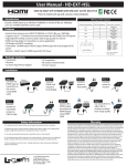
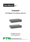
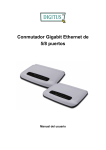
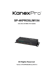
HDBaseT100 Meter - HDMI® Extender w/ Power over Ethernet HDMI/IR/RS232/Ethernet Twisted Pair Over Single Cable All Rights Reserved by KanexPro Version: HDBaseT Pro Extender_2014V2.0 HDBASE100POEL Extender NOTICE: Please read this user manual carefully before using this product. This manual is only for operation instruction only, not for any maintenance usage. The functions described in this version are updated till April 2014. Any changes of functions and parameters since then will be informed separately. Please refer to the dealers for the latest details. All rights reserved. No part of this publication may be copied or reproduced without permission.. Update History Version 1.0 2.0 Date 2014.02.22 2014.04.12 Update Content First version. Update version. HDBASE100POEL Extender Table of Contents 1. Introduction ..................................................................................................................1 1.1 Introduction to HDBaseT Pro Extender .............................................................. 1 1.2 Features ............................................................................................................. 1 1.3 Package Contents .............................................................................................. 1 2. Introduction of Product Appearance ............................................................................3 2.1 Product Appearance of HDMI Pro Transmitter................................................... 3 2.2 Product Appearance of HDMI Pro Receiver....................................................... 4 2.3 Twisted Pair Cable Connection .......................................................................... 5 3. System Connection .....................................................................................................5 3.1 Usage Precautions ............................................................................................. 5 3.2 System Diagram ................................................................................................. 6 3.3 Connection Procedure ........................................................................................ 6 3.4 System Applications ........................................................................................... 7 4. Specification ................................................................................................................7 5. Panel Drawing .............................................................................................................9 6. Troubleshooting & Maintenance ................................................................................10 7. Safety Operation Guide .............................................................................................11 8. After-sales Service.....................................................................................................12 HDBASE100POEL Extender 1. Introduction 1.1 Introduction to HDBaseT Pro Extender The KanexPro HDBASE100POEL is a transmitter - receiver set that enables you to routes ultra high – definition signals up to 330 feet (100 meters) over single CAT6 cable using HDBaseT Technology. This extender also features PoE – Power over Ethernet. The Extender has an HDMI loop for local monitor out while extending 330’ to the receiver side. This extender set is fully compliant with the latest HDCP specifications and supports EDID management for proper resolution output up to ultra HD 4K, 1080p/60 & 3D. With its Ethernet ports, the extender also supports Internet access to work in a LAN. 1.2 Features l l l l l l l l l l l l l l l l HDBaseT technology. High Bandwidth: 10.2Gps. Support CEC. Support 3D. Support PoC HDMI/IR/RS232 signal transmitted over single CAT5e/CAT6 twist pair. Max transmission distance is up to 90 meters for 1080P signals. Max transmission distance is up to 35 meters for 4K×2K signals. Support Ethernet expanding. HDTV Compatible, use HDMI 1.4a and HDCP compliant. Support 1080P, 1080i, 720P, 576P, 576i, 480P, and 480i. High quality output video signal with 24bit/36bit deep color. Bi-directional RS232 controls. Bi-directional IR controls. LED indicators show work status. Wall/table-mountable aluminum enclosure Note: Please use a CAT5e/6a cable with low impedance (Shielded twisted pair will be better and should be well grounded) for good transmission effect. 1.3 Package Contents Ø Ø Ø Ø Ø 1 x HDBASET Transmitter 1 x HDBASET Receiver 4 x Mounting ears (Separated from HD Transmitter and HD Receiver) 1 x Power adapter (DC 24V, 3A) 2 x IR Emitter (MYS-003B Φ3.5mm plug, not included, buy it separately) 1 HDBASE100POEL Extender Ø Ø Ø Ø 2 x IR receiver (TSMP1138 Φ3.5mm plug, not included, buy it separately) 2 x RS232 cable 8 x Screws (3*6mm) 1 x User manual Notes:Please confirm if the product and the accessories are all included, if not, please contact with the dealers. 2 HDBASE100POEL Extender 2. Introduction of Product Appearance 2.1 Product Appearance of HD Transmitter Figure 1 Interfaces of HDMI Pro Transmitter No. Name ① On Link In Power ② ETHERNET ③ HDBT OUT ④ HDMI IN ⑤ IR IN&OUT ⑥ RS232 ⑦ DC 24V Description ü On: Used to show the working status, blinks when in normal working state, turns off when stop working. ü Link: Twisted Pair Link status indicator. It will keep on when connection is successful. ü In: When connected with device, which supports HDCP and works normally, this LED will keep on. If the device does not support HDCP, the LED will blink. ü Power: Turns red and keep on when power on. Ethenet ports, when need to work in a local area network, one of these 4 ports (both the Ethernet ports of HD Transmitter and HD Receiver) should be used for internet access, and the others can be connected with computers. If they are well connected, the yellow LED indicators on the corresponding ports will keep blink and the green ones will keep on when working. To connect with the HDBT IN port of HDMI Pro Receiver by using a single CAT5e cable (90m length in max). HDMI input port, connect with an HDMI source device. ü IN: Connect with IR receiver, the IR signal received from this port can only send out in HD Receiver. ü OUT: Connect with IR Emitter, and the sending IR signal is received from HDMI Pro Receiver. Serial port, 3p captive screw connector, connect with the control terminal to control the controlled terminal, supports bi-directional RS232 control between the transmitter (HD Transmitter) and the receiver (HD Receiver). Connect with a DC 24V power adapter. (Not necessary if HDMI Pro Receiver connects with power adapter) 3 HDBASE100POEL Extender 2.2 Product Appearance of HD Receiver Figure 2 Interfaces of HDMI Pro Receiver No. Name ① Out Link On Power ② ETHERNET ③ HDBT IN ④ HDMI OUT ⑤ IR IN&OUT ⑥ RS232 ⑦ DC 24V Description ü Out: When connected with device, which supports HDCP and works normally, this LED will keep on. If the device does not support HDCP, the LED will blink. ü Link: Twisted Pair Link status indicator. It will keep on when connection is successful. ü On: Used to show the working status, blinks when in normal working state, turns off when stop working. ü Power: Turns red and keep on when power on. Ethenet ports, when need to work in a local area network, one of these 4 ports (both the Ethernet ports of HD Transmitter and HD Receiver) should be used for internet access, and the others can be connected with computers. If they are well connected, the yellow LED indicators on the corresponding ports will keep blink and the green ones will keep on when working. To connect with the HDBT OUT port of HD Transmitter by using a single CAT5e cable (90m length in max). HDMI output port, connect with an HDMI displaying device. ü IN: Connect with IR receiver, the IR signal received from this port can only send out in HDMI Pro Transmitter. ü OUT: Connect with IR Emitter, and the sending IR signal is received from HD Transmitter. Serial port, 3p captive screw connector, connects with the control terminal to control the controlled terminal, supports bi-directional RS232 control between the transmitter (HDMI Transmitter) and the receiver (HD Receiver). Connect with a DC 24V power adapter. (Not necessary if HD Transmitter connects with power adapter) 4 HDBASE100POEL Extender 2.3 Twisted Pair Cable Connection The twisted pair used in HDBASE100POEL Extender MUST be a straight-through cable. The connectors can be T568A or T568B, but both sides must be the same. TIA/EIA T568A TIA/EIA T568B Pin Cable color Pin 1 green white 1 orange white 2 green 2 orange 3 orange white 3 green white 4 blue 4 blue 5 blue white 5 blue white 6 orange 6 green 7 brown white 7 brown white 8 brown 8 brown 1st Ground 2nd Ground 3rd Group 4th Group 4--5 3--6 1--2 7--8 1st Ground 2nd Ground 3rd Group 4th Group Cable color 4--5 1--2 3--6 7--8 3. System Connection 3.1 Usage Precautions Please cut off the power of the HDMI source device and the output-displaying device before accessing with Extender, as it may damage to Extender. Ensure that all connections (including the power cord) are done before turning on the power to work with Extender. 5 HDBASE100POEL Extender 3.2 System Diagram Figure 3 System Diagram 3.3 Connection Procedure Step1. Connect HDMI source (such as DVD player) to HDMI IN port of the transmitter with HDMI cable. Step2. Connect HDBT OUT port of HD Transmitter and HDBT IN port of HD Receiver, with single CAT5e cable. Step3. Connect HDMI displayer (such as HDTV) to HDMI OUT port of HD Receiver with HDMI cable. Step4. Both HD Transmitter and HD Receiver have IR IN and OUT. When one model use for IR signal receiver, the other model must send out the IR signal. For example: When “IR IN” of HD Transmitter connects with an IR receiver, the IR Emitter must be connected to “IR OUT” of HD Receiver. Step5. To set as a LAN, one of the four ETHERNET ports of HD Transmitter and HD Receiver should be used for Internet access, and the others can be connected with computers. Step6. Connect the RS232 port of the computer and the RS232 port of HD Transmitter or HD Receiver (any one is able to work as the RS232 signal can be transmitted bi-directionally) by using a RS232 cable. Step7. Connect with DC24V power adaptor(s) (Any end of HD Transmitter and HD 6 HDBASE100POEL Extender Receiver connecting with power adapter is enough with its POC function). 3.4 System Applications As its good performance in control and transmission, HDBaseT Extender can be widely used in computer realm, monitoring, large screen displaying, conference system, education and bank securities institutions etc. 4. Specification Model Spec HDBASE100POET HDBASE100POER Input Input Signal 1xHDMI, 1xIR in, 1xRS232 Input Connector 1xHDMI female 1x3.5mm mini jack for IR in 1x3P captive connector 1xIR in, 1xHDBaseT, 1 x RS232 1x3.5mm mini jack for IR in 1xRJ-45 1x3P captive connector Video Signal HDMI1.4a HDMI1.4a Audio Digital audio, transmit through HDMI audio Digital audio, transmit through HDMI audio Output Output Output Connector 1xHDBaseT, 1xIR out, 1xRS232 1xRJ-45 1x3.5mm mini jack for IR out 1x3P captive connector Video signal HDMI1.4a Transmission Mode• HDBaseT 1xHDMI, 1xIR out, 1xRS232 1xHDMI female 1x3.5mm mini jack for IR out 1x3P captive connector HDMI1.4a Ethernet Port Connector 2xRJ45 Ethernet Transmission Speed 2xRJ45 Adaptive 10M/100M (max), full duplex or half duplex. General Resolution Range Transmission Distance Differential Phase Error 800x600 ~ 1920x1200 、3D、4K×2K Max distance 90m ±10° @ 135MHz_100M SNR >70dB@ 100MHz-100M Gain 0dB ~ 10dB@100MHz 7 HDBASE100POEL Extender Bandwidth 10.2Gbps Return Lost <-30dB@5KHz THD <0.005%@1KHz HDMI Standard Support HDMI1.4a and HDCP Min. ~Max. Level <0.3V ~ 1.45Vp-p Impedance 75Ω Temperature -20 ~ +70 Humidity 10% ~ 90% Power Consumption 10W Power Supply Input: 100VAC~240VAC, 50/60Hz; Output: 24VDC 1.25A Dimension (W*H*D) W 5.9" x H1.1" x D3.3" Net Weight 1.78 lbs. (0.8Kg) 8 HDBASE100POEL Extender 5. Panel Drawing Figure 4 Panel Drawing of HD Transmitter Figure 5 Panel Drawing of HD Receiver 9 HDBASE100POEL Extender 6. Troubleshooting & Maintenance 1) When there is a color losing or no video signal output, maybe the cables have already broken or haven’t been connected well. 2) When user cannot control the extender by computer through its COM port, please check the COM port number in the software, and make sure the COM port is in good condition and the communication protocol is correct. 3) If a device has connected with an ETHERNET port but the HDBaseT Extender can’t recognize it, please check whether its IP address is the same with another connected device. 4) When switching, there is no output image: l Check if there is any signal at the input. l Check if there is any signal at the output. We can check these by using an oscilloscope or a multimeter. If there is no signal input/output, maybe the input/output cables broken or the connectors loosen, please change for another cable. l Check if the output port number is the same with the controlled one. l If it is still the same after the above checking, maybe there is something wrong in the extender. Please send it to the dealer for repairing. 5) If the static becomes stronger when connecting the video connectors, it probably due to bad grounding, please check the grounding and make sure it connected well, otherwise it would damage the extender. 6) If the extender cannot be controlled through the RS232 port or by the IR remote, the unit may have already been broken. Please send it to the dealer for repairing. 10 HDBASE100POEL Extender 7. Safety Operation Guide In order to guarantee the reliable operation of the equipment’s and safety of the staff, please abide by the following proceeding in installation, using and maintenance: 1) The system must be earthed properly. Do not use two blades plugs and ensure the alternating power supply ranged from 100v to 240v and from 50Hz to 60Hz. 2) Do not put the device in a place of too hot or too cold. 3) As the power generating heat when running, the working environment should be maintained fine ventilation, in case of damage caused by overheat. 4) Cut off the general power switch in humid weather or left unused for long time. 5) Before following operation, ensure that the alternating current wire is pull out of the power supply: l Take off or reship any components of the equipment. l Take off or rejoin any pin or other link of the equipment. 6) As to non-professional or without permission, please DO NOT try to open the casing of the equipment, DO NOT repair it on your own, in case of accident or increasing the damage of the equipment. 7) DO NOT splash any chemical substance or liquid in the equipment or around. 11 HDBASE100POEL Extender 8. After-sales Service 1) If there appear some problems when running HDBaseT Pro Extender, please check and deal with the problems reference to this user manual. Any transport costs are borne by the users during the warranty. 2) You can email to our after-sales department or make a call, please tell us the following information about your cases. l Product version and name. l Detailed failure situations. l The formation of the cases. 3) We offer products for all three-year warranty, which starts from the first day you buy this product (The purchase invoice shall prevail). 4) Any problem is same with one of the following cases listed, we will not offer warranty service but offer for charge. l Beyond the warranty. l Damage due to incorrectly usage, keeping or repairing. l Damage due to device assembly operations by the maintenance company non-assigned. l No certificate or invoice as the proof of warranty. l The product model showed on the warranty card does not match with the model of the product for repairing or had been altered. l Damage caused by force majeure. Remarks: For any questions or problems, please try to get help from your local dealer. 12 9. Warranty KanexPro ® warrants that (a) its products (the “Product”) will perform greatly in agreement with the accompanying written materials for a period of 3 years from the date of receipt and (b) that the product will be free from defects in materials and workmanship under normal use and service for a period of 3 years. B. CUSTOMER REMEDIES KanexPro’s entire liability and Customer’s exclusive remedy shall be, at KanexPro option, either return of the price paid for the product, or repair or replacement of the Product that does not meet this Limited Warranty and which is returned to KanexPro with a copy of customers’ receipt. This Limited Warranty is void if failure of the Product has resulted from accident, abuse, or misapplication. Any replacement Product will be warranted for the remainder of the original warranty period or 90 days whichever is longer. C. NO OTHER WARRANTIES TO THE MAXIMUM EXTENT PERMITTED BY APPLICABLE LAW, KANEX DISCLAIMS ALL OTHER WARRANTIES, EITHER EXPRESS OR IMPLIED, INCLUDING, BUT NOT LIMITED TO IMPLIED WARRANTIES OF MERCHANTABILITY AND FITNESS FOR A PARTICULAR PURPOSE, WITH REGARD TO THE PRODUCT AND ANY RELATED WRITTEN MATERIALS. THIS LIMITED WARRANTY GIVES CUSTOMERS SPECIFIC LEGAL RIGHTS. CUSTOMERS MAY HAVE OTHER RIGHTS DEPENDING ON THE JURISDICTION. D. NO LIABILITY FOR DAMAGES TO THE MAXIMUM EXTENT PERMITTED BY APPLICABLE LAW, IN NO EVENT SHALL KANEX BE LIABLE FOR ANY DAMAGES WHATSOEVER (INCLUDING WITHOUT LIMITATION, SPECIAL, INCIDENTAL, CONSEQUENTIAL, OR INDIRECT DAMAGES FOR PERSONAL INJURY, LOSS OF BUSINESS PROFITS, BUSINESS INTERRRUPTION, LOSS OF BUSINESS INFORMATION, OR ANY OTHER PECUNIARY LOSS) ARISING OUT OF THE USE OF OR INABILITY TO USE THIS PRODUCT, EVEN IF KANEX HAS BEEN ADVISED OF THE POSSIBILITY OF SUCH DAMAGES. Brea, California KanexPro.com MPN: HDBASE100POEL HDMI & HDBaseT are trademarks or registered trademarks of HDMI Licensing LLC & HDBaseT alliance in the United States and other countries. KanexPro is a registered trademark of Apogee Inc., registered in the U.S.