1
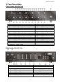
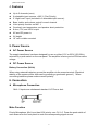
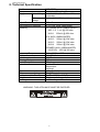
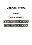
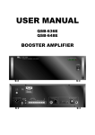
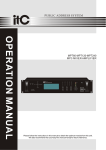
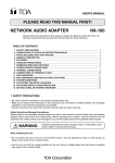
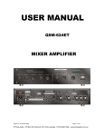
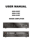
USER MANUAL
QSM-6505A
Distribution Mixer Amplifier
QSM-6505A Manual
1. Security Precautions
◎
◎
Carefully to READ the instruction in this manual before use.
Certainly to OBSERVE the INSTRUCTION in this manual regard convention of safety
symbols and messages.
◎
Please KEEP this user MANUAL nearby for anytime reference.
Safety symbol and Message Conventions
Below-described safety symbol and messages are to prevent bodily injury and property
damage. Before operating the amplifier, read this manual first so you completely knowing
the potential safety hazard and understanding the meaning of the safety symbols and
messages.
Indicates a potentially hazardous situation, which, if
WARNING
mishandled, could result in death or serious body
injury, and/or property damage.
CAUTION
Indicates a potentially hazardous situation, which, if
mishandled, could result in moderate or minor body
injury, and/or property damage.
WARNING
PANEL DESCRIPTION
■ When Installing the Amplifier
DO NOT installing or mounting the amplifier in unstable locations, such as on the
rickety table or the slanted surface. It may result in the amplifier falling down
and causing body injury and/or property damage.
Be sure to ground to the safety ground (earth) terminal to avoid electric shock.
Never to ground to a gas pipe for tragic disaster may occur.
Use the amplifier only with the voltage specified on the amplifier. Using the voltage
higher than specified may cause fire or electric shock.
DO NOT cut, twist, damage, nor modify the power supply cord. In addition, avoid
using the power cord close to heaters, and don’t place heavy object, including
the amplifier itself, on the power cord, for it may cause fire or electric shock.
DO NOT expose the amplifier to rain or the environment where it may be splashed by
water or other liquids, for doing so, it may cause fire or electric shock.
2
QSM-6505A Manual
When using the Amplifier
When found following irregular situation during amplifier is in use, immediately switch off
the power, disconnect the power supply plug from the AC outlet. Don’t try to operate
the amplifier again.
Contact your local dealer to check the amplifier.
The amplifier falls.
Amplifier is malfunction.
Water or any metallic object gets into the amplifier.
The smoke or strange smell coming from the amplifier.
The power supply cord is damaged, such as exposure of the core, disconnection etc..
DO NOT put cups, bowls, or other containers with liquid or metallic object in it on the
top of the amplifier. If they spill accidentally into the amplifier, it may result in
fire or electric shock.
DO NOT touch the power supply plug during thundering and lightning, for it may result
in electric shock.
DO NOT insert or drop the metallic objects or flammable materials into the ventilation
slots of the amplifier, for it may result in fire or electric shock.
DO NOT open nor remove the amplifier cover to prevent fire or electric shock, for there
are high voltage components inside the amplifier.
CAUTION
PANEL DESCRIPTION
■ When Installing the Amplifier
DO NOT remove nor plug in the power supply plug with wet hands, for it may cause
electric shock.
When unplug the power supply cord, be sure to grasp the power supply plug. DO
NOT pull on the cord itself. Operating the amplifier with damaged power
supply cord may cause fire or electric shock.
Avoid installing the amplifier in humid or dusty places, the area exposed to the direct
sunlight, locations generating smoke or steam, or the spot near the heaters.
It may result in fire or electric shock.
When moving the amplifier, be sure to remove its power supply cord from the wall
outlet. Moving the amplifier with the power cord connected to the outlet may
cause damage to the power cord, and resulting in fire or electric shock.
When removing the power cord, be sure to grasp its plug to pull.
DO NOT block the ventilation slots of the amplifier chassis.
temperature rising and result in fire.
-3-
It will cause the
QSM-6505A Manual
■ When Using the Amplifier
Make sure that the volume control is turned to minimum position before power is
switched on. Loud sound produced at high volume when power is switched
on may impair hearing.
DO NOT place heavy objects on the amplifier, for it may cause it fall and may result in
body injury and/or property damage. Besides, the object itself may cause
damaged or body injury.
DO NOT operate the amplifier for the extended period of time with the sound distorting.
It is an indication of malfunction, which can cause heat and result in fire.
Switch the power off, and unplug the power supply plug from the AC outlet for safety
purposes, when cleaning or leaving the amplifier unused for 7 days or more.
Fire or electric shock may occur.
If the dust accumulates on the power supply plug or in the wall AC outlet, fire may
result in. Clean it periodically. In addition, make sure the plug is inserted in
the wall outlet securely.
Contact your local dealer to clean the dust, it the dust has accumulated in the amplifier
for a long period of time. Dust accumulation may result in fire or damage.
2. Description
QSM-6505A is the mixer amplifier designed for up to 5 channels (zones) application.
Each channel output is 50W RMS. And each one has its own bass, treble, and level
(volume) control. There are 6 input sources: Aux 1 ~ 4, and 2 “High Level” inputs. “High
Level” input is for the connection from the output of other amplifier, no matter it is 8 ohm,
70V, or 100V.
The front MIC. 1 input has the voice priority function with level control.
one push switch to select to mute its own signal source or not.
Each channel has
To ensure the amplifier safety, it has speaker short, over temperature, and overload
protection.
The output connection is 8 ohm, 70V, and 100V screw terminal.
It accepts AC 115V/230V 50/60 Hz and DC 24V input.
QSM-6505A is the ideal mixer amplifier for multi-zone with multi sources.
4
QSM-6505A Manual
3. Panel Description
FRONT PANEL DESCRIPTION
1. MIC. 1 Input
2. MIC. 1 Volume Control
3. Channel 1 Mute Priority Switch
4. Channel 1 Input Source Selection Switch
5. Channel 2 Mute Priority Switch
6. Channel 2 Input Source Selection Switch
7. Channel 3 Mute Priority Switch
8. Channel 3 Input Source Selection Switch
9. Channel 4 Mute Priority Switch
10. Channel 4 Input Source Selection Switch
11. Channel 5 Mute Priority Switch
12. Channel 5 Input Source Selection Switch
13. Power Switch
14. Channel 1 Bass Control
15. Channel 1 Treble Control
16. Channel 1 Volume Control
17. Channel 2 Bass Control
18. Channel 2 Treble Control
19. Channel 2 Volume Control
20. Channel 3 Bass Control
21. Channel 3 Treble Control
22. Channel 3 Volume Control
23. Channel 4 Bass Control
24. Channel 4 Treble Control
25. Channel 4 Volume Control
26. Channel 5 Bass Control
27. Channel 5 Treble Control
28. Channel 5 Volume Control
29. Power Indicator - LED
REAR PANEL DESCRIPTION
1. AC Power Input Socket
2. Earth Ground Connection Screw
3. AC Voltage (115V/230V) Selection Switch
4. Channel 5 Output Terminal
5. Channel 4 Output Terminal
6. Channel 3 Output Terminal
7. Channel 2 Output Terminal
-5-
8. Channel 1 Output Terminal
9. “High Level” Input Terminal
10. Aux 2 ~ 4 Input (RCA Jack)
11. Aux 1/MIC 2 Selection Switch
12. Aux 1/MIC 2 Input
13. AC Fuse
14. DC Power Supply Terminals
QSM-6505A Manual
4. Features
Up to 5 channels (zone)
6 selectable input sources + MIC 1 (First Priority)
2 “High Level” input (included in 6 selectable input source).
Bass, treble, and volume control for each channel
Voice priority function on MIC. 1
Overload, over temperature, and speaker short protection.
8 ohm, 70V, and 100V output
AC and DC power in
2U height
19” rack or table mounted
5. Power Source
AC Power Source
The supply transformer has been designed for use on either 115V or 230V, (50-60Hz),
selected by a push switch on the rear panel. The amplifier is factory set at 230Vac mains
voltage.
DC Power Source
Battery Connection (24Vdc)
When using external batteries, ground the amplifier via the screw terminal. (Electrical
stability of the system will be improved by providing a good earth ground.) When
connecting batteries please ensure correct polarity.
6. Connection
Microphone Connection
Mic1~2 inputs are unbalanced standard 1/4” Phone Jack.
Mute Function
Priority Microphone, Mic1 input has VOX priority over CH 1~5. Press the push switch of
each channel on the front panel to mute the corresponding signal source.
6
QSM-6505A Manual
Aux Connection (Input)
The equipment provides 4 auxiliary input which may be used for connecting other signal
sources such as a Radio Tuner, CD or Cassette player. A slide switch is located near by
AUX1/MIC 2 on the rear panel for selection of Mic2 or Aux1. Aux 2 ~ 4 inputs are a dual
RCA jack and has a stereo to mono converter for each channel
PIN
SLEEVE
RCA plug connector
High Level Input Connection
The “High Level” terminal is for connecting the signal sources from other amplifier output,
which is normally connected to the speaker.
Output Connection
There are 5 output terminals on the rear panel. Each terminal has 3 speaker outputs: 8
ohm, 70V and 100V. Use only one of these outputs for connection.
7. Operation
After all connections are completed, turn the Input Source Selection Switch of each channel
to set on the corresponding position for the signal source. If necessary, turn the bass, treble,
and volume control to what you desire.
Before using the microphone 1 on the front panel to broadcast, make sure the level (volume)
control of MIC 1 is at proper position (not at maximum position). Set the push switch of
each channel to control the mute function of its own channel signal source. Switch-down is
to mute signal source, only the voice from MIC 1 can be heard, while switch-up does not
mute signal source, both voice from MIC 1 and channel signal can be heard. If necessary
to adjust the volume further, turn the level control of MIC 1 and/or of Channel 1 ~ 5.
-7-
QSM-6505A Manual
8. Technical Specification
Model
Type
Supply
QSM-6505A
Distribution Mixer Amplifier
Mains Voltage AC 115V/ 230V, 50 / 60Hz ± 10%
Switchable
Battery
DC 24V (MAX 10% deviation)
Voltage
Output Power:
50W x 5
Total Harmonic Distortion
<= 0.1% @ 1KHz, rated power
Sensitivity
1/4" PHONE JACK (UNBALANCED)
MIC 1~2 1 mV @ 600 ohm
AUX 1 200mV @ 20K ohm
RCA JACK (UNBALANCED)
AUX 2 200mV @ 20K ohm
AUX 3 200mV @ 20K ohm
AUX 4 200mV @ 20K ohm
SPEAKER JACK (UNBALANCED)
HI LEVEL 100V @ 300 ohm
Frequency Response
50Hz ~ 15KHz ± 3dB
Output
100V, 70V, 8 ohm; screw terminal
Signal to noise ratio
< 70dB
Damping Factor
>200
Voice Priority Mute
MIC. 1
Protection
Speaker Short
Temperature
Overload
AC power consumption
640W @ rated power
DC power consumption
15A @ rated power
Dimensions ( H x W x D )mm 88 (H) x 425(W) x 345 (D) mm
Weight
15 kgs
Mounting
Free standing or 19” rack
WARNING: THIS APPLIANCE MUST BE EARTHED
8