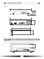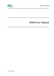
1
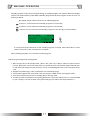
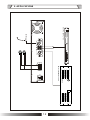
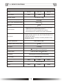
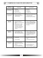
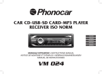
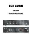
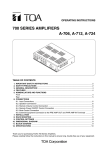
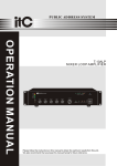
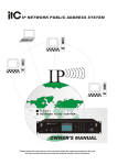
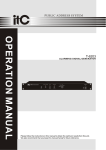
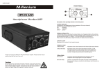
PUBLIC ADDRESS SYSTEM
OPERATION MANUAL
MPT60-MPT120-MPT240
MP3 MIXER AMPLIFIER
UP
MP3
MPT60
MP3 MIXER AMPLIFIER
1
2
3
4
5
6
7
8
9
0/--
PROT
POWER
10
SWIFT
RIGHT
LEFT
8
6
4
2
MP3
AUX 1
BASS
MASTER
DOWN
4
5
6
3
0
10
MIC
SD CARD
0
10
AUX 2
7
- dB +
TREBLE
2
8
1
0
10
0
10
- dB +
9
0
ON
OFF
10
Please follow the instructions in this manual to obtain the optimum results from this unit.
We also recommend that you keep this manual handy for future reference.
TABLE OF CONTENTS
1. SAFETY PRECAUTIONS ...................................................................3
2. FEATURES .......................................................................................5
3. FRONT AND REAR PANEL FUNCTION ..............................................6
4. MACHINE OPERATION ....................................................................7
5. APPLICATIONS .............................................................................. 12
6. SPECIFICATIONS ...........................................................................13
7. COMMON FAULT ANALYSIS AND ELIMINATION................................14
8. DIMENSIONAL DIAGRAM ...............................................................15
2
Be sure to read the instructions in this section carefully before use.
Make sure to observe the instructions in this manual as the conventions of safety symbols and messages
regarded as very important precautions are included.
We also recommend you keep this instruction manual handy for future reference.
Safety Symbol and Message Conventions
Safety symbols and messages described below are used in this manual to prevent bodily injury and property
damage which could result from mishandling. Before operating your product, read this manual first and
understand the safety symbols and messages so you are thoroughly aware of the potential safety
Indicates a potentially hazardous situation which, if mishandled, could
result in death or serious personal injury.
Indicates a potentially hazardous situation which, if mishandled, could
result in moderate or minor personal injury, and/or property damage.
When the Unit is in Use
When Installing the Unit
Should the following irregularity be found during
use, immediately switch off the power, disconnect
the power supply plug from the AC outlet and
contact your nearest ITC dealer. Make no
further attempt to operate the unit in this condition
as this may cause fire or electric shock.
If you detect smoke or a strange smell coming
from the unit.
If water or any metallic object gets into the unit
If the unit falls, or the unit case breaks
If the power supply cord is damaged (exposure of
the core, disconnection, etc.)
If it is malfunctioning (no tone sounds.)
Do not expose the unit to rain or an environment
where it may be splashed by water or other liquids,
as doing so may result in fire or electric shock.
Use the unit only with the voltage specified on the
unit. Using a voltage higher than that which is
specified may result in fire or electric shock.
Do not cut, kink, otherwise damage nor modify the
power supply cord. In addition, avoid using the
power cord in close proximity to heaters, and never
place heavy objects -- including the unit itself -- on
the power cord, as doing so may result in fire or
electric shock.
To prevent a fire or electric shock, never open nor
remove the unit case as there are high voltage
components inside the unit. Refer all servicing to
your nearest ITC dealer.
Be sure to replace the unit's terminal cover after
connection completion. Because high voltage is
applied to the speaker terminals, never touch these
terminals to avoid electric shock.
Do not place cups, bowls, or other containers of
liquid or metallic objects on top of the unit. If they
accidentally spill into the unit, this may cause a fire
or electric shock.
Be sure to ground to the safety ground (earth)
terminal to avoid electric shock. Never ground to a
gas pipe as a catastrophic disaster may result.
Do not insert nor drop metallic objects or
flammable materials in the ventilation slots of the
unit's cover, as this may result in fire or electric
shock.
Avoid installing or mounting the unit in unstable
locations, such as on a rickety table or a slanted
surface. Doing so may result in the unit falling
down, causing personal injury and/or property
damage.
3
When the Unit is in Use
When Installing the Unit
Do not place heavy objects on the unit as this may
cause it to fall or break which may result in
personal injury and/or property damage. In
addition, the object itself may fall off and cause
injury and/or damage.
Never plug in nor remove the power supply plug
with wet hands, as doing so may cause electric
shock.
When unplugging the power supply cord, be sure
to grasp the power supply plug; never pull on the
cord itself. Operating the unit with a damaged
power supply cord may cause a fire or electric
shock.
Make sure that the volume control is set to
minimum position before power is switched on.
Loud noise produced at high volume when power is
switched on can impair hearing.
When moving the unit, be sure to remove its power
supply cord from the wall outlet. Moving the unit
with the power cord connected to the outlet may
cause damage to the power cord, resulting in fire or
electric shock. When removing the power cord, be
sure to hold its plug to pull.
Do not operate the unit for an extended period of
time with the sound distorting. This is an indication
of a malfunction, which in turn can cause heat to
generate and result in a fire.
Contact your ITC dealer as to the cleaning.
If dust is allowed to accumulate in the unit over
a long period of time, a fire or damage to the
unit may result.
Do not block the ventilation slots in the unit's cover.
Doing so may cause heat to build up inside the unit
and result in fire.
If dust accumulates on the power supply plug or in
the wall AC outlet, a fire may result. Clean it
periodically. In addition, insert the plug in the wall
outlet securely.
Avoid installing the unit in humid or dusty locations,
in locations exposed to the direct sunlight, near the
heaters, or in locations generating sooty smoke or
steam as doing otherwise may result in fire or
electric shock.
Switch off the power, and unplug the power supply
plug from the AC outlet for safety purposes when
cleaning or leaving the unit unused for 10 days or
more. Doing otherwise may cause a fire or electric
shock.
An all-pole mains switch with a contact separation of at least 3 mm in each pole shall be incorporated in
the electrical installation of the building.
Due to product upgrades, while some of the features and specification in the user manual does not
match the actual functions, sorry for any inconvenience and thanks for your kind understanding!
4
2. FEATURES
1. Mixer amplifier built-in MP3 and weekly times
2. Amplifier power output from 60W,120W to 240W
3. Rack mount type in 2U height
4. MP3 input by SD card in front panel
5. 1 MIC input by combo type
6. 2 AUX input by RCA type
7. Balanced line output
8. Speaker output:70V,100V and 4-16ohms
9. Extensive protection include high temp, overload and short circuit
10. MIC input with priority over other inputs, and mute level control is supplied
11. Bass/treble tone control and volume control for MP3,MIC,AUX1-2 and master volume control
12. Play, all play, circle, repeat, random play modes
13. Weekly program over time, sound selection & play mode
14. 4 master programs and 1 spare program
15. 0 to 9 ten sound number direct selection buttons
16. MP3, swift, up down, left, right and functional buttons
17. 5 level output indication, protection and power indicator
5
3. FRONT AND REAR PANEL FUNCTION
3.1 FRONT PANEL
14
16 15
13
11
12
UP
1
2
3
4
5
6
7
8
9
0/--
10 9
PROT
MP3
POWER
10
SWIFT
RIGHT
LEFT
8
6
4
2
MP3
AUX 1
BASS
MASTER
DOWN
5
4
6
3
0
0
10
MIC
SD CARD
7
- dB +
10
AUX 2
TREBLE
2
0
1
0
10
- dB +
10
2 3 4
5 6
ON
8
1
OFF
9
0
10
7
8
3.2 REAR PANEL
PRE OUTPUT
AUX2 IN
AUX1 IN
MIC IN
PUSH
COM 4-16
70V 100V
MASTER
V.O.
2
1
3
TIME
17
18
19
20
21
22
23
24
1. SD card slot
12.Working status screen
2. MP3 volume adjustment
13.Up/Down/Left/Right choose button
3. MIC input volume adjustment
14.Confirm Key
4. AUX1/AUX2 input volume adjustment
15.Swift
5. BASS volume control
16.MP3 Volume Control key
6. Treble volume control
17.Power input
7. Mater volume control all the input level
18.Output terminal, connect with speakers
8. Power switch
19.Master
Press up means power on
20.Pre out put
Press down means power off
21.Line input
9. Level indicator
22.Mic input
10.Port
23.Mute time adjust
24.Fan
Protection indicator
11.Numeric key
6
4. MACHINE OPERATION
1.Home screen illustration
2005/11/08/2
09
Next Tue
01
02
45
02
03
MP3 ERR
First line: System date, day, and time display
Eg. 2005/ 11/ 08 /2
09:
45:
02
Year Month Date Day Hour Minute Second
Second line: Current date next step program time and control content
Eg. Next: Tuesday 11: 02:03
Third line: Current system status
MP3 status:
1. MP3
08
02
03
20
Status current song number hour minute second
2. MP3
STOP
MP3
STOP
3. MP3
10
Song total number
ERR
Without insert SD card storage devices or cannot be distinguished
4. Mp3
WAITING
Controller is reading MP3 total songs.
2. MP3 OPERATION
UP
Push MP3 key to operate when it is on the main screen menu, then push
LEFT
RIGHT
To select
DOWN
2005/11/08/2
MP3
MP3 STOP-10
09
45
02
MP3
Player all
2:
music format or program, Push
3:
4:
ENTER
key for MP3 format.
Caution
1 On MP3 screen. Push MP3 key to cancel the prog ram insert.
2 On MP3 screen, the system will cancel the insert function without any Operation within 5 seconds.
7
MACHINE OPERATION
3. System main menu operation
ENTER
When display home screen, press
key
key to enter system main menu: Press
LEFT
RIGHT
System Setting
ENTER
Choose corresponding menu options, press
key again, enter to corres ponding submenu
ENTER
interface, if need to exit menu, then press
key on Exit icon.
UP
2005/ 02/10
ENTER
Mon
05:12:02
LEFT
RIGHT
Cancel
OK
DOWN
Confirm current modification,please press OK,exit Time setup menu,return to system main menu.
Cancel current modification, press Cancel, exit Time setup menu, return to system main menu.
4. System setup
Press Enter key in system main menu System Setup icon, show as below
Week
procedure
MON
TUE
WED
N/A
2
N/A
THU
FRI
SAT
SUN
2
4
1
3
Cancel
OK
Program corresponding bar 1,2,3,4,5 stand for program number 1, 2, 3, 4, 5.Number 1,2,3,4 is regular
program,No.5 is standby program.Automatic run program number setup:
UP
Week
procedure
MON
TUE
WED
THU
FRI
SAT
SUN
N/A
2
2
N/A
4
1
3
OK
Cancel
LEFT
RIGHT
DOWN
Confirm current modification, please press OK key,exit system setup menu,return to system main
menu.Cancel current modification, press Cancel key, exit system setup menu,return to system main
menu.
8
MACHINE OPERATION
5. Time setup
In system main menu Time setup icon press Enter key, show as below
2005/10/03
Mod
ENTER
11:24:04
OK
Cancel
UP
Enter
LEFT
RIGHT
to adjust year, month, day, date, hour, minute, second.
DOWN
6. Edit program
Press Enter in Edit program in system main menu. If there is no program content,it will show as below:
Procedure
Add
1
The-Step
Cancel
-- : --: --
Exit
Cancel call
If there is content in program, it will show as below:
00 : 00:00
Procedure 1 The 001 Step
1
Add
-- 2
Cancel
--
3
--
4
Cancel call
--
UP
LEFT
Exit
RIGHT
DOWN
In current program, press ENTER at ADD icon position, then it will be the below diagram.
Procedure 1 The 001 Step
MP3
Add
Player all
Cancel
00 : 00:00
01 Song Songs select
Cancel call
Exit
Choose the corresponding content to edit the relative specifications,choose ADD,it can edit
next program and specification.
Browse program
Choose corresponding program number, press Down to adjust program steps, then every stpes
in the program can be browsed.
9
MACHINE OPERATION
Modify program
Choose corresponding program number,adjust program steps to find out the program which needs
to be modified, then users can modify the correspondingcontents in this step, such as time, function,
etc.
Add program:
Choose corresponding program number, press Add key, then it can add a new program. Users
follow the same method as above to modify the corresponding contents.
Delete single step program
Choose corresponding program number, adjust program steps to find out the programs which
need to be deleted. Choose Delete key, then it can delete current step displayed.
Delete all programs
Choose corresponding program number,enter Delete All, it can delete all programs.
Exit
Press Exit, then it exit Edit program menu, return to main menu.
Note:
1. When it shows which step, it just as a prompt function, when add , modify program, it will
adjust automatically, and will show steps inconsistent with actual situation, which is normal.
When enter into Edit program interface,the steps will automatically adjust.
2. When it shows the below interface,it means the program reach 200 steps,it cannot be added
program anymore, or it means all the program totally reach 512 steps, there is no storage
space.
Procedure1 The200 Step 01 : 10 : 05
Procedure1 The130 Step 01 : 10 :05
Reach max steps
Add
Cancel
Cancel all
Insufficient storage space
Exit
Add
Cancel
Cancel all
Exit
Standby program run:
Standby program aims at fixed time, but runs when the run date is not confirmed.
For example:When it is rainy or snowy date, the rest time in school is different as usual, such as get
up time, morning exercises an d class-break exercise, etc. Even though the rest time is the same for
rainy or snowy date, the date is not confirmed, so this is the time to start standby program.
Standby program can be set to run in the current day, or predictable to run in th e second day, or to
run two days continuously (current day and the second day).
10
MACHINE OPERATION
Standby program control key is used for setting up standby program run method. When the display
screen is at main interface, press SWIFT,standby program will be next program, there are four run
method as below:
No display, which means it does not run standby program
It shows 1, which means the standby program in current day
It shows 2, which means the standby program in second day
It shows 12, which means the standby program in current day and second day.
SWIFT
Next Tue
8
MP3 STOP-10
It is only the first time effective for the standby program run setup, after setup date, if users
need to continue it, then it needs to be set again.
Note: Standby program run is the fifth number program.
7.MP3 songs storage and management
1. MP3 songs store in SD storage card . (Note: SD card only support 200 mA output electric
current, please do not connect with large current SD devices, such as SD card notebook disc,
or with SD card charge function devices, or else, it will damage device,or SD card work abnor
-mal.
2. Support most 99 songs, it will not deal with the exceeding songs.
3. File system support FAT and FAT32. FAT max support 16 GB, FT32 max support 64TB.
4. It is not permitted to set zones or multiple files in storage card.
5. In order to make sure MP3 work regularly,please do not use the SD card if it is not assembled
by our company. Or else, if there is any abnormal play, we will not be responsible for it.
11
12
ON
OFF
2
1
3
0
4
5
10
6
VOLUME
9
7
8
POWER SIGNAL CLIP PROT OL
HEAVY BASS AMPLIFIER
USE ONLY WITHA 250V FUSE
COM 4-16
70V 100V
EJECT
PLAY
STOP
USB
PLAY
MODE
PREV
SD
NEXT
MASTER
USB/CD
MUTE
CD PLAYER
IR STATUS
PRE OUTPUT
AUX2 IN
AUX1 IN
2
REMOTE
3
PUSH
MIC IN
1
1
2
3
4
AUTO/
AM/FM ST/MON MEM MANUAL
AM/FM DTS TUNER
5
UP
6
DOWN
POWER
CD + TUNER PLAYER
TIME
V.O.
MIC
5. APPLICATIONS
6. SPECIFICATIONS
Model
Power Output
MPT60
MPT120
60W
120W
Speaker Outputs
5mV/2K
AUX1-2 Input Sensitivity/Impedance
350mV/10K
S/N Ratio
MP3 format
66dB
Support both FAT16 and FAT32,do not support file format
supports up to 4G-1 bytes as the file size.
The maximum number of playable files is 65534.
Sorts and plays up to 100 files in the order of UNICODE.
Support MPEG audio1,2 and 2.5. Support layer 1,2 and 3.
Support sample rates 8K, 16K, 32K,11.025K,22.05K,44.1K,
12K,24K and 48KHz.
Supports bit rate 8 to 320 kbps and VBR (variable bit rate).
Except free format.
Frequency Response
50Hz-18KHz(-3dB)
Tone(Bass:100Hz,Treble:10KHz)
10dB
1V/600
Pre Output
0.5% at 1KHz, 1/3 rated power
THD
Total 512 Steps,1day
Program Steps
Time Mode
~220-240V 50Hz
100W
Dimensions
Weght
200 Steps
24 hours(hour-minutes-seconds)weekly
Power Supply
Power Consumption
240W
70V,100V & 4~16
MIC Input Sensitivity/Impedace
SD File system
MPT240
180W
350W
484X358X88 mm
9.0Kg
13
10.2Kg
12.9Kg
7. COMMON FAULT ANALYSIS AND ELIMINATION
FAULT
PHENOMENA
DIAGNOSE
EXCLUSION
NO DISPLAY ON
THE SCREEN
1
2
3
4
Power off
Power switch
Fuse burned
High or low temp
1
2
3
4
KEY OUT OF
FUNCTION
1
2
Push on wrong key
The other keys are on
pressed state
1
NO USB
DISPLAY
1
2
USB out of function
Improper connection with
USB
USB output more than
200mA, such as USB
works with notebook
computer, rechargeable
USB or with special
symbol
1
2
3
Delete not Mp3 format file
Change the hidden setting
AUDIO
Remove Mp3 of other files
except the storage root
directory
3
Power on
Switch on
Change AC
Change temp
Enter the operation screen
to operate again
2 Release the pressed key
NO MP3
DISPLAY
1
2
3
Improper Mp3 format
Mp3 with hidden setting
Over number of Mp3 sound
1
2
3
Delete not Mp3 format file
Change the hidden setting
Remove Mp3 of other files
except the storage root
directory
UNSTABLE MP3
BROADCASTING
1
Low Volume
1
2
Errors in BGM
2
Adjust the volume of MP3
itself
Delete all the other files
NO AUDIO
OUTPUT
1 Improper connection
2 No output from the audio
1 Cha nge the proper connection
source
3 No power on amplifier
4 Volume closed of amplifier
2 Check the audio source
3 Power on amplifier
4 Open the volume of amplifier
14
8. DIMENSIONAL DIAGRAM
UNIT :mm
484
UP
1
2
3
4
5
6
7
8
9
0/--
PROT
POWER
10
SWIFT
RIGHT
LEFT
8
6
88
4
2
MP3
AUX 1
BASS
MASTER
DOWN
5
4
6
3
0
0
10
MIC
SD CARD
7
- dB +
10
AUX 2
TREBLE
2
0
10
OFF
9
0
- dB +
10
ON
8
1
0
90
MP3
10
PRE OUTPUT
AUX2 IN
AUX1 IN
84
436
MIC IN
PUSH
COM 4-16
70V 100V
MASTER
V.O.
2
1
3
USE ONLY WITHA 250V FUSE
TIME
367
350
84
25
6
UP
1
2
3
4
5
6
7
8
9
0/--
Over 100
UNIT :mm
PROT
MP3
POWER
10
SWIFT
RIGHT
LEFT
8
6
4
2
MP3
AUX 1
BASS
MASTER
DOWN
4
5
6
3
0
10
MIC
SD CARD
0
10
AUX 2
7
- dB +
TREBLE
2
8
1
0
Over 100
10
0
10
- dB +
9
0
ON
OFF
10
Over 100
15
PUBLIC ADDRESS SYSTEM
VersionV0.3