1
INVERTER
INVERTER
PRE-OPERATION INSTRUCTIONS
1
INSTALLATION
2
WIRING
3
INVERTER SETTING
4
FUNCTION OVERVIEW
5
I/O SIGNAL LIST
6
DETAILS OF INPUT AND OUTPUT SIGNALS
7
PROGRAMMING EXAMPLES
8
HOW TO CHECK FOR ERROR USING THE LEDS
9
Plug-in option
INVERTER
FR-A7NC E kit
IB(NA)-0600340ENG-C(1106) MDOC
Printed in Japan
Specifications subject to change without notice.
INSTRUCTION MANUAL
HEAD OFFICE: TOKYO BUILDING 2-7-3, MARUNOUCHI, CHIYODA-KU, TOKYO 100-8310, JAPAN
C
FR-A7NC E kit
INSTRUCTION MANUAL
communication function
Thank you for choosing this Mitsubishi Inverter plug-in option.
This Instruction Manual gives handling information and
precautions for use of this equipment. Incorrect handling might
cause an unexpected fault. Before using the equipment, please
read this manual carefully to use the equipment to its optimum.
Please forward this manual to the end user.
This section is specifically about
safety matters
Do not attempt to install, operate, maintain or inspect this
product until you have read through this Instruction Manual and
appended documents carefully and can use the equipment
correctly. Do not use this product until you have a full
knowledge of the equipment, safety information and
instructions.
In this Instruction Manual, the safety instruction levels are
classified into "WARNING" and "CAUTION".
WARNING
CAUTION
Incorrect
handling
may
cause
hazardous conditions, resulting in
death or severe injury.
Incorrect
handling
may
cause
hazardous conditions, resulting in
medium or slight injury, or may cause
only material damage.
CAUTION level may even lead to a serious
The
consequence according to conditions. Both instruction levels
must be followed because these are important to personal
safety.
SAFETY INSTRUCTIONS
1. Electric Shock Prevention
WARNING
• While power is ON or when the inverter is running, do not
open the front cover. You may get an electric shock.
• Do not run the inverter with the front cover or wiring cover
removed. Otherwise, you may access the exposed highvoltage terminals and charging part and get an electric shock.
• Even if power is OFF, do not remove the front cover except for
wiring or periodic inspection. You may accidentally touch the
charged inverter circuits and get an electric shock.
• Before wiring or inspection, power must be switched OFF. To
confirm that, LED indication of the operation panel must be
checked. (It must be OFF.) Any person who is involved in
wiring or inspection shall wait for at least 10 minutes after the
power supply has been switched OFF and check that there
are no residual voltage using a tester or the like. The
capacitor is charged with high voltage for some time after
power OFF, and it is dangerous.
• Any person who is involved in wiring or inspection of this
equipment shall be fully competent to do the work.
• The plug-in option must be installed before wiring. Otherwise,
you may get an electric shock or be injured.
• Do not touch the plug-in option or handle the cables with wet
hands. Otherwise you may get an electric shock.
• Do not subject the cables to scratches, excessive stress,
heavy loads or pinching. Otherwise you may get an electric
shock.
A-1
2. Injury Prevention
3) Usage
WARNING
CAUTION
• The voltage applied to each terminal must be the ones
specified in the Instruction Manual. Otherwise burst, damage,
etc. may occur.
• The cables must be connected to the correct terminals.
Otherwise burst, damage, etc. may occur.
• Polarity must be correct. Otherwise burst, damage, etc. may
occur.
• While power is ON or for some time after power-OFF, do not
touch the inverter as they will be extremely hot. Doing so can
cause burns.
3. Additional Instructions
Also the following points must be noted to prevent an accidental
failure, injury, electric shock, etc.
1) Transportation and mounting
• Do not modify the equipment.
• Do not perform parts removal which is not instructed in this
manual. Doing so may lead to fault or damage of the inverter.
CAUTION
• When parameter clear or all parameter clear is performed, the
required parameters must be set again before starting operations
because all parameters return to the initial value.
• For prevention of damage due to static electricity, nearby
metal must be touched before touching this product to
eliminate static electricity from your body.
4) Maintenance, inspection and parts replacement
CAUTION
CAUTION
• Do not install or operate the plug-in option if it is damaged or
has parts missing.
• Do not stand or rest heavy objects on the product.
• The mounting orientation must be correct.
• Foreign conductive objects must be prevented from entering
the inverter. That includes screws and metal fragments or
other flammable substances such as oil.
2) Trial run
CAUTION
• Before starting operation, each parameter must be confirmed
and adjusted. A failure to do so may cause some machines to
make unexpected motions.
A-2
• Do not test the equipment with a megger (measure insulation
resistance).
5) Disposal
CAUTION
• This inverter plug-in option must be treated as industrial
waste.
6) General instruction
Many of the diagrams and drawings in this Instruction Manual
show the inverter without a cover or partially open for
explanation. Never operate the inverter in this manner. The
cover must be reinstalled and the instructions in the inverter
manual must be followed when operating the inverter.
Compliance with the Radio Waves Act (South Korea)
This product complies with the Radio Waves Act (South Korea).
Note the following when using the product in South Korea.
(The product is for business use (Class A) and meets the
electromagnetic compatibility requirements. The seller and the
user must note the above point, and use the product in a place
except for home.)
A-3
— CONTENTS —
1
PRE-OPERATION INSTRUCTIONS
1.1
Unpacking and product confirmation ..............................................................................................1
1.1.1
1.2
1.3
1.4
2.1
2.2
3
3.1
3.2
3.3
3.4
4
I
Product confirmation....................................................................................................................................... 1
Parts ....................................................................................................................................................2
Inverter option specifications...........................................................................................................4
CC-Link version .................................................................................................................................5
1.4.1
1.4.2
2
1
CC-Link ver. 1.10............................................................................................................................................ 5
CC-Link ver. 2................................................................................................................................................. 5
INSTALLATION
6
Pre-installation instructions .............................................................................................................6
Installation procedure .......................................................................................................................6
WIRING
12
System configuration example.......................................................................................................12
Connection of several inverters .....................................................................................................13
Connection cable .............................................................................................................................16
Wiring................................................................................................................................................16
INVERTER SETTING
20
4.1
4.2
Parameter list ...................................................................................................................................20
Operation mode setting...................................................................................................................21
4.2.1
4.2.2
4.3
Start and speed command sources (Pr. 338, Pr. 339, Pr. 550) ....................................................25
4.3.1
4.4
5.1
5.2
5.3
6
6.1
6.2
Operation selection at communication error occurrence (Pr. 500 to Pr. 502) .............................................. 30
Fault and measures...................................................................................................................................... 34
Inverter reset ....................................................................................................................................35
CC-Link function setting .................................................................................................................37
4.6.1
4.6.2
4.6.3
5
Communication EEPROM write selection (Pr. 342) .....................................................................................29
Operation at communication error occurrence ............................................................................30
4.4.1
4.4.2
4.5
4.6
Operation mode indicator ............................................................................................................................. 21
Operation mode switching and communication startup mode (Pr. 79, Pr. 340) ...........................................22
Station number setting (Pr. 542)................................................................................................................... 37
Baud rate setting (Pr. 543) ........................................................................................................................... 38
Frequency command with sign (Pr. 541)...................................................................................................... 39
FUNCTION OVERVIEW
40
Function block diagram ..................................................................................................................40
Output from the inverter to the network ........................................................................................41
Input to the inverter from the network ...........................................................................................42
I/O SIGNAL LIST
43
CC-Link extended setting (Pr. 544) ................................................................................................43
I/O signal list.....................................................................................................................................44
II
6.2.1
6.2.2
6.2.3
6.2.4
6.2.5
7
DETAILS OF INPUT AND OUTPUT SIGNALS
7.1
7.2
8.1
8.2
8.3
8.4
8.5
8.6
8.7
Output signals (master module to inverter (FR-A7NC)) ............................................................................... 52
Input signals (inverter (FR-A7NC) to master module) .................................................................................. 54
Details of remote register................................................................................................................57
7.2.1
7.2.2
7.2.3
7.2.4
8
52
Details of remote input and output signals ...................................................................................52
7.1.1
7.1.2
III
I/O signal when CC-Link ver.1 one station (FR-E500 series compatible) is occupied (Pr. 544 = 0) ............ 44
I/O signal when CC-Link ver.1 one station is occupied (Pr. 544 = "1") ........................................................47
I/O signal when CC-Link ver.2 double setting is selected (Pr. 544 = "12")................................................... 48
I/O signal when CC-Link ver.2 quadruple setting is selected (Pr. 544 = "14") ............................................. 49
I/O signal when CC-Link ver.2 octuple setting is selected (Pr. 544 = "18") .................................................. 50
Remote register (master module to inverter (FR-A7NC))............................................................................. 57
Remote register (inverter (FR-A7NC) to master module)............................................................................. 60
Instruction codes .......................................................................................................................................... 63
Monitor codes ............................................................................................................................................... 68
PROGRAMMING EXAMPLES
70
Program example for reading the inverter status.........................................................................73
Program example for setting the operation mode........................................................................74
Program example for setting the operation commands ..............................................................75
Program example for monitoring the output frequency ..............................................................76
Program example for parameter reading.......................................................................................77
Program example for parameter writing........................................................................................78
Program example for setting the running frequency ...................................................................79
8.8 Program example for fault record reading ....................................................................................81
8.9 Program example for resetting the inverter at inverter error ......................................................82
8.10 Instructions ......................................................................................................................................83
9
9.1
9.2
9.3
HOW TO CHECK FOR ERROR USING THE LEDS
85
When one inverter is connected.....................................................................................................85
When two or more inverters are connected ..................................................................................87
Communication stops during operation........................................................................................89
IV
1
PRE-OPERATION INSTRUCTIONS
1.1
Unpacking and product confirmation
Take the plug-in option out of the package, check the product name, and confirm that the product is as you
ordered and intact.
This product is a plug-in option dedicated for the E700 series.
1.1.1
Product confirmation
Check the enclosed items.
Plug-in option
......................................... 1
Mounting screw (M3 × 6mm)
................ 2 (Refer to page 9)
Terminal block
.............. 1 (Refer to page 16)
Option protective cover *
.............. 1 (Refer to page 10)
Option small cover
(Not used)
......................................... 1
SD L.RUN
RD L.ERR
RUN
1 2
ON
SW2
Front cover for plug-in option
......................................... 1
* Used with the FR-E720-3.7K (FR-E720-175) or less and FR-E740-7.5K (FR-E740-170) or less.
CAUTION
• Install a provided front cover for plug-in option, in place of the inverter front cover .
1
PRE-OPERATION INSTRUCTIONS
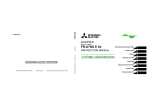
1.2
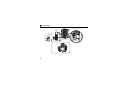
Parts
Connector for
communication
Mount the
accessory
terminal block to
connect to the
network.
(Refer to page 16.)
Terminating resistor selection switch
Select the resistor value of the terminating resistor. (Refer to page 13.)
Mounting
Front view
Rear
hole
view
SD L.RUN
1
RD L.ERR
RUN
1 2
ON
Mounting
hole
SW2
Mounting hole
Connector
Connect to the inverter option connector.
Terminal
layout
Operation status indication LED
Lit/flicker of the LED indicate operation status.(Refer to page 3.)
DA
DB
DG
SLD
1 2
ON
FG
SW2
2
PRE-OPERATION INSTRUCTIONS
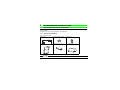
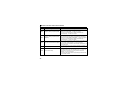
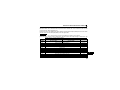
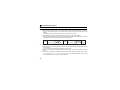
•Operation status indication LED
LED
Description
Lit when refresh data is properly received. Turns OFF when a data transmission is stopped for a
L.RUN
certain period of time.
• Lit when a communication error occurs in the own station and flickers when settings of switch, etc.
are changed while power is ON.
L.ERR
• Flickers when the Pr. 542 or Pr. 543 setting is changed.
Turn the power ON again or turn the RES signal ON. (Refer to page 37, 38.)
Lit during normal operation (5V is supplied in the board) (Lit even in the noncommunication status.)
RUN
Flickers when the master station is CC-Link ver.1 and the FR-A7NC is CC-Link ver.2 compatible.
(Refer to page 5.)
SD
Turns OFF when no data is transmitted.
RD
Lit when the received data carrier is detected.
REMARKS
⋅ Set the station number using Pr. 542 Communication station number (CC-Link). (Refer to page 37.)
⋅ Set transmission baud rate using Pr.543 Baud rate selection (CC-Link). (Refer to page 38.)
3
PRE-OPERATION INSTRUCTIONS
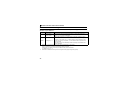
1.3
Inverter option specifications
Type
Power supply
Number of units
connected
Inverter plug-in option type, terminal block connectable
5VDC supplied from the inverter
42 units max. (Refer to page 43 for the number of stations occupied.) May be used with other
equipment.
0.3mm2 to 0.75mm2
Station type
Remote device station
Number of stations
CC-Link ver.1: occupies one station
occupied
CC-Link ver.2: occupies one station (selectable from among double, quadruple and octuple)
Communication cable CC-Link dedicated cable, CC-Link ver. 1.10 compatible CC-Link dedicated cable
Cable size
4
1
PRE-OPERATION INSTRUCTIONS
1.4
CC-Link version
1.4.1
CC-Link ver. 1.10
The conventional CC-Link products, whose inter-station cable lengths have equally been changed to 20cm
(7.87 inch) or more to improve the inter-station cable length restriction, are defined as CC-Link ver. 1.10. In
comparison, the conventional products are defined as CC-Link ver. 1.00.
Refer to the CC-Link Master Module Manual for the maximum overall cable lengths and inter-station cable
lengths of CC-Link ver. 1.00 and ver. 1.10.
CC-Link ver. 1.10 compatibility conditions
1) All modules that comprise a CC-Link system should be compatible with CC-Link ver. 1.10.
2) All data link cables should be CC-Link ver. 1.10 compatible, CC-Link dedicated cables.
(CC-Link ver. 1.10 compatible cables have a
logo or ver. 1.10 indication.)
CAUTION
• In a system that uses the CC-Link ver. 1.00 and ver. 1.10 modules and cables together, the maximum overall
cable length and inter-station cable length are as specified for CC-Link ver. 1.00.
1.4.2
CC-Link ver. 2
The FR-A7NC is compatible with CCLink ver.2.
Master station
Master station
(CC-Link ver.1)
(CC-Link ver.2)
When using the CC-Link ver.2 setting
with the FR-A7NC, the master station
CC-Link ver.1 CC-Link ver.2
CC-Link ver.1 CC-Link ver.2
needs to be compatible with the CCsetting
setting
setting
setting
Link ver.2.
For CC-Link ver.2, double, quadruple
and octuple settings can be used to Communication Communication Communication Communication
enabled
enabled
enabled
disabled
increase the remote register (RWr/w)
("RUN" LED flickers)
points.
5
2
INSTALLATION
2.1
Pre-installation instructions
Make sure that the input power of the inverter is OFF.
CAUTION
With input power ON, do not install or remove the plug-in option. Otherwise, the inverter and
plug-in option may be damaged.
For prevention of damage due to static electricity, touch nearby metal before touching this
product to eliminate static electricity from your body.
2.2
Installation procedure
2
The FR-E700 series has one connection connector for the plug-in option.
CAUTION
•
•
Always perform wiring to the main circuit terminals and control circuit terminals
before installing the option. Wiring cannot be performed after installing the
option.
For wiring to terminals RUN, FU, and SE of control circuit terminal, run cables to
prevent them from being caught between the option board and control circuit
terminal block as shown in the right figure. In case cables are caught, the
inverter may be damaged.
When the inverter cannot recognize that the option unit is mounted due to
improper installation, etc., "
•
•
•
Plug-in
option
" (option fault) is displayed.
When mounting/removing an option, hold the sides of the circuit board. Do not
press on the parts on the circuit board. Stress applied to the parts by pressing, etc. may cause a failure.
Take caution not to drop mounting screws during the mounting and removal of the option.
Pull the option straight out when removing. Pressure applied to the connector and to the circuit board may
break the option.
6
INSTALLATION
z Inverter with one front cover
(1) Remove the front cover from the inverter. (For removing the front cover, refer to the FR-E700
instruction manual.)
(2) Remove the PU cover from the front cover. Open the PU cover with a driver, etc. and remove it in the
direction of arrow as shown below.
(1) Front cover
*
(2) PU cover
* Open the PU cover, then open it toward the arrow
direction to remove.
REMARKS
• Because the voltage class, model name and serial (only voltage class is labeled for FR-E740-5.5K (FR-E740-120)
or higher) are written on the PU cover, replace a PU cover of a plug-in option front cover with the removed PU cover
from the inverter.
7
INSTALLATION
(3) Install the option protective cover.
(4) Securely fit the connector of the plug-in option to the inverter connector along the guides.
(5) Securely fix the both top and bottom of the plug-in option to the inverter with the accessory mounting
screws (tightening torque 0.33N•m to 0.40N•m). If the screw holes do not line up, the connector may
not have been plugged securely. Check for loose plugging.
(6) Remove the PU cover provided on the front cover for plug-in option and install the other PU cover,
which was removed in (2).
(7) Mount the already wired terminal block to the plug-in option. (Refer to Chapter 3 for wiring.)
(8) Install the front cover for plug-in option to the inverter.
2
Front cover
for plug-in option
(4)
(8)
Option connector
of inverter
(6) Replace
(3) Option protective cover
(7)
(5)
Mounting screws
REMARKS
•
When the option protective cover is not installed, the protective structure (JEM1030) changes to open type (IP00).
8
INSTALLATION
z Inverter with front covers 1 and 2
(1) Remove the front covers 1 and 2 from the inverter. (For removing the front cover, refer to the FR-E700
instruction manual.)
(2) Remove the PU cover from the front cover 2. For removing the PU cover, refer to page 7.
Front cover 1
Front cover 2
(1)
(1)
(2)
PU cover
REMARKS
• Because the voltage class is written on the PU cover, replace a PU cover of a plug-in option front cover with the
removed PU cover from the inverter.
9
INSTALLATION
(3) Install the front cover 1 to the inverter.
(4) Securely fit the connector of the plug-in option to the inverter connector along the guides.
(5) Securely fix the both top and bottom of the plug-in option to the inverter with the accessory mounting
screws (tightening torque 0.33N•m to 0.40N•m). If the screw holes do not line up, the connector may
not have been plugged securely. Check for loose plugging.
(6) Remove the PU cover provided on the front cover for plug-in option and install the other PU cover,
which was removed in (2).
(7) Mount the already wired terminal block to the plug-in option. (Refer to Chapter 3 for wiring.)
(8) Install the front cover for plug-in option to the inverter.
2
10
INSTALLATION
(4) Option connector of inverter
Front cover 1
(3)
Front cover for
plug-in option
(6)
(8)
Replace
(7)
(5) Mounting screws
Installation completed
11
3
3.1
(1)
(2)
(3)
WIRING
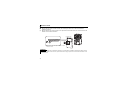
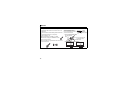
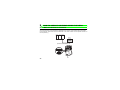
System configuration example
Programmable controller side
Mount the "QJ61BT11N", "AJ61QBT11", "A1SJ61QBT11", "AJ61BT11", "A1SJ61BT11" or "LJ61BT11" "CCLink system master/local module" on the main or extension base unit having the programmable controller
CPU used as the master station.
Inverter side
Mount the option (FR-A7NC) on the inverter.
Connect the programmable controller CC-Link module master station and the terminal block supplied with the
FR-A7NC with the CC-Link dedicated cable. After connecting the terminal block to the FR-A7NC, fit the front
cover.
Manual of the CC-Link master station
QJ61BT11N type
CC-Link System Master/Local Module
User's Manual ...SH-080394E
AJ61QBT11/A1SJ61QBT11 type
Control & Communication Link System
Master/Local Module User's Manual ...IB-66722
AJ61BT11/A1SJ61BT11 type
Control & Communication Link System
Master/Local Module User's Manual ...IB-66721
LJ61BT11 type
CC-Link System Master/Local Module User's
Manual ...SH-080895ENG
Inverter
Master station
QJ61BT11N,
etc.
Inverter
when only
inverters are
connected
Terminating
resistor
Terminating
resistor
Power
CC-Link dedicated cable supply
3
Up to 42
units can be
connected
Motor
Power
supply
Motor
Remote device station
REMARKS
• When the CPU has automatic refresh function (example: QnA series CPU)
When the END instruction is executed by the programmable controller CPU, the buffer memory is automatically refreshed to
enable communication with a remote device.
• When the CPU does not have automatic refresh function (example: AnA series CPU)
Sequence ladder logic is configured to perform direct communication with the buffer memory of the master station and to
enable communication with a remote device.
12
WIRING
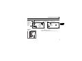
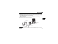
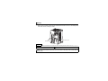
3.2
Connection of several inverters
An inverter can join the link system as a CC-Link remote device station, and such device stations can be
controlled and monitored with a user program of a programmable controller. These devices can be useful
components of an automated factory.
For the shield cable of the CC-Link dedicated cable, connect it to "SLD" of each unit and always earth
(ground) it via "FG".
Terminals SLD and FG are connected inside the unit.
Master module
Terminating
resistor *1
*1
*2
*3
DA
DB
DG
SLD
FG
Blue
White
Yellow
Shielded
twisted cable
FR-A7NC*2
DA
DB
DG
SLD
FG
FR-A7NC
Blue
White
Yellow
Shielded
twisted cable
Terminating
resistor
selection
switch (SW2)
DA
DB
DG
SLD
FG
*3
1
1 2
ON
Use the terminating resistors supplied with the programmable controller.
For the unit in the middle, set 1 and 2 of SW2 to OFF (without terminating resistor).
Perform setting of the terminating resistor selection switch (SW2).
(Refer to page 2 for the position of the switch.)
When connecting a terminating resistor separately, do not use a built-in
terminating resistor. (SW2 1-OFF, 2-OFF)
2
Description
Without
OFFOFF terminating
resistor
1 2
ON
ON OFF Do not use.
1 2
ON
OFF ON 130Ω
1 2
ON
ON ON 110Ω
130Ω is a resistance value for the CC-Link
ver.1.00 dedicated high performance
cable.
13
WIRING
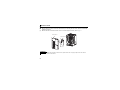
REMARKS
When performing online exchange
The built-in terminating resistor cannot be exchanged online since the terminating resistor is on the FR-A7NC board
and disconnected when the terminal block is removed from the FR-A7NC connector for communication. When
changing the FR-A7NC online, connect a terminating resistor supplied with a programmable controller master module
to the FR-A7NC after modifying it and do not use the internal terminating resistor (SW2 1-OFF, 2-OFF).
z Connection with the terminating resistor
Tube
Connect the terminating resistor between terminals
DA-DB of the FR-A7NC at the end.
Modify the terminating resistors supplied with the
programmable controller to use.
Cut
Cut the tube
When a resistor is not supplied with the master
module, use a resistor with 110Ω 1/2W available on the market.
(1) Maximum number of units connected to one master station (CC-Link ver.1.10)
42 units (when connections are inverters only)
If any other units are included, the number of stations occupied depends on the unit
and therefore the following conditions must be satisfied:
{(1 × a) + (2 × b) + (3 × c) + (4 × d)} ≤ 64
a: Number of units occupying 1 station c: Number of units occupying 3 stations
b: Number of units occupying 2 stations d: Number of units occupying 4 stations
{(16 × A) + (54 × B) + (88 × C)} ≤ 2304
A: Number of remote I/O ≤ 64
B: Number of remote device stations ≤ 42
C: Number of local, standby master and intelligent device stations ≤ 26
14
3
WIRING
(2) Maximum number of units connected to one master station (CC-Link ver.2.00)
42 units (when connections are inverter only)
If any other units are included, the number of stations occupied depends on the unit and
therefore the following conditions must be satisfied:
• {(a + a2 + a4 + a8) + (b + b2 + b4 + b8) × 2 + (c + c2 + c4 + c8) × 3 + (d + d2 + d4 + d8) × 4} ≤ 64
• {(a × 32 + a2 × 32 + a4 × 64 + a8 × 128) + (b × 64 + b2 × 96 + b4 × 192 + b8 × 384) + (c ×
96 + c2 × 160 + c4 × 320 + c8 × 640) + (d × 128 + d2 × 224 + d4 × 448 + d8 × 896)} ≤ 8192
• {(a × 4 + a2 × 8 + a4 × 16 + a8 × 32) + (b × 8 + b2 × 16 + b4 × 32 + b8 × 64) + (c × 12 +
c2 × 24 + c4 × 48 + c8 × 96) + (d × 16 + d2 × 32 + d4 × 64 + d8 × 128)} ≤ 2048
a: Number of single setting devices occupying one station
b: Number of single setting devices occupying two stations
c: Number of single setting devices occupying three stations
d: Number of single setting devices occupying four stations
a2: Number of double setting devices occupying one station
b2: Number of double setting devices occupying two stations
c2: Number of double setting devices occupying three stations
d2: Number of double setting devices occupying four stations
a4: Number of quadruple setting devices occupying one station
b4: Number of quadruple setting devices occupying two stations
c4: Number of quadruple setting devices occupying three stations
d4: Number of quadruple setting devices occupying four stations
a8: Number of octuple setting devices occupying one station
b8: Number of octuple setting devices occupying two stations
c8: Number of octuple setting devices occupying three stations
d8: Number of octuple setting devices occupying four stations
• 16 × A + 54 × B + 88 × C ≤ 2304
A: Numbers of remote I/O ≤ 64
B: Number of remote device stations ≤ 42
C: Number of local and intelligent device stations ≤ 26
15
WIRING
3.3
Connection cable
In the CC-Link system, use CC-Link dedicated cables.
If the cable used is other than the CC-Link dedicated cable, the performance of the CC-Link system is not
guaranteed.
For the specifications of the CC-Link dedicated cable, refer to the website of the CC-Link Partner
Association.
⋅ Website of the CC-Link Partner Association http://www.cc-link.org/
3.4
Wiring
(1) Strip off the sheath of the CC-Link dedicated cable and twist wires to use. If the length of the sheath
pealed is too long, a short circuit may occur among neighboring wires. If the length is too short, wires
might come off.
Use recommended cables. (Refer to page 16.) Recommended tightening torque : 0.22N⋅m to 0.25N⋅m
Wire the stripped cable after twisting it to prevent it from becoming loose. (Do not solder it.)
Cable stripping length
6.5mm
Use a blade type terminal as required.
16
3
WIRING
Recommended blade terminal
For wiring of the CC-link communication signal, two CCLink dedicated cables need to be twisted to wire to one
terminal block.
It is recommended to use the following blade terminal and
tool.
Recommended products (as of July 2010):
Phoenix Contact Co.,Ltd.
⋅Blade terminal model: AI-TWIN2 × 0,5-8WH
⋅Blade terminal crimping tool: CRIMPFOX 6T-F/6
Note the crimping method.
Hold the long side in a longitudinal direction and insert it
into the terminal block.
Connection of the shielded cable of the
CC-Link dedicated cable
Twist the shielded cable and
wire to the terminal SLD.
Use a compression tube and
junction terminal block.
Use of a compression tube
CC-Link dedicated
cable
Prevent looseness with
a compression tube
Shielded cable
Use of a junction terminal block
FR-A7NC
SLD
Junction terminal block
17
Shielded cable
FR-A7NC
SLD
Junction terminal block
WIRING
(2) Loosen the terminal screw and insert the cable into the terminal.
Screw Size
Tightening Torque
Cable Size
Screwdriver
M2
0.22N⋅m to 0.25N⋅m
0.3mm2 to 0.75mm2
Small
flat-blade screwdriver
(Tip thickness: 0.4mm /tip width:
2.5mm)
CAUTION
• Undertightening can cause cable disconnection or malfunction. Overtightening can cause a short circuit or
malfunction due to damage to the screw or unit.
3
(3) Connect the terminal block to the connector for communication of the communication option.
18
WIRING
(4) When wiring an inverter, which has front covers 1 and 2, pass the cable over the front cover 1 as shown
below. If a CC-Link cable is passed through underneath the inverter front cover 1, the bending radius
of the cable shortens, stressing the cable.
Front cover 2
Front cover 1
REMARKS
• If the terminal block of the FR-A7NC is removed, the built-in terminating resistor cannot be used. (Refer to page 13.)
CAUTION
When wiring, take care not to subject the cable to stress.
After wiring, wire offcuts must not be left in the inverter. They may cause a fault, failure or
malfunction.
19
4
INVERTER SETTING
4.1
Parameter list
The following parameters are used for the plug-in option (FR-A7NC).
Set the values according to need.
Parameter
Number
79
313 *1
314 *1
315 *1
338
339
340
342
349 *1
500 *1
501 *1
502 *2
541 *1
542 *1, *2, *3
543 *1, *2, *3
544 *1, *2
550 *2
*1
*2
*3
Name
Operation mode selection
Setting Range
0 to 4, 6, 7
0,
1,
3,
4,
7, 8, 11 to 16, 20, 25,
DO0 output selection
26, 46, 47, 64, 90, 91, 93, 95,
96, 98, 99, 100, 101, 103, 104,
DO1 output selection
107, 108, 111 to 116, 120, 125,
126, 146, 147, 164, 190, 191,
DO2 output selection
193, 195, 196, 198, 199, 9999
Communication operation command source
0, 1
Communication speed command source
0, 1, 2
Communication startup mode selection
0, 1, 10
Communication EEPROM write selection
0, 1
Communication reset selection
0, 1
Communication error execution waiting time
0 to 999.8s
Communication error occurrence count display
0
Stop mode selection at communication error
0 to 3
Frequency command sign selection (CC-Link)
0, 1
Communication station number (CC-Link)
1 to 64
Baud rate selection (CC-Link)
0 to 4
CC-Link extended setting
0, 1, 12, 14, 18
NET mode operation command source selection
0, 2, 9999
Minimum Initial Refer
Setting
to
Value
Increments
Page
1
0
22
1
9999
54
1
1
1
1
1
0.1s
1
1
1
1
1
1
1
0
0
0
0
0
0
0
0
0
1
0
0
9999
25
25
22
29
35
30
31
32
39
37
38
43
25
Parameters which can be displayed when the plug-in option (FR-A7NC) is mounted.
The setting is reflected after inverter reset or at the next power-ON.
"L.ERR" LED flickers if the setting is changed. If the inverter is reset, the setting is reflected and the LED turns OFF.
20
4
INVERTER SETTING
4.2
Operation mode setting
The inverter mounted with a communication option has three operation modes.
(1) PU operation [PU].............. Controls the inverter from the keys of the operation panel on the inverter or
parameter unit (FR-PU07/FR-PA07).
(2) External operation [EXT] ... Controls the inverter by switching ON/OFF external signals connected to
the control circuit terminals of the inverter.
(The inverter is factory-set to this mode.)
(3) Network operation [NET] ... Controls the inverter with instructions from the network via the
communication option.
(The operation signal and running frequency can be entered from the
control circuit terminals depending on the Pr. 338 Communication operation
command source and Pr. 339 Communication speed command source settings.
Refer to page 26.)
4.2.1
Operation mode indicator
Operation panel
Operation mode indicators
(The inverter operates according to the LED lit mode.)
PU: PU operation mode
EXT: External operation mode
NET: Network operation mode
21
INVERTER SETTING
4.2.2
Operation mode switching and communication startup mode (Pr. 79, Pr. 340)
(1) Operation mode switching conditions
Before switching the operation mode, check that:
1) The inverter is at a stop;
2) Both the STF and STR signals are OFF; and
3) The Pr. 79 Operation mode selection setting is correct.
(Set using the operation panel of the inverter or parameter unit (FR-PU07/FR-PA07).)
Refer to the Inverter Manual for details of Pr. 79.
(2) Operation mode selection at power ON and at restoration from instantaneous power
failure
The operation mode at power ON and at restoration from instantaneous power failure can be selected.
Set a value other than "0" in Pr. 340 to select the Network operation mode.
After started in Network operation mode, parameter write from the network is enabled. (Refer to page 78 for
a program example for parameter write.)
REMARKS
• Change of the Pr. 340 setting is applied valid power ON or an inverter reset.
• Pr. 340 can be changed with the operation panel in any operation mode.
22
4
INVERTER SETTING
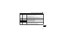
Pr. 340
Setting
Pr. 79
Setting
Operation Mode at Power ON or Power
Restoration
Operation Mode Switchover
0 (initial
value)
1
Switching among the External, PU, and NET operation mode is
External operation mode
enabled *1
PU operation mode
PU operation mode fixed
Switching between the external and NET operation mode is enabled
2
External operation mode
0
Switching to the PU operation mode is disallowed
3, 4
External/PU combined operation mode
Operation mode switching is disallowed
(initial
Switching among the External, PU, and NET operation mode is
value)
6
External operation mode
enabled while running.
X12 (MRS) signal ON ..... External operation mode Switching among the External, PU, and NET operation mode is enabled *1
7
X12 (MRS) signal OFF ... External operation mode External operation mode fixed (Forcibly switched to external
operation mode.)
0
NET operation mode
1
PU operation mode
2
NET operation mode
Same as when Pr. 340 = "0"
3, 4
External/PU combined operation mode
1
NET operation mode
6
X12 (MRS) signal ON .... NET operation mode
7
X12 (MRS) signal OFF ... External operation mode
0
NET operation mode
Switching between the PU and NET operation mode is enabled *2
1
PU operation mode
Same as when Pr. 340 = "0"
NET operation mode
NET operation mode fixed
2
10
3, 4
External/PU combined operation mode
Same as when Pr. 340 = "0"
Switching between the PU and NET operation mode is enabled while
6
NET operation mode
running *2
7
External operation mode
Same as when Pr. 340 = "0"
*1 Operation mode cannot be directly changed between the PU operation mode and Network operation mode.
*2 Operation mode can be changed between the PU operation mode and Network operation mode with
X65 signal.
23
of the operation panel and
INVERTER SETTING
(3) Operation mode switching method
External operation
When "0 or 1" is set in Pr. 340
Switching with the PU
Switching through the network
Switch to External
operation mode
through the network.
Switch to Network operation
mode through the network.
Press
on
the PU to light
Network operation
When "10" is set in Pr. 340
Press
on
the PU to light
PU operation
4
Press
on the PU to light
Network operation
PU operation
Press
on the PU to light
For the switching method with the external terminal, refer to the Inverter Manual.
Refer to page 63 for the switching method through the network.
CAUTION
• When starting the inverter in Network operation mode at power ON or an inverter reset, set a value other
than "0" in Pr. 340. (Refer to page 22)
• When setting a value other than "0" in Pr. 340, make sure that the initial settings of the inverter are correct.
24
INVERTER SETTING
4.3
Start and speed command sources (Pr. 338, Pr. 339, Pr. 550)
(1) Select command source for the Network operation mode (Pr. 550)
A control location for the Network operation mode can be selected from either the RS-485
communication with the PU connector or a communication option.
When using a communication option, set "0 or 9999 (initial value)" in Pr. 550.
Parameter
Number
Name
Initial Value
Setting
Range
0
2
550
NET mode operation
command source selection
9999
9999
Refer to the inverter manual for details.
25
Description
The communication option is the
command source when NET
operation mode.
PU connector is the command source
when NET operation mode.
Automatic communication option
recognition
Normally, PU connector is the
command source. When a
communication option is mounted,
the communication option is the
command source.
INVERTER SETTING
(2) Selection of control source for the Network operation mode (Pr. 338, Pr. 339)
⋅ There are two command types: the start command, which controls the signals related to the inverter
start command and function selection, and the speed command, which controls signals related to
frequency setting.
⋅ In Network operation mode, the commands from the external terminals and communication (PU
connector or communication option) are as listed below.
Operation Pr. 338 Communication operation
command source
Location
Pr. 339 Communication speed
Selection
command source
Fixed
function
(terminalequivalent
function)
Pr. 178 to Pr. 184 setting
Selective function
0
1
2
3
4
5
Running frequency from
communication
Terminal 2
Terminal 4
Low-speed operation
command/remote setting
RL
clear/stop-on contact
selection 0
Middle-speed operation
RM command/remote setting
function
High-speed operation
RH command/remote setting
function
Second function selection/
RT
stop-on contact selection 1
AU Terminal 4 input selection
JOG Jog operation selection
0: NET
0:
NET
1:
1: External
2:
External External
0:
NET
1:
2:
External External
NET
—
NET
NET
—
NET
—
External
—
—
External
—
—
External
—
Remarks
External
4
NET
External
NET
External
NET
External
NET
External
NET
External
NET
External
NET
—
Combined
—
External
—
Pr. 59 = "0"
(multi-speed)
Pr. 59 = "1, 2"
(remote)
Pr. 270 = "1"
(stop-on-contact)
Pr. 270 = "1"
(stop-on-contact)
Combined
External
26
INVERTER SETTING
Operation Pr. 338 Communication operation
command source
Location
Pr. 339 Communication speed
Selection
command source
OH
8
REX 15-speed selection
10
X10 Inverter run enable signal
PU operation external
X12
interlock
X14 PID control valid terminal
Brake opening completion
BRI
signal
PU-External operation
X16
switchover
X18 V/F switchover
Output stop
Pr. 178 to Pr. 184 setting
Selective function
14
15
16
18
24 MRS
27
NET
1:
2:
External External
0:
NET
1:
2:
Remarks
External External
External
NET
External
NET
External
Pr. 59 = "0"
(multi-speed)
External
External
NET
External
NET
NET
External
External
External
NET
Combined
PU operation interlock
Start self-holding
selection
Forward rotation
60 STF
command
25 STOP
0:
1: External
External thermal relay
input
7
12
0: NET
External
External
External
—
External
NET
External
Pr. 79 ≠ "7"
Pr. 79 = "7"
When the X12
signal is not
assigned
INVERTER SETTING
Pr. 178 to Pr. 184 setting
Selective function
Operation Pr. 338 Communication operation
command source
Location
Pr. 339 Communication speed
Selection
command source
61 STR
62 RES
65
X65
66
X66
67
X67
Reverse rotation
command
Inverter reset
PU/NET operation
switchover
External/NET operation
switchover
Command source
switchover
0: NET
0:
NET
1:
1: External
2:
External External
0:
NET
NET
1:
2:
Remarks
External External
External
External
External
External
External
[Explanation of table]
External
: Command is valid only from control terminal.
NET
: Command only from communication is valid.
Combined : Command from both control terminal and communication is valid.
—
: Command from either of control terminal and communication is invalid.
4
REMARKS
• The command source of communication is as set in Pr. 550 and Pr. 551.
• The Pr. 338 and Pr. 339 settings can be changed while the inverter is running when Pr. 77 = "2". Note that the setting
change is applied after the inverter has stopped. Until the inverter has stopped, communication operation command
source and communication speed command source before the setting change are valid.
28
INVERTER SETTING
4.3.1
Communication EEPROM write selection (Pr. 342)
When parameter write is performed from the communication option, write to RAM is enabled. Set when
frequent parameter changes are necessary.
Parameter
Number
342
Name
Communication EEPROM write
selection
Initial
Value
Setting
Range
0
0
1
Description
Parameter values written by
communication are written to the
EEPROM and RAM.
Parameter values written by
communication are written to the RAM.
⋅ When changing the parameter values frequently, set "1" in Pr. 342 to write them to the RAM.
Performing frequent parameter write with "0 (initial value)" (EEPROM write) set will shorten the life of the
EEPROM.
REMARKS
• When "1" (write to RAM only) is set in Pr. 342, powering OFF the inverter will erase the changed parameter values.
Therefore, the parameter values available when power is switched ON again are the values stored in EEPROM
previously.
29
INVERTER SETTING
4.4
Operation at communication error occurrence
4.4.1
Operation selection at communication error occurrence (Pr. 500 to Pr. 502)
You can select operations at communication error occurrences by setting Pr. 500 to Pr. 502 under network
operation.
(1) Waiting time for the communication line error output after a communication error
Waiting time for the communication error output after a communication line error occurrence can be
set.
Parameter
Number
Name
Setting Range
Minimum Setting
Increments
Initial Value
500
Communication error
execution waiting time
0 to 999.8s
0.1s
0
Communication line status
Normal
Error
Normal
Error
Communication error (E.OP1)
Pr. 500
setting time
Alarm signal (LF)
(Pr. 502 = 3)
4
Recognition
Pr. 500
setting time
ON
When a communication line error occurs and lasts longer than the time set in Pr. 500, it is recognized
as a communication error.
If the communication returns to normal within the time, it is not recognized as a communication error,
and the operation continues.
30
INVERTER SETTING
(2) Displaying and clearing the communication error count
The cumulative count of communication error occurrences can be displayed.
Write "0" to clear this cumulative count.
Parameter
Number
Name
Setting Range
Minimum Setting
Increments
Initial Value
501
Communication error
occurrence count display
0
1
0
Count timing depending on
communication line status
Normal
Error
Normal
Incremented by 1
Error
Incremented by 1
At the point of communication line error occurrence, Pr. 501 Communication error occurrence count
display is incremented by 1.
CAUTION
• Communication error count is temporarily stored in the RAM. The error count is stored in EEPROM only
once per hour. If power reset or inverter reset is performed, Pr. 501 setting will be the one that is last stored
to EEPROM depending on the reset timing.
31
INVERTER SETTING
(3) Inverter operation at a communication error occurrence
How the inverter operates at a communication line error or an option unit fault can be set.
Parameter
Number
Name
Setting Range
Minimum Setting
Increments
Initial Value
502
Stop mode selection at
communication error
0, 1, 2, 3
1
0
About setting
z Operation at an error occurrence
Error Definition
Communication line
Communication
option itself
Pr. 502 Setting
0
1
2
3
0, 3
1, 2
Operation
Indication
Fault Output
Continued *
Normal indication *
Not provided *
Coast to stop
Decelerated to stop
E. 1 lit
E. 1 lit after stop
Provided
Provided after stop
4
* When the communication returns to normal within the time period set in Pr. 500, the communication option error (E.OP1)
does not occur.
z Operation at error recognition after elapse of Pr. 500 time
Error Definition
Communication line
Communication
option itself
Pr. 502 Setting
Operation
Indication
Fault Output
0
1
2
3
0, 3
1, 2
Coast to stop
E.OP1 lit
Decelerated to stop
E.OP1 lit after stop
Provided
Provided after stop
Continued
Coast to stop
Decelerated to stop
Normal indication
E. 1 lit
E. 1 lit after stop
Not provided
Provided
Provided after stop
32
INVERTER SETTING
z Operation at error removal
Error Definition
Pr. 502 Setting
Communication line
0
1
2
3
Communication
option itself
0, 3
1, 2
Operation
Indication
Fault Output
Kept stopped
E.OP1 kept lit
Kept provided
Restart
Continued
Normal indication
Not provided
Kept stopped
E. 1 kept lit
Kept provided
CAUTION
• Communication line error [E.OP1 (fault data: HA1)] is an error that occurs on the communication line.
Communication option error [E. 1 (fault data: HF1)] is an error that occurs in the communication circuit
inside the option.
• Fault output indicates the fault output signal (ALM signal) and fault bit output.
• When the fault output setting is active, fault records are stored in the faults history.
When the fault output setting is not active, fault record is overwritten to the faults history temporarily but
not stored.
After the error is removed, the fault indication is reset, changing the display back to normal, and the last
fault is displayed in the faults history.
• When the Pr. 502 setting is "1" or "2", the deceleration time is the normal deceleration time setting (e.g. Pr. 8,
Pr. 44, Pr. 45).
• The acceleration time at a restart is the normal acceleration time setting (e.g. Pr. 7, Pr. 44).
• When the Pr. 502 setting is "2", the operation/speed command at a restart is the one given before the error
occurrence.
• When a communication line error occurs at the Pr. 502 setting of "2", removing the error during deceleration
causes acceleration to restart at that point. (Acceleration is not restarted if the error is that of the option unit
itself.)
33
INVERTER SETTING
4.4.2
Fault and measures
(1) The inverter operates as follows at fault occurrences.
Fault
Location
Status
Inverter operation
Data communication
Communication Inverter operation
line
Data communication
Communication Inverter
operation
option
connection
Data
communication
Communication error
option
Inverter
Error of
operation
communication
Data
option itself
communication
Inverter
Network
Operation
Operation Mode
External
Operation
Inverter trip
Continued
Inverter trip *
Stop
Inverter trip
Continued
Continued
Stop
Inverter trip
Continued
Continued
Stop
Inverter trip *
Inverter trip *
Inverter trip *
Continued
Continued
Continued
Inverter trip *
Continued
Continued
Stop
Stop
Stop
PU Operation
4
* Depends on the Pr. 502 setting.
(2) Measures at error occurrences
Fault Indication
E.OP1
E.1
Error Definition
Communication line
error
Option fault
Measures
Check the LED status of the option unit and remove the cause of the
alarm. (Refer to page 85 for LED indication status)
Inspect the master.
Check the connection between the inverter and option unit for poor
contact, etc. and remove the cause of the error.
When faults other than the above are displayed, refer to the inverter manual and remove the cause of the error.
34
INVERTER SETTING
4.5
Inverter reset
(Refer to page 82 for an inverter reset program example.)
(1) Operation conditions of inverter reset
Which resetting method is allowed or not allowed in each operation mode is described below.
Resetting Method
Inverter reset (Refer to page 66) *1
Reset from the
Error reset (RY1A) at inverter fault
network
(Refer to page 53) *2
Turn ON the inverter RES signal (terminal RES)
Switch OFF inverter power
Reset from the Inverter reset
PU/operation
Reset at inverter fault
panel
*1
*2
Network
Operation
Allowed
Pr.349 = 0
Pr.349 = 1
Allowed
Enabled
Enabled
Operation Mode
External
PU
Operation
Operation
Disallowed
Disallowed
Allowed
Allowed
Disallowed
Disallowed
Enabled
Enabled
Enabled
Enabled
Enabled
Enabled
Enabled
Enabled
Enabled
Enabled
Inverter reset can be made any time.
Reset can be made only when the protective function of the inverter is activated.
CAUTION
• When a communication line error has occurred, reset cannot be made from the network.
• The inverter is set to the External operation mode if it has been reset in Network operation mode in the
initial status.
To resume the network operation, the inverter must be switched to the Network operation mode again.
Set a value other than "0" in Pr. 340 to start in Network operation mode. (Refer to page 22.)
• Communication continues during inverter reset. (The inverter cannot be controlled for about 1s after
release of a reset command .)
35
INVERTER SETTING
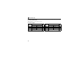
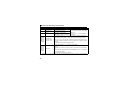
(2) Error reset operation selection at inverter fault
When used with the communication option, an error reset command* from network can be invalid in
the external operation mode or PU operation mode.
Parameter
Number
349
Name
Communication reset
selection
Initial
Value
Setting
Range
0
0
1
Function
Error reset* is enabled independently of
operation mode
Error reset* is enabled only in the Network
operation mode
* RY1A (Refer to page 53)
4
36
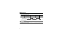
INVERTER SETTING
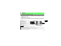
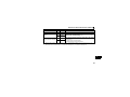
4.6 CC-Link function setting
4.6.1 Station number setting (Pr. 542)
Use Pr. 542 Communication station number (CC-Link) to set station number of the inverter. Set this parameter
within the range of 1 to 64.
Parameter Number
Name
Initial Value
Setting Range
542
Communication station number (CC-Link)
1
1 to 64
CAUTION
• Use different station numbers for different devices. (If different devices have the same station number, the
communication cannot be performed properly. )
Connection example
CC-Link
master module
Station 00
Programmable controller
Inverter No.1
Inverter No.2
Inverter No.3
remote I/O station
(FR-A7NC)
(FR-A7NC)
(FR-A7NC)
(occupies one station) Remote device station Remote device station Remote device station
Station 01
Station 02
Station 03
Station 04
Number of stations connected is 4
REMARKS
• Set consecutive numbers for the station numbers. (Do not skip a number in sequence like "station number 1 - station number
2- station number 4".)
The station number does not have to match with the physical connection sequence. (There is no problem with having the
physical connection sequence like "station number 1 - station number 3 - station number 4 - station number 2".)
• One inverter occupies one station. (One remote device station)
• "L.ERR" LED flickers if the setting is changed. When power is switched ON again or the RES signal is turned ON, the
setting value is reflected and the LED turns OFF.
37
INVERTER SETTING
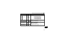
4.6.2
Baud rate setting (Pr. 543)
Set the transmission speed. (Refer to the manual for the CC-Link master module for details of transmission
speed.)
Parameter Number
543
Name
Baud rate selection (CC-Link)
Initial Value Setting Range Transmission Speed
0
0
1
2
3
4
156kbps
625kbps
2.5Mbps
5Mbps
10Mbps
REMARKS
• "L.ERR" LED flickers if the setting is changed. When power is switched ON again or the RES signal is turned ON,
the setting value is reflected and the LED turns OFF.
38
4
INVERTER SETTING
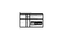
4.6.3
Frequency command with sign (Pr. 541)
By frequency command with sign, start command (forward rotation/reverse rotation) can be inversed to operate.
Make selection of sign for the frequency command from RWw1.
Parameter Numbers
Name
Initial Value Setting Range
541
Pr.541
Setting
0
1
Sign
Frequency command sign selection (CC-Link)
Setting Range
0
0, 1
Actual Frequency Command
Not used 0 to 40000
0 to 400.00Hz
-32768 to 32767 (two's complement) -327.68 to 327.67Hz
With
Relationship between the start command and sign (Pr.541 = "1")
Start Command Sign of the Frequency Command Actual Run Command
Forward rotation
Reverse rotation
+
+
-
Forward rotation
Reverse rotation
Reverse rotation
Forward rotation
REMARKS
• When Pr.541 = 1(with sign)
• When EEPROM write is specified with the RYE, write mode error (error code H01) will occur.
• When concurrent execution of both RYD and RYE is enabled (when a value other than 0 is set in Pr.544) and both
RYD and RYE are turned ON, RYD has precedence.
• When power is turned ON (inverter reset), the initial setting status of the sign bit is "positive" and the set
frequency is "0Hz". (EEPROM value is not reflected.)
Note that the operation mode when power is turned ON (inverter reset) is PU or External combined operation
(Pr.79 = 1, 3), the set frequency is EEPROM value.
• When set frequency is written with the instruction code of HED and HEE, the sign of the frequency command is
not changed.
39
5
FUNCTION OVERVIEW
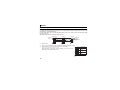
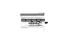
5.1
Function block diagram
Inverter
Buffer
memory
Input
Output
Inverter CPU
3) CC-Link
dedicated
cable
I/O interface
2) Buffer memory
access
CPU
FR-A7NC
CC-Link interface
1) I/O signals
CC-Link interface
Programmable controller
CC-Link system master/local module
Interface with
programmable controller
Programmable controller CPU
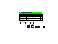
Using function blocks, this section explains I/O data transfer to/from an inverter in CC-Link:
• Link refresh is continuously executed between the master station and inverter in the CC-Link system at
intervals of 1.1ms to 141ms (per station).
1) These are I/O signals assigned to the CC-Link system master/local module. These signals are used for
communication between the programmable controller CPU and CC-Link system master/local module.
Refer to page 52 for details of the signal.
2) Reading of data input to the inverter, writing of inverter output data, and reading of a faulty CC-Link station
are available. Automatic refresh function enables reading from/writing to buffer memory. (Use FROM/TO
command of the sequence program to synchronize without using the automatic refresh function.) Refer
to CC-Link system master/local module manual for the buffer memory details.
3) CC-Link communication start command is given from the sequence program. After the CC-Link
communication starts, link refresh is always performed asynchronously (or synchronously) with execution
of sequence program.
For details, refer to the CC-Link system master/local module manual.
40
5
FUNCTION OVERVIEW
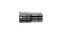
5.2
Output from the inverter to the network
Main items which can be output from the inverter to the master and their descriptions are explained below.
Item
Description
Refer to Page
Inverter status monitor
The output terminal status of the inverter can be monitored.
Output frequency monitor
The output frequency can be monitored.
Output current monitor
The output current can be monitored.
63
Output voltage monitor
The output voltage can be monitored.
63
Special monitor
The monitor data selected can be checked.
63
Faults history
Fault records can be checked.
Data at alarm occurrence
The inverter status at alarm occurrence can be checked.
61
Operation mode
The current operation mode can be checked.
63
Parameter read
Parameter settings can be read.
65
Read of set frequency
The current set frequency can be read.
64
REMARKS
• Refer to the inverter manual for functions controllable from the network in each operation mode.
41
54
60, 63
61, 64
FUNCTION OVERVIEW
5.3
Input to the inverter from the network
Main items which can be commanded from the master to the inverter and their descriptions are explained
below.
Item
Description
Refer to Page
Forward rotation command
Give the forward rotation command.
52
Reverse rotation command
Give the reverse rotation command.
52
Input terminal function command Execute functions assigned to the inverter input terminals.
52
Inverter output stop command
Stop the inverter output.
52
Error reset
Reset the inverter only when an inverter alarm occurs.
53
Frequency setting
Set the frequency.
57, 64
Monitor command
Specify the description monitored.
57, 63
Operation mode specification
Set the operation mode.
63
Faults history clear
Erase past eight fault records.
65
All parameter clear
Return the parameter descriptions to the initial value.
65
Inverter reset
Reset the inverter.
66
Parameter write
Write parameter settings.
65
PID control
PID set point, PID measured value and PID deviation can be
input from the network.
59
5
REMARKS
• Refer to the inverter manual for functions controllable from the network in each operation mode.
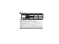
42
6
I/O SIGNAL LIST
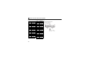
6.1
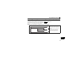
CC-Link extended setting (Pr. 544)
Remote register function can be extended.
Parameter
Number
Name
Initial Setting
Value Range CC-Link Ver.
0
544
*1
*2
CC-Link extended
setting
0
1
12 *2
14 *2
18 *2
1
2
Description
Occupies one station
(FR-E500 series compatible) *1
Occupies one station
Occupies one station double
Occupies one station quadruple
Occupies one station octuple
44
47
48
49
50
The program used for conventional series inverter (FR-E500 series) can be used.
When RYD, RYE, and RYF turn ON simultaneously, only one of them is executed.
The upper 8 bits of RWw2 are not link parameter extended setting.
When using double, quadruple and octuple settings of the CC-Link ver.2, station data of the master station must
be set to double, quadruple and octuple also.
(If the master station is CC-Link ver.1 compatible station, the above setting cannot be made.)
REMARKS
• The setting change is reflected after an inverter reset. (Refer to page 35 for inverter reset.)
43
Refer
to page
I/O SIGNAL LIST
6.2
I/O signal list
6.2.1
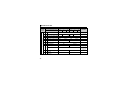
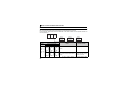
I/O signal when CC-Link ver.1 one station (FR-E500 series compatible)
is occupied (Pr. 544 = 0)
(1) Remote I/O (32 points)
Refer
to
Page
Device
No.
52
52
RXn0
RXn1
Forward running
Reverse running
54
54
52
RXn2
Running (terminal RUN function) *3
54
52
RXn3
Up to frequency (SU signal)
54
52
RXn4
Overload alarm (OL signal)
54
RYn5
Forward rotation command
Reverse rotation command
High-speed operation command
(terminal RH function) *1
Middle-speed operation command
(terminal RM function) *1
Low-speed operation command
(terminal RL function) *1
Not used
⎯
RXn5
⎯
RYn6
Second function selection (RT signal) *2
52
RXn6
RYn7
RYn8
RYn9
RYnA
RYnB
RYnC
RYnD
Terminal 4 input selection (AU signal) *2
Not used
Output stop (terminal MRS function) *1
Not used
Reset (terminal RES function) *1
Monitor command
Frequency setting command (RAM)
Frequency setting command
(RAM, EEPROM)
Instruction code execution request
52
⎯
52
⎯
52
53
53
RXn7
RXn8
RXn9
RXnA
RXnB
RXnC
RXnD
53
RXnE
53
RXnF
Not used
Frequency detection
(terminal FU function) *3
Error (terminal ABC function) *3
Not used
Pr. 313 assignment function (DO0) *4
Pr. 314 assignment function (DO1) *4
Pr. 315 assignment function (DO2) *4
Monitoring
Frequency setting completion (RAM)
Frequency setting completion
(RAM, EEPROM)
Instruction code execution completion
Device
No.
RYn0
RYn1
RYn2
RYn3
RYn4
RYnE
RYnF
Signal
Signal
Refer
to
Page
54
54
⎯
54
54
54
54
55
55
55
44
6
I/O SIGNAL LIST
Device
No.
Signal
RY(n+1)0
Reserved
to
RY(n+1)7
RY(n+1)8 Not used
(initial data process completion flag)
Not used
RY(n+1)9 (initial data process request flag)
RY(n+1)A Error reset request flag
RY(n+1)B
Reserved
to
RY(n+1)F
Refer
to
Page
⎯
⎯
⎯
53
⎯
Device
No.
Signal
RX(n+1)0
Reserved
to
RX(n+1)7
RX(n+1)8 Not used
(initial data process request flag)
Not used
RX(n+1)9 (initial data process completion flag)
RX(n+1)A Error status flag
RX(n+1)B Remote station ready
RX(n+1)C
Reserved
to
RX(n+1)F
Refer
to
Page
⎯
⎯
⎯
55
55
⎯
("n" indicates a value determined according to the station number setting.)
*1 These signals are set in the initial status. Using Pr. 180 to Pr. 184, you can change input signal functions.
Signals of the RYn0 and RYn1 cannot be changed. Even when changed using Pr. 178 and Pr. 179, the settings are
invalid.
Refer to the inverter manual for details of Pr. 178 to Pr. 184.
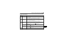
*2 Signals of the RY6 and RY7 cannot be changed.
*3 These signals are set in the initial status. Using Pr. 190 to Pr. 192, you can change output signal functions.
Refer to page 56 for signals which can be assigned.
*4 Output signal can be assigned using Pr. 313 to Pr. 315.
Refer to page 56 for signals which can be assigned.
45
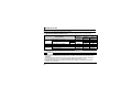
I/O SIGNAL LIST
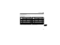
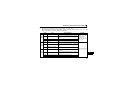
(2) Remote register
Address
Description
Upper 8 Bits
Lower 8 Bits
Refer
to
Page
Address
Description
RWwn
Monitor code 2
Monitor code 1
57
RWrn
First monitor value
Set frequency (0.01Hz increments) *2
57
RWrn+1
Second monitor value
RWwn+1
H00 (arbitrary) *1 Instruction code
58
RWrn+2
Reply code
RWwn+2
RWwn+3
Write data
58
RWrn+3
Read data
("n" indicates a value determined according to the station number setting.)
*1 The above 8 bit is always H00 even if a value other than H00 is set.
*2 When Pr. 37 is not equal to "0", this will be machine speed display (1 increments).
Refer
to
Page
60
60
60
60
6
46
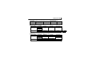
I/O SIGNAL LIST
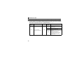
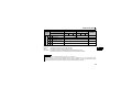
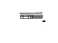
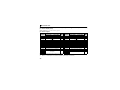
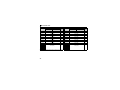
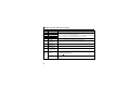
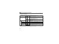
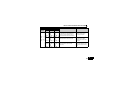
6.2.2
I/O signal when CC-Link ver.1 one station is occupied (Pr. 544 = "1")
(1) Remote I/O (32 points)
Same as when Pr. 544 = "0" (Refer to page 44)
(2) Remote register
Address
RWwn
Upper 8 Bits
Lower 8 Bits
Refer
to
Page
Monitor code 2
Monitor code 1
Description
Address
Description
Upper 8 Bits
Lower 8 Bits
Refer
to
Page
57
RWrn
First monitor value
60
RWwn+1
Set frequency (0.01Hz increments) *1
57
RWrn+1
Second monitor value
60
RWwn+2
Link parameter
extended setting
58
RWrn+2
58
RWrn+3
RWwn+3
Instruction code
Write data
Reply code 2
Read data
("n" indicates a value determined according to the station number setting.)
*1 When Pr. 37 is not equal to "0", this will be machine speed display (1 increments).
47
Reply code 1
60
60
I/O SIGNAL LIST
6.2.3
I/O signal when CC-Link ver.2 double setting is selected (Pr. 544 = "12")
(1) Remote I/O (32 points)
Same as when Pr. 544 = "0" (Refer to page 44)
(2) Remote register
Address
RWwn
RWwn+1
RWwn+2
Upper 8 Bits
Lower 8 Bits
Refer
to
Page
Monitor code 2
Monitor code 1
57
RWrn
First monitor value
60
57
RWrn+1
Second monitor value
60
58
RWrn+2
Description
Set frequency (0.01Hz increments) *1
Link parameter
extended setting
Instruction code
Address
Description
Upper 8 Bits
Reply code 2
Lower 8 Bits
Reply code 1
Refer
to
Page
60
RWwn+3
Write data
58
RWrn+3
Read data
60
RWwn+4
Monitor code 3
58
RWrn+4
Third monitor value
61
61
RWwn+5
Monitor code 4
58
RWrn+5
Fourth monitor value
RWwn+6
Monitor code 5
58
RWrn+6
Fifth monitor value
61
RWwn+7
Monitor code 6
58
RWrn+7
Sixth monitor value
61
("n" indicates a value determined according to the station number setting.)
*1 When Pr. 37 is not equal to "0", this will be machine speed display (1 increments).
6
48
I/O SIGNAL LIST
6.2.4
I/O signal when CC-Link ver.2 quadruple setting is selected (Pr. 544 = "14")
(1) Remote I/O (32 points)
Same as when Pr. 544 = "0" (Refer to page 44)
(2) Remote register
Address
RWwn
RWwn+1
RWwn+2
RWwn+3
RWwn+4
RWwn+5
RWwn+6
RWwn+7
RWwn+8
RWwn+9
RWwn+A
RWwn+B
RWwn+C
RWwn+D
RWwn+E
RWwn+F
Description
Upper 8 Bits
Lower 8 Bits
Monitor code 2
Monitor code 1
Set frequency (0.01Hz increments)*2
Link parameter
Instruction code
extended setting
Write data
Monitor code 3
Monitor code 4
Monitor code 5
Monitor code 6
Faults history No.
H00
PID set point (0.01% increments) *1
PID measured value
(0.01% increments) *1
PID deviation (0.01% increments) *1
H00 (Free)
Refer
to
Page
Address
57
57
RWrn
RWrn+1
58
RWrn+2
58
58
58
58
58
58
59
RWrn+3
RWrn+4
RWrn+5
RWrn+6
RWrn+7
RWrn+8
RWrn+9
59
RWrn+A
Fault record (output current)
61
59
RWrn+B
RWrn+C
RWrn+D
RWrn+E
RWrn+F
Fault record (output voltage)
Fault record (energization time)
61
61
H00 (Free)
⎯
⎯
Description
Upper 8 Bits
Reply code 2
Reply code 1
Read data
Third monitor value
Fourth monitor value
Fifth monitor value
Sixth monitor value
Faults history No.
Fault data
Fault record (output frequency)
("n" indicates a value determined according to the station number setting.)
*1 When Pr. 128 = "50, 51, 60, 61", they are valid.
*2 When Pr. 37 is not equal to "0", this will be machine speed display (1 increments).
49
Lower 8 Bits
First monitor value
Second monitor value
Refer
to
Page
60
60
60
60
61
61
61
61
61
61
I/O SIGNAL LIST
6.2.5
I/O signal when CC-Link ver.2 octuple setting is selected (Pr. 544 = "18")
(1) Remote I/O (32 points)
Same as when Pr. 544 = "0" (Refer to page 44)
(2) Remote register
Address
RWwn
RWwn+1
RWwn+2
RWwn+3
RWwn+4
RWwn+5
RWwn+6
RWwn+7
RWwn+8
RWwn+9
RWwn+A
RWwn+B
RWwn+C
RWwn+D
RWwn+E
RWwn+F
RWwn+10
*1
*2
Description
Upper 8 Bits
Lower 8 Bits
Refer
to
Page
Address
57
57
RWrn
RWrn+1
Monitor code 2
Monitor code 1
Set frequency (0.01Hz increments) *1
Link parameter
Instruction code
extended setting
Write data
Monitor code 3
Monitor code 4
Monitor code 5
Monitor code 6
Faults history No.
H00
PID set point (0.01% increments) *1
PID measured value (0.01% increments) *1
PID deviation (0.01% increments) *1
58
RWrn+2
58
58
58
58
58
58
59
59
59
H00 (Free)
⎯
RWrn+3
RWrn+4
RWrn+5
RWrn+6
RWrn+7
RWrn+8
RWrn+9
RWrn+A
RWrn+B
RWrn+C
RWrn+D
RWrn+E
RWrn+F
Link parameter
extended setting
Instruction code
59
RWrn+10
Description
Upper 8 Bits
Lower 8 Bits
First monitor value
Second monitor value
Reply code 2
Refer
to
Page
60
60
Reply code 1
60
Read data
Third monitor value
Fourth monitor value
Fifth monitor value
Sixth monitor value
Faults history No.
Fault data
Fault record (output frequency)
Fault record (output current)
Fault record (output voltage)
Fault record (energization time)
60
61
61
61
61
61
61
61
61
61
H00 (Free)
⎯
Reply code
61
6
When Pr. 128 = "50, 51, 60, 61", they are valid.
When Pr. 37 is not equal to "0", this will be machine speed display (1 increments).
50
I/O SIGNAL LIST
Address
RWwn+11
RWwn+12
RWwn+13
RWwn+14
RWwn+15
RWwn+16
RWwn+17
RWwn+18
RWwn+19
RWwn+1A
RWwn+1B
RWwn+1C
RWwn+1D
RWwn+1E
RWwn+1F
Refer
to
Page
Address
Write data
Link parameter
Instruction code
extended setting
Write data
Link parameter
Instruction code
extended setting
Write data
Link parameter
Instruction code
extended setting
Write data
Link parameter
Instruction code
extended setting
Write data
59
RWrn+11
Read data
61
59
RWrn+12
Reply code
61
59
RWrn+13
Read data
61
59
RWrn+14
Reply code
61
59
RWrn+15
Read data
61
59
RWrn+16
Reply code
61
59
RWrn+17
Read data
61
59
RWrn+18
Reply code
61
59
Read data
61
H00 (Free)
⎯
RWrn+19
RWrn+1A
RWrn+1B
RWrn+1C
RWrn+1D
RWrn+1E
RWrn+1F
H00 (Free)
⎯
Description
Upper 8 Bits
Lower 8 Bits
("n" indicates a value determined according to the station number setting.)
51
Description
Upper 8 Bits
Lower 8 Bits
Refer
to
Page
7
DETAILS OF INPUT AND OUTPUT SIGNALS
The following device No. are those for station 1.
For stations 2 and later, the device No. are different. (Refer to the master module manual for
correspondence between the device No. and station number)
7.1
Details of remote input and output signals
7.1.1
Output signals (master module to inverter (FR-A7NC))
The output signals from the master module are indicated. (Input signals to inverter)
Device
No.
Signal
RY0
Forward rotation command *2
RY1
Reverse rotation command *2
RY2
RY3
RY4
RY6
RY7
RY9
RYB
*1
*2
*3
High-speed operation command
(terminal RH function) *1
Middle-speed operation command
(terminal RM function) *1
Low-speed operation command
(terminal RL function) *1
Second function selection (RT signal) *3
Terminal 4 input selection (AU signal) *3
Output stop (terminal MRS function)*1
Reset (terminal RES function) *1
Description
0
1
0
1
: Stop command
: Forward rotation start
: Stop command
: Reverse rotation start
When "1" is set, a start command is
input to the inverter.
When "1" is set in RY0 and RY1, a
stop command is input.
Functions assigned to terminals RH, RM and RL are activated.
1 : Second function is selected
1 : Terminal 4 input is the main speed setting
Function assigned to terminal MRS is activated.
Function assigned to terminal RES is activated.
Signal names are initial values. Using Pr. 180 to Pr. 184, you can change input signal functions. Note that some of signals
do not accept a command from the network according to the Pr. 338 and Pr. 339 settings. For example, reset (terminal
RES function) of RYB cannot be controlled by the network. (Refer to page 25.)
Refer to the inverter manual for details of Pr. 180 to Pr.184.
Signals of the RY0 and RY1 cannot be changed. Even when changed using Pr. 178 and Pr. 179 the settings are invalid.
Refer to the inverter manual for details of Pr. 178 and Pr.179.
Signals of the RY6 and RY7 cannot be changed.
52
7
DETAILS OF INPUT AND OUTPUT SIGNALS
Device No.
Signal
Description
When "1" is set in the monitor command (RYC), the monitored value is set in the
RYC
Monitor command remote register RWr0, 1, 4 to 7, and "1" is set in the monitoring (RXC). While "1" is
set in the monitor command (RYC), the monitored data is always updated.
When "1" is set in the frequency setting command (RYD), the set frequency
Frequency setting
(RWw1) is written to RAM of the inverter. *4
RYD *5
command (RAM)
After the writing completes, "1" is set in the frequency setting completion (RXD).
When "1" is set in the frequency setting command (RYE), the set frequency
Frequency setting
(RWw1) is written to RAM and EEPROM of the inverter. After the writing
RYE *5
command
completes, "1" is set in the frequency setting completion (RXE).
(RAM, EEPROM)
To change the frequency consecutively, be sure to write data to the inverter RAM.
When "1" is set in the instruction code execution request (RYF), processes
corresponding to the instruction codes set to RWw2, 10, 12, 14, 16 and18 are
Instruction code
executed. "1" is set in the instruction code execution request (RXF) after
RYF *5
execution request
completion of instruction codes. When an instruction code execution error occurs,
a value other than "0" is set in the reply code (RWr2, 10, 12, 14, 16, 18).
Error reset request When "1" is set in the error reset request flag (RY1A) at an inverter fault, the
RY1A
flag
inverter is reset, then "0" is set in the error status flag (RX1A). *6
*4 While "1" is set in the frequency setting command (RYD), the set frequency (RWw1) is always applied.
*5 If "1" is set in these registers at the same time while Pr. 544 = "0," only one of these is executed.
*6 Refer to page 35 for operation conditions of inverter reset.
53
DETAILS OF INPUT AND OUTPUT SIGNALS
7.1.2
Input signals (inverter (FR-A7NC) to master module)
The input signals to the master module are indicated. (Output signals from inverter)
Device
No.
RX0
Forward running
RX1
Reverse running
RX2
Running (terminal RUN function) *1
RX3
RX4
Up to frequency (SU signal) *2
Overload alarm (OL signal) *2
Frequency detection (terminal FU
function) *1
Fault (terminal ABC function) *1
⎯ (DO0 function) *3
⎯ (DO1 function) *3
⎯ (DO2 function) *3
RX6
RX7
RX9
RXA
RXB
RXC
*1
*2
*3
Signal
Monitoring
Description
0
1
0
1
: Other than forward running (during stop or reverse rotation)
: Forward running
: Other than reverse running (during stop or forward rotation)
: Reverse running
Functions assigned to terminals RUN are activated.
Refer to page 56 for signals which can be assigned.
1 : Output frequency has reached the set frequency
1 : Overload alarm occurrence
Functions assigned to terminals FU and ABC activate.
Refer to page 56 for signals which can be assigned.
Functions assigned to Pr. 313 to Pr. 315 are activated.
Refer to page 56 for signals which can be assigned.
After "1" is set in the monitor command (RYC), and the monitored
value is set in the remote register Rwr0, 1, 4 to 7, "1" is set in this
signal. When "0" is set in the monitor command (RYC), "0" is set in
this signal.
Signal names are initial values. Using Pr. 190 to Pr .192, you can change output signal functions.
Refer to the inverter manual for details of Pr. 190 to Pr.192.
Signals of the RX3 and RX4 cannot be changed.
Signals are not assigned in the initial setting.
Refer to Pr. 190 to Pr. 192 of the inverter manual for details of signals.
54
7
DETAILS OF INPUT AND OUTPUT SIGNALS
Device
No.
RXD
RXE
RXF
RX1A
RX1B
55
Signal
Description
After "1" is set in the frequency setting command/torque command
(RYD) and the frequency setting command/torque command is
Frequency setting completion (RAM) written to the inverter RAM, "1" is set in this signal.
When "0" is set in the frequency setting command/torque
command (RYD), "0" is set in this signal.
After "1" is set in the frequency setting command/torque command
(RYE) and the frequency setting command/torque command is
Frequency setting completion (RAM,
written to the inverter RAM and EEPROM, "1" is set in this signal.
EEPROM)
When "0" is set in the frequency setting command/torque
command (RYE), "0" is set in this signal.
After "1" is set in the instruction code execution request (RYF) and
the processes corresponding to the instruction codes (RWw2, 10,
Instruction code execution completion 12, 14, 16 and 18) are executed, "1" is set in this signal.
When "0" is set in the instruction code execution request (RYF), "0"
is set in this signal.
When an inverter error occurs (protective function is activated), "1"
Error status flag
is set in this signal.
When the inverter goes into the ready status upon completion of
initial setting after power-ON or hardware reset, "1" is set in this
signal. When an inverter error occurs (protective function is
Remote station ready
activated), "0" is set in this signal.
The signal is used as an interlock signal during the write to/read
from the master module.
DETAILS OF INPUT AND OUTPUT SIGNALS
<Output Signal List>
The following signals can be assigned to RX2, RX6 and RX7 and RX9 to RXB using Pr.190 to Pr.192 and
Pr.313 to Pr.315 respectively.
For details of signal definitions, refer to Pr. 190 to Pr. 192 Output terminal function selection of the inverter
manual.
Setting
Signal
Function
Positive Negative Name
Logic Logic
0
100
RUN Inverter running
1
101
SU Up to frequency
3
103
OL Overload alarm
4
104
FU Output frequency detection
7
107
RBP Regenerative brake pre-alarm
Electronic thermal O/L relay pre8
108
THP
alarm
11
111
RY Inverter operation ready
12
112
Y12 Output current detection
13
113
Y13 Zero current detection
14
114
FDN PID lower limit
15
115
FUP PID upper limit
16
116
RL PID forward/reverse rotation output
20
120
BOF Brake opening request
Setting
Signal
Function
Positive Negative Name
Logic
Logic
25
125
FAN Fan fault output
26
126
FIN Heatsink overheat pre-alarm
During deceleration at occurrence of
46
146
Y46
power failure
47
147
PID During PID control activated
64
164
Y64 During retry
90
190
Y90 Life alarm
91
191
Y91 Fault output 3 (power-off signal)
93
193
Y93 Current average value monitor signal
95
195
Y95 Maintenance timer signal
96
196
REM Remote output
98
198
LF Alarm output
99
199
ALM Fault output
9999
⎯ No function
56
7
DETAILS OF INPUT AND OUTPUT SIGNALS
7.2 Details of remote register
7.2.1 Remote register (master module to inverter (FR-A7NC))
zRemote register definition
Device No.
Signal
Description
Set the monitor code to be monitored. By setting "1" in RYC after setting, the
Monitor code1/
specified monitored data is stored in RWr0/RWr1.
RWw0
Monitor code2 *3
Refer to page 68 for monitor code details.
⋅ Specify the set frequency or machine speed. At this time, whether to write to
RAM or EEPROM is decided with the RYD and RYE settings. After setting the set
frequency in this register, set "1" in RYD or RYE to write the frequency. After
writing of frequency is completed, "1" is set in RXD or RXE in response to the
RWw1
Set frequency *1, *2
input command.
⋅ The setting range is 0 to 400.00Hz (0.01Hz increments). Write "40000" when
setting 400.00Hz.
*1 When Pr. 37 is not equal to "0", this will be machine speed display (1 increments).
*2 When Pr.541 Frequency command sign selection (CC-Link) = "1", the setting value has either + or -. When the setting
value is negative, the command is inversed from starting command.
Setting range: -327.68Hz to 327.67Hz (-327.68 to 327.67) 0.01Hz increments.
For details refer to page 39.
*3 Write data is hexadecimal and only lower two digits are valid. (Upper 2 digits are ignored.)
57
DETAILS OF INPUT AND OUTPUT SIGNALS
Device No.
Signal
Description
Set the instruction code for execution of operation mode rewrite, parameter read/
write, error reference, error clear, etc. (Refer to page 63) Set "1" in RYF to execute
the corresponding instruction after completing the register setting. "1" is set in RXF
Link parameter
after completing the execution of the instruction.
RWw2
extended setting/
When a value other than "0" is set in Pr. 544 CC-Link extended setting, upper eight bits
Instruction code
are link parameter extended setting.
Example) When reading Pr. 160, instruction code is H0200.
Set the data specified by the RWw2 instruction code. (When required)
RWw3
Write data
Set "1" in RYF after setting RWw2 and this register.
Set zero when the write code is not required.
RWw4
Monitor code 3 *4
Set the monitor code to be monitored. By setting "1" in RYC after setting, the
RWw5
Monitor code 4 *4
specified monitored data is stored in RWr
.
RWw6
Monitor code 5 *4
(
indicates a register number. (RWr4 to 7))
RWw7
Monitor code 6 *4
Refer to page 68 for monitor code details.
Set the individual fault number of the faults history that you want to read. Up to the
8th previous fault can be read.
RWw8
Faults history No. *4
Last two digits: H00 (latest fault) to H07 (8th oldest fault)
Set H08 to HFF to the last two digits to set the faulty history to "0."
*4 Write data is hexadecimal and only lower two digits are valid. (Upper 2 digits are ignored.)
7
58
DETAILS OF INPUT AND OUTPUT SIGNALS
Device No.
Signal
Description
Set the PID set point
⋅ Input a value 100 times greater than the
RWw9
PID set point *5
Setting range : "0 to 100.00%"
value to be set
PID measured
Set the PID measured value
For example, input "10000" when setting
RWwA
value *5
Setting range : "0 to 100.00%"
100.00%.
Set the PID deviation.
⋅ Refer to the inverter manual for details of
RWwB
PID deviation *5
Setting range : "-100.00% to 100.00%"
PID control.
Set the instruction code (refer to page 63) for execution of operation mode rewrite,
parameter read/write, error reference, error clear, etc. The instructions are executed
RWw10,
in the following order by setting "1" in RYF after completing the register setting:
RWw12, Link parameter
RWw2, 10, 12, 14, 16, then 18. After completing the execution up to RWw18, "1" is
RWw14, extended setting/
set in RXF. Set HFFFF to disable an instruction by RWw10 to 18. (RWw2 is always
RWw16, Instruction code
executed.)
RWw18
The first 8bits are link parameter extended setting.
Example) When reading Pr. 160, instruction code is H0200.
Set the data specified by the instruction code of RWw10, 12, 14, 16, and 18. (when
required)
RWw11,
RWw10 and 11, 12 and 13, 14 and 15, 16 and 17, and 18 and 19 correspond each
RWw13,
RWw15, Write data
other.
RWw17,
Set "1" in RYF after setting the instruction codes (RWw10, 12, 14, 16, and 18) and
RWw19
the corresponding register.
Set "0" when the write code is not required.
*5 When Pr. 128 = "50, 51, 60, 61", they are valid. If the data outside the range is set, the previous setting is retained.
Refer to the inverter manual for details of Pr.128.
59
DETAILS OF INPUT AND OUTPUT SIGNALS
7.2.2
Remote register (inverter (FR-A7NC) to master module)
(1) Remote register definition
Device
No.
Signal
RWr0
First monitor value
RWr1
Second monitor
value
(Output frequency)
Reply code
(when Pr. 544 = 0)
RWr2
Reply code 1
(when Pr. 544 ≠ 0)
Reply code 2
(when Pr. 544 ≠ 0)
RWr3
Read data
Description
When "1" is set in RYC, the specified monitored data is set to the lower 8 bits of the
monitor code (RWw0).
When Pr. 37 Speed display ≠ 0 and output frequency or set frequency monitor is set for
monitor code (RWw0), machine speed setting (1 unit) is monitored.
When "0" is set to the upper 8 bits of the monitor code (RWw0), the current output
frequency is always set. When a value other than "0" is set to the upper 8 bits of the
monitor code (RWw0) while "1" is set in RYC, the monitor data specified by the upper
8 bits of the monitor code (RWw0) is set.
When Pr. 37 Speed display ≠ 0 and output frequency or set frequency monitor is set for
monitor code (RWw0), machine speed setting (1 unit) is monitored.
When "1" is set in RYD or RYE, the reply code for the frequency setting command is
set. When "1" is set in RYF, the reply code corresponding to the instruction code
RWw2 is set. The value "0" is set for a normal reply and any digit other than "0" is set
for data fault, mode error, etc. (reply code
refer to page 62)
Lower 8bits of RWr2
When "1" is set in RYD or RYE, the reply code for the frequency setting command is
refer to page 62)
set. (reply code 1
Upper 8bits of RWr2
When "1" is set in RYF, the reply code corresponding to the instruction code RWw2 is
refer to page 62)
set. (reply code 2
For a normal reply, the reply data to the instruction specified by the instruction code is
set.
60
7
DETAILS OF INPUT AND OUTPUT SIGNALS
Device
No.
RWr4
RWr5
RWr6
RWr7
RWr8
RWr9
RWrA
RWrB
RWrC
Signal
Description
Third monitor value
Fourth monitor value
Fifth monitor value
Sixth monitor value
Fault record
(fault data)
Fault record
(output frequency)
Fault record
(output current)
Fault record
(output voltage)
Fault record
(energization time)
When "1" is set in RYC, the monitored data specified by the monitor code (RWw
) is
saved. (
indicates a register number (RWw4 to 7)
When Pr. 37 Speed display ≠ 0 and output frequency or set frequency monitor is set for
monitor code (RWw0), machine speed setting (1 unit) is monitored.
RWr10 Reply code
to
RWr19
Read data
61
The fault data of faults history No. specified by RWw8 is stored in the lower 8bits.
Lower 8 bits of RWw8 will be reverted back to the upper 8 bits.
Output frequency of the faults history No. specified in RWw8 is stored.
Output current of the faults history No. specified in RWw8 is stored.
Output voltage of the faults history No. specified in RWw8 is stored.
Energization time of the faults history No. specified in RWw8 is stored.
When "1" is set in RYF, the reply codes corresponding to the instruction code RWw10,
12, 14, 16, and 18 are set. The value "0" is set for a normal reply and other than "0" is
set for data fault, mode error, etc.
(reply code
refer to page 62)
For a normal reply, the reply data to the instruction specified by the instruction code is
set.
DETAILS OF INPUT AND OUTPUT SIGNALS
(2) Reply code definition
The reply to the instruction execution is set to RWr2, 10, 12, 14, 16, 18.
When executing the frequency setting (RYD, RYE) or instruction code execution (RYF), check the
reply code (RWr2) in the remote register after execution.
Data
H0000
Reply
code
H0001
H0002
H0003
H00
Reply
code 1
H01
H03
H00
Reply
code 2
H01
H02
H03
Item
Alarm Definition
Remarks
No error (normal completion of instruction code
Normal
⋅ Reply code to Rwr2
execution)
when Pr. 544 = "0"
Parameter write was attempted during operation
⋅ Reply code to
Write mode error
other than a stop in the Network operation
RWwr10, 12, 14,
mode.
16, and 18 when Pr.
Parameter selection error Unregistered code number was set.
544 = "18"
Setting range error
Set data is outside the permissible data range.
No error (normal completion of instruction code
Normal
execution)
Parameter write was attempted during operation
Write mode error
other than a stop in the Network operation
mode.
Frequency command
Frequency outside the range is set
setting range error
Reply code to RWwr2
No error (normal completion of instruction code when Pr. 544 ≠ "0"
Normal
execution)
Parameter write was attempted during operation
Write mode error
other than a stop in the Network operation
mode.
Parameter selection error Unregistered code number was set.
Setting range error
Set data is outside the permissible data range.
62
7
DETAILS OF INPUT AND OUTPUT SIGNALS
7.2.3
Instruction codes
(1) Instruction code definition
Set the instruction code using a remote register (RWw) (Refer to page 57.)
The definition read by the instruction code is stored in the remote register (RWr). (Refer to page 60.)
Item
Read / Code
Write Number
Read
H007B
Write
H00FB
Read
H006F
Read
Read
H0070
H0071
Special monitor
Read
H0072
Special monitor
selection No.
Read H0073
Write H00F3 *2
Operation mode
Output frequency *1
Output current
Monitor Output voltage
*1
*2
63
Description
H0000: Network operation mode
H0001: External operation mode, External JOG operation mode
H0002: PU operation mode, External/PU combined operation mode
1 and 2, PUJOG operation mode
H0000: Network operation mode
H0001: External operation mode
H0002: PU operation mode (Pr. 79 = "6")
H0000 to HFFFF:
Running frequency .....0.01Hz increments
Machine speed ...........1 increments (When Pr. 37 ≠ "0")
H0000 to HFFFF: Output current (hexadecimal) Increments 0.01A
H0000 to HFFFF: Output voltage (hexadecimal) Increments 0.1V
H0000 to HFFFF: Check the data of the monitor selected by the
instruction code H00F3.
H01 to H3F: Monitor selection data
Refer to monitor code. (Refer to page 68.)
When "100" is set in Pr. 52 DU/PU main display data selection, set frequency is monitored during a stop and output frequency is
monitored during running.
Write data is hexadecimal and only lower two digits are valid. (Upper 2 digits are ignored.)
DETAILS OF INPUT AND OUTPUT SIGNALS
Item
Read / Code
Write Number
Description
H0000 to HFFFF: Last two alarm records
b15
Monitor Faults history
Read
Set frequency (RAM)
Read
Set frequency (EEPROM)
Set frequency (RAM) *3
Write
Set frequency
(RAM and EEPROM) *3
Write
*3
H0074 to
H0077
b8 b7
b0
H74 Second fault in past
Latest fault
H75 Fourth fault in past
Third fault in past
H76 Sixth fault in past
Fifth fault in past
H77 Eighth fault in past
Seventh fault in past
Refer to the alarm data table (page 67)
Read
set frequency or machine speed from RAM or EEPROM.
H006D
⋅ H0000 to HFFFF:
Set frequency...0.01Hz increments
H006E
Machine speed .. 1 increments (When Pr. 37 ≠ "0")
Write set frequency or machine speed to RAM or EEPROM.
H00ED ⋅ H0000 to H9C40 (0 to 400.00Hz) :
Frequency........0.01Hz increments
⋅ H0000 to H270E (0 to 9998) : "
Machine speed .. 1 increments (When Pr. 37 ≠ "0")
H00EE ⋅ To change the set frequency consecutively, write data to the
inverter RAM. (Instruction code: HED)
Setting from remote registers can be made.
7
64
DETAILS OF INPUT AND OUTPUT SIGNALS
Item
Read / Code
Write Number
⋅ Refer to the instruction code in the parameter list in the inverter
manual to read and write as required.
Write to Pr. 77 and Pr. 79 is disabled.
When setting Pr.100 and later, set link parameter extended setting.
⋅ Set 65520 (HFFF0) as a parameter value "8888" and 65535
H0080 to
(HFFFF) as "9999".
Write
H00E3 ⋅ When changing the parameter values frequently, set "1" in Pr. 342
to write them to the RAM. (Refer to page 29.)
Write H00F4 H9696: Clears the faults history in batch.
All parameters return to the initial values.
Whether to clear communication parameters or not can be selected
according to data. ({: Clear, ×: Not clear)
Refer to the inverter manual for parameter clear, all clear, and
communication parameters.
Read
Parameter
Faults history batch clear
Description
H0000 to
H0063
Clear Type
All parameter clear
Write
H00FC
Parameter clear
All parameter clear
Data
H9696
H5A5A
H9966
H55AA
Communication Pr.
{
× *4
{
× *4
When clear is executed for H9696 or H9966, communication-related
parameter settings also return to the initial values. When resuming
operation, set the parameters again.
Executing clear will clear the instruction code H00EC, H00F3, and
H00FF settings.
*4
65
Turning OFF the power supply while clearing parameters with H5A5A or H55AA also clears the communication parameter
settings back to the initial settings.
DETAILS OF INPUT AND OUTPUT SIGNALS
Item
Read / Code
Write Number
Description
Inverter reset
Write
H00FD H9696: Resets the inverter.
Link parameter extended
setting *5
Read
H007F
Write
H00FF
Read
Second parameter changing *6
Write
*5
*6
*7
H0000 to H0009: Parameter description is changed according to the
instruction code (extended) setting. Refer to the inverter manual for
instruction code (extended) settings.
When setting the bias/gain (instruction codes H5E to H61, HDE to
HE1) parameters
H00: Frequency *7
H00EC H01: Analog value set in parameters
H02: Analog value input from the terminal
H006C
Setting is valid only when Pr. 544 = "0". When Pr. 544 ≠ "0", set using RWw2 or RWw10, 12, 14, 16, or 18. (Refer to page 58)
Setting can be made when the link parameter extended setting = "1, 9".
Gain frequencies can be written using Pr. 125 (instruction code H99) and Pr. 126 (instruction code H9A) also.
7
66
DETAILS OF INPUT AND OUTPUT SIGNALS
(2) Fault data
Refer to the inverter manual for details of fault definitions.
Data
H00
H10
H11
H12
H20
H21
H22
H30
H31
H40
H52
H60
H70
H80
H81
H90
HA0
67
Definition
Data
Definition
No alarm
E.OC1
E.OC2
E.OC3
E.OV1
E.OV2
E.OV3
E.THT
E.THM
E.FIN
E.ILF
E.OLT
E.BE
E.GF
E.LF
E.OHT
E.OPT
HA1
HB0
HB1
HB2
HB3
HC0
HC5
HC7
HC8
HD8
HD9
HDA
HDB
HF1
HF5
HF6
HF7
HFD
E.OP1
E.PE
E.PUE
E.RET
E.PE2
E.CPU
E.IOH
E.AIE
E.USB
E.MB4
E.MB5
E.MB6
E.MB7
E.1
E.5
E.6
E.7
E.13
Fault record display example
(instruction code H74)
For read data H30A1
b15
b8 b7
b0
0 0 1 1 0 0 0 0 1 0 1 0 0 0 0 1
Last fault
(H30)
Current fault
(HA1)
Last fault ...... E.THT
Current fault ...... E.OP1
DETAILS OF INPUT AND OUTPUT SIGNALS
7.2.4
Monitor codes
Monitored items can be selected with the special monitor selection No. of the instruction code and the
remote registers, RWw0 and RWw4 to 7.
Divide the monitor code (RWw0) into half to select the first monitor description (RWr0) from the lower 8 bits
and the second monitor description (RWr1) from the upper 8 bits.
REMARKS
• When Pr. 544 = "12, 14, 18" descriptions of monitor code 3 (RWw4) to 6 (RWw7) can be selected.
(Example) When output current is selected for the first monitor and output voltage is selected for the
second monitor → monitor code is H0302
Code
Number
H00
H01
H02
H03
H05
H07
H08
H09
H0A
H0B
H0C
H0E
H0F
Second Monitor Description
(the first 8 bits)
First, Third to Sixth Monitor Description
(the last 8 bits)
Output frequency/machine speed *1
No monitoring (monitor value is 0)
Output frequency/machine speed *1
Output current
Output voltage
Frequency setting value/machine speed setting *1
Motor torque
Converter output voltage
Regenerative brake duty
Electronic thermal relay function load factor
Output current peak value
Converter output voltage peak value
Output power
Input terminal status *2
Increments
0.01Hz/1
0.01Hz/1
0.01A
0.1V
0.01Hz/1
0.1%
0.1V
0.1%
0.1%
0.01A
0.1V
7
0.01kW
⎯
68
DETAILS OF INPUT AND OUTPUT SIGNALS
Code
Number
Second Monitor Description
(the first 8 bits)
H10
H14
H17
H18
H19
H34
H35
H36
H3D
H3E
H3F
*1
*2
—
—
—
RES
—
MRS
—
RH
RM
RL
—
—
—
—
—
—
ABC
FU
—
—
b0
STR STF
Output terminal monitor details
b15
—
69
—
—
—
—
—
—
Increments
⎯
1h
1h
0.1%
1kWh
0.1%
0.1%
0.1%
0.1%
0.1%
0.01kWh
Output terminal status *3
Cumulative energization time
Actual operation time
Motor load factor
Cumulative power
PID set point
PID measured value
PID deviation
Motor thermal load factor
Inverter thermal load factor
Cumulative power 2
When Pr. 37 is not equal to "0", this will be machine speed display (1 increments).
Input terminal monitor details
b15
—
*3
First, Third to Sixth Monitor Description
(the last 8 bits)
—
b0
RUN
8
PROGRAMMING EXAMPLES
This chapter provides programming examples which control the inverter with sequence programs.
Item
Program Example
Refer
to Page
Reading the inverter status
Setting the operation mode
Setting the operation commands
Setting the monitoring function
Reading a parameter value
Writing a parameter value
Setting the running frequency
(running speed)
Reading the fault records
Inverter reset
Reading the inverter status from the buffer memory of the master station
Selecting the network operation mode
Commanding the forward rotation and middle speed signals
Monitoring the output frequency
Reading the value of Pr. 7 Acceleration time
Setting "3.0 s" in Pr. 7 Acceleration time
73
74
75
76
77
78
Setting to 50.00Hz
79
Reading the inverter faults
Perform inverter reset at a fault occurrence.
81
82
(1) System configuration for programming example
Programmable controller
Power supply
Q61P-A1
CPU
Q02CPU
Master station
Input unit
QJ61BT11N
QX40
(X/Y00 to 1F) (X20 to X2F)
Terminating
resistor
Output unit
QY40P
(Y30 to Y3F)
X20
Station 1
Inverter
FR-A7NC
Pr.542 = 1
Pr.544 = 0
Station 2
Y30
Inverter
FR-A7NC
Pr.542 = 2
Pr.544 = 0
8
Terminating resistor
selection switch is ON
70
PROGRAMMING EXAMPLES
(2) Network parameter setting of the master station
Network parameters are set as below.
Item
Start I/O No.
Operation
settings
0000
Data link alarm
station setting
Setting at CPU stop
Type
Mode
All connect count
Remote input (RX)
Remote output (RY)
Remote register (RWr)
71
Setting
Conditions
Input clear
Refresh
Master
Remote net ver.1
mode
2
X1000
Y1000
W0
Item
Remote register (RWw)
Special relay (SB)
Special register (SW)
Retry count
Automatic reconnection station
count
CPU down select
Scan mode settings
Station
Station type
information
Setting
Conditions
W100
SB0
SW0
3
1
Stop
Asynchronous
Remote device
station
PROGRAMMING EXAMPLES
(3) The relation between the device of the
programmable controller CPU and remote I/O (RX,
RY) of the remote device station is as follows:
The devices used actually are indicated in shaded
regions.
Programmable controller CPU
Remote device station
(station 1)
X100F to X1000
RX0F to RX00
X101F to X1010
RX1F to RX10
X102F to X1020
X103F to X1030
X104F to X1040
RY0F to RY00
RY1F to RY10
X105F to X1050
Y100F to Y1000
Remote device station
(station 2)
Y101F to Y1010
Y102F to Y1020
RX0F to RX00
Y103F to Y1030
RX1F to RX10
Y104F to Y1040
Y105F to Y1050
RY0F to RY00
RY1F to RY10
(4) The relation between the device of the
programmable controller CPU and remote register
(RWw, RWr) of the remote device station is as
follows:
The devices used actually are indicated in shaded
regions.
Programmable controller CPU
For writing
W100
W101
W102
W103
W104
W105
W106
W107
W108
W109
W10A
W10B
For reading
W000
W001
W002
W003
W004
W005
W006
W007
W008
W009
W00A
W00B
Remote device station
(station 1)
RWw0
RWw1
RWw2
RWw3
RWr0
RWr1
RWr2
RWr3
Remote device station
(station 2)
RWw0
RWw1
RWw2
RWw3
RWr0
RWr1
RWr2
RWr3
8
72
PROGRAMMING EXAMPLES
8.1
Program example for reading the inverter status
The following program turns ON Y00 of the output unit when station 1 inverter is running
X0
X0F
M0
X1002
X1 SW80.0
0
7
M0
Check the data link status of the station 1
Y30
Turn ON the output unit (Y00)
Inverter running (RX02)
10
END
Remote input
One
station
RXF to RX0
RX1F to RX10
X100F
X1000
b15 b14 b13 b12 b11 b10 b9 b8 b7 b6 b5 b4 b3 b2 b1 b0
0
0
0
0
0
0
0
0
0
0
0
0
0
0
0
0
[Inverter status]
Inverter status
b0 : During forward rotation
b1 : Reverse running
b2 : Running (terminal RUN function) *1
b3 : Up to frequency (SU signal)
b4 : Overload alarm (OL signal)
b5 :
b6 : Frequency detection (terminal FU function) *1
b7 : Fault (terminal ABC function) *1
*1 :
b8 :
b9 :
(DO0) *1
b10 :
(DO1) *1
b11 :
(DO2) *1
73
These signals are initial values.
You can change output signals using
Pr. 190 to Pr. 192, Pr.313 to Pr.315
(output terminal function selection).
PROGRAMMING EXAMPLES
8.2
Program example for setting the operation mode
The following explains a program to write various data to the inverter.
The following explains a program to change the operation mode of station 1 inverter to network operation.
⋅ Operation mode writing code number: HFB (hexadecimal)
⋅ Network operation set data: H0000 (hexadecimal) (Refer to page 63)
⋅ The reply code at the time of instruction code execution is set to D2. (Refer to page 62)
X0
X0F
M0
X20
X1 SW80.0
0
M0
7
PLS
Check the data link status of the station 1
M300
M300
11
SET M301
M301 X100F
13
MOV H0FB W102
MOV H0
W103
SET Y100F
Write operation mode write code (HFB)
to RWw2 and set data (H0000) to RWw3.
Turn ON the instruction code execution
request (RY0F)
RST M301
SET M302
M302 X100F
22
MOV W2
D2
RST Y100F
Read reply code (RWr2) to D2 when the instruction
code execution completion (RX0F) turns ON.
Turn OFF the instruction code execution
request (RY0F)
8
RST M302
28
END
74
PROGRAMMING EXAMPLES
8.3
Program example for setting the operation commands
The following program gives a forward command and middle speed command to station 1 inverter
X0
X0F
M0
X20
X1 SW80.0
0
7
11
Check the data link status of the station 1
Y1000
Forward rotation command (RY00)
Y1003
Middle speed operation command (RY03)
END
Y100F
b15
0
M0
Y1000
b0
b7
0
0
0
0
0
0
0
0
0
0
0
1
0
0
1
[Run command]
Middle speed Forward rotation
Run command
b0 : Forward rotation command
b1 : Reverse rotation command
b2 : High-speed operation command (terminal RH function) *1
b3 : Middle-speed operation command (terminal RM function) *1
b4 : Low-speed operation command (terminal RL function) *1
b5 :
*1
75
RY0F to RY00
RY1F to RY10
One station
1 : ON
0 : OFF
b6 : Second function selection (RT signal)
b7 : Terminal 4 input selection (AU signal)
b8 :
b9 : Output stop (terminal MRS function) *1
b10 :
b11 : Inverter reset (terminal RES function) *1
These signals are initial values. You can change input signals using Pr. 180 to Pr. 184 (input terminal
function selection).
Note that some of the signals do not receive a command from the programmable controller
depending on the setting. (Refer to page 25.)
PROGRAMMING EXAMPLES
8.4
Program example for monitoring the output frequency
The following explains a program to read monitor functions of the inverter.
The following program reads the output frequency of station 1 inverter to D1.
Output frequency reading code number: H0001 (hexadecimal)
Refer to page 68 for the monitor code numbers.
(Example) The output frequency of 60Hz is indicated as H1770 (6000).
X0
X0F
M0
X20
X1 SW80.0
0
7
MOV H1
M0
Check the data link status of the station 1
W100
Set monitor code (H01) of output frequency
to RWw0.
Y100C
Turn ON the monitor command (RY0C)
D1
Read output frequency (RWr0) to D1
when the monitoring (RX0C) turns ON.
X100C
MOV W0
15
END
8
76
PROGRAMMING EXAMPLES
8.5
Program example for parameter reading
The following program reads Pr. 7 Acceleration time of station 1 inverter to D1.
⋅ Pr. 7 Acceleration time reading code number: H07 (hexadecimal)
⋅ Refer to the inverter manual for details of the parameter codes .
⋅ The reply code at the time of instruction code execution is set to D2. (Refer to page 62)
X0
X0F
M0
X20
X1
SW80.0
0
M0
7
Check the data link status of the station 1
PLS M300
M300
SET M301
11
M301 X100F
13
MOV H7
W102
SET Y100F
Write Pr. 7 read code (H07) to RWw2.
Turn ON the instruction code execution request (RY0F)
RST M301
SET M302
M302 X100F
20
MOV W3
D1
MOV W2
D2
RST Y100F
Read acceleration time (RWr3) and reply code
(RWr2) to D1 and D2 when the instruction code
execution completion (RX0F) turns ON.
Turn OFF the instruction code execution request (RY0F)
RST M302
28
END
REMARKS
• For parameters having numbers 100 and later, change their link parameter extended settings (set them to other
than H0000). Refer to the inverter manual for details.
77
PROGRAMMING EXAMPLES
8.6
Program example for parameter writing
The following program changes the setting of Pr.7 Acceleration time of station 1 inverter to 3.0s.
⋅ Acceleration time writing code number: H87 (hexadecimal)
⋅ Acceleration time set data: K30 (decimal)
For the parameter code numbers, refer to the inverter manual.
The reply code at the time of instruction code execution is set to D2. (Refer to page 62)
X0
X0F
M0
X20
X1 SW80.0
0
M0
7
Check the data link status of the station 1
PLS M300
M300
11
SET M301
M301 X100F
13
MOV H87 W102
MOV K30 W103
SET Y100F
Write Pr. 7 write (H87) to RWw2 and
acceleration time setting data (K30) to RWw3.
Turn ON the instruction code execution request (RY0F)
RST M301
SET M302
M302 X100F
22
MOV W2
D2
RST Y100F
Read reply code (RWr2) to D2 when the instruction
code execution completion (RX0F) turns ON.
Turn OFF the instruction code execution request (RY0F)
RST M302
28
END
REMARKS
8
• For parameters having numbers 100 and later, change their link parameter extended settings (set them to other
than H0000). Refer to the parameter list of the inverter manual for settings.
• For other functions, refer to the instruction codes (page 63).
78
PROGRAMMING EXAMPLES
8.7
Program example for setting the running frequency
1) The following program example changes the running frequency of station 1 inverter to 50.00Hz
Set frequency: K5000 decimal
The reply code at the time of instruction code execution is set to D2. (Refer to page 62)
X0
X0F
M0
X20
X1 SW80.0
0
M0
7
PLS
M300
SET
M301
Check the data link status of the station 1
M300
11
M301 X100D
MOV K5000 W101
13
SET
Y100D
Write set frequency to RWw1.
Turn OFF the frequency setting
command RAM (RY0D)
RST M301
SET M302
M302 X100D
20
MOV W2
D2
RST Y100D
RST M302
26
79
END
Read reply code (RWr2) to D2 when the
frequency setting completion (RX0D) turns ON.
Turn OFF the frequency setting command RAM
(RY0D)
PROGRAMMING EXAMPLES
2) To continuously change the running frequency from the programmable controller
When the frequency (speed) setting completion (example: X100D) switches ON, make sure that the reply
code in the remote register is 0000H and change the set data (example: W101) continuously.
3) Program example for writing data to EEPROM
Modify the program on page 79 as follows:
Frequency setting command Y100D → Y100E
Frequency setting completion X100D → X100E
<Timing chart when writing to RAM>
<Timing chart when writing to EEPROM>
Y100D
Y100E
W101
W101
Inverter
running
frequency
Inverter
running
frequency
*2
*1
Reflect to the inverter when Y100E turns ON
*1
*2
For EEPROM, write is made only once when Y100E is switched ON.
If the set data is changed with Y100E ON, it is not reflected on the inverter.
8
80
PROGRAMMING EXAMPLES
8.8
Program example for fault record reading
The following program reads fault records of station 1 inverter to D1.
⋅ Faults history No. 1, No. 2 reading code number: H74 (hexadecimal)
For the error code numbers, refer to page 67.
The reply code at the time of instruction code execution is set to D2. (Refer to page 62)
X0
X0F
M0
X20
X1 SW80.0
0
M0
7
PLS
Check the data link status of the station 1
M300
M300
11
SET M301
M301 X100F
13
MOV H74
W102
SET Y100F
Write error history No.1 and No.2 read
code (H74) to RWw2.
Turn ON the instruction code execution request
(RY0F)
RST M301
SET M302
M302 X100F
20
MOV W3
D1
MOV W2
D2
RST Y100F
RST M302
28
81
END
Read alarm data (RWr3) and reply code
(RWr2) to D1 and D2 when the instruction
code execution completion (RX0F) turns ON.
Turn OFF the instruction code execution request
(RY0F)
PROGRAMMING EXAMPLES
8.9
Program example for resetting the inverter at inverter error
The following is a program example for resetting station 1 inverter at inverter error.
X0
X0F
X1 SW80.0
0
M0
M0
Check the data link status of the station 1
Y101A
Turn ON the error reset request flag (RY1A)
Turn OFF the error reset request flag (RY1A)
when the error status flag (RX1A) is OFF.
X101A X20
7
Error status flag
11
END
REMARKS
• The above inverter reset using RY1A is available only when an inverter error occurs.
When Pr. 349 Communication reset selection = "0", inverter reset is available independently of the operation mode.
• When using the instruction code execution request (RYF) with the instruction code (HFD) and data (H9696) to reset
the inverter, set a value other than "0" in Pr. 340 Communication startup mode selection (refer to page 22) or change the
operation mode to the Network operation mode. (For the program example, refer to page 74)
• Refer to page 35 for operation conditions of inverter reset.
8
82
PROGRAMMING EXAMPLES
8.10 Instructions
(1) Programming instructions
1) Since the buffer memory data of the master station is kept transferred (refreshed) to/from the
inverters, the TO instruction need not be executed every scan in response to data write or read
requests.
The execution of the TO instruction every scan does not pose any problem.
2) If the FROM/TO instruction is executed frequently, data may not be written reliably.
When transferring data between the inverter and sequence program via the buffer memory, perform
the handshake to confirm that data has been written without error.
Correct
TO instruction
Write completion
Incorrect
TO instruction
Write completion
(2) Operating and handling instructions
1) Command only from the programmable controller can be accepted during operation from CC-Link
communication.
The run command from external and parameter unit is ignored.
2) If the station number set to different inverters is not the same, normal communication cannot be
made.
3) The inverter is brought to a fault "E.OP1" if data communication stops for more than the time set in
Pr. 500 Communication error execution waiting time due to a programmable controller fault, an open
CC-Link dedicated cable etc. during CC-Link operation.
83
PROGRAMMING EXAMPLES
4) If the programmable controller (master station) is reset during CC-Link operation or if the
programmable controller is powered off, data communication stops and the inverter is brought to a
fault "E.OP1".
To reset the programmable controller (master station), switch the operation mode to the external
operation once, then reset the programmable controller.
5) When Pr. 340 = "0 (initial value)", any inverter whose main power is restored is reset to return to the
External operation mode. To resume the network operation, therefore, set the operation mode to
the network operation using the programmable controller program.
Set a value other than "0" in Pr. 340 to start in the Network operation mode after inverter reset.
(Refer to page 22)
(3) Troubleshooting
1) Operation mode does not switch to the Network operation mode
• Check that the option unit (FR-A7NC) and CC-Link dedicated cables are fitted properly.
(Check for contact fault, break in the cable, etc.)
• Check that Pr. 542 Communication station number (CC-Link) setting switches are set to the correct
positions. (Check that the station number matches the program, the station numbers are not
repeated, and the station number is not outside the range.)
• Check that the inverter is in the External operation mode.
• Check that the operation mode switching program is running.
• Check that the operation mode switching program has been written correctly.
2) Inverter does not start in the Network operation mode
• Check that the inverter starting program has been written correctly.
• Check that the inverter starting program is running.
• Check that Pr.338 Communication operation command source is not set to external. (Refer to page 25)
84
8
9
9.1
HOW TO CHECK FOR ERROR USING THE LEDS
When one inverter is connected
The following diagram shows the system configuration with one inverter. The diagram indicates how the
cause of the fault can be checked with the LED status of the inverter communication option (FR-A7NC).
(In this example, assume SW, M/S, and PRM LEDs of the master module are OFF (master module is in
normal operation).)
Power
supply
CPU
Master
module
Station 1
Inverter
FR-A7NC
Operation status indication LED
L.RUN L.ERR
SD
85
RD
RUN
HOW TO CHECK FOR ERROR USING THE LEDS
LED Status
RUN L.RUN SD
RD
L.ERR
z
z
z
z
z
z
z
z
z
z
z
z
z
z
z
z
z
z
z
z
z
{
{
{
{
{
{
{
{
{
{
{
{
{
{
{
{
{
{
{
{
{
{
z
{
{
{
z
z
z
z
{
{
{
{
z
{
{
{
{
{
{
{
{
{
{
z
{
⎯
⎯
⎯
⎯
Cause
Normal communication is made but CRC error has occurred due to noise.
Normal communication
Hardware fault
Hardware fault
Cannot answer due to CRC error of receive data.
Data sent to the host station does not reach destination.
Hardware fault
Hardware fault
Polling response is made but refresh receive is in CRC error.
Hardware fault
Hardware fault
Hardware fault
Data sent to the host station is in CRC error.
There is no data sent to the host station, or data sent to the host station
cannot be received due to noise.
Hardware fault
Cannot receive data due to break in the cable, etc.
Invalid baud rate or station number setting
Baud rate or station number changed during operation.
Baud rate or station number changed during operation.
Master station is connected to CC-Link ver. 1 and FR-A7NC is connected to
CC-Link ver. 2.
z: ON, {: OFF, : Flicker
86
9
HOW TO CHECK FOR ERROR USING THE LEDS
9.2
When two or more inverters are connected
The following system configuration shows how the cause of a fault can be checked with the LED status of
the inverter communication option (FR-A7NC) and countermeasures for the fault.
(In this example, assume SW, M/S, and PRM LEDs of the master module are OFF (master module is in
normal operation).)
Power
supply
Master
Module
TIME
LINE
or
TIME
LINE
{
{
z
{
CPU
Master
module
LED Status
Inverters (FR-A7NC)
Station 1 Station 2 Station 3
RUN
L.RUN
SD
RD
L.ERR
RUN
L.RUN
SD
RD
L.ERR
z
z
z
z
{
{
{
{
{
{
RUN
L.RUN
SD
RD
L.ERR
RUN
L.RUN
SD
RD
L.ERR
z
z
z
z
{
z
z
z
z
{
RUN
L.RUN
SD
RD
L.ERR
RUN
L.RUN
SD
RD
L.ERR
Station 1
Station 2
Station 3
Inverter A
Inverter B
Inverter C
FR-A7NC
FR-A7NC
FR-A7NC
Cause
z
z
z Normal
z
{
z
z
Poor contact of the FR-A7NC with the
z
inverter
z
{
Corrective Action
⎯
Plug the FR-A7NC securely.
Check the connector.
z: ON, {: OFF, : Flicker, *: Any of ON, flicker or OFF
87
HOW TO CHECK FOR ERROR USING THE LEDS
Master
Module
TIME
LINE
or
TIME
LINE
{
{
z
{
LED Status
Inverters (FR-A7NC)
Station 1 Station 2 Station 3
RUN
L.RUN
SD
RD
L.ERR
RUN
L.RUN
SD
RD
L.ERR
RUN
L.RUN
SD
RD
L.ERR
z
z
z
z
{
z
{
*
*
{
z
{
*
*
*
RUN
L.RUN
SD
RD
L.ERR
RUN
L.RUN
SD
RD
L.ERR
RUN
L.RUN
SD
RD
L.ERR
z
{
*
*
{
z
{
*
*
{
z
{
*
*
*
RUN
L.RUN
SD
RD
L.ERR
RUN
L.RUN
SD
RD
L.ERR
RUN
L.RUN
SD
RD
L.ERR
z
{
*
*
{
z
{
*
*
{
z
{
*
*
*
Cause
Corrective Action
Since the L.RUN LEDs of the FRA7NC on station 2 and later are OFF,
the transmission cable between the
remote I/O units A and B is open or
disconnected from the terminal block.
Referring to the LED "ON"
condition, search for an
open point and repair.
The transmission cable is shorted.
Among the three wires of
the transmission cable,
search for the shorted wire
and repair.
The transmission cable is wired
improperly.
Check the wiring on the
inverter terminal block and
correct the improper wiring
point.
z: ON, {: OFF, : Flicker, *: Any of ON, flicker or OFF
88
9
HOW TO CHECK FOR ERROR USING THE LEDS
9.3
Communication stops during operation
• Check that the option unit (FR-A7AC) and CC-Link dedicated cables are fitted properly.
(Check for contact fault, break in the cable, etc.)
• Check that the programmable controller program is executed properly.
• Check that data communication has not stopped due to an instantaneous power failure, etc.
Master
Module
TIME
LINE
or
TIME
LINE
LED States
Inverters (FR-A7NC)
Station 1 Station 2 Station 3
RUN
L.RUN
SD
RD
L.ERR
z
{
*
z
{
RUN
L.RUN
SD
RD
L.ERR
z
z
z
z
{
RUN
L.RUN
SD
RD
L.ERR
z
{
*
z
{
RUN
{
L.RUN
{
SD
RD
z
L.ERR
{
z
z
z
z
{
RUN
L.RUN
SD
RD
L.ERR
z
{
{
z
{
RUN
L.RUN
SD
RD
L.ERR
z
z
z
z
{
RUN
L.RUN
SD
RD
L.ERR
z
z
z
z
{
RUN
L.RUN
SD
RD
L.ERR
z
z
z
z
{
RUN
L.RUN
SD
RD
L.ERR
z
z
z
z
Cause
Corrective Action
After correcting the repeated
station numbers of the
inverters using Pr. 542
Communication station number
(CC-Link), switch power ON
again.
Since the L.RUN and SD LEDs of the After correcting the
FR-A7NC on station 2 are OFF, the
transmission speed setting
transmission speed setting of the FR- using Pr. 543 Baud rate
A7NC on station 2 is wrong within the selection (CC-Link), switch
setting range (0 to 4).
power on again.
After returning the setting
switch of the FR-A7NC to the
Since the L.ERR LED of the FR-A7NC
original position using Pr. 542
on station 3 flickers, the setting switch
Communication station number
of the FR-A7NC on station 3 was
(CC-Link) or Pr. 543 Baud rate
moved during normal operation.
selection (CC-Link) power ON
the inverter again.
Since the L.RUN LEDs of the FRA7NC on station 1 and the FR-A7NC
on station 3 are OFF, the station
numbers of the inverters set as
stations 1 and 3 are the same.
z: ON, {: OFF, : Flicker, *: Any of ON, flicker or OFF
89
HOW TO CHECK FOR ERROR USING THE LEDS
Master
Module
TIME
LINE
or
TIME
LINE
z
z
{
z
LED States
Inverters (FR-A7NC)
Station 1 Station 2 Station 3
RUN
L.RUN
SD
RD
L.ERR
RUN
L.RUN
SD
RD
L.ERR
RUN
L.RUN
SD
RD
L.ERR
z
z
z
z
{
z
z
z
z
{
z
z
z
z
{
RUN
L.RUN
SD
RD
L.ERR
RUN
L.RUN
SD
RD
L.ERR
RUN
L.RUN
SD
RD
L.ERR
z
z
z
z
z
z
z
z
z
z
z
z
z
z
{
RUN
L.RUN
SD
RD
L.ERR
RUN
L.RUN
SD
RD
L.ERR
RUN
L.RUN
SD
RD
L.ERR
z
z
z
z
{
z
z
z
z
z
z
z
z
z
z
Cause
Corrective Action
Since the L.ERR LED of the FR-A7NC
Securely connect FG of each
on station 2 is ON, the FR-A7NC itself
inverter and master module
on station 2 is affected by noise.
to ground.
(L.RUN may go OFF.)
Since the L.ERR LEDs of the FRA7NC on station 2 and later are ON,
the transmission cable between the
inverters of stations 2 and 3 is affected
by noise. (L.RUN may go OFF.)
Check that the transmission
cable is connected to SLD.
Also run it as far away as
possible from the power
lines. (100mm or more)
Terminating resistor is not selected.
(L.RUN may go OFF.)
Check that the setting of the
terminating resistor selection
switch is correct.
(refer to page 13)
z: ON, {: OFF, : Flicker, *: Any of ON, flicker or OFF
90
9
REVISIONS
*The manual number is given on the bottom left of the back cover.
Print Date
*Manual Number
Revision
Dec. 2007
IB(NA)-0600340ENG-A First edition
Aug. 2010
IB(NA)-0600340ENG-B
Addition
y Fault data (OPT)
y Monitor code (Cumulative power 2)
Modification
y Terminating resistor selection switch
Jun. 2011
IB(NA)-0600340ENG-C
Addition
y Compliance with the Radio Waves Act (South Korea)
Modification
y Screw tightening torque of the built-in option
91
IB(NA)-0600340ENG-C
INVERTER
INVERTER
PRE-OPERATION INSTRUCTIONS
1
INSTALLATION
2
WIRING
3
INVERTER SETTING
4
FUNCTION OVERVIEW
5
I/O SIGNAL LIST
6
DETAILS OF INPUT AND OUTPUT SIGNALS
7
PROGRAMMING EXAMPLES
8
HOW TO CHECK FOR ERROR USING THE LEDS
9
Plug-in option
INVERTER
FR-A7NC E kit
IB(NA)-0600340ENG-C(1106) MDOC
Printed in Japan
Specifications subject to change without notice.
INSTRUCTION MANUAL
HEAD OFFICE: TOKYO BUILDING 2-7-3, MARUNOUCHI, CHIYODA-KU, TOKYO 100-8310, JAPAN
C
FR-A7NC E kit
INSTRUCTION MANUAL
communication function