1
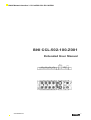
Balluff Network Interface / CC-Link BNI-CCL-502-100-Z001
BNI CCL-502-100-Z001
Extended User Manual
www.balluff.com
1
Balluff Network Interface / CC-Link BNI-CCL-502-100-Z001
1 Notes to the User
1.1
About this guide
1.2
Structure of the guide
1.3
Typographical Conventions
1.4
Symbols
1.5
Abbreviations
3
3
3
3
3
2 Safety
2.1
Intended Use
2.2
General Safety Notes
2.3
Meaning of the warnings
4
4
4
3 Connection
3.1
Connection overview
3.2
Mechanical connection
3.3
Supply voltage connection
3.4
CC-Link connection
3.5
Connecting sensors / actuators
3.6
Connecting IO-Link devices
5
6
6
7
7
7
4. Display
4.1
General
4.2
Default address
4.3
Display information
4.4
Menu structure
4.5
Edit mode
8
8
8
8
9
5. Communication interfaces, modes
5.1
CC-Link overview
5.2
CC-Link: cyclic and acyclic communication
5.3
IO-Link overview
10
11
11
6. Acyclic messaging
6.1
Overview
6.2
Message structure
6.3
Request/response data
13
13
14
7. Data mapping
7.1
Profile presets
7.2
Port configuration
7.3
RX and RY
7.4
RX and RY signal details
7.5
RWr and RWw
7.6
RWr and RWw signal details
17
17
18
20
21
24
8. Technical Data
8.1
Dimensions
8.2
Mechanical Data
8.3
Operating Conditions
8.4
Electrical Data
8.5
CC-Link Port
8.6
Function Indicators
24
24
24
24
25
25
9. Included Material
9.1
Included Material
27
Appendix
28
2
Balluff Network Interface / CC-Link BNI-CCL-502-100-Z001
1
Notes for the user
1.1 About this guide
This guide describes the Balluff CC-Link Field bus Module BNI CCL-… which enables
expanded communication down to the lowest level so as to provide improved process
optimizing and preventive maintenance. This module is IP67 protected and features a
rugged metal IP67 housing. The device is ideal for use in harsh industrial environments.
1.2 Structure of the guide
The Guide is organized so that the sections build on one another.
Section 2. Basic safety information.
Section 3: The main steps for installing the device.
Section 4: Technical data for the device.
…
The following typographical conventions are used in this guide.
1.3 Typographical
Conventions
Syntax
Numbers:
− Decimal numbers are shown without additional indicators (e.g. 123),
− Hexadecimal numbers are shown with additional indicator hex (e.g. 00hex)
Cross-references
Cross-references indicate where further information on the topic can be found ("see
Section 4 “).
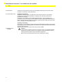
1.4 Symbols
Note, tip
This symbol indicates general notes.
Attention!
This symbol in connection with the word "Attention" warns of a possible hazardous
situation for the health of persons or for equipment damage. Disregard of these
warning notes may result in injury or damage to equipment.
Always observe the described measures for preventing this danger.
1.5 Abbreviations
www.balluff.com
BNI
CCL
EMC
FE
SIO
IOL
X
Y
Balluff Network Interface
CC-Link
Electromagnetic Compatibility
Function Ground
Standard Input/Output
IO-Link
Denotes an input
Denotes an output
3
Balluff Network Interface / CC-Link BNI-CCL-502-100-Z001
2
Safety
2.1 Intended Use
The BNI CCL-502-100-Z001 serves as a decentralized input/output and IO-Link master
module for connecting to a CC-Link network.
2.2 General Safety Notes
Installation and start up
Installation and start-up are to be performed only by trained personnel. Any damage
resulting from unauthorized manipulation or improper use voids the manufacturer’s
guarantee and warranty.
The device is an equipment in accordance with EMC Class A. Such equipment may
generate RF noise. The operator is responsible for taking the appropriate measures before
using. The device may be operated only using an approved power supply (see 0„Technical
Data“). Only approved cables may be used.
2.3 Meaning of the
warnings
Operations and testing
The operator is responsible for ensuring that local prevailing safety regulations are followed.
When defects and non-clearable faults in the device occur, take it out of service and secure
against unauthorized use.
Approved use is ensured only when the housing is fully installed.
Caution!
This symbol in connection with the word "Caution" warns of a possible hazardous
situation for the health of persons or for equipment damage. Disregard of these
warning notes may result in injury or damage to equipment.
Always observe the described measures for preventing this danger.
4
Balluff Network Interface / CC-Link BNI-CCL-502-100-Z001
3
Connection data
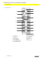
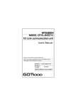
3.1 Connection Overview
1
2
16
3
15
4
14
13
12
5
11
6
10
7
9
8
1
1
2
3
4
5
6
7
8
9
www.balluff.com
Mounting hole
CC-Link Bus Input
Display
Power supply IN
Port4 : Standard I/O
Port5 : Standard I/O
Port6 : Standard I/O, IO-Link
Port7 : Standard I/O, IO-Link
Port3 : Standard I/O, IO-Link
10
11
12
13
14
15
16
Port2 : Standard I/O, IO-Link
Port1 : Standard I/O
Port0 : Standard I/O
Status LED
Power supply OUT
Label
CC-Link Bus Output
5
Balluff Network Interface / CC-Link BNI-CCL-502-100-Z001
3
Connection data
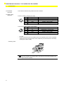
3.2 Mechanical
connection
The module is attached using 2 M6 screws and 2 washers.
3.3 Supply voltage
connection
Power In (7/8 Mini- Change 5 pin, male)
PIN
Signal
1
0V
2
0V
3
FE
4
+24V
5
+24V
Description
GND Actuator supply
GND Module- / sensor supply
Function Ground
Module- / sensor supply
Actuator supply
Power Out (7/8 Mini- Change, 5 pin, female)
PIN
Signal
1
0V
2
0V
3
FE
4
+24V
5
+24V
Description
GND Actuator supply
GND Module- / sensor supply
Function Ground
Module- / sensor supply
Actuator supply
−
−
−
24 V DC.
Provide sensor/bus power and actuator power from separate power sources if possible.
Total current <9A. The total current of all modules may not exceed 9A even when daisy
chaining the actuator supply.
Function ground
Note!
The FE connection from the housing to the machine must be low-impedance and
kept as short as possible.
6
Balluff Network Interface / CC-Link BNI-CCL-502-100-Z001
3
Connection data
3.4 CC-Link Connection
The CC-Link connection is made using the M12 sockets Bus In and Bus Out (A-coded).
Bus In: (M12, A-coded, male)
PIN
1
2
3
4
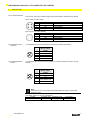
3.5 Connecting sensors /
actuators
Requirement
SLD
DB
DG
DA
Shield
B Line (white)
Ground (yellow)
A Line (blue)
Bus Out: (M12, A-coded, female)
PIN
Requirement
1
SLD
2
DB
3
DG
4
DA
Shield
B Line (white)
Ground (yellow)
A Line (blue)
Note
4 configurable SIO ports are provided for connecting actuators and sensors
PIN
1
2
3
4
5
3.6 Connecting IO-Link
devices
Note
Standard I/O-Port
M12, A coded,
female
+24V, 200mA
Input / Output 2A
0V
Input / Output 2A
FE
4 configurable SIO + IOL ports are provided for connecting actuators/ sensors / IO-Link
devices
PIN
1
2
3
4
5
IO-Link Port
M12, A coded,
female
+24V, 1.6A
Input / Output 2 A
0V
IO-Link/
Input / Output 1.6A
-
Note!
Unused I/O or IOL port sockets must be fitted with cover caps to ensure IP67
protection rating.
Connection options for the CC-Link Modules
Module
Standard I-Port Standard O-Port
BNI CCL-502-100-Z001
Max 16
Max 16
www.balluff.com
IO-Link Port
Max 4
7
Balluff Network Interface / CC-Link BNI-CCL-502-100-Z001
4
Display
4.1 General
The BNI CCL-502-100-Z001 serves as a decentralised input/output/IO-Link gateway module
for connecting to a CC-Link network. With the implemented display, the address, the
communication speed and the CCL mode preset are set directly on the BNI CCL-502-100Z001 devices.
4.2 Default settings
Address:
Communication speed:
CC-Link preset:
3
10Mbps
P1 (CCL Ver1.0; 3 Stations occupied)
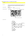
4.3 Display information
Symbol of locked state
Station address
156k 625k 2M5
5M 10M
Cursor for selecting the baud rate
4.4 Menu structure
Startup
screen
Timeout (10s<), or
Startup timeout (3s)
Addres &
BaudRate
long press (3s<) on
Press on
S
S
Edit values
Timeout (10s<), or
Press on
↑
long press (3s<) on
Press on
Press on
↑
Version
info
Press on
8
↑
S
Edit value
S
Balluff Network Interface / CC-Link BNI-CCL-502-100-Z001
4
Display
4.5 Edit mode
The BNI CCL-502-100-Z001 serves as a decentralised input/output and IO-L master module
for connecting to a CC-Link network. With the implemented display, the address, the
communication speed and the CCL mode preset is set directly on the BNI CCL-502-100Z001 devices.
-
push (<3s) on “↑ “ scroll to the next screen
pus on “↑ “
increment value by one (in edit mode)
long push on “↑” and hold it
increments value continuously (in edit
mode)
long push(>3s) on “S”
edit mode is activated, display information is
flashing
long push on “S”
leave edit mode and save the changes (in edit
mode)
push on “S”
change between editing Address or BaudRate (in
edit mode)
after 10 seconds without any key hit, the changes are discarded and display
returns to normal displaying mode
Additional features:
“Lock function” by PLC, edit mode is not accessible
“Free controllable” LEDs by PLC
The Lock function:
when the Display Lock bit is set, user is unable to modify settings via the display
buttons
in locked state, if user wants to enter edit mode, instead, the lock symbol is going
to be displayed
after clearing the Display Lock bit, the normal display screen is restored
www.balluff.com
9
Balluff Network Interface / CC-Link BNI-CCL-502-100-Z001
5
Communication interfaces and modes
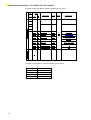
5.1 CC-Link overview
The BNI CCL-502-100-Z001 module supports both CC-Link Ver1 and CC-Link Ver2
communication forms. Ver2 is capable of transmitting greater amount of data using multiple
scan cycles (extended cycles).
Bus configuration is described by slave address, number of occupied stations,
communication speed and -in case of Ver2 communication- number of extended cycles. All
of these are adjustable via the interactive display.
Version 2
Maximum number of link
(Data volume)
1 station occupied
Number
of links
per
machine
(Data
Volume)
2 stations occupied
3 stations occupied
4 stations occupied
Version 1
RX/RY: 8192 bits
RX/RY: 2048 bits
RWw/RWr: 2048 words
RWw/RWr: 256 words
RX/RY: 32 to 128 bits
RX/RY: 32 bits
RWw/RWr: 8 to 32 words
RWw/RWr: 4 words
RX/RY: 96 to 384 bits
RX/RY: 64 bits
RWw/RWr: 16 to 64 words
RWw/RWr: 8 words
RX/RY: 160 to 640 bits
RX/RY: 96 bits
RWw/RWr: 24 to 96 words
RWw/RWr: 12 words
RX/RY: 224 to 896 bits
RX/RY: 128 bits
RWw/RWr: 32 to 128 words
RWw/RWr: 16 words
Number of occupied stations
per machine
1 to 4
1 to 4
Extended cyclic setting
2x, 4x, 8x
None
2x
Settings
4x
Settings
8x
Settings
1 station occupied
2 stations ocupied
3 stations occupied
RX/RY: 32 bits
RWw/RWr: 8 words
RX/RY: 64 bits
RWw/RWr: 16
words
RX/RY: 128 bits
RWw/RWr: 32
words
RX/RY: 96 bits
RWw/RWr: 16
words
RX/RY: 192 bits
RWw/RWr: 32
words
RX/RY: 384 bits
RWw/RWr: 64
words
RX/RY: 160 bits
RWw/RWr: 24
words
RX/RY: 320 bits
RWw/RWr: 48
words
RX/RY: 640 bits
RWw/RWr: 96
words
4 stations occupied
RX/RY: 224 bits
RWw/RWr: 32 words
RX/RY: 448 bits
RWw/RWr: 64 words
RX/RY: 896 bits
RWw/RWr: 128 words
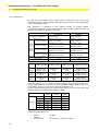
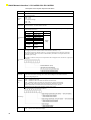
There are [Version, Num of stations occupied, Extended Cycle] settings stored in the
module, called presets, P1 to P5. User can not change Num of stations occupied, Version or
Cycle Settings one-by one. User can only select which Preset to use.
However, between limits given by the current Preset selected, user can change some data
mapping settings. See section “Data mapping” for details.
Presets
CC-Link
Version
Stations
occupied
Extended
Cycles
P0
Ver1
2
-
P1
Ver1
3
-
P2
Ver1
4
-
P3
Ver2
3
2x
P4
Ver2
3
4x
P5
Ver2
3
8x
Default factory bus settings are:
−
−
−
10
Speed:
Address:
CC-Link preset:
10 Mbps
3
P1 (Version1, 3 Stations occupied,-)
Balluff Network Interface / CC-Link BNI-CCL-502-100-Z001
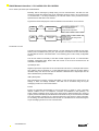
5.2 CC-Link: cyclic and acyclic communication
Basically, data is exchanged cyclically during CC-Link communication. The BNI CCL-502100-Z001 module also features the acyclic messaging protocol, which is an on-request type
of communication. It is always initiated by the CC-Link master and it provides access to
special function data areas of the module.
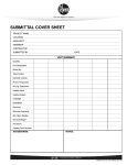
Figure below shows the purpose of the two different communications on CC-Link bus.
CCL
Master
CCL
Master
cyclic
exchange
acyclic
messaging
BNI CCL-502100-Z001
Standard Inputs&Outputs
IO-L Inputs&Outputs,
Diagnostic&Configuration
BNI CCL-502100-Z001
Module Info R
Advanced module settings R&W
ISDU data R&W
Event data R
5.3 IO-Link overview
The BNI CCL-502-100-Z001 module features 4 IO-Link master ports (called IO-Link ports).
When a port is enabled as IOL port, pin1, pin4 and pin3 are used for IO-Link communication
as described in section “Connection data”. The remaining pin2 is still a freely configurable
SIO pin.
The IO-Link master functionality of the BNI module supports IO-Link 1.0 communication
standard. Input/Output data, SPDU data and Events of the IO-Link connections are all
available in the BNI module.
Input/Output data:
Regular input and/or output data of the connected IO-Link slave. For example data used to
turn outputs of the IO-Link slave on, or data indicating the input status of the slave. Data is
refreshed every time the CC-Link data is refreshed. Maximal size of Input/Output IO-Link
data is determined by module settings.
ISDU (SPDU) data:
Data transferred on-request, providing description of the IO-Link slave and access to its
settings -if there are settings available-. This data can be accessed using the acyclic
messaging mode of CC-Link communication.
Events:
Events are generated automatically by the IO-Link slave or master in case a specially
defined condition occurs. For example a connection is established or lost (master). Low
supply voltage is detected, short circuit on the slave output is detected (slave) etc. Events of
a given port are described by EventMode and EventCode. Every IO-Link channel of the BNI
CCL-502-100-Z001 module has an 4 elements deep FIFO type queue to store event data.
So at reading, the oldest stored event data is read out. This data can be accessed using the
acyclic messaging mode of CC-Link communication.
www.balluff.com
11
Balluff Network Interface / CC-Link BNI-CCL-502-100-Z001
Example of ISDU data (BNI IOL-722/724-000-K023 IO-Link device):
DPP
Parameter Data
Identification Data
Index
SPDU
Index
SubInde
x
0x10
0
Vendor name
7 Byte
0x11
0
Vendor text
15 Byte
0x12
0
Product name
20 Byte
0x13
0
Product ID
7 Byte
0x14
0
Product text
22 Byte
0x16
0
Hardware Revision
1 Byte
1
0x17
0
Firmware Revision
23 Byte
1.0
Object name
Length
Range
Default value
BALLUFF
read
only
www.balluff.com
BNI IOL-722-000-K023
BNI IOL-724-000-K023
BNI 004C
BNI 004E
Hobbit current output
Hobbit voltage output
-
Example of Events (BNI IOL-722/724-000-K023 IO-Link device):
12
Event Mode
Event Code (H+L)
Appears/Coming
Supply voltage low
0xC0
0x0010
Disappears/Going
Supply voltage low
0x80
0x0010
Balluff Network Interface / CC-Link BNI-CCL-502-100-Z001
6
Acyclic messaging
6.1 Overview
Acyclic messaging is used to reach special data of the BNI CCL-502-100-Z001 module and
the connected IO-Link devices. These special function data areas are organized by using so
called channels.
The following channels are supported by the BNI CCL-502-100-Z001:
− Module info: 0x10
− IO-Link channel settings: 0x20…0x23
− IO-Link channel data: ISDU and event data 0x30…0x31
6.2 Message structure
For messaging, some data area of the CC-Link communication area is reserved, called
“Message transmission area”. Message block structure is like the following:
Read Request
Block Number
Write Request
L
Subcommand Type H
L
H
Division number
L
Division number
L
Data size
H
Data size
H
Request data
Request data
Sum check
Sum check
Read Response
Block Number
Write Response
L
Subcommand Type H
Return status
Division number
Data size
www.balluff.com
Block Number
Subcommand Type
L
H
L
H
Block Number
Subcommand Type
Return status
Division number
Data size
Response data
Response data
Sum check
Sum check
L
H
L
H
L
H
13
Balluff Network Interface / CC-Link BNI-CCL-502-100-Z001
6.3 Request/response data
The following table shows what kind of data is transferred in the different request/response
data blocks.
Gateway identification:
Byte No.
Gateway
Item
Identification data
Byte 0
Channel
0x10
Byte 1
Length
0-64
Byte 2
Control/
Status
Read/-
Byte 3
Index
Index
Message
data
Request/
Response
Data
(length =
0-64 bytes)
Byte 4
Byte 5
Byte 6
Byte 7
Byte 8
Byte 9
Byte 10
Byte 11
Byte 12
to
Byte 252
IO-Link channel settings:
Byte No.
IO-Link Channel
Item
Process data size
Validation data
Byte 0
Channel
0x20
0x21
Byte 1
Length
0/8
0/22
Byte 2
Control/
Status
Read/Write
Read/Write
Byte 3
Port
Number
Reserved
(Fixed to 0)
IO-Link Channel 1
Channel Number
Byte 4
Validation type
Byte 6
IO-Link Channel 3
Reserved
(Fixed to 0)
Vendor ID1
Byte 7
IO-Link Channel 4
Vendor ID2
IO-Link Channel 2
Byte 5
Device ID1
Byte 8
Device ID2
Byte 9
Byte 10
Byte 11
Byte 12
to
Byte 27
Message
data
Device ID3
Unused
Reserved
(Fixed to 0)
Serial Number1
to
Serial Number16
to
Byte 252
14
Unused
Balluff Network Interface / CC-Link BNI-CCL-502-100-Z001
IO-Link channel settings:
Byte No.
IO-Link channel
Item
Data storage
Data storage clear
Byte 0
Channel
0x22
0x23
Byte 1
Length
0/8
8
Byte 4
Read/Write
Reserved
(Fixed to 0)
IO-Link Channel 1
-/Write
Reserved
(Fixed to 0)
IO-Link Channel 1
Byte 5
IO-Link Channel 2
IO-Link Channel 2
Byte 6
IO-Link Channel 3
IO-Link Channel 3
Byte 7
IO-Link Channel 4
IO-Link Channel 4
Unused
Unused
Byte 2
Byte 3
Control/
Status
Port
Number
Message
data
to
Byte 252
IO-Link channel data:
Byte No.
Byte 0
Byte 1
Byte 2
Byte 3
ISDU
Event data
Channel
0x30
0x31
Length
0-232
0/4
Read/Write
Read/-
Channel Number
Index L
Channel Number
Event Qualifier
Index H
Reserved
(Fixed to 0)
EventCode L
Control/
Status
Port
Number
Byte 4
Byte 5
Byte 6
Byte 7
Byte 8
to
Byte 252
www.balluff.com
IO-Link channel
Item
Subindex
Message
data
Reserved
(Fixed to 0)
EventCode H
Request/Response
Data
(length = 0-232 bytes)
Unused
15
Balluff Network Interface / CC-Link BNI-CCL-502-100-Z001
Description of the request/ response data items:
Item
Description
Channel
Channel selects the access area
Control/
status
For request message:
0x02 = write
0x03 = read
For response message:
0x00 = OK
0xF0 = error
Index/
Channel No.
Index = address of the gateway identification data (for details refer to the next table)
Channel Number = IO-Link Channel number
Identification data of the gateway, for details refer to the following “Description of the gateway
identification data index”
Identification
data
Index
0x00-0x0A
0x10
0x11
0x12
0x13
0x14
0x15
0x16
0x17
Object Name
Not used
Vendor name
Vendor text
Product name
Product code
Product text
Not used
Hardware
Revision
Firmware
Revision
Type
n.a.
Read
Only
The process data size setting for each IO-Link channel can be read and written. The value shows
the mapped process data size for each IO-Link channel in Words (0 - 16).
The sum of all IO-Link channel’s data size + message transmission area must not exceed the
maximum available Word area, which is determined by the number of occupied stations and
extended cyclic setting.
Process data
size
ISDU
Event data
Validation
data
The order in which IO-Link process and parameter data is mapped can be set with bit 7 (high byte/
low byte).
Reading/ Writing IO-Link parameter data
The event data (Event qualifier and event code) of a pending event indicated
by the IO-Link channel event flag can be read. After reading the event data the IOLink
port event flag changes to 0.
IO-Link device validation. The validation type is defined as follows:
0x00 = validation deactivated
0x01 = validation of IO-Link Vendor ID and IO-Link Device ID
0x02 = validation of IO-Link Vendor ID, IO-Link Device ID and serial number
Depending on the configuration of the IO-Link device validation the connected
device’s information is verified and the result indicated by the port valid bit.
Configuration of the data storage function of the IO-Link master.
The configuration byte is defined as follows:
Data storage
Data storage
clear
16
IO-Link master data storage clear command:
0x55 = Clear IO-Link master data storage
Balluff Network Interface / CC-Link BNI-CCL-502-100-Z001
7
Data mapping
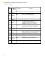
7.1 Profile Presets
Depending on the selected profile, the number of occupied stations, version and extended
cyclic setting are set. These determine the data amount available for the device, so a given
profile determines the number of data pro IO-Link channel too.
The listed process data size of each IO-Link channel is the default setting of the selected
profile.
Profile
No.
Number of
IO-Link
Channels
0
1
IO-Link process data size
for each IO-Link Channel
Input process
data size
[Bytes]
Output
process data
size
[Bytes]
Number of
occupied stations
Extended cyclic
setting
4
2
2
2
-
4
4
4
3
-
2
4
6
6
4
-
3
4
10
10
3
2
4
4
20
20
3
4
5
4
32
32
3
8
7.2 Port Configuration
Port0:
Input(X)/Output(Y) 0,1
Port4:
Input(X)/Output(Y) 8,9
Port1:
Input(X)/Output(Y) 2,3
Port5:
Input(X)/Output(Y) A,B
Port2:
Input(X)/Output(Y) 4,5
IO-L Channel 1
Port6:
Input(X)/Output(Y) C,D
IO-L Channel 2
Port3:
Input(X)/Output(Y) 6,7
IO-L Channel 3
www.balluff.com
Port7:
Input(X)/Output(Y) C,D
IO-L Channel 4
17
Balluff Network Interface / CC-Link BNI-CCL-502-100-Z001
7.3 RX and RY
Device No.
When 2 When 3 or 4
stations
stations are
are
occupied
occupied
RXm0
RXm1
RXm2
RXm3
RXm4
RXm5
RXm6
RXm7
RXm8
RXm9
RXmA
RXmB
RXmC
RXmD
RXmE
RXmF
RX(m+1)0
RX(m+1)1
RX(m+1)2
RX(m+1)3
RX(m+1)4
RX(m+1)5
RX(m+1)6
RX(m+1)7
RX(m+1)8
RX(m+1)9
RX(m+1)A
RX(m+1)B
RX(m+1)C
RX(m+1)D
RX(m+1)E
RX(m+1)F
RX(m+2)0
RX(m+2)1
RX(m+2)2
RX(m+2)3
RX(m+2)4
RX(m+2)5
RX(m+2)6
RX(m+2)7
RXm0
RXm1
RXm2
RXm3
RXm4
RXm5
RXm6
RXm7
RXm8
RXm9
RXmA
RXmB
RXmC
RXmD
RXmE
RXmF
RX(m+1)0
RX(m+1)1
RX(m+1)2
RX(m+1)3
RX(m+1)4
RX(m+1)5
RX(m+1)6
RX(m+1)7
RX(m+1)8
RX(m+1)9
RX(m+1)A
RX(m+1)B
RX(m+1)C
RX(m+1)D
RX(m+1)E
RX(m+1)F
RX(m+2)0
RX(m+2)1
RX(m+2)2
RX(m+2)3
RX(m+2)4
RX(m+2)5
RX(m+2)6
RX(m+2)7
RX(m+2)8
RX(m+2)9
RX(m+2)A
RX(m+2)B
RX(m+2)C
RX(m+2)D
RX(m+2)E
RX(m+2)F
18
Slave
Master
Signal name
Input 0, Port0 pin 4
Input 1 , Port1 pin 2
Input 2 , Port2 pin 4
Input 3 , Port3 pin 2
Input 4 , Port4 pin 4
Input 5 , Port5 pin 2
Input 6 , Port6 pin 4
Input 7 , Port7 pin 2
Input 8 , Port8 pin 4
Input 9 , Port9 pin 2
Input A , PortA pin4
Input B , PortB pin 2
Input C , PortC pin 4
Input D , PortD pin 2
Input E , PortE pin 4
Input F , PortF pin 2
Diagnostic Input / Output 0
Diagnostic Input / Output 1
Diagnostic Input / Output 2
Diagnostic Input / Output 3
Diagnostic Input / Output 4
Diagnostic Input / Output 5
Diagnostic Input / Output 6
Diagnostic Input / Output 7
Diagnostic Input / Output 8
Diagnostic Input / Output 9
Diagnostic Input / Output A
Diagnostic Input / Output B
Diagnostic Input / Output C
Diagnostic Input / Output D
Diagnostic Input / Output E
Diagnostic Input / Output F
Diagnostic port 0
Diagnostic port 1
Diagnostic port 2
Diagnostic port 3
Diagnostic port 4
Diagnostic port 5
Diagnostic port 6
Diagnostic port 7
US undervoltage
UA undervoltage
Unused
Device No.
When 2 When 3 or
stations 4 stations
are
are
occupied occupied
RYm0
RYm1
RYm2
RYm3
RYm4
RYm5
RYm6
RYm7
RYm8
RYm9
RYmA
RYmB
RYmC
RYmD
RYmE
RYmF
RY(m+1)0
RY(m+1)1
RY(m+1)2
RY(m+1)3
RY(m+1)4
RY(m+1)5
RY(m+1)6
RY(m+1)7
RY(m+1)8
RY(m+1)9
RY(m+1)A
RY(m+1)B
RY(m+1)C
RY(m+1)D
RY(m+1)E
RY(m+1)F
RY(m+2)0
RY(m+2)1
RY(m+2)2
RY(m+2)3
RY(m+2)4
RY(m+2)5
RY(m+2)6
RY(m+2)7
RYm0
RYm1
RYm2
RYm3
RYm4
RYm5
RYm6
RYm7
RYm8
RYm9
RYmA
RYmB
RYmC
RYmD
RYmE
RYmF
RY(m+1)0
RY(m+1)1
RY(m+1)2
RY(m+1)3
RY(m+1)4
RY(m+1)5
RY(m+1)6
RY(m+1)7
RY(m+1)8
RY(m+1)9
RY(m+1)A
RY(m+1)B
RY(m+1)C
RY(m+1)D
RY(m+1)E
RY(m+1)F
RY(m+2)0
RY(m+2)1
RY(m+2)2
RY(m+2)3
RY(m+2)4
RY(m+2)5
RY(m+2)6
RY(m+2)7
RY(m+2)8
RY(m+2)9
RY(m+2)A
RY(m+2)B
RY(m+2)C
RY(m+2)D
RY(m+2)E
RY(m+2)F
Master
Slave
Signal name
Output 0 , Port0 pin 4
Output 1 , Port1 pin 2
Output 2 , Port2 pin 4
Output 3 , Port3 pin 2
Output 4 , Port4 pin 4
Output 5 , Port5 pin 2
Output 6 , Port6 pin 4
Output 7 , Port7 pin 2
Output 8 , Port8 pin 4
Output 9 , Port9 pin 2
Output A , PortA pin4
Output B , PortB pin 2
Output C , PortC pin 4
Output D , PortD pin 2
Output E , PortE pin 4
Output F , PortF pin 2
Port direction Input / Output 0
Port direction Input / Output 1
Port direction Input / Output 2
Port direction Input / Output 3
Port direction Input / Output 4
Port direction Input / Output 5
Port direction Input / Output 6
Port direction Input / Output 7
Port direction Input / Output 8
Port direction Input / Output 9
Port direction Input / Output A
Port direction Input / Output B
Port direction Input / Output C
Port direction Input / Output D
Port direction Input / Output E
Port direction Input / Output F
Display Red LED
Display Green LED
Display Lock
Unused
Balluff Network Interface / CC-Link BNI-CCL-502-100-Z001
Device No.
When 2
When 3 or 4
stations are stations are
occupied
occupied
Slave
Master
Device No.
Master
Slave
Signal name
When 2
stations
are
occupied
When 3 or 4
stations are
occupied
Signal name
RX(m+2)8
RX(m+2)9
RX(m+3)0
RX(m+3)1
IO-Link Channel 1 valid
IO-Link Channel 2 valid
RY(m+2)8
RY(m+2)9
RY(m+3)0
RY(m+3)1
IO-Link Channel 1 enable
IO-Link Channel 2 enable
RX(m+2)A
RX(m+3)2
IO-Link Channel 3 valid
RY(m+2)A
RY(m+3)2
IO-Link Channel 3 enable
RX(m+2)B
RX(m+3)3
IO-Link Channel 4 valid
RY(m+2)B
RY(m+3)3
IO-Link Channel 4 enable
RX(m+3)4
RX(m+3)5
RX(m+3)6
RY(m+3)4
RY(m+3)5
Reserved
RY(m+3)6
RX(m+3)7
Reserved
RY(m+3)7
IO-Link Channel 1 event clear
RX(m+2)C
RX(m+3)8
IO-Link Channel 1 event flag
RY(m+2)C
RY(m+3)8
RX(m+2)D
RX(m+3)9
IO-Link Channel 2 event flag
RY(m+2)D
RY(m+3)9
IO-Link Channel 2 event clear
RY(m+3)A
IO-Link Channel 3 event clear
RY(m+3)B
IO-Link Channel 4 event clear
RX(m+2)E
RX(m+3)A
IO-Link Channel 3 event flag
RY(m+2)E
RX(m+2)F
RX(m+3)B
IO-Link Channel 4 event flag
RY(m+2)F
RX(m+3)C
RX(m+3)D
RX(m+3)E
RY(m+3)C
RY(m+3)D
Reserved
RY(m+3)E
RX(m+3)F
to
Reserved
RY(m+3)F
Unused
RX(m+3)0
RX(m+n)0
RX(m+3)1
RX(m+n)1
RX(m+3)2
RX(m+n)2
RX(m+3)3
RX(m+n)3
RX(m+3)4
RX(m+n)4
RX(m+3)5
RX(m+n)5
RX(m+3)6
RX(m+n)6
RX(m+3)7
RX(m+n)7
RX(m+3)8
RX(m+n)8
RX(m+3)9
RX(m+n)9
RX(m+3)A
RX(m+n)A
Error state flag
RX(m+3)B
RX(m+n)B
RX(m+3)C
RX(m+n)C
Remote ready flag
Message transmission
RX(m+3)D
RX(m+n)D
Message handshake flag
RX(m+3)E
RX(m+n)E
RX(m+3)F
RX(m+n)F
to
Unused
RY(m+3)0
RY(m+n)0
RY(m+3)1
RY(m+n)1
RY(m+3)2
RY(m+n)2
RY(m+3)3
RY(m+n)3
RY(m+3)4
RY(m+n)4
RY(m+3)5
RY(m+n)5
RY(m+3)6
RY(m+n)6
RY(m+3)7
RY(m+n)7
RY(m+3)8
RY(m+n)8
Initial data processing completion flag
Initial data setting completion flag RY(m+3)9
RY(m+n)9
Initial data setting request flag
RY(m+3)A
RY(m+n)A
Error reset request flag
RY(m+3)B
RY(m+n)B
Reserved
RY(m+3)C
RY(m+n)C
Message transmission request flag
RY(m+3)D
RY(m+n)D
Message handshake flag
RY(m+3)E
RY(m+n)E
Reserved
RY(m+3)F
RY(m+n)F
Reserved
Message transmission size
Reserved
Initial data processing request
Reserved
Reserved
m: Address assigned to the master module by the station number setting
n: Dependent on the number of occupied stations and extended cyclic setting:
− 3 stations + no extended cyclic setting: 5
− 4 stations + no extended cyclic setting: 7
− 3 stations + 2 extended cyclic setting: 9
− 3 stations + 4 extended cyclic setting: 13
− 3 stations + 8 extended cyclic setting: 27
− 4 stations + 8 extended cyclic setting: 37
www.balluff.com
19
Balluff Network Interface / CC-Link BNI-CCL-502-100-Z001
7.4 RX and RY signal details
Device No.
When 2
When 3 or 4
stations
stations
are
are occupied
occupied
RXm0
to
RXmF
20
RXm0
to
RXmF
Signal name
Description
Input 0 – F
Digital Input signal 0 – F
RX(m+1)0 RX(m+1)0
to
to
RX(m+1)F RX(m+1)F
Diagnostic input/
output
Error on the corresponding input/ output line
e.g. over-current, short-circuit, output override
RX(m+2)0 RX(m+2)0
to
to
RX(m+2)7 RX(m+2)7
RX(m+2)8
Diagnostic port
Error on the corresponding port’s power supply line
e.g. over-current, short-circuit
US undervoltage
US voltage is low
RX(m+2)9
UA undervoltage
UA voltage is low
RX(m+2)8 RX(m+3)0
to
to
RX(m+2) RX(m+3)7
B
IO-Link channel
valid
In IO-Link mode this signal = 1 if an IO-Link device is connected,
the IO-Link communication is operating and the
IO-Link device’s PDinvalid flag is not set. Further if IO-Link
device validation is activated the result of the validation is
indicated by this bit.
RX(m+2) RX(m+4)8
C
to
to
RX(m+4)F
RX(m+2)F
IO-Link channel
event flag
Event from the connected IO-Link device.
After reading out all event information via message transmission
function the IO-Link channel event flag clears automatically.
RYm0
to
RYmF
Output 0 – F
Digital Output signal 0 – F
RY(m+1)0 RY(m+1)0
to
to
RY(m+1)F RY(m+1)F
Port direction
When setting the port direction bit = 0 the corresponding signal line is
operating as a digital input. In the case that the port direction bit = 1
the corresponding signal line is operating as a digital output.
RY(m+2)0 RY(m+2)0
Display Red LED
Setting bit to 1 turns on the red LEDs of the display
RY(m+2)1 RY(m+2)1
Display Green LED
Setting bit to 1 turns on the green LEDs of the display
RY(m+2)3 RY(m+2)3
Display LOCK
When set to 1, Preset, Address and Speed settings of the module
are locked
RY(m+2)8 RY(m+3)0
to
to
RY(m+2) RY(m+3)7
B
IO-Link channel
enable
By setting the IO-Link channel enable bit = 1
the corresponding port is operating in IO-Link mode
RY(m+2) RY(m+3)8
C
to
to
RY(m+3)F
RY(m+2)F
IO-Link channel
event clear
By setting the IO-Link channel event clear bit = 1 all events of the
corresponding IO-Link channel are cleared. By keeping it set to 1
all new events are automatically cleared.
RYm0
to
RYmF
Balluff Network Interface / CC-Link BNI-CCL-502-100-Z001
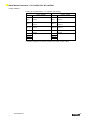
7.5 RWr and RWw
Profile 0 [2 occupied stations + no extended cyclic setting]
Slave
Address
Master
Description
Master
Address
Slave
Description
RWrn
Input process data IO-Link
Channel1
RWwn
Output process data IO-Link
Channel1
RWrn+1
Input process data IO-Link
Channel 2
RWwn+1
Output process data IO-Link
Channel 2
RWrn+2
Input process data IO-Link
Channel 3
RWwn+2
Output process data IO-Link
Channel 3
RWrn+3
Input process data IO-Link
Channel4
RWwn+3
Output process data IO-Link
Channel4
RWrn+4 Message transmission area
RWrn+5
RWrn+6
RWrn+7
RWwn+4 Message transmission area
RWwn+5
RWwn+6
RWwn+7
n: Address assigned to the master module by the station number setting
www.balluff.com
21
Balluff Network Interface / CC-Link BNI-CCL-502-100-Z001
Profile 1 [3 occupied stations + no extended cyclic setting]
Slave
Master
Master
Slave
Address
Description
RWrn
Input process data IO-Link
RWrn+1 Channel1
Address
Description
RWwn
Output process data IO-Link
RWwn+1 Channel1
RWrn+2 Input process data IO-Link
RWrn+3 Channel 2
RWwn+2 Output process data IO-Link
RWwn+3 Channel 2
RWrn+4 Input process data IO-Link
RWrn+5 Channel 3
RWwn+4 Output process data IO-Link
RWwn+5 Channel 3
RWrn+6 Input process data IO-Link
RWrn+7 Channel4
RWrn+8 Message transmission area
RWrn+9
RWrn+A
RWrn+B
RWwn+6 Output process data IO-Link
RWwn+7 Channel4
RWwn+8 Message transmission area
RWwn+9
RWwn+A
RWwn+B
n: Address assigned to the master module by the station number setting
Profile 2 [4 occupied stations + no extended cyclic setting]
Slave
Master
Address
Description
RWrn
Input process data IO-Link
RWrn+1
Channel1
RWrn+2
RWrn+3 Input process data IO-Link
RWrn+4 Channel 2
RWrn+5
RWrn+6 Input process data IO-Link
RWrn+7 Channel 3
RWrn+8
RWrn+9 Input process data IO-Link
RWrn+A Channel 4
RWrn+B
RWrn+C Message transmission area
RWrn+D
RWrn+E
RWrn+F
Master
Address
RWwn
RWwn+1
RWwn+2
RWwn+3
RWwn+4
RWwn+5
RWwn+6
RWwn+7
RWwn+8
RWwn+9
RWwn+A
RWwn+B
RWwn+C
RWwn+D
RWwn+E
RWwn+F
Slave
Description
Output process data IO-Link
Channel1
Output process data IO-Link
Channel 2
Output process data IO-Link
Channel 3
Output process data IO-Link
Channel 4
Message transmission area
n: Address assigned to the master module by the station number setting
22
Balluff Network Interface / CC-Link BNI-CCL-502-100-Z001
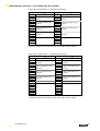
Profile 3 [3 occupied stations + 2 extended cyclic setting]
Slave
Address
RWrn
to
RWrn+4
RWrn+5
to
RWrn+9
RWrn+A
to
RWrn+E
RWrn+F
to
RWrn+13
RWrn+14
RWrn+15
RWrn+16
RWrn+17
Master
Description
Input process data IO-Link
Channel1
Input process data IO-Link
Channel 2
Input process data IO-Link
Channel 3
Input process data IO-Link
Channel 4
Message transmission area
Master
Address
RWwn
to
RWwn+4
RWwn+5
to
RWwn+9
RWwn+A
to
RWwn+E
RWwn+F
to
RWwn+1
3
RWwn+1
4
RWwn+1
5
RWwn+1
6
RWwn+1
7
Slave
Description
Output process data IO-Link
Channel1
Output process data IO-Link
Channel 2
Output process data IO-Link
Channel 3
Output process data IO-Link
Channel 4
Message transmission area
n: Address assigned to the master module by the station number setting
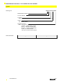
Profile 4 [3 occupied stations + 4 extended cyclic setting]
Slave
Master
Address
Description
RWrn
Input process data IO-Link
to
Channel1
RWrn+9
RWrn+A Input process data IO-Link
to
Channel 2
RWrn+13
RWrn+14 Input process data IO-Link
to
Channel 3
RWrn+1D
RWrn+1E Input process data IO-Link
to
Channel 4
RWrn+27
RWrn+28 Unused
RWrn+29 Message transmission area
RWrn+2A
RWrn+2B
RWrn+2C
RWrn+2D
RWrn+2E
RWrn+2F
Master
Address
RWwn
to
RWwn+9
RWwn+A
to
RWwn+13
RWwn+14
to
RWwn+1D
RWwn+1E
to
RWwn+27
RWwn+28
RWwn+29
RWwn+2A
RWwn+2B
RWwn+2C
RWwn+2D
RWwn+2E
RWwn+2F
Slave
Description
Output process data IO-Link
Channel1
Output process data IO-Link
Channel 2
Output process data IO-Link
Channel 3
Output process data IO-Link
Channel 4
Unused
Message transmission area
n: Address assigned to the master module by the station number setting
www.balluff.com
23
Balluff Network Interface / CC-Link BNI-CCL-502-100-Z001
Profile 5 [3 occupied stations + 8 extended cyclic setting]
Address
RWrn
to
RWrn+F
RWrn+10
to
RWrn+1F
RWrn+20
to
RWrn+2F
RWrn+30
to
RWrn+3F
RWrn+40
to
RWrn+58
RWrn+59
RWrn+5A
RWrn+5B
RWrn+5C
RWrn+5D
RWrn+5E
RWrn+5F
Slave
Master
Description
Input process data IO-Link
Channel1
Input process data IO-Link
Channel 2
Input process data IO-Link
Channel 3
Input process data IO-Link
Channel 4
Unused
Message transmission area
Address
RWwn
to
RWwn+F
RWwn+10
to
RWwn+1F
RWwn+20
to
RWwn+2F
RWwn+30
to
RWwn+3F
RWwn+40
to
RWwn+58
RWwn+59
RWwn+5A
RWwn+5B
RWwn+5C
RWwn+5D
RWwn+5E
RWwn+5F
Master
Slave
Description
Output process data IO-Link
Channel1
Output process data IO-Link
Channel 2
Output process data IO-Link
Channel 3
Output process data IO-Link
Channel 4
Unused
Message transmission area
n: Address assigned to the master module by the station number setting
7.6 RWr and RWw signal details
Process data in IO-Link mode of the specified port.
The size of the process data area is set by selecting one of the default profiles (1-10) or by
programming the gateway via the message transmission function. Input and output process
data areas of one IO-Link channel have both the same size.
The IO-Link data is mapped in the format shown below if high byte/ low byte swapping is
enabled:
High Byte
Low Byte
RWn
Address
Byte 0
Byte 1
RWn+1
Byte 2
Byte 3
to
RWn+15
To
To
Byte 30
Byte 31
The IO-Link data is mapped in the format shown below if high byte/ low byte swapping is
disabled:
High Byte
Low Byte
RWn
Address
Byte 1
Byte 0
RWn+1
Byte 3
Byte 2
to
RWn+15
to
to
Byte 31
Byte 30
Message transmission area:
The message transmission area is used for the acyclic message transmission function,
described in section 6.
High byte/low byte swapping also affects ISDU data.
24
Balluff Network Interface / CC-Link BNI-CCL-502-100-Z001
8
Technical Data
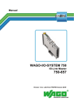
8.1 Dimensions
8.2 Mechanical data
8.3 Operating conditions
8.4 Electrical data
www.balluff.com
Housing material
Die-case zinc, matte nickel plated
Enclosure rating per IEC 60529
IP 67 (only when plugged-in and threaded-in)
Supply voltage
7/8” 5-pin male and female
Input ports / Output ports
M12, A coded (8 x female)
Dimensions (W x H x D in mm)
68 x 224 x 37.9
Mounting type
2-hole screw mount
Ground strap attachment
M4
Weight
Approx. 580gr.
Operating temperature Ta
Storage temperature
-5 °C … 70 °C
-25 C … 70 °C
EMC
- EN 61000-4-2/3/4/5/6
- EN 55011
- Severity level 4A/3A/4B/2A/3A
- Gr.1, CL. A
Shock / vibration
EN 60068-2-6, EN 60068-2-27
EN 60068-2-29, EN 60068-2-64
Supply voltage
18…30.2 V DC, per EN 61131-2
Ripple
<1%
Input current at 24 V
100 mA @ 24V
25
Balluff Network Interface / CC-Link BNI-CCL-502-100-Z001
8
Technical Data
8.5 CC-Link Port
CC-Link port
EIA RS485 compatible
Connection for CC-Link port
M12, A coded
Cable type
CC-Link dedicated cable (shielded 3-core
twisted pair cable)
Data transmission rate
10M / 5M / 2,5M / 625k / 156kbps
Max. cable length
up to 1200m (by 156kbps)
Supported modes
CC-Link Ver1 and CC-Link Ver2
Number of occupied stations
2 to 4 station
Extended cycle settings (Ver2)
2x, 4x, 8x
Station type
Remote device station
8.6 Function Indicators
LED 2-9, Status LED
Port/Pin LED: status of input/output/IOL
ports
Status LED
LED
LED 1
LED 2
LED 6
LED 7
Indicator
Green / Red
Green / Red
Green / Off
Red flashing
Red
Off
Function
US Power supply OK / undervoltage
UA Power supply OK / undervoltage
Bus connection status
CC-Link version error / Module settings have been changed
Communication error
Normal communication
LED indicators
input ports
Each M12 Port (digital input/output, IO-Link) is assigned two 2-color LEDs which indicate
the configuration or operating states.
LED
Function LED Pin 2 / Pin 4
Off
Input signal = 0
Yellow Input signal = 1
Red
Input signal = SC Short circuit*
LED indicators
output ports
LED
Off
Yellow
Red
26
Function LED Pin 2 / Pin 4
Output signal = 0
Output signal = 1
Output signal = Override / Overload
Balluff Network Interface / CC-Link BNI-CCL-502-100-Z001
LED indicators
IO-Link channels
LED
Off
Green
flashing
Green
Red flashing
Red
www.balluff.com
Function LED Pin 4
IOL port not enabled
No IO-Link communication
IO-Link connection established
Validation failed
Short-circuit
27
Balluff Network Interface / CC-Link BNI-CCL-502-100-Z001
9
Included Material
9.1 Included Material
28
The BNI CCL consists of the following components:
•
IO-block
•
4 blind plugs M12
•
Ground strap
•
Screw M4x6
•
20 labels
•
Short guide
Balluff Network Interface / CC-Link BNI-CCL-502-100-Z001
Appendix
BNI CCL-502-100-Z001
Ordering code
Balluff Network Interface
CC-Link interface
Functions
502= IP 67 SIO+IOL module, max 16 Inputs/Outputs, max 4 IO-Link connections
Variant
100 = Display version
Mechanical version
Z001 = Die-cast zinc housing
Material: 1. Balluff housing version
Bus In: 1 x M12x1 internal thread
Bus Out: 1 x M12x1 internal thread
Power: 7/8“ external thread
I/O Ports: 8 x M12x1 internal thread
Order information
www.balluff.com
Type code
Ordering code
BNI CCL-502-100-Z001
BNI0040
29
Balluff GmbH
Schurwaldstrasse 9
73765 Neuhausen a.d.F.
Germany
Tel. +49 7158 173-0
Fax +49 7158 5010
[email protected]
■ www.balluff.com
Nr. xxx xxx E • Edition 12 07 • Subject to modification
www.balluff.com