1
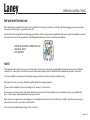
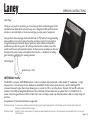
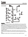
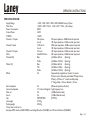
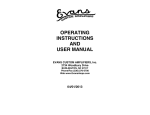
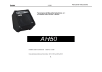
AH200
USER MANUAL
IMPORTANT SAFETY INSTRUCTIONS
WARNING: When using electric products, basic cautions should always be followed, including the following.
1. Read all safety and operating instructions before using this product
2. The product should be powered by a three pin `grounded (or earthed) plug connected to a power socket with a grounded earth outlet.
3. All safety and operating instructions should be retained for future reference
4. Obey all cautions in the Operating instructions and on the back of the unit
5. All operating instructions should be followed
6. This product should not be used near water, i.e. a bathtub, sink, swimming pool, wet basement, etc.
7. This product should be located so that its position does not interfere with its proper ventilation. It should not be placed flat against a wall or placed in a built up enclosure that
will impede the flow of cooling air.
8. This product should not be placed near a source of heat such as stove, radiator, or another heat producing amplifier.
9. Connect only to a power supply of the type marker on the unit adjacent to the power supply cord.
10. Never break off the ground pin on a power supply cord.
11. Power supply cords should always be handled carefully. Never walk or place equipment on power supply cords. Periodically check cords for cuts or signs of stress, especially at
the plug and the point where the chord exits the unit.
12. The power supply cord should be unplugged when the unit is to be unused for long periods of time.
13. If this product is to be mounted in an equipment rack, rear support should be provided.
14. The user should allow easy access to any mains plug, mains coupler and mains switch used in conjunction with this unit thus making it readily operable.
15. Metal parts can be cleaned with a damp cloth. The vinyl covering used on some units can be cleaned with a damp cloth or ammonia based household cleaner if necessary.
Disconnect the unit from the power supply before cleaning.
16. Care should be taken so that objects do not fall and liquids are not spilled into the unit through any ventilation holes or openings. On no account place drinks on the unit.
17. A qualified service technician should check the unit if:
! The power cord has been damaged
! Anything has fallen or spilled into the unit
! The unit does not appear to operate correctly
! The unit has been dropped or the enclosure damaged.
18. The user should not attempt to service the equipment. All service work is done by a qualified service technician.
19. Exposure to extremely high noise levels may cause a permanent hearing gloss. Individuals vary considerably in susceptibility to noise induced hearing loss, but nearly everyone
will lose some hearing if exposed to sufficiently intense noise for a sufficient time. The U.S. Government's Occupational Safety and Health Administration (OSHA) has specified
the following permissible noise level exposure.
Duration Per Day In Hours
Sound Level dBA, slow response
8
90
6
92
4
95
3
97
2
100
1½
102
1
105
½
110
¼ or less
115
According to OSHA, any exposure in excess of the above permissible limits could result in some hearing loss. Ear plugs or protectors in the ear canals or over the ears must be
worn when operating this amplification system in order to prevent a permanent hearing loss if exposure exceeds the limits set forth above. To ensure against potentially dangerous
exposure to high sound pressure levels it is recommended that all persons exposed to equipment capable of producing high sound pressure levels such as this amplification system
be protected by hearing protectors while this unit is in operation.
SAVE THESE INSTRUCTIONS
Page 2 /12
Page 3 /12
Laney
OPERATING INSTRUCTIONS
BEFORE SWITCHING ON
After unpacking your amplifier check that it is factory fitted with a three pin 'grounded' (or earthed) plug. Before plugging into the power supply
ensure you are connecting to a grounded earth outlet.
If you should wish to change the factory fitted plug yourself, ensure that the wiring convention applicable to the country where the amplifier is to be used
is strictly conformed to. As an example in the United Kingdom the cable colour code for connections are as follows.
EARTH OR GROUND - GREEN/YELLOW
NEUTRAL - BLUE
LIVE - BROWN
NOTE
This manual has been written for easy access of information. The front and rear panels are graphically illustrated, with each control and feature
numbered. For a description of the function of each control feature, simply check the number with the explanations adjacent to each panel.
Your Laney amplifier has undergone a thorough two stage, pre-delivery inspection, involving actual play testing.
When you first receive your Laney AudioHub amplifier, follow these simple procedures:
(i) Ensure that the amplifier is the correct voltage for the country it is to be used in.
ii) Connect your instrument with a high quality shielded instrument cable. You have probably spent considerable money on your amplifier and
guitar - don’t use poor quality cable it won’t do your gear justice.
Please retain your original carton and packaging so in the unlikely event that some time in the future your amplifier should require servicing you
will be able to return it to your dealer securely packed.
Care of your Laney amplifier will prolong it's life.....and yours!
Page 4 /12
Laney
OPERATING INSTRUCTIONS
Dear Player,
Thank you very much for purchasing your new Laney product and becoming part of the
worldwide Laney family. Each and every Laney unit is designed and built with the utmost
attention to care and detail, so I trust yours will give you many years of enjoyment.
Laney products have a heritage which stretches back to 1967 when I first began building
valve amplifiers in my parent’s garage. Since then we have moved on from strength to
strength developing an extensive range of guitar, bass, public address and keyboard
amplification products along with a list of Laney endorsees that includes some of the
world’s most famous and respected musicians. At the same time we believe we have not
lost sight of the reason Laney was founded in the first place - a dedication to building
great sounding amplification for working musicians.
Warm Regards,
Lyndon Laney CEO
INTRODUCTION
The AH200 is a compact 165W PA Workstation combo in a kickback style cabinet with a reflex loaded 15” loudspeaker + a high
frequency horn. Here at Laney we have dubbed it an AudioHUB. It features five separate channels, a built in 24bit digital FX
processor, footswitch option, Record out allowing you to connect to a PA or recording device. Channels 1+2 have Mic and Line in
sockets, a 2 band EQ and assignable effects level control. Channels 3-5 feature dual Line in sockets. There is a 3 band EQ in the
master section along with Aux and CD in sockets and a main out, finally a power amp distortion limiter is built in to keep things nice
and clean.
An explanation of these features follows on pages 6-8.
Definitions of Audio: A term used to describe sounds within the range of human hearing (20 Hz to 20 kHz) Also used to describe devices which are
designed to operate within this range.
Definition of hub: Hub is a place of convergence where data arrives from one or more directions and is forwarded out in one or more
Definition of Hub:
other directions.
Page 5 /12
Laney
1
2
5
3
OPERATING INSTRUCTIONS
4
8
6
7
9
10 11
12 13 15 18 16 20 17
14
19
21
22 23
FRONT PANEL CONTROLS
1 This gain control allows you to adjust the audio level of instruments connected to the Channel 1 Mic and Line In sockets.
2
The FX level control determines the amount of signal from this channel sent to the onboard DSP module and FX/Mon out
3
High/Treble frequencies can be boosted or cut by this control for this particular channel. Sources that fall in this range are
cymbals, soprano vocals and keys above top C on a keyboard.
4
Low/Bass frequencies can be boosted or cut by this control for this particular channel. Sources that fall in this range are bass
guitar, kick drums, deep vocals and keys below middle C on a keyboard.
5
The Mic input is designed for low impedance microphones (200-600ohms), it is a balanced XLR so will work equally well with
microphones that are balanced or unbalanced. Level controlled by
21
1
6
The Line In socket is designed for line level signals such as those obtained from keyboards, sound modules and sounds cards.
Level controlled by
(Both mic and line in sockets may be used at the same time.)
1
7
The High Impedance input is designed to accept many different types of instrument, and is particularly suited for instruments
such as acoustic guitars with piezo pickup systems.
Page 6 /12
Laney
8
OPERATING INSTRUCTIONS
The onboard digital effects have been custom designed by Laney to complement the AH200 with a choice of delays, flange,
Rotary, Octave Down, Chorus, Reverb and combinations of these. Select the chosen effect here and then control the overall
level with and each channels individual level with
9
9
2
Sets the overall master level for the onboard effects section.
10 Enables the onboard digital effects processor. To allow remote switching of the effects, this switch must be switched in.
11 This socket is for the connection of a Laney FS1 mono footswitch, to remotely switch the effects section on and off.
12 RCA Phono socket input for the connection of line level equipment like CD/MP3 Players etc. The level is controlled by
13 Adjusts the input level of equipment connected to the CD input sockets
13
12
14 RCA Phono socket output that is post EQ and pre master volume for the connection to an external recording device, PA
system etc.
15 This is the master Bass control and affects the main mixed signal (ie. all channels)
16 This is the master Middle control and affects the main mixed signal (ie. all channels)
17 This is the master Treble control and affects the main mixed signal (ie. all channels)
18 Controls the input level through the Aux in socket
19
19 The Aux in socket allows you connect an external device such as the output from an effects processor or sub mixer. The level
is controlled by
18
20 Controls the overall sound level from the amplifier and to the main out socket
22
21 The FX/mon out socket contains the main FX bus signal prior to being routed to the internal effects processor. You can use
this to route to an external FX processor/PA System/Monitors instead if you wish. The level is channel dependent.
22 The main out socket contains the final mixed signal post master volume and prior to routing to the internal amplifier. Use it
for driving external power amplifiers etc.
23 Indicates that power is on and the unit active. (Always switch off and disconnect power cord when not in use)
Page 7 /12
Laney
1
2
3
OPERATING INSTRUCTIONS
4
5
FRONT PANEL CONTROLS
1 Power inlet socket. Connect to your power source. Make sure the specified voltage is correct for your country!
2
This drawer contains the main safety fuse for the unit.
USE ONLY THE CORRECT SIZE AND RATING OF FUSE AS SPECIFIED ON THE PANEL.
The mains fuse ratings are detailed in the specs section at the rear of this manual.
3
The main power switch for the unit.
4
Serial Number and model of your unit.
5
This socket(s) should be used to connect an extension-cabinet. One socket is already used to connect to the internal
loudspeaker, you may use the free socket to connect to an external speaker cabinet if you wish. The impedance of the extension
cabinet must not be less than 8 Ohms. Connecting cabinets that have a lower impedance than 8 Ohms will result in the
amplifier overheating. Continual use in this manner may cause permanent damage. Connecting a cabinet with an impedance of
greater than 8 Ohms will cause no damage to the amplifier but will result in a reduced output level. You may disconnect the
internal loudspeaker, in this case the total impedance connected must not be less than 4 Ohms. eg two 8 Ohm cabinets.
Page 8 /12
Laney
OPERATING INSTRUCTIONS
OTHER FEATURES
Your AH200 features a kick style design to enable you to use it as a stage monitor, or a conventional straight combo.
SAMPLE SYSTEM
Page 9 /12
Laney
SPECIFICATIONS
CD in
EFFECTS
BLOCK DIAGRAM
Line In
Channel 1
Mic
MASTER
CD out
GAIN
EQ SECTION
Main Out
EQ SECTION
VOLUME
Line In
Channel 2
Mic
EXT. SPEAKER
GAIN
EQ SECTION
AUX LEVEL
POWER
AMP
AUX IN
INTERNAL
LOUDSPEAKER
Line In
Channel 3
HiZ
GAIN
FX/Mon Out
REMOTE
EQ SECTION
Line In
FX LEVEL
Channel 4
EFFECTS
SECTION
GAIN
Line In
EQ SECTION
Channel 5 as Channel 4
General Notes
Amplifier connection: In order to avoid damage, it is advisable to establish and follow a pattern for turning on and off your
equipment. With all system parts connected, turn on source equipment, tape decks, cd players, mixers, effects processors etc.
BEFORE turning on your AUDIOHUB. Many products have large transient surges at turn on and off which can cause damage to
your speakers. By turning on your AUDIOHUB LAST and making sure its Volume control is set to minimum any transients from
other equipment will not reach your loudspeakers. Wait until all system parts have stabilised; usually a couple of seconds. Similarly
when turning off your system always turn down the Volume control on your AUDIOHUB and then turn off its power before
turning off other equipment.
Caution: These professional loudspeaker systems are capable of generating very high sound pressure levels. Use care with
placement and operation to avoid exposure to excessive levels that can cause permanent hearing damage. (Refer to guidelines on
page 2)
Servicing: The user should not attempt to service these products. Refer all servicing to qualified service personnel.
Page 10 /12
Laney
OPERATING INSTRUCTIONS
SPECIFICATIONS
Supply Voltage
Mains Fuse
Power Consumption
Output Power
THD%N
Channel 1+2 Inputs
Channel 3 Inputs
Channel 4+5 Inputs
CD In
Channel EQ’s
Master EQ
Effects
~100V, ~120V, ~220V, ~230V, ~240V 50/60Hz Factory Option
~220V>~240V = T2A L. ~100>~120V = T5A L (Time delay)
300W
165W
<0.03%
Microphone
2K input impedance, -30dBu Nominal input level
Line In
10K Input impedance, -15dBu nominal input level
470k input impedance, -30dBu nominal input level
Hi Z Line In
10K Input impedance, -15dBu nominal input level
Line In
10K Input impedance, -15dBu nominal input level
2*Line In
Dual RCA Phono
22K input impedance, -10dBu Nominal input level
Bass
(±15dBu at 60 Hz)
(Shelving)
Treble
(±15dBu at 10 KHz) (Shelving)
Bass
(±15dBu at 60 Hz)
(Shelving)
Mid
(±15dBu at 2 KHz)
(Shelving)
Treble
(±15dBu at 10 KHz) (Shelving)
Yes
Independently assignable to channel 1-5, master
FX level control. Remotely switchable. 4*Delay, Octave,
2*Rotary, 2*Chorus, 2 * reverbs, multitap delay,
2 * flange, Delay + Chorus, Reverb + Chorus.
Yes
(Minimum impedance 8 ohms)
15” Custom Designed + high frequency horn
Yes
(+4dBu Nominal Level)
Yes
(-10dBu Nominal Level)
580*505*460
(H*W*D)
27.5 Kg
29.4 Kg
Ext Loudspeaker
Internal loudspeaker
Main out
Aux In
Size
Unit weight
Packing weight
This product conforms to:
European EMC directive (2004/108/EC), Low Voltage Directive (72/23/EEC) and CE mark Directive (93/68/EEC)
Page 11 /12
Laney
POWER TO THE MUSIC
METAL
BLUES
JAZZ
ROCK
AMPICONS ARE HERE TO HELP!
@
In the interest of continued product development, Laney reserves the right to amend product specification without prior notification.