1
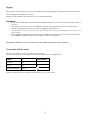
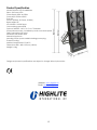
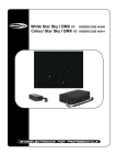
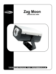
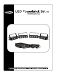
LED PowerBlinder 8
ORDERCODE 41321
Congratulations!
You have bought a great, innovative product from Showtec.
The Showtec LED PowerBlinder brings excitement to any venue. Whether you want simple plug-&-play action
or a sophisticated DMX show, this product provides the effect you need.
You can rely on Showtec, for more excellent lighting products.
We design and manufacture professional light equipment for the entertainment industry.
New products are being launched regularly. We work hard to keep you, our customer, satisfied.
For more information: [email protected]
You can get some of the best quality, best priced products on the market from Showtec.
So next time, turn to Showtec for more great lighting equipment.
Always get the best -- with Showtec !
Thank you!
Showtec
Showtec LED PowerBlinder™ Product Guide
Warning..…...................................................................................………………………………………….
Safety-instructions………………………………………………………………………………………….….
Operating Determinations…………………………………………………………………………………….
Rigging………………………………………………………………………………………………………….
2
2
3
4
Description..…..............................................................................……….…………………………………
5
Features and Overview ………………………………...….……………….………….………………….…. 5
Backside…………………………………………………...…...….……………….…………………...….….
6
Installation...............................................................................…...…………………………………….…..
6
Set Up and Operation.....................................................................……..…………………………….……
Stand-alone …….…………………………………………………….………………………….…….………
DMX Mode……………....…………..…………………………………………………………….……...……
Mode 1 - 16 Channels..…………………………………………………………….……...…………….
Mode 2 - 10 Channels..…………………………………………………………….……...…………….
Mode 3 - 7 Channels..…………………………………………………………….……...………………
Mode 4 Built-in Programs..…………………………………………………………….……...…………
Mode 5 Sound-active..…………………………………………………………….……...……………..
6
7
8
8
10
11
12
13
Maintenance...................................................................................………..………….…….……………… 14
Changing the Fuse........................................................................…………………….………….……… 14
Troubleshooting............................................................................………………….………………….…..
14
Product Specifications.................................................................……………….…….…………………..
15
1
WARNING
CAUTION!
Keep this device away from rain and moisture!
FOR YOUR OWN SAFETY, PLEASE READ THIS USER MANUAL CAREFULLY
BEFORE YOUR INITIAL START-UP!
SAFETY INSTRUCTIONS
Every person involved with the installation, operation and maintenance of this device has to:
be qualified
follow the instructions of this manual
CAUTION! Be careful with your operations.
With a dangerous voltage you can suffer
a dangerous electric shock when touching the wires!
Before your initial start-up, please make sure that there is no damage caused by transportation. Should there
be any, consult your dealer and do not use the device.
To maintain perfect condition and to ensure a safe operation, it is absolutely necessary for the user to follow
the safety instructions and warning notes written in this manual.
Please consider that damages caused by manual modifications to the device are not subject to warranty.
This device contains no user-serviceable parts. Refer servicing to qualified technicians only.
IMPORTANT:
The manufacturer will not accept liability for any resulting damages caused by the non-observance
of this manual or any unauthorized modification to the device.
•
•
•
•
•
•
•
•
•
•
•
•
•
•
•
•
Never let the power-cord come into contact with other cables! Handle the power-cord and all
connections with the mains with particular caution!
Never remove warning or informative labels from the unit.
Never leave any cables lying around.
Never look directly into the light source.
Never use the device during thunderstorms, unplug the device immediately.
Do not insert objects into air vents.
Do not open the device and do not modify the device.
Do not connect this device to a dimmerpack.
Do not shake the device. Avoid brute force when installing or operating the device.
Do not switch the device on and off in short intervals, as this would reduce the system’s life.
Only use device indoor, avoid contact with water or other liquids.
Only operate the fixture after having checked that the housing is firmly closed and all screws are
tightly fastened.
Only operate the device after having familiarized with its functions.
Avoid flames and do not put close to flammable liquids or gases.
Always keep case closed while operating.
Always allow free air space of at least 50 cm around the unit for ventilation.
2
•
•
•
•
•
•
•
•
•
•
•
•
•
•
•
•
Always disconnect power from the mains, when device is not used or before cleaning! Only handle
the power-cord by the plug. Never pull out the plug by tugging the power-cord.
Make sure that the device is not exposed to extreme heat, moisture or dust.
Make sure that the available voltage is not higher than stated on the rear panel.
Make sure that the power-cord is never crimped or damaged. Check the device and the powercord from time to time.
Make sure that no side forces can impact on the truss system.
The cable insert or the female part in the device must never be strained. There must always be
sufficient cable to the device. Otherwise, the cable may be damaged which may lead to deadly
electrical shocks.
If the external cable is damaged, it has to be replaced by a qualified technician.
If device is dropped or struck, disconnect mains power supply immediately. Have a qualified
engineer inspect for safety before operating.
If the device has been exposed to drastic temperature fluctuation (e.g. after transportation), do not
switch it on immediately. The arising condensation water might damage your device. Leave the
device switched off until it has reached room temperature.
If your Showtec device fails to work properly, discontinue use immediately. Pack the unit securely
(preferably in the original packing material), and return it to your Showtec dealer for service.
For adult use only. The device must be installed out of the reach of children. Never leave the unit
running unattended.
The user is responsible for correct positioning and operating of the LED PowerBlinder. The
manufacturer will not accept liability for damages caused by the misuse or incorrect installation of
this device.
This device falls under protection class I. Therefore it is essential to connect the yellow/green
conductor to earth.
For replacement use fuses of same type and rating only.
Repairs, servicing and electric connection must be carried out by a qualified technician.
WARRANTY: Till one year after date of purchase.
CAUTION ! EYEDAMAGES !.
Avoid looking directly into the light source.
(meant especially for epileptics) !
OPERATING DETERMINATIONS
This device is not designed for permanent operation. Consistent operation breaks will ensure that the device
will serve you for a long time without defects.
The minimum distance between light-output and the illuminated surface must be more than 0,5 meters.
The maximum ambient temperature ta = 45°C must never be exceeded.
The relative humidity must not exceed 50 % with an ambient temperature of 45° C.
If this device is operated in any other way, than the one described in this manual, the product may suffer
damages and the warranty becomes void.
Any other operation may lead to dangers like short-circuit, burns, electric shock, lamp explosion, crash etc.
You endanger your own safety and the safety of others!
3
Rigging
Please follow the European and national guidelines concerning rigging, trussing and all other safety issues.
Do not attempt the installation yourself !
Always let the installation be carried out by an authorized dealer !
Procedure:
•
•
•
•
•
If the LED PowerBlinder is lowered from the ceiling or high joists, professional trussing systems have to
be used.
Use a clamp to mount the LED PowerBlinder, with the mounting-bracket, to the trussing system.
The LED PowerBlinder must never be fixed swinging freely in the room.
The installation must always be secured with a safety attachment, e.g. an appropriate safety net or
safety-cable.
When rigging, derigging or servicing the LED PowerBlinder, always make sure, that the area below
the installation place is blocked and staying in the area is forbidden.
Improper installation can cause serious damage to people and property !
Connection with the mains
Connect the device to the mains with the power-plug.
Always pay attention, that the right color cable is connected to the right place.
Cable
Pin
International
BROWN
FASE
L
BLUE
NUL
N
YELLOW/GREEN
EARTH
Make sure that the device is always connected properly to the earth!
4
Description of the device
Features
The LED PowerBlinder is a LED system from Showtec.
• Ultra bright LED
• 96X 1W High Power LED's (32x Red, 32x green and 32x Blue)
• Reflected beam angle 25°
• LED Lifetime 100.000 hours
• Colour mixing system RGB
• Protocol DMX512, 16, 10 or 7 channels
• 3 Stand alone modes, controlled by audio or manual speed
• DMX Connection XLR 3-pins
• Aluminium with black finish
• Internal microphone
• Including 100cm power cable including power plug
• Transmit cooling
• Unlimited colors
• Low power consumption
• No Ultra Violet
• Adjustable hanging brackets included
• Maximum ambient temperature +50 degrees
NOTE: Knowledge of DMX is required to fully utilize this unit.
Overview
Fig. 1
5
Backside
Fig. 2
1) LCD Display
2) Functions: Mode, Menu, Up, Down
3) 3-pin DMX signal connector (OUT)
4) 3-pin DMX signal connector (IN)
5) Microphone
6) Audio Sensitivity
7) ) IEC Connector
8) Fuse 2A
9) Earth
10) ON / OFF
When the display shows
the Powerblinder is in auto Mode.
,
When the display shows
the Powerblinder is sound-active.
,
Note: The position of the point shows which mode is active.
Before the r (Auto); after r (Audio)
Installation
Remove all packing materials from the LED PowerBlinder. Check that all foam and plastic padding is
removed. Connect all cables.
Always disconnect from electric mains power supply before cleaning or servicing.
Damages caused by non-observance are not subject to warranty.
Set Up and Operation
Before plugging the unit in, always make sure that the power supply matches the product specification
voltage. Do not attempt to operate a 120V specification product on 230V power, or vice versa.
Note : Link all cables before connecting electric power.
6
FUNCTIONS:
There are 2 options for using the LED PowerBlinder:
Stand-alone
DMX Mode
Stand-alone
In Stand-alone mode, you can use the menu button on the back of the device to scroll through the options.
Strobe Programs
Open
Strobe 1-20 Hz
Strobe effect 1 (Rainbow + Slow Fade-in Strobe)
Strobe effect 2 (Rainbow + Mid-speed Fade-in Strobe)
Strobe effect 3 (Rainbow + Fast Fade-in Strobe)
Strobe effect 4 (Rainbow + Slow Fade-out Strobe)
Strobe effect 5 (Rainbow + Mid-speed Fade-out Strobe)
Strobe effect 6 (Rainbow + Fast Fade-out Strobe)
Strobe effect 7 (Slow random Strobe)
Strobe effect 8 (Mid-speed random Strobe)
Strobe effect 9 (Fast random Strobe)
No Strobe
7
DMX Mode
Spot Sections
The LED Powerblinder will automatically detect the presence of a DMX signal.
If a DMX signal is present, the DMX LED will blink.
In order to receive a DMX signal, the controller must be attached to a DMX controller by a 3-pin DMX cable
and the DMX controller must be turned on.
The LED PowerBlinder system can operate as a 16-, 10-, or 7-channel DMX fixture.
Channel 1 – Mode Options
0-15
16-49
50-99
100-149
150-199
200-255
Off
Mode 1 (16 DMX Channels)
Mode 2 (10 DMX Channels)
Mode 3 (7 DMX Channels)
Mode 4 (Built-in Programs Auto-run)
Mode 5 (Sound-active)
With the first channel, you can set how many channels you want to use, by choosing your desired mode.
Example: When you want to use 16 channels, you select Mode 1.
Note: For the Strobe to function, you have to set the dimmer to open and you select which Spot section you
want to strobe.
Mode 1 - 16 Channels (Channel 1 must be set to 16-49)
Channel 2 – No Function
Channel 3 – Strobe
0-15
16-141
142-150
151-160
161-170
171-180
181-190
191-200
201-210
211-220
221-230
231-255
Open
Strobe 1-20 Hz
Strobe effect 1 (Rainbow + Slow Fade-in Strobe)
Strobe effect 2 (Rainbow + Mid-speed Fade-in Strobe)
Strobe effect 3 (Rainbow + Fast Fade-in Strobe)
Strobe effect 4 (Rainbow + Slow Fade-out Strobe)
Strobe effect 5 (Rainbow + Mid-speed Fade-out Strobe)
Strobe effect 6 (Rainbow + Fast Fade-out Strobe)
Strobe effect 7 (Slow random Strobe)
Strobe effect 8 (Mid-speed random Strobe)
Strobe effect 9 (Fast random Strobe)
No Strobe
8
Channel 4 – Dimmer
0-255
Dimmer, from closed to open (0-100%)
Channel 5 – Red Dimmer Spot 1
0-255
Dimmer, from closed to open (0-100%)
Channel 6 – Green Dimmer Spot 1
0-255
Dimmer, from closed to open (0-100%)
Channel 7 – Blue Dimmer Spot 1
0-255
Dimmer, from closed to open (0-100%)
Channel 8 – Red Dimmer Spot 2
0-255
Dimmer, from closed to open (0-100%)
Channel 9 – Green Dimmer Spot 2
0-255
Dimmer, from closed to open (0-100%)
Channel 10 – Blue Dimmer Spot 2
0-255
Dimmer, from closed to open (0-100%)
Channel 11 – Red Dimmer Spot 3
0-255
Dimmer, from closed to open (0-100%)
Channel 12 – Red Dimmer Spot 3
0-255
Dimmer, from closed to open (0-100%)
Channel 13 – Red Dimmer Spot 3
0-255
Dimmer, from closed to open (0-100%)
Channel 14 – Red Dimmer Spot 4
0-255
Dimmer, from closed to open (0-100%)
Channel 15 – Green Dimmer Spot 4
0-255
Dimmer, from closed to open (0-100%)
Channel 16 – Blue Dimmer Spot 4
0-255
Dimmer, from closed to open (0-100%)
9
Mode 2 - 10 Channels (Channel 1 must be set to 50-99)
Channel 2 – No Function
Channel 3 – Strobe
0-15
16-141
142-150
151-160
161-170
171-180
181-190
191-200
201-210
211-220
221-230
231-255
Open
Strobe 1-20 Hz
Strobe effect 1 (Rainbow + Slow Fade-in Strobe)
Strobe effect 2 (Rainbow + Mid-speed Fade-in Strobe)
Strobe effect 3 (Rainbow + Fast Fade-in Strobe)
Strobe effect 4 (Rainbow + Slow Fade-out Strobe)
Strobe effect 5 (Rainbow + Mid-speed Fade-out Strobe)
Strobe effect 6 (Rainbow + Fast Fade-out Strobe)
Strobe effect 7 (Slow random Strobe)
Strobe effect 8 (Mid-speed random Strobe)
Strobe effect 9 (Fast random Strobe)
No Strobe
Channel 4 – Dimmer
0-255
Dimmer, from closed to open (0-100%)
Channel 5 – Red Dimmer Spot 1 + 2
0-255
Dimmer, from closed to open (0-100%)
Channel 6 – Green Dimmer Spot 1 + 2
0-255
Dimmer, from closed to open (0-100%)
Channel 7 – Blue Dimmer Spot 1 + 2
0-255
Dimmer, from closed to open (0-100%)
Channel 8 – Red Dimmer Spot 3 + 4
0-255
Dimmer, from closed to open (0-100%)
Channel 9 – Green Dimmer Spot 3 + 4
0-255
Dimmer, from closed to open (0-100%)
Channel 10 – Blue Dimmer Spot 3 + 4
0-255
Dimmer, from closed to open (0-100%)
10
Mode 3 - 7 Channels (Channel 1 must be set to 100-149)
Channel 2 – No Function
Channel 3 – Strobe
0-15
16-141
142-150
151-160
161-170
171-180
181-190
191-200
201-210
211-220
221-230
231-255
Open
Strobe 1-20 Hz
Strobe effect 1 (Rainbow + Slow Fade-in Strobe)
Strobe effect 2 (Rainbow + Mid-speed Fade-in Strobe)
Strobe effect 3 (Rainbow + Fast Fade-in Strobe)
Strobe effect 4 (Rainbow + Slow Fade-out Strobe)
Strobe effect 5 (Rainbow + Mid-speed Fade-out Strobe)
Strobe effect 6 (Rainbow + Fast Fade-out Strobe)
Strobe effect 7 (Slow random Strobe)
Strobe effect 8 (Mid-speed random Strobe)
Strobe effect 9 (Fast random Strobe)
No Strobe
Channel 4 – Dimmer
0-255
Dimmer, from closed to open (0-100%)
Channel 5 – Red Dimmer Spot 1 - 4
0-255
Dimmer, from closed to open (0-100%)
Channel 6 – Green Dimmer Spot 1 - 4
0-255
Dimmer, from closed to open (0-100%)
Channel 7 – Blue Dimmer Spot 1 - 4
0-255
Dimmer, from closed to open (0-100%)
11
Mode 4 Built-in Programs (Channel 1 must be set to 150-199)
Channel 2 – Colors
0-22
23-45
46-68
69-91
92-114
115-137
138-160
161-183
184-206
207-229
230-252
253-255
RGB rolling
RGBW flowing
WRGB flow recycle
WRGB chase
Each two spot-section has a WRGB chase
Red (all spots)
Green (all spots)
Blue (all spots)
Yellow (all spots)
Purple (all spots)
Cyan (all spots)
White (all spots)
Channel 3 – Strobe
0-15
16-141
142-150
151-160
161-170
171-180
181-190
191-200
201-210
211-220
221-230
231-255
Open
Strobe 1-20 Hz
Strobe effect 1 (Rainbow + Slow Fade-in Strobe)
Strobe effect 2 (Rainbow + Mid-speed Fade-in Strobe)
Strobe effect 3 (Rainbow + Fast Fade-in Strobe)
Strobe effect 4 (Rainbow + Slow Fade-out Strobe)
Strobe effect 5 (Rainbow + Mid-speed Fade-out Strobe)
Strobe effect 6 (Rainbow + Fast Fade-out Strobe)
Strobe effect 7 (Slow random Strobe)
Strobe effect 8 (Mid-speed random Strobe)
Strobe effect 9 (Fast random Strobe)
No Strobe
Channel 4 – Dimmer
0-255
Dimmer, from closed to open (0-100%)
Channel 5 – Fade time
0-255
Fade Time, from slow to fast (0-100%)
Channel 6 – Chase Time
0-255
Chase Time, from slow to fast (0-100%)
12
Mode 5 Sound-active (Channel 1 must be set to 200-255)
Channel 2 – Colors
0-22
23-45
46-68
69-91
92-114
115-137
138-160
161-183
184-206
207-229
230-252
253-255
RGB rolling
RGBW flowing
WRGB flow recycle
WRGB chase
Each two spot-section has a WRGB chase
Red (all spots)
Green (all spots)
Blue (all spots)
Yellow (all spots)
Purple (all spots)
Cyan (all spots)
White (all spots)
Channel 3 – Strobe
0-15
16-141
142-150
151-160
161-170
171-180
181-190
191-200
201-210
211-220
221-230
231-255
Open
Strobe 1-20 Hz
Strobe effect 1 (Rainbow + Slow Fade-in Strobe)
Strobe effect 2 (Rainbow + Mid-speed Fade-in Strobe)
Strobe effect 3 (Rainbow + Fast Fade-in Strobe)
Strobe effect 4 (Rainbow + Slow Fade-out Strobe)
Strobe effect 5 (Rainbow + Mid-speed Fade-out Strobe)
Strobe effect 6 (Rainbow + Fast Fade-out Strobe)
Strobe effect 7 (Slow random Strobe)
Strobe effect 8 (Mid-speed random Strobe)
Strobe effect 9 (Fast random Strobe)
No Strobe
Channel 4 – Dimmer
0-255
Dimmer, from closed to open (0-100%)
Channel 5 – Fade time
0-255
Fade Time, from slow to fast (0-100%)
Channel 6 – Chase Time
0-255
Chase Time, from slow to fast (0-100%)
13
Maintenance
The LED PowerBlinder requires almost no maintenance. However, you should keep the unit clean. Disconnect
the mains power supply, and then wipe the cover with a damp cloth. Do not immerse in liquid.
Keep connections clean. Disconnect electric power, and then wipe the connections with a damp cloth.
Make sure connections are thoroughly dry before linking equipment or supplying electric power.
Replacing a Fuse
Power surges, short-circuit or inappropriate electrical power supply may cause a fuse to burn out. If the fuse
burns out, the product will not function whatsoever. If this happens, follow the directions below to do so.
1. Unplug the unit from electric power source.
2. Insert a screwdriver into the slot in the fuse cover. Turn the screwdriver to the left, at the same time gently
push a bit (Turn and Push). The fuse will come out.
3. Remove the broken fuse. If brown or unclear, it is burned out.
4. Insert the replacement fuse into the holder where the old fuse was. Reinsert the fuse cover.
Be sure to use a fuse of the same type and specification. See the product specification label for details.
Troubleshooting
Showtec LED PowerBlinder
This troubleshooting guide is meant to help solve simple problems.
If a problem occurs, carry out the steps below in sequence until a solution is found. Once the unit operates
properly, do not carry out following steps.
If the light effect does not operate properly, refer servicing to a technician.
1. If the device does not operate properly, unplug the device.
2. Check the fuse, power from the wall, all cables etc.
3. If all of the above appears to be O.K., plug the unit in again.
4. If you are unable to determine the cause of the problem, do not open the LED PowerBlinder, as this may
damage the unit and the warranty will become void.
5. Return the device to your Showtec dealer.
14
Product Specification
Model: Showtec LED PowerBlinder
96pcs 1W Power LED's
Power Supply 230V Ac/50Hz
Power Input 0.33A at 230V
Fuse: 2A
96 LEDs (32 Red, 32 Green, 32 Blue)
Beam angle: 25°
LED Lifetime: 100.000 hours
Colour mixing system RGB
Protocol DMX512: 16CH, 10 CH or 7 Channels
3 Stand alone modes, controlled by audio or manual speed
DMX Connection XLR 3-pins
Aluminium with black finish
Internal microphone
Including 100cm power cable including power plug
Transmit cooling
Ambient temperature 0°C/40°C
Dimensions: 860 x 460 x 102 mm (LxWxH)
Weight 9.6 Kg
Design and product specifications are subject to change without prior notice.
Website: www.Highlite.nl
Email: [email protected]
15
2007 Showtec.