1
User Manual Content
Seite 1 von 108
Conrad Electronic GmbH, D-92240 Hirschau, http://www.conrad.de
Internet Connector Box
User Manual Rev 2.0
English Translation
Conrad-Best.-Nr. 120170
Important ! Read completely !
Before you use the Internet Connector Box or connect devices to the Internet Connector
Box, please read the Installation Manual completely ! It explains the correct use of the
Internet Connector Box and shows up possible hazard situations.
For damages, which result of disregarding this Installation Manual the company Conrad
Electronic can't make any guarantee or any responsibility.
Content
Important ! Read completely !
1.INTRODUCTION
1.1.Guarantee
1.2.Service
2.SHORT OVERVIEW OF THE USER MANUAL
2.1.Update possibilities
file://E:\html\gesamte.htm
10.09.99
User Manual Content
Seite 2 von 108
3.PRODUCT DESCRIPTION WITH THE POWER SUPPLY
3.1.Provision use
3.2.Security notice
3.3.Output figures
4.USING
4.1.Power on
5.INSTALLATION OF THE ICB
6.CONFIGURATION OVER A NULLMODEM CABLE
6.1.Generation of a Direct Connection from a PC to the ICB
6.2.Direct connection between your PC and the ICB
6.3.Connection to the ICB
7.INSTALLATION UNDER WINDOWS 9X
7.1.Installation of the Direct Connection
7.2.Copy the necessary Inf-File
7.3.Installation of the Nullmodem Cable
7.4.Installation of the Software-Components for a DFÜ-Connection
7.5.Installing the DFÜ-connection
7.6.Setting up the DFÜ-Network properties
7.7.Establishing a connection to the ICB
8.INSTALLATION UNDER WINDOWS NT 4.0
8.1.Configuration of the Null-Modem
8.2.Installation of the Software-components for a DFÜ-Network connection
8.3.Configuration of the DFÜ-connection
9.CONFIGURATION OF THE ICB
9.1.The User Interface
9.2.Configuration of Date and Time
9.3.Administration of the access rights
9.4.Create a new user account
9.5.Change existing user accounts
9.6.How to delete user accounts
9.7.Changing a password
10.LOOKING AT THE DEVICE PROPERTIES
10.1.Looking at the memory properties
10.2.Network properties
10.3.Services
10.4.Changing the properties of the services
10.5.Properties of the HTTP server service
10.6.Adding new HTTP rights
10.7.Changing HTTP rights
10.8.How to delete HTTP rights
10.9.Properties of the FTP server service
file://E:\html\gesamte.htm
10.09.99
User Manual Content
Seite 3 von 108
10.10.Properties of the NNTP server service
10.11.Properties of the Telnet service
10.12.CCG Server Properties
10.13.Configuration of the serial interfaces
10.14.Modems
10.15.Adding a new modem
10.16.Changing the modem parameters
10.17.How to delete a modem
10.18.Dial up connections
10.19.Add a new dial up connection
10.20.Changing a dial up connection
10.21.How to delete a dial up connection
10.22.Controller
10.23.How to display and change the C-Control Unit Properties
10.24.Delete C-Control units
10.25.Event display
11.TCP/IP SERVICE PROGRAMS
11.1.FTP
11.2.Telnet
11.3.Ping
12.CREATION OF EVENT-BASED ACTIONS
12.1.Release of an action
12.2.Definition of a new event
12.3.Event classes
12.4.Event class "Controller Variable"
12.5.Event class "File Event"
12.6.Event class "System Variable"
12.7.Event class "Combined Event"
12.8.Event class "Timer"
12.9.Event class "Internet"
12.10.Changing the properties of an existing event
12.11.How to delete an event
12.12.How to define actions
12.13.How to create a new action
12.14.Action classes
12.15.Action class "Log to File"
12.16.Action class "Set controller variable"
12.17.Action class "Send file via ftp"
12.18.Action class "System command"
12.19.Action class "Write to LCD"
12.20.Action class "Connect/Disconnect to Internet"
12.21.Action class "Send Template"
12.21.Changing of the properties of existing actions
12.21.How to delete an action
12.22.Combination of events and actions
12.23.Adding a new combination
12.24.Changing the properties of an existing combination
12.25.Deleting an existing combination
12.26.Apply the changes in a combination
13.CREATING OWN HTML PAGES
13.1.Gateways
13.2.CCG Server
file://E:\html\gesamte.htm
10.09.99
User Manual Content
Seite 4 von 108
13.3.Implementation
14.THE C-CONTROL PROTOCOL
14.1.Connection of the C-Control unit to the ICB
14.2.C-Control/BASIC programs
14.3.The communication via the C-Control protocol
14.4.Implementation of the C-Control protocol
14.5.Restrictions in the C-Control protocol
14.6.Program code examples
14.7.Running the C-Control unit at the ICB for the first time
15.TECHNICAL DATA
15.1.Hardware
15.2.Software
15.3.Delivery Specification
15.4.Recommended Power Supplies
15.5.Further Recommends
16.GLOSSARY
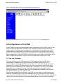
1.Introduction
We thank you for choosing the Internet Connector Box. The Internet Connector Box is
based on PC-Technology (chipPC-Technology)as an Internet Access-Box. The Internet
Connector Box was designed to meet the high expectation of our customers concerning
quality and functionality.
Conrad Electronic GmbH
D-92240 Hirschau
1.1.Garantie
Each Internet Connector Box has been tested and leaves our production fully
functionable !
Conrad Electronic gives a guarantee on each Internet Connector Box for 12 months. In
this time possible transport damages during the delivery process, production defects or
failure in the device will be repaired for free.
If the features of the Internet Connector Box should not meet your individual
requirements, use our 14 days money back guaranty. Send back the device in the
unmodified original packing during this time to get refunded or for setting of.
All deadlines are the date of invoice or the date of the sales slip.
Internal the Internet Connector Box are no parts for service needs through the user. The
Internet Connector Box must not be opened! In case of a broken white seal label all
guaranty expires!
Conrad Electronic does not take over any responsibility for consequential damage on
file://E:\html\gesamte.htm
10.09.99
User Manual Content
Seite 5 von 108
real value or person, which is caused by using the Internet Connector Box !
1.2.Service
For your consultation Conrad Electronic provides a competent team of service
employees. Each inquiry will be processed as soon as possible. Special questions will
be answered from our development engineers of the Internet Connector Box.
To avoid unnecessary delays, please consult the instruction manual, the online help of
the software, the text files and examples and also the possibilities of the information
sheets available via the internet before posting any inquiry. There you will find solutions
for most of your problems!
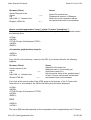
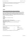
Please send your information request to the department of Technical customer Service:
Letter
Conrad Electronic GmbH
Abt.: Technische
Kundenbetreuung (TKB)
Klaus-Conrad-Straße 1
92240 Hirschau
Phone
0180 / 531 21 16
Fax
0180 / 531 21 19
Internet
http://www.conrad.de
http://www.c-control.de
2.Short Overview of the User Manual
The chapter Short Overview should declare the use of the ICB. Chapter 1 and chapter 3
to 8 contain the Installation Manual, which is supplemented as a paper manual in the
packing of the ICB. The complete User Manual is written as a HTML File on a CD. The
HTML file can be viewed with a Browser. The content of the User Manual contains 16
chapters.
1.) Introduction
2.) Short Overview of the User Manual
3.) Product-Descriptions with the Power Supply
4.) Using
5.) Installation of the ICB
6.) Configuration with Nullmodem Cable
7.) Installation under Windows 9x
8.) Installation under Windows NT 4.0
9.) Configuration of the ICB
10.) Looking at the Device Properties
11.) TCP/IP-Service Programs
12.) Creation of Event based Actions
file://E:\html\gesamte.htm
10.09.99
User Manual Content
Seite 6 von 108
13.) Creation own HTML pages
14.) The C-Control Protocol
15.) Technical Data
16.) Glossary
The Short Overview shows you the concept of the ICB and also the state of the delivery.
The ICB is a complete WebServer, which can be placed direct next to the application. In
the state of delivery the ICB is configured for the Conrad Electronic C-Control systems.
For the first installation the ICB can be connected over a Nullmodem Cable to a
standard PC or Laptop. Over the Browser the user can work with the ICB.
2.1.Update possibilities
Over the Hostmode software (works with a standard PC) and the Nullmodem cable
possible updates of program codes and alteration of the operating system of the ICB
can be done. The first delivery state of the ICB is software Rev. 1.08. The update of
HTML pages or DLL functions can be done over Internet updates via FTP.
The Hostmode software and also his User Manual can be accessed over the homepage
(http://www.mmc-ag.com and under the product name Internet Connector Box)
The C-Control Systems of Conrad Electronic are:
- C-Control/BASIC Unit und M-Unit
- C-Control/Station
The C-Control Systems are the first applications for the ICB. Further applications will
follow. They also can be accessed via homepage (http://www.mmc-ag.com and under
the product name Internet Connector Box).
A further application will be the connection of a CMOS-Camera over the Parallel port of
a printer.
A further application is the control over the Parallel port for single bit sets and single bit
inquiries.
The further application will continously increase and show the possibilities of the wide
area of the Embedded Internet Technology (EIT) (Measurements, Control, Observation).
3.Product Description with the Power Supply
3.1.Provision use
The Internet Connector Box (ICB) is configured as a MiniWebServer. Over a external
serial Modem (analog, ISDN or GSM) the ICB can connect to the Internet. A 9-12V DC
power supply (500mA) is necessary for the ICB.
file://E:\html\gesamte.htm
10.09.99
User Manual Content
Seite 7 von 108
Using the Internet Connector Box for other purposes is prohibited.
3.2.Security notice
Please read this chapter carefully !
1. The Internet Connector Box is supplied with power from a low voltage power
supply. Recommend plug in power supplies are:
1.1. Plug in power supply NG-500; 9-12V DC input; 500mA output current. Conradorder-No.: 518034
1.2. Mainy ;9V DC Input; output current 400mA; power 3,6W. Conrad-order-No.: 510998
Attention !!!!! With these power supplies power brakes of more than 1msec can't be
supported for the Internet Connector Box . For a power brake duration of until 10msec
please use external a 4700uF capacitor parallel to the DC-power supply.
The Internet Connector Box must not be used in connection with devices, which are
directly or indirectly used in medical ,health or live secure devices or which can cause
danger for persons, animals or real values. The Internet Connector Box must not be
used in explosive or chemical aggressive surroundings.
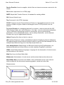
3.3.Output figures
The Internet Connector Box consists of the Internet Connector Box including installation
manual in paper form, Reference manual (HTML-File) and software utilities on CDROM.
l
l
l
Low voltage power supply connector to connect a DC plug In power supply
Serial interface COM 1
Serial interface COM 2
file://E:\html\gesamte.htm
10.09.99
User Manual Content
l
l
l
l
Seite 8 von 108
Serial interface COM 3
Serial interface COM 4
Parallel printer interface LPT 1
2x16 character display without backlight
A external modem (analog, ISDN or GSM) is necessary. The external modem must be
connected to one of the 4 serial interfaces of the Internet Connector Box.
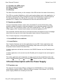
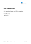
4.Using
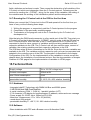
4.1.Power on
Please connect the low voltage connector to the connector of the Internet Connector
Box. Please pay attention to the correct polarisation.
The normal connection between the Internet Connector Box and the power supply is
demonstrated in the following picture:
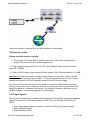
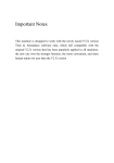
5.Installation of the ICB (ICB)
The ICB is installed with the base WebServer software. For the configuration and local
administration the ICB can be installed via a Nullmodem Cable. Therefore the
Nullmodem Cable connects the ICB with your PC or Laptop.
Note: The cable supplied with a C-Control/BASIC unit meets the requirements.
The basic installation of the ICB should be made in following the next four steps:
1. Plug In Power Supply
2. Nullmodem Cable between ICB (COM 2) and the PC
file://E:\html\gesamte.htm
10.09.99
User Manual Content
Seite 9 von 108
3. Modem connected to the ICB on (COM 1)
4. Application (e.g. weatherstation) connected to the ICB on (COM 4)
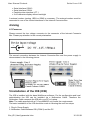
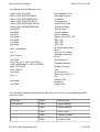
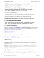
The Nullmodem Cable has following pinning:
Following pins of the DSUB connectors must be connected :
DSUB- 9 female DSUB-9 female
D1
1
2
3
4
5
6
7
8
9
with
with
with
with
with
is not connected
with
with
with
D2
4
3
2
1
5
6
8
7
9
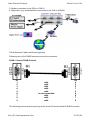
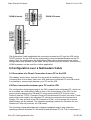
The following picture show the pinning at the 9 and 25 pinned female DSUB-Connector.
file://E:\html\gesamte.htm
10.09.99
User Manual Content
DSUB-9 female
Seite 10 von 108
DSUB-25 female
The Nullmodem Cable establishes the connection between the PC and the ICB via the
TCP/IP protocol. So the ICB can be configured by using a standard Browser on the PCstation. After the configuration the Nullmodem Cable can be disconnected and further
configurations and updates can be made via the internet using the modem. Now the free
COM2 connector can be used for a further application.
6.Configuration over a Nullmodem Cable
6.1.Generation of a Direct Connection from a PC to the ICB
This chapter should show, how the first use and first installation of the Internet
Connector Box is to be done, short form ICB, and how to install the PC and ICB so that
it is possible to communicate between your PC and the ICB.
6.2.Direct connection between your PC and the ICB
The configuration and programming of the ICB is realised with a standard PC, which can
be connected via a Nullmodem Cable to one of the 4 serial ports of the ICB. For the
communication between the ICB and PC usual protocols like PPP (Point-to-PointProtocol) and the TCP/IP (Transport Control Protocol/Internet Protocol) are used. These
protocols are also used by the standard PC, which is connected to the internet via a
modem. The user surface of the ICB is based on HTML, so the access with a normal
Web Browser can be realised. The standard operating systems like Windows 9x and
Windows NT offer all protocols, the ICB needs.
The following chapter describes the complete installation step by step under the
operating systems Windows 95, Windows 98 and Windows NT 4.0. This is necessary in
file://E:\html\gesamte.htm
10.09.99
User Manual Content
Seite 11 von 108
order to establish the direct communication with the ICB. Problems can be caused by
the fact, that some PCs are differently equipped.
For example there could already exist an internet or network connection on the PC.
Under these circumstances different solutions are possible. A step by step installation is
therefore limited. In this description we used only operating systems, which do not yet
have a connection to the internet or to other networks. So you have the complete
installation step by step you need for installing a ICB to access the internet.
6.3.Connection to the ICB
Before you start with the installation of the direct connection, the Nullmodem Cable must
be connected between one of the four serial ports of the ICB and one of the serial ports
of the PC. Activate the power supply connected to the ICB. The recommended power
supplies are described above. After power is turned on, the ICB starts the initialisation
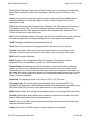
process. The initialisation routine is over when the 2 row display of the display shows
the ICB software version, the actual date and the actual hour.
ICB x.yz
dd.mm.ccyy hh:mm
7.Installation under Windows 9x
We start with the direct communication connection to the ICB under Windows 95 and
alternatively Windows 98.
The necessary installation steps under Windows 95 and Windows 98 are basically the
same.
There are different versions of the Windows 95 operating system. The first version on
the market is the version 4.00.950. Before beginning with the installation the dial-upnetworking Update 1.3 has to be installed, which can be found on the Microsoft
Homepage under http://www.microsoft.com. Please check the version of your Windows
95 system before continuing with the installation. The version of your system can be
found by opening the system control applet. If there the Built Number 4.00.950 and an
"a" or "b" is displayed no Dial-Up-Networking-Update is necessary.
7.1.Installation of the Direct Connection
To install the direct connection make the following steps.
7.2.Copy the necessary "mdmcisc2.inf" file
To install a connection via nullmodem under Windows9x you have to copy a special Inf
file, which is supplied on the CD to the directory c:\windows\inf , because the existing Inf
file of Windows9x doesn't allow a nullmodem installation for the nullmodem connection.
If we want to work with a Nullmodem Cable under Windows 95 or Windows 98 this
special Inf-File (mdmcisc2.inf) has to be copied in the directory c:\windows\inf.
7.3.Installation of the Nullmodem Cable
file://E:\html\gesamte.htm
10.09.99
User Manual Content
Seite 12 von 108
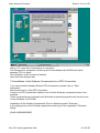
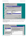
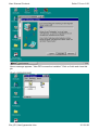
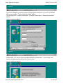
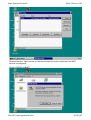
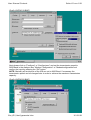
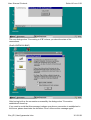
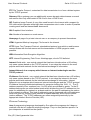
- Click on the desktop symbol START on in the task bar.
- Click on Modem
- Click on "Installing new modem".
{Grafik W95INS01.BMP}
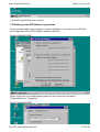
Click on Button "Select Modem" (no automatic control).
Click on "Further"
Then you see different types of modems listed.
{Grafik W95INS02.BMP}
file://E:\html\gesamte.htm
10.09.99
User Manual Content
Seite 13 von 108
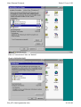
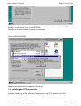
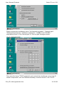
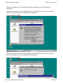
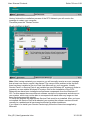
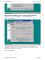
Click on "Select Modem" Select "Null Modem Types" the modell "RAS Serial Cable
between 2 PCs" .
{Grafik W95INS03.BMP}
In the next dialogue box select the COM-port, where the Nullmodem Cable is connected
to.
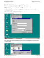
The dialogue box "Standortinformationen" is displayed.
{Grafik W95INS04.BMP}
file://E:\html\gesamte.htm
10.09.99
User Manual Content
Seite 14 von 108
Insert a "0" under Area Code and go to next point.
The dialogue box "properties" shows up and under Modems the RAS Serial Cabel
between 2 PCs is listed.
The installation of the modem is finished.
Now leave this dialogue box
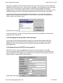
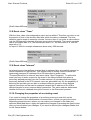
7.4.Installation of the Software-Components for a DFÜ-Connection
If you have installed already different DFÜ-connections, please click on "New
connection".
Now follow point 4. of the DFÜ-connection.
If there is no DFÜ-connection installed, first of all the Software components have to be
installed.
These components are included by all Windows 9x operating systems and can be found
on the Windows 9x CD-ROM.
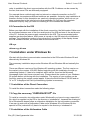
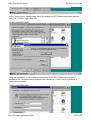
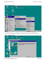
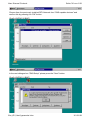
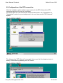
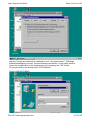
Installation of the Software Components Click on Desktop symbol "Software".
In the dialogue box of the Software properties window go to the registration "Windows
Setup"
{Grafik W95INS05.BMP}
file://E:\html\gesamte.htm
10.09.99
User Manual Content
Seite 15 von 108
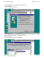
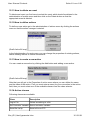
Click on "connections" then on "details".
{Grafik W95INS06.BMP}
file://E:\html\gesamte.htm
10.09.99
User Manual Content
Seite 16 von 108
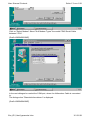
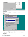
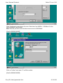
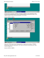
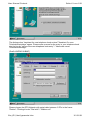
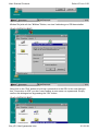
In the "connections" dialogue box check the marker for DFÜ-Network and then confirm
with "OK". Confirm again with "OK".
{Grafik W95INS07.BMP}
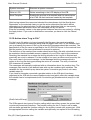
After the installation of the software components of the DFÜ-Network the selection
window of the Computer and workgroup name shows up, if there has not yet been a
group name installed.
{Grafik W95INS08.BMP}
file://E:\html\gesamte.htm
10.09.99
User Manual Content
Seite 17 von 108
Click on "OK" and enter a computer name and workgroup name.
Confirm with "OK"
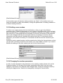
If you are working with Windows 95, the TCP/IP protocol is already installed. Windows
98 basically includes the TCP/IP protocol by default and therefore it is not necessary to
install it.
{Grafik W95INS09.BMP}
For the installation of TCP/IP under Windows 95 please go on window networking on
the registrationcard "Configuration". Click on "Add" and then you jump to "Network
component typ". Jump to "Protocol". Click on "Add", then you get to window "Network
protocol select" .
There you will find different protocols of different suppliers.
file://E:\html\gesamte.htm
10.09.99
User Manual Content
Seite 18 von 108
{Grafik W95INS10.BMP}
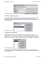
Choose "Microsoft" and then "TCP/IP" protocol, click on "OK", and the installation of the
TCP/IP protocol will be done.
Check this under Properties. Click in DFÜ-Driver under Properties, then you see that
TCP/IP is installed.
{Grafik W95INS11.BMP}
file://E:\html\gesamte.htm
10.09.99
User Manual Content
Seite 19 von 108
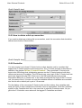
Activate on the registrationcard the TCP/IP button. Additionally deactivate IPX/SPX and
NetBEUI. Confirm with "OK". Click on "Close".
After that it is recommended to restart the computer.
{Grafik W95INS12.BMP}
After having restarted the installation is finished.
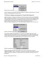
7.5. Installing the DFÜ-connection
After the installation of the Software-Components of the DFÜ-Network, the DFÜconnection to the ICB can be established.
file://E:\html\gesamte.htm
10.09.99
User Manual Content
Seite 20 von 108
{Grafik W95INS13.BMP}
Go to START; Programme; "Zubehör" ("Accessories") and click on "DFÜ-Network".
{Grafik W95INS14.BMP}
file://E:\html\gesamte.htm
10.09.99
User Manual Content
Seite 21 von 108
The Dialogbox Microsoft DFÜ-Network appears, click on "Further" and then appears
New connection.
{Grafik W95INS15.BMP}
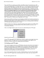
Enter a name for example ICB for the DFÜ-connection and choose under Modem the
RAS Serial Cable between 2 PCs.
{Grafik W95INS16.BMP}
file://E:\html\gesamte.htm
10.09.99
User Manual Content
Seite 22 von 108
Click Configuration and choose the max. Baud rate from 9600 to 115k Baud. All the
values between are possible.
Note: Basically all the serial interfaces are are set to 9600 Baud.
{Grafik W95INS18.BMP}
Click on "further" and enter "0" as Dial-number .
{Grafik W95INS19.BMP}
file://E:\html\gesamte.htm
10.09.99
User Manual Content
Seite 23 von 108
Now a message appears: "New DFÜ-connection installed." Click on finish and close this
job.
{Grafik W95INS20.BMP}
file://E:\html\gesamte.htm
10.09.99
User Manual Content
Seite 24 von 108
A new DFÜ-symbol has been created.
7.6.Setting up the DFÜ-Network properties
There must be made some changes in order to establish a connection to the ICB after
the configuration of the DFÜ-Network has been finished.
{Grafik W95INS21.BMP}
Simply right-click on the appropriate symbol for the connection and select
"Eigenschaften" or "Properties".
{Grafik W95INS22.BMP}
file://E:\html\gesamte.htm
10.09.99
User Manual Content
Seite 25 von 108
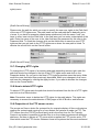
Please uncheck the checkboxes next to "Am Netzwerk anmelden" / "Network login",
"Softwarekomprimierung" / "Software compression", "NetBEUI" and "IPX/SPXcompatible protocol" in the "Servertypen" or "Server types" dialogue window.
{Grafik W95INS23.BMP}
Then select the frame "TCP/IP-properties" and uncheck the checkboxes next to "use IPHeader compression" and "use Standard-Gateway in remote network" in the TCP/IPfile://E:\html\gesamte.htm
10.09.99
User Manual Content
Seite 26 von 108
properties dialogue box.
Leave this dialogue window by pressing the "OK" button.
Confirm the changes made by pressing the "OK" button again.
7.7.Establishing a connection to the ICB
In order to establish a connection to the ICB simply double-click on the previously
created DFÜ-symbol.
A "Connecting with..." dialogue box opens.
{Grafik W95INS24.BMP}
Don't enter a user name or a password. Simply confirm the dialogue box by clicking the
"Connect" button.
{Grafik W95INS25.BMP}
file://E:\html\gesamte.htm
10.09.99
User Manual Content
Seite 27 von 108
The next dialogue box informs you about the state of the connection to the ICB.
User name: admin Password: admin
{Grafik W95INS26.BMP}
After the connection has succesfully built up the dialogue box "Connection established"
opens.
{Grafik W95INS28.BMP}
file://E:\html\gesamte.htm
10.09.99
User Manual Content
Seite 28 von 108
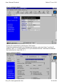
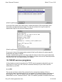
Shut this window and open your standard web browser (Netscape Communicator or
Microsoft Internet Explorer) and enter "http://" followed by the IP address "198.1.1.1" in
the address line of your web browser. The address line has to look like http://198.1.1.1
{Grafik W95INS29.BMP}
file://E:\html\gesamte.htm
10.09.99
User Manual Content
Seite 29 von 108
The configuration of the ICB or the installation of event-based actions has to be done in
the Administration menu. You get there by simply clicking the Aministration text link.
Enter admin as username and password in the dialogue box that shows up.
{Grafik WNTINS29.BMP}
After this you get to the administrative area of the ICB. Examples and information about
this is in this manual and on the CD under utilities.
file://E:\html\gesamte.htm
10.09.99
User Manual Content
Seite 30 von 108
8.Installation under Windows NT 4.0
If you have running Windows NT as your operating system you must use the so-called
"RAS-Dienst" or "RAS-Service" in order to establish a direct-connection to the ICB.
Setting up the direct connection under Windows NT has to be done like explained
below:
8.1.Configuration of the Null-Modem
Double-click on the "Arbeitsplatz" or "Workstation" symbol on your desktop and then in
the opened frame on the symbol for "Systemsteuerung" or "System properties" .
In the new frame "Systemsteuerung" or "System properties" click the "Modems" symbol.
After that a new dialogue box "Install a new modem" opens.
{Grafik WNTINS01.BMP}
Select the checkbox next to "Select modem (no automatic detection)" or "Modem
auswählen (keine automatische Erkennung)" and then click the "Next" button.
After that a list of all available modem drivers and devices sorted by their manufacturers
opens.
{Grafik WNTINS02.BMP}
file://E:\html\gesamte.htm
10.09.99
User Manual Content
Seite 31 von 108
Select "DFÜ-Network with a serial cable between 2 PCs" from the manufacturer
"Standard modem types" and confirm your choice by clicking the "Next" button.
{Grafik WNTINS03.BMP}
file://E:\html\gesamte.htm
10.09.99
User Manual Content
Seite 32 von 108
In the next dialogue box please select the appropriate COM port of your PC, where the
ICB is connected to. Then click on the "Next" button.
The dialogue box "Location information" ("Position information") "Standortinformation"
opens .
{Grafik WNTINS04.BMP}
Please enter a "0" next to "Kennzahl des aktuellen Ortsbereichs" / "Area Code" and
confirm this selection by clicking the "Next" button.
{Grafik WNTINS05.BMP}
file://E:\html\gesamte.htm
10.09.99
User Manual Content
Seite 33 von 108
You will receive a message that the modem has been configured. Click on "Finish".
{Grafik WNTINS06.BMP}
The dialogue box "Properties for modems" "Eigenschaften für Modems" opens, where
the "DFÜ-Network with a serial cable between 2 PCs is listed. The installation of the
modem is finished. Leave this dialogue box by clicking the "Close" button.
8.2.Installation of the Software-components for a DFÜ-Network
connection
file://E:\html\gesamte.htm
10.09.99
User Manual Content
Seite 34 von 108
After the installation of the Null-Modems a DFÜ-connection to the ICB must be
configured.
Therefore double-click on the "Workstation" or "Arbeitsplatz" symbol on your desktop
and in the opened frame on the symbol "DFÜ-Network".
{Grafik WNTINS07.BMP}
Therefore double-click on the "Workstation" or "Arbeitsplatz" symbol on your desktop
and in the opened frame on the symbol "DFÜ-Network"
{Grafik WNTINS08.BMP}
file://E:\html\gesamte.htm
10.09.99
User Manual Content
Seite 35 von 108
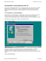
After the dialogue box DFÜ-Network has popped up begin the installation by clicking the
"Install" button.
Then you will receive the message that the DFÜ-Network is being installed and that
therefore some files are needed.
Insert your Windows NT CD in the CD-ROM drive and (enter the drive letter of your CDROM drive in the text field next to "Copy files from..." ) select your CD-ROM drive from
the list of all available drives with the pull-down menu.
Confirm your input by pressing the "OK" button.
After the copying process a new dialogue box "Add RAS-device" or "RAS-Gerät
hinzufügen" opens.
{Grafik WNTINS09.BMP}
file://E:\html\gesamte.htm
10.09.99
User Manual Content
Seite 36 von 108
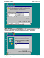
Choose from the previously installed DFÜ-Network from "RAS-capable devices" and
confirm this by pressing the "OK" button.
{Grafik WNTINS10.BMP}
In the next dialogue box "RAS-Setup" please press the "Next" button.
{Grafik WNTINS11.BMP}
file://E:\html\gesamte.htm
10.09.99
User Manual Content
Seite 37 von 108
If there has not yet been a network component installed on your computer you will
receive the warning that there must be installes at least one protocol for RAS. If this
happens please confirm this by pressing the "OK" button.
{Grafik WNTINS12.BMP}
Select the TCP/IP protocol as client-protocol by checking the checkbox "TCP/IP".
Confirm this choice by pressing the "OK" button so that you will get back the "RASSetup" dialogue box.
{Grafik WNTINS13.BMP}
file://E:\html\gesamte.htm
10.09.99
User Manual Content
Seite 38 von 108
Please press the "Next" button so that the necessary files are copied and the RASservice is configured.
{Grafik WNTINS14.BMP}
file://E:\html\gesamte.htm
10.09.99
User Manual Content
Seite 39 von 108
Having finished the installation process of the DFÜ-Network you will receive the
message to restart your computer.
Therefore press the "Restart" button.
{Grafik WNTINS15.BMP}
Note: After having restarted your computer you will normally receive an error message
that at least one service couldn´t be started. The cause of this problem is the fact that
there has been installed a Service Pack from Microsoft on your computer. Usually
Service Pack 3 or Service Pack 4 are installed on most Windows NT systems in order to
guarantee a more stable Windows NT system. But for the installation of the DFÜNetwork there have been installed some software components from the Windows NT
CD. For this reason there are different software versions of components and drivers on
your system, which may not be able to correspond with each other any longer so that
some services cannot be started.
To solve this problem the appropriate Service Pack must be re-installed. After you have
re-installed the Service Pack and rebooted your system the software versions should
normally be updated and all services should start up without problems.
If you have to re-install your Service Pack simply follow the instructions supplied by
Microsoft.
file://E:\html\gesamte.htm
10.09.99
User Manual Content
Seite 40 von 108
8.3.Configuration of the DFÜ-connection
After the installation of the software compoments for the DFÜ-Network the DFÜconnection with the ICB must be configured.
Therefore follow the next instructions: Please double-click on the "Workstation" or
"Arbeitsplatz" symbol on your desktop and in the next frame on the "DFÜ-Network"
symbol.
{Grafik WNTINS16.BMP}
The dialogue box "DFÜ-Network" opens and informs you that the telephone book is
emoty. Confirm this by ypressing the "OK" button.
{Grafik WNTINS17.BMP}
file://E:\html\gesamte.htm
10.09.99
User Manual Content
Seite 41 von 108
The dialogue box "assistant for new telephone book entries"/"Assistent für neue
Telefonbucheinträge" opens. Please enter a name for the entry in your telephone book
into the line by "name of the new telephone book entry" / "Name des neuen
Telefonbucheintrags".
{Grafik WNTINS18.BMP}
Please choose the DFÜ-Network with serial cable between 2 PCs in the frame
"Entries" /"Einträge"under "Dial with" /."Wählen mit"
file://E:\html\gesamte.htm
10.09.99
User Manual Content
Seite 42 von 108
{Grafik WNTINS19.BMP}
Next please click on "Configure" or "Konfigurieren" and set the transmission speed to
9600 Baud in the dialogue box "Modem Configuration" or "Modemkonfiguration"and
confirm the input by pressing the "OK" button.
NOTE: Basically all serial ports of the ICB are set to 9600 Baud. If necessary the
transmission speed can be changed later in order to achieve the maximum transmission
capacity.
{Grafik WNTINS20.BMP}
file://E:\html\gesamte.htm
10.09.99
User Manual Content
Seite 43 von 108
Please deactivate the checkboxes "Server", "Software compression" and "LCPextension for PPP". Activate the checkbox "TCP/IP" and press the button "TCP/IP
properties". So you get into the dialogue box "PPP TCP/IP properties".
{Grafik WNTINS21.BMP}
Uncheck the checkboxes "use IP-Prefix and compression" / "IP-Vorspann und
Komprimierung verwenden" and "use Standard-Gateway in remote network". Confirm
this selection by pressing the "OK" button.
{Grafik WNTINS22.BMP}
file://E:\html\gesamte.htm
10.09.99
User Manual Content
Seite 44 von 108
Activate "accept any authenticity certification (incl. Uncrypted ones)" / "Beliebige
Echtheitsbestätigung (einschl. unverschlüsselte) annehmen" in the safety window.
Leave the configuration of the telephone book by pressing the "OK" button.
So you get back to the dialogue box "DFÜ-Network".
{Grafik WNTINS23.BMP}
file://E:\html\gesamte.htm
10.09.99
User Manual Content
Seite 45 von 108
Klicken Sie jetzt auf den "Wählen" Button, um eine Verbindung zur ICB herzustellen.
{Grafik WNTINS24.BMP}
Now click on the "Dial" button to build up a connection to the ICB. In the next dialogue
box "Connection to ICB" you don´t need neither a user name nor a password. Simply
confirm this dialogue box by pressing the "OK" button.
{Grafik WNTINS25.BMP}
file://E:\html\gesamte.htm
10.09.99
User Manual Content
Seite 46 von 108
The next dialogue box "Connecting to ICB" informs you about the state of the
connections.
{Grafik WNTINS26.BMP}
After having built up the connection successfully the dialogue box "Connection
established" shows up.
If you want to avoid that this message is shown everytime a connection is established in
the future, please deactivate the checkbox "Don´t show me this message again."
file://E:\html\gesamte.htm
10.09.99
User Manual Content
Seite 47 von 108
{Grafik WNTINS27.BMP}
Confirm the connection by pressing the "OK" button.
Close this window and open your standard web browser and enter "http://" and the IP
address "198.1.1.1" in the address line of your standard browser. After that the address
line looks like this: http://198.1.1.1
{Grafik WNTINS28.BMP}
file://E:\html\gesamte.htm
10.09.99
User Manual Content
Seite 48 von 108
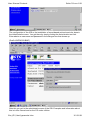
The configuration of the ICB or the generation of event depended actions has to be
done in the Administration menu. Please click on the Administration symbol. Enter the
user name admin and also the password admin.
{Grafik WNTINS29.BMP}
Now you get to the administration area.
To get the status of the DFÜ-connection, click on the DFÜ-symbol aside the watch in the
task toolbar and the DFÜ-monitor is shown. Here you can also disconnect the
established connection.
file://E:\html\gesamte.htm
10.09.99
User Manual Content
Seite 49 von 108
Here is the the menu shown in the Netscape Communicator
9.Configuration of the ICB
In this chapter we want to describe the system configuration of the ICB so that you can
make the basic configuration of the ICB. This consists of setting up date and time,
administration of access rights, configuration of the serial ports, configuration of the
modem and the configuration of the dial up connection for connecting to the Internet
Service Provider. After this chapter you should be able to make all the system specific
basic configurations of the ICB. We will describe every menu which is necessary for the
basic configuration so that you get to know all configuration options of the ICB.
9.1.The User Interface
The User Interface of the ICB is based on HTML pages so that the ICB can be
administered, operated and configured with any available web browser. The
administration is absolutely the same via the internet or via a direct serial connection
between a PC and the ICB. Exclusively for the first configuration of the ICB a direct
serial connection between the PC and the ICB is necessary. You can find a detailed
description in your manual or in this online documentation in the chapter Direct
connection between PC and ICB about how to configure and establish a direct serial
connection between your PC and the ICB.
After having established a connection to the ICB you can start your web browser and
enter the IP address of the ICB in the address line of your web browser. After that the
User Interface of the ICB builds up in your web browser. The time necessary for building
up the user interface depends on the transmission speed of the connection between
file://E:\html\gesamte.htm
10.09.99
User Manual Content
Seite 50 von 108
your PC and the ICB.
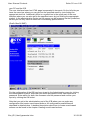
The user interface based on HTML page is separated in two parts. On the left side you
have the menu bar where you can get into the specified menu by just clicking the
appropriate text link. Additionally there is a symbol bar in the upper part of the user
interface where you can also get to the specified menu by just clicking the appropriate
symbol. In the administrative section not all menus can be accessed via the symbol bar,
so that you can only use the menu bar for accessing special menus.
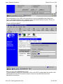
{Grafik Ober01.BMP}
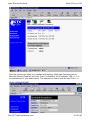
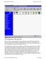
For the configuration of the ICB you have to get to the Administration menu by clicking
the Administration symbol. After that you will be prompted to enter username and a
password. Enter admin for both, the username and the password and confirm your
inputs by clicking the OK button.
After that you get to the administrative part of the ICB where you can make any
configuration and create event-based actions. All configuration possibilities are
described in details below. A detailed description about how to create event-based
actions can be found in the chapter Creating event-based actions.
file://E:\html\gesamte.htm
10.09.99
User Manual Content
Seite 51 von 108
{Grafik Ober02.BMP}
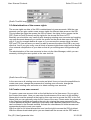
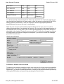
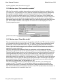
9.2.Configuration of Date and Time
Date and Time must be entered after the first operation of the ICB and basically after
each cold restart of the ICB again. The date and time information is important for the
creation of Log files and for the time-based control of actions of the ICB. Additionally the
time is displayed in the front LCD display of the ICB.
The configuration of date and time is made in the Date/Time menu which can accessed
by clicking the date symbol or the Date/Time text link. In the Date/Time menu you can
enter the day of the month in the date text fields, select the actual month and enter the
year. In the time text fields you can set the actual time in the format hh:mm:ss. In the
GMT (Global Main Time) field the time zone can be specified which is +1 in Germany.
Apply these changes by clicking the Apply button. By clicking the Cancel button
cancelled . After you have configured the time, the new changed time appears on the
LCD display of the ICB and all future events and actions base on this date and time from
the moment when you accepted the changes.
file://E:\html\gesamte.htm
10.09.99
User Manual Content
Seite 52 von 108
{Grafik Time001.bmp}
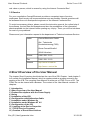
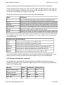
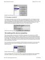
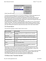
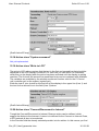
9.3.Administration of the access rights
The access rights on data of the ICB is administered via user accounts. With the user
accounts you can give certain users access rights for different data areas on the ICB.
This includes the rights the access the ICB via telnet, the rights for the access via the
PPP (Point-to-Point-Protocol) and the rights for the access on files via FTP.
Basically you should be very carefully with changing existing user accounts and creating
new user accounts because you control the access on the whole data area of the ICB
with it. If you for example delete all users or if you remove the access rights via telnet,
PPP and FTP from all users you won't be able to access the data of the ICB in any way
after this. And if you give every user all kinds of access rights there might be the danger
of an external manipulation of your data so that all your settings and configurations get
lost.
The administration of the user accounts is done via the User Manager, which you can
access by clicking the user symbol or the user text link.
{Grafik Accou01.bmp}
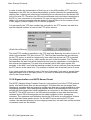
In the user menu all existing user accounts are listed. Here you have the possibilities to
create new users, change the passwords of existing user accounts, change the
properties of existing user accounts or to delete existing user accounts.
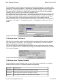
9.4.Create a new user account
To create a new user account click on the Add button in the User menu. So you get to
the Create User menu. Here you can enter the shortname of the user into the textfield
Name which must be entered at the login by this new user to access the ICB. In the Full
Name field you can optionally enter the full name of the user. Please enter the password
in the Password textfield and confirm the entry by retyping the same password in the
Confirm password textfield. Additional information and a detailed description of the user
can be entered in the Remark textfield. Activate the checkboxes full telnet access and
access deactivated to meet your needs.
With the right for full telnet access this user has the right to access the ICB via telnet.
With the access deactivated option you can deactivate the access via the PPP and so
file://E:\html\gesamte.htm
10.09.99
User Manual Content
Seite 53 von 108
restrict the access for the direct connection from the PC to one of the serial ports.
In the lower part of the Create user menu the FTP rights are administered. Here you can
on the one hand specify the path for the access on the available memory on the ICB and
on the other hand define each single access right.
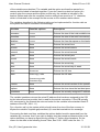
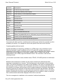
The directory structure on the ICB is build up like described below:
Pfad
Erklärung.
\
Root of the hard disk space and access to all subdirectories
\CFG
Directory for the configuration files where all system configurations are save
\NEWS
Directory where the news files for the transmission to the news server are cr
\SCHEDULE
Directory of the configuration files in which all alarms, actions and rules are
\WWW
Directory in which all the HTML files are saved
\PUB
Directory for which you need no password to access it; public area
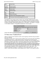
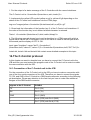
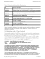
The available access rights refer to the standard FTP access rights which are described
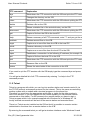
in the table below:
Zugriffsrecht
Beschreibung.
GET
Allows you to read data on the ICB via FTP
PUT
Allows you to write data on the ICB via FTP
DELETE
Allows you to delete files and directories on the ICB via FTP
MKDIR
Allows you to create new directories on the ICB via FTP
RMDIR
Allows you to remove directories from the ICB via FTP
If you want to save a newly created user account please click on the Apply button. If you
want to cancel the newly created user account please click on the Cancel button.
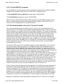
9.5.Change existing user accounts
Per default three users with the usernames admin, webmaster and anonymous are
created and available on the ICB whose rights and the FTP access path are defined like
listed in the following table.
Rechte
admin
webmaster
Anonymous
Voller Telnet Zugriff
Yes
No
No
Zugang sperren
No
No
No
FTP Verzeichnis
\
\www
\pub
FTP GET
Yes
Yes
Yes
file://E:\html\gesamte.htm
10.09.99
User Manual Content
Seite 54 von 108
FTP PUT
Yes
Yes
No
FTP DELETE
Yes
Yes
No
FTP MKDIR
Yes
Yes
No
FTP RMDIR
Yes
Yes
No
Default Paßwort
admin
webmaster
No
password !
You should specify new passwords for these user accounts out of security aspects, but
you should never delete one of these users so that the access on the data of the ICB is
always granted. Remember to note the username and the appropriate password
somewhere and to secure the note in a safe place.
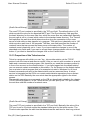
Mark the user account and click the properties button in the user menu in order to
change the properties of an existing user account. So you get to the properties menu of
the selected user account where you can change the properties in the fields which are
described in the chapter "Create a new user account". Confirm the changes by clicking
the Apply button so that the changes are accepted. If you want to cancel the changes
press the Cancel button.
{Grafik Accou02.bmp}
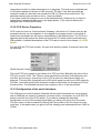
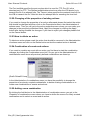
9.6.How to delete user accounts
To delete a user account mark the correct user account in the User menu and press the
Delete button. You will get a dialogue box if you really want to delete the selected user
account or if you want to cancel the deletion. Confirm to resume the deletion process by
clicking the OK button and cancel it by pressing the Cancel button.
file://E:\html\gesamte.htm
10.09.99
User Manual Content
Seite 55 von 108
{Grafik Accou03.bmp}
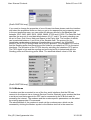
9.7.Changing a password
To change a password mark the chosen user account and click on the Password button
in the user menu. So you get to the user-specific Set password menu in which you can
enter a new password in the Password field and retype the new password in the Confirm
password field. By clicking the Apply button you can accept the new password. If you
want to dismiss the changed password just click on the Cancel button.
{Grafik Accou04.bmp}
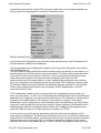
10.Looking at the device properties
The communication connections to the ICB are realised on the lowest level via PPP
(Point-to-Point Protocol). Therefore it doesn't matter if it is a local connection between a
PC and the ICB via a serial cable or a remote connection to an Internet Service Provider
via a modem. The ICB allows one PPP connection for each serial interface, so that there
can be maximal 4 connections at the same time which are each administered by the ICB
as an independent connection.
If you now want to look at the properties of one of these connections you must go to the
Connection menu which can be accessed by clicking the Connection symbol or the
Devices text link.
{Grafik Geraet01.bmp}
In the connection menu all now active PPP connection are listed which are enumerated
with PPP1 to PPP4. If you want to look at the status or the properties of the PPP
file://E:\html\gesamte.htm
10.09.99
User Manual Content
Seite 56 von 108
connection just mark the correct PPP connection and click on the Properties button so
that you get to the appropriate Connection Properties menu.
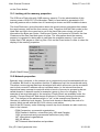
{Grafik Geraet02.bmp}
In the Connection Properties menu all used serial interfaces, the used IP address and
the transmission statistics are displayed.
Following properties are displayed in details in the Connection Properties menu which
are described below.
The HW-Address field specifies the serial interface which the device is connected to. In
the description text field the device type is described. The Status field shows the status
of the device which can be active or inactive. In the Connected with field the actually
used transmission speed in bits per second is displayed with which the ICB
communicates with the distant station. In the Connected since field the time is shown
since the connection to the distant system got activated. The IP address, Gateway and
IP netmask fields show the IP address, the standard gateway and the IP subnet mask.
These three address specifications are necessary for the addressation on the IP
(Internet Protocol) level.
The IP addresses consist of four numbers which are separated by points which can
have any value from 1 to 255. The so-called subnet mask belongs to the IP address and
separates the IP address in the area for the adressation of the network or subnet and in
the area for the addressation of the station in the network or subnet. This type of
addressation can be compared to mail addresses which are defined by the street name
(network or subnet address) and a house number (station address). Additionally the socalled gateway address is displayed which shows the IP address of the gateway over
which the data can be sent to other networks or subnet via TCP/IP.
In the counter area of the device properties menu the transmission statistics of the
connection are displayed. The Bytes sent field gives the amount of bytes that have been
transmitted to the distant station. Under Bytes received you can see the amount of bytes
that have been received by the ICB. If you want to update the display of the counter
statistics just click on the Update button. To leave the device properties menu just click
file://E:\html\gesamte.htm
10.09.99
User Manual Content
Seite 57 von 108
on the Close button.
10.1.Looking at the memory properties
The ICB has a Flash disk with 2 MB memory capacity. For the administration of this
memory area a 12 Bit FAT (File Allocation Table) is used which is separated in 512
bytes big sectors with a cluster size of 8 sectors per cluster and 430 available clusters.
The Hard Disk menu gives information about the actual memory properties that means
the used memory size and the free memory size. Therefore click the Disk symbol or the
Hard Disk text link in the menu bar to get to the Hard Disk menu where you get all
information like Bytes per Sector, Sectors per Cluster, the Amount of Clusters, the free
Clusters and the free hard disk space in bytes. The information about the memory
property is important for being able to calculate the available memory if you want to
create own HTML pages or new Log files. Click on the Close button in order to close the
display of the memory properties.
{Grafik Disk001.bmp}
10.2.Network properties
Basically every computer in the internet can or respectively must be addressed with an
IP address. But there is the problem that this IP addresses can't be remembered easily.
Therefore a name concept has been developed with which all servers can be accessed
next to their normal IP address with an individual name. In the internet therefore a
hierarchical name concept is used with which a bunch of servers is grouped under socalled domains. A domain equals for example a group in form of a company. For
example all servers belonging to the company Compu-Shack are available under the
domain ".Compu-Shack.de" and almost all servers in Germany belong to the domain
".de". This last part of the address which is ".de" in this example and stands for
Germany is called top level domain. The top level domain is basically the code of a
country which equals with the ISO 3166 country code tables.
Next to the ISO country codes following common top level domains are also used very
often in the internet:
.COM Companies, commercial organisations
.EDU Research facilities, universities (only USA and Canada)
.GOV governments and governmental institutions (only USA)
.INT International organisations
.MIL US-Military
.NET Network administration and providers
file://E:\html\gesamte.htm
10.09.99
User Manual Content
Seite 58 von 108
.ORG Other non-commercial organisations.
Each computer in a domain has his own host name with which he is addressed in the
domain.
For the administration of the domain and the conversion of the domain names to IP
addresses the so-called Domain Name Service (DNS) is responsible. Normally every
domain has its own DNS. All servers login at the DNS with their host names and IP
addresses. Now if someone wants to access this server he can use the host name and
the domain name in order to access this server, like for example "webmachine.compushack.de". The DNS is the top level domain ".de" and first of all converts the name of
the domain ".compu-shack" into an IP address. The DNS of the domain ".compushack.de" converts itself the hostname into an IP address.
If you want to configure the ICB for the implementation in a domain you can do this in
the Network menu which can be accessed by clicking the Network symbol or the
Network text link in the menu bar.
{Grafik Network1.bmp}
In the Network properties menu you can specify the hostname for the ICB, a domain
name and the IP address of a Primary and a Secondary DNS server.
Basically the information about the hostname and the domain name is only necessary if
the ICB is integrated in an Intranet. If the connection to the internet of the ICB is realised
with an Internet Service Provider it might be possible that you must specify the IP
addresses of the DNS servers if these aren't announced automatically by the dial up
process of your internet provider. For detailed information about this problem contact
your Internet Service Provider.
If necessary enter a hostname for your ICB into the text field Hostname that can be
maximal 255 characters long. In the Domain field you can enter the name of your
domain which must be entered in the form "domain name.de". In the Primary DNS field
you can enter the IP address of the DNS server and additionally for redundancy
purposes the IP address of a Secondary DNS server in the Secondary DNS field. The
secondary DNS is used for converting the domain names to IP addresses if the primary
DNS is temporarily not available.
Save this entries by clicking the Apply button or cancel your inputs by clicking the
Cancel button.
10.3.Services
The different functions of the ICB, like for example the HTTP server or the FTP server
file://E:\html\gesamte.htm
10.09.99
User Manual Content
Seite 59 von 108
are made available by the ICB with so-called services. Each service can by configured
adapted in the Services menu. Generally no changes in the configuration are necessary
here, but if it is necessary in some cases be careful with changing the existing
configurations. Corrupted configurations or forgotten adjustments to the services can for
example make the access on the administrator area via a web browser impossible.
If you want to look at the configuration of the services or if you want to change to
properties click on the Service symbol or on the Service text link in the menu bar in
order to get to the Service menu.
{Grafik Servic01.bmp}
In the service menu you get a listing of all services and the possibility to change the
properties of the services.
10.4.Changing the properties of the services
If you want to check the properties of a service or change them please mark the
appropriate service and click on the Properties button. So you get to the specific
properties menu of the selected service which properties possibilities are each
described below.
10.5.Properties of the HTTP server service
The HTTP server service supplies the functions for the web server in the ICB.
For the web server service the TCP port number, the single paths of the different file
types, the default HTML page that is shown by an access via a web browser and the
access rights on each area can be specified.
{Grafik Servic04.bmp}
file://E:\html\gesamte.htm
10.09.99
User Manual Content
Seite 60 von 108
The used TCP port number is specified in the TCP port field. The default value is 80
which equals the standard TCP port for the HTTP. The Web path field specifies the path
for the saved HTML pages on the ICB. This value is set to c:\www and should only be
changed if you wish to change the directory structure of the ICB. The path for the CGI
files is specified in the CGI path field. This entry basically refers to c:\www\cgi_bin and
should also only be changed if the directory structure of the ICB has been changed. The
path for the templates is specified in the Template path field and basically refers to
c:\www\template. The HTML page that is shown by an access with a web browser
without specified HTML page is defined in the Default HTML field. Basically the page
index.html is specified in the Default HTML field. The Timeout field specifies the wait
time that defines how long the ICB holds the connection since the last access. This wait
time is basically set to 180 which equals a wait time of 180 seconds. The Max. User field
specifies the maximal amount of users that can access the HTTP server at the same
time. The amount of maximal user is basically set to 5 users.
Next to the possibility of looking at and changing the HTTP server service you also can
specify the access rights for each single area of the HTTP server. The administration of
the access rights bases on the directory structure in form of subdirectories in the basic
HTTP directory that is basically set to c:\www.
With this rights the user admin for example gets the access rights for the HTML pages
which are necessary for the administration of the ICB and which are saved in the
c:\www\admin directory.
Click on the Rights button to get to the menu for administrating the HTTP rights.
{Grafik Servic05.bmp}
In the HTTP rights menu each subdirectory is listed on which access rights have been
specified. In the HTTP rights menu you have the possibility to add rights for new
directories, change or delete the existing rights administration.
10.6.Adding new HTTP rights
If you want to create an area on your ICB where only some users have access rights to
create a new subdirectory in the web path which is basically c:\www using a common
FTP client (consult chapter about TCP/IP service programs). Save all HTML files that
should only available for the specified user group in this directory. The user is later
specified as a single user or a user group because for each directory only one
username can be specified to have the access right.
If you want to give the access for a newly created directory to a user click on the Add
button in the HTTP rights menu so that you get to the Create a new user (New HTTP
file://E:\html\gesamte.htm
10.09.99
User Manual Content
Seite 61 von 108
rights) menu.
{Grafik Servic06.bmp}
Please enter the path for which you want to specify the new user rights in the Path field
of the new HTTP rights menu. The path bases on the web path that is basically set to
c:\www. If you have for example created anew subdirectory with the name "new" you
have to enter /new into the Path field. In the field area you can enter a description of the
path. Enter the name of the user in the User field and the password for this user in the
Password field. To finish the changes click on the Add button to save the new HTTP
rights so that you get back to the HTTP rights menu where the new path is listed. To
dismiss the entries click on the Cancel button.
{Grafik Servic07.bmp}
10.7.Changing HTTP rights
To change the HTTP rights of an existing and path-depending access right, mark the
path that should be changed in the list of the HTTP rights menu and click on the
Properties button. So you get to the New HTTP rights properties menu that entry fields
equal the ones that have been previously described. Make your changes in this menu
and save the changes by clicking the Apply button. If you want to dismiss the changes
click on the Cancel button.
10.8.How to delete HTTP rights
To delete HTTP rights mark the path that should be deleted from the list of HTTP rights
and click on the Delete button.
Note: Remember never to delete the HTTP rights for the path /admin. This rights are
necessary to access the administration HTML pages of the ICB with a web browser.
10.9.Properties of the FTP server service
The access on files or whole file systems like for example display of files or directories,
reading file contents and copying to or from distant file systems is made via FTP. The
FTP comes from the TCP/IP protocol family and is the short form for File Transfer
Protocol and makes it possible to transfer files to or from distant systems with different
platforms. So there is always a FTP server which supplies the FTP service and a FTP
client which uses the FTP service. Between those two systems the files are transferred.
file://E:\html\gesamte.htm
10.09.99
User Manual Content
Seite 62 von 108
In order to make the transmission of files from or to the ICB possible a FTP server is
integrated in the ICB. So you have the possibility to make common file operations like
copying files, creating new directories or deleting files or directories on the distant ICB
from your local PC. Therefore the ICB can be accessed via a local direct connection to
the PC or via a connection to the internet. So you can copy files to or from the ICB
which is for example necessary for an update of special files or for the creation of own
HTML pages. (consult chapter TCP/IP service programs)
You can specify the TCP port number, the root path for the FTP access, the wait time
and the maximal number of user for the FTP server service.
{Grafik Servic08.bmp}
The used TCP number is specified in the TCP port field. Basically this value is set to 21
which is the standard TCP port for the FTP. The Root field specifies the root directory
for the FTP server on which or respectively from which the access via FTP is granted.
Per default this value is set to / which equals the root of the file system. The Timeout
field specifies the wait time which determines how long the connection is hold after the
last access has happened. The wait time is basically set to 600 which equals 600
seconds. In the Max. user field the maximal number of users is defined, that can access
the FTP server at the same time. The number of default user is basically set to 2 users.
If you have made the changes in one of the entry fields and if you want to accept these
changes please click on the Apply button. If you want to dismiss the changed please
click on the Cancel button.
10.10.Eigenschaften von NNTP-Server Dienst
The NNTP (Network News Transfer Protocol) is the protocol out of the TCP/IP protocol
family, with which News files can be exchanged. The News files are messages from
Newsgroup members that are posted in newsgroups and are so made available to other
newsgroup members. Each Newsgroup member sends or downloads the news files or
articles with their News client which establishes a connection to the News server with
the NNTP. The NNTP service of the ICB makes it possible to post data that has been
collected by the ICB in Newsgroups and so made available to other newsgroup
members. The members must therefore access the ICB which is configured as a News
server with their News reader clients. For the NNTP server service the TCP port
number, the standard directory for the outgoing news files, the wait time and the number
of maximal users can be defined.
file://E:\html\gesamte.htm
10.09.99
User Manual Content
Seite 63 von 108
{Grafik Servic09.bmp}
The used TCP port number is specified in the TCP port field. The default value is 119
which equals the value for the standard NNTP port. The Root directory field specifies
the basic directory for the news files from which the news files are transmitted. Basically
the root path is set to c:\news\ which refers to the standard news directory. The Timeout
field specifies the wait time which determines how long the connection to the news
server is hold while no data transfer is in progress. This wait time is basically set to 180
which equals a wait time of 180 seconds. The Max. user field specifies the number of
maximal users that can access the News server at the same time. The number of
maximal users is basically set to 1 user. If you have made the changes to one of the
described entry fields and if you want to accept these changes please click on the Apply
button. If you want to dismiss the changes click on the Cancel button.
10.11.Properties of the Telnet service
Telnet is a program with which you can "log,, into another station via the TCP/IP
protocol over the internet and remote-control it like you can do with a modem or a serial
cable and a common terminal program. But therefore you need the necessary authority
in form of an account on the distant station. I f you have logged into the distant station
you can execute certain commands on this station. For the access on the distant station
you must start a telnet program that is for example included in Windows 9x. All local
entered commands are sent to the distant station and are executed there. A telnet
service is integrated on the ICB to run certain administrative operations from a distant
station on the ICB. Basically the user admin has the appropriate rights for the telnet
access.
The possible operations or commands on the ICB are described in details in the chapter
TCP/IP service programs. For the Telnet service you can specify the TCP port number,
the wait time and the number of maximal users.
{Grafik Servic10.bmp}
The used TCP port number is specified in the TCP port field. Basically the value of the
TCP port is set to 23 which equals the standard telnet port for the telnet service. The
Timeout value specifies the wait time that determines the wait time for how long a telnet
file://E:\html\gesamte.htm
10.09.99
User Manual Content
Seite 64 von 108
connection is hold if no data transmission is in progress. This wait time is basically set
to 180 which equals a wait time of 180 seconds. The Max. User field specifies the
maximal number of users that can access the ICB via Telnet at the same time. The
standard maximal user number is set to 1 user per default.
If you have made the changes to one of the described entry fields and if you want to
accept these changes please click on the Apply button. If you want to dismiss the
changes click on the Cancel button.
10.12.CCG Server Properties
CCG is the sort form for Communication Gateway, with which a C-Control unit can be
accessed directly via Java applets. A Java applet is a program written in Java that is
loaded and executed from the server automatically by the web browser. The CCG is a
special protocol that makes the direct access on the C-Control units connected to the
ICB possible. A detailed description of the CCG can be found in the chapter 13.2.CCG
Server.
For the CCG the TCP port number, the wait time and the number of maximal users can
be specified.
{Grafik Servic11.bmp}
The used TCP port number is specified in the TCP port field. Basically the value of the
TCP port is set to 5108. The Timeout value specifies the wait time that determines the
wait time for how long a connection to the CCG is hold if no data transmission is in
progress. This wait time is basically set to 800 which equals a wait time of 800 seconds.
The Max. User field specifies the maximal number of users that can access the CCG at
the same time. The standard maximal user number is set to 2 user per default.
10.13.Configuration of the serial interfaces
The ICB has four serial interfaces. Basically all four serial interfaces are set to a baud
rate of 9600 bits per second, 8 data bits, no parity check, one stopbit, use of RTS/CTS
protocol and the use of the FIFO puffer. If you want to change this standard
configuration on one of the existing serial ports you have to do this in the Port menu.
The port menu can be accessed by clicking the Port symbol or the Port text link in the
menu bar. In the ports menu you get a list of all existing ports enumerated from COM1 to
COM4.
file://E:\html\gesamte.htm
10.09.99
User Manual Content
Seite 65 von 108
{Grafik PORT001.bmp}
If you want to change the properties of one of these interfaces please mark the interface
and select the properties button so that you get to the appropriate port properties menu.
In the port properties menu you can select the bits per second in the Baudrate field
between 1200, 2400, 4800, 9600, 19200, 38400, 57600 and 115200. The Data Bits field
specifies the amount of used data bits between 4,5,6,7 and 8. The parity checking can
be set to Even, Odd, None, Mark and Space in the Parity field. The number of stobits
can be selected between 1 and 2 bits in the Stopbits field. The protocol for the
handshake can be selected between None for using no protocol, the XON/XOFF
protocol, the RTS/CTS protocol and the DTR/DTS protocol. The checkbox FIFO active
and the Sending puffer and Receiving puffer fields let you adapt the FIFO to the serial
interfaces. The activation of the FIFO is done by activating the checkbox FIFO active.
The FIFO depth in bits and the sending and receiving buffer is determined with the
Sending puffer and Receiving puffer fields. The standard default value is 1524 bits.
{Grafik PORT002.bmp}
10.14.Modems
A modem must be connected to one of the four serial interfaces that the ICB can
connect to the internet via an Internet Service Provider. Basically every modem that has
a serial port and that supports the PPP can be connected to the ICB and used for
accessing the internet. The modems and the modem-specific parameters can be added
by entering appropriate AT-commands.
The administration of the modems is made via the modems menu which can be
accessed by clicking the Modem symbol or the Modem text link in the menu bar.
file://E:\html\gesamte.htm
10.09.99
User Manual Content
Seite 66 von 108
{Grafik Modem01.bmp}
In the modem menu all already existing modems are listed. In the modem menu you
have the possibility to add new modems, change the parameters of existing modems or
to delete existing modems.
10.15.Adding a new modem
To add a new modem please click the Add button so that you get to the Modem
properties menu. Enter the description of your modem in the Name field. In the Init field
you must enter the AT commands that are necessary to initialise your modem. You also
can enter the AT commands that are necessary for the dial up process in the Dialprefix
field. In the Hangup field the AT commands that are necessary to close the dial up
connection must be entered. Detailed information about the AT commands and the
special for your modem necessary AT commands can be found in the manual of your
modem.
Accept the newly created modem and its properties by clicking the Accept button so that
you get back to modem properties menu where your new modem is listed. If you want to
dismiss the adding of the new modem just click on the Cancel button.
{Grafik Modem02.bmp}
10.16.Changing the modem parameters
In order to make changes to the parameters of an existing modem please click on the
Properties button. So you get to the modem properties menu where you can make
changes in the Name, Init, Dialprefix and Hangup fields. Accept the changes made by
clicking the Apply button. Dismiss the changes by clicking the Cancel button.
file://E:\html\gesamte.htm
10.09.99
User Manual Content
Seite 67 von 108
{Grafik Modem03.bmp}
10.17.How to delete a modem
If you want to delete a newly created modem mark the modem that should be deleted
and click the Delete button. Pay attention not to delete the existing nullmodem
connection because the nullmodem connection is necessary for the connection between
a PC and the ICB.
{Grafik Modem04.bmp}
10.18.Dial up connections
The configuration of a dial up connection which is for example necessary for a
connection to the internet via an Internet Service Provider can be made in the Dial up
Network menu. To access the Dial up Network menu where all already existing dial up
connections are listed just click on the DFÜ symbol or the DFÜ textlink in the menu bar.
{Grafik Dialup01.bmp}
In the Dial up menu you have the possibility to create new dial up connections, to
change the properties of an old existing dial up connection or to delete old existing dial
up connections.
file://E:\html\gesamte.htm
10.09.99
User Manual Content
Seite 68 von 108
10.19.Add a new dial up connection
To add a new dial up connection click the add button in the Dial up menu. So you get to
the new Dial up network menu where you can configure the new dial up connection.
First of all give the new dial up connection a unique name, like for example T-Online for
a dial up connection to the internet via the Internet Service Provider T-Online and enter
this name in the Network field. Choose one of the available modems from the uses list.
In this selector all previously in the modem menu installed modems are listed. Please
select the serial port where the modem is connected to in the at field. Enter the
telephone number of your Internet Service Provider in the Telephone number field which
has been sent to you by your Internet Service Provider. The Hang up after field
determines how long an established connection is hold after the dial up in seconds.
Enter this value depending on your special application. For example you will only need
1 - 2 minutes for the upload of a file via FTP so that it is sensible to restrict the
connection duration to 180 seconds in this case. The need-dependant maximal
connection time in this case helps to optimise the dial up costs to your Internet Service
Provider.
Please enter your username and password in the Username and Password fields that
are necessary for your dial up connection to your Internet Service Provider.
In order to finish and save your newly created dial u connection just click the Apply
button so that you get back to the Dial up menu where your newly created dial up
connection is listed now. If you want to dismiss your new dial up connection click on the
Cancel button.
You also can test the newly created dial up connection. After you have pressed the
Testen Button, the ICB tries to build up a connection that registrates with the entered
username and password. If the attempt was succesful you get a positive confirmation
and the connection is closed after a while. If the attempt failed you gat an error
message, which describes the problem.
If you use the test function the old values are overwritten and the new ones are saved.
{Grafik Dialup02.bmp}
10.20.Changing a dial up connection
To change the properties of an existing dial up connection please click the Properties
button in the Dial up menu so that you get to the Dial up network menu where you can
make changes to the fields that have been previously explained. Accept the changes by
clicking the Apply button. If you want to dismiss the changes press the Cancel button.
file://E:\html\gesamte.htm
10.09.99
User Manual Content
Seite 69 von 108
{Grafik Dialup03.bmp}
10.21.How to delete a dial up connection
If you want to delete an existing dial up connection, mark the connection that should be
deleted and click the Delete button.
{Grafik Dialup04.bmp}
10.22.Controller
You can connect up to three C-Control units or other devices next to a modem that
support the C-Control protocol at the same time. The C-Control protocol is described in
deltails in the chapter 14.Das C-Control-Protokoll . The connected C-Control units
login to the ICB during their initialisation process via the C-Control protocol with their
names and amount of variables. The ICB checks on every login if this C-Control unit has
previously logged into the ICB. If this is true, the ICB uses the previously saved
information about his C-Control unit. In the case of being the first login of the C-Control
unit, the name of the C-Control unit and the available amount of variables are recorded
into the list with a default poll cycle of 10 seconds.
For the display of the connected C-Control units and their status, their variables and
each poll cycle of each variable the Controller menu is responsible. Click the Controller
symbol or the Controller text link in the menu bar to start the Controller menu. So you
get to the C-Controller menu where all the logged C-Controllers are listed.
file://E:\html\gesamte.htm
10.09.99
User Manual Content
Seite 70 von 108
{Grafik Contro01.bmp}
In the C-Control unit menu you have the possibility to display the properties of C-Control
units or to delete existing C-Control units.
10.23.How to display and change the C-Control Unit Properties
Mark the chosen C-Control unit in the list of C-Control units and click on the Properties
button to display the properties of this C-Control unit. So you get to the properties menu
of the selected C-Control unit. In the properties menu you find a status message which
indicates with Active an operating C-Control unit and with Inactive a C-Control unit
which is either not turned on or not connected to the ICB at the moment.
Below the status message there is a list of all available variables of the C-Control unit.
{Grafik Control02.bmp}
If you want to display the properties of a C-Control unit variable, mark the chosen
variable and click the Properties button so that you get to the variable properties menu.
In the variable properties menu you have the possibilities to read out the variable type
and the value range of the variable and to set up the poll cycle of the variable.
{Grafik Control03.bmp}
Please remember that after the first login of a C-Control unit the poll cycle of all
available variables is set to 10 seconds. Therefore it is sensible to set up the poll cycles
of the C-Control unit variables to values that meet the individual requirements of your
application.
file://E:\html\gesamte.htm
10.09.99
User Manual Content
Seite 71 von 108
If you want to make changes to the poll cycles just change the value in the Poll cycle
field and confirm the changes by clicking the Apply button. If you want to dismiss the
changes click on the Cancel button.
10.24.Delete C-Control units
To delete a C-Control unit that is no longer needed, mark the correct C-Control unit in
the C-Control menu in the C-Control unit list and then click the Delete button.
10.25.Event display
Certain system-specific events on the ICB can be recorded in Log files in order to use
this protocols later for a system analysis. The events that can be recorded in protocols
are separated in four classes, the network, the service, the kernel and the user class
which are described below.
Class
Description
Network
Shows all started devices or services and their parameters which are used for the c
ICB , like for example the PPP
Service
Shows which services have been started and with which parameters each service h
Kernel
Shows system-specific events like the start-up of the ICB or if an event has been re
file reached the maximal defined line number.
User
Here all user-specific events are displayed
The display of events and the configuration of the amount of the last recorded events
can be made in the Log file menu. For every protocolled event a Log file is created in
the c:\news directory that can be sent via FTP or published in a newsgroup.
The Log file menu can be accessed by clicking the Log file symbol or the Log file text
link in the menu bar. In the Log file menu you get a list of the four event classes and
have the possibilities to delete the content of the Log files class-dependant, display
each single Log file in a class and to change the maximal number of the last recorded
Log files.
{Grafik Log01.bmp}
To view class-dependant Log files mark the chosen class in the Log file menu and click
the Display button. So you get a class menu below the Log file menu in which a list of all
previously recorded class-dependant Log files is contained.
file://E:\html\gesamte.htm
10.09.99
User Manual Content
Seite 72 von 108
{Grafik Log02.bmp}
In the list of the class menu each class, a short description of the event and a time
information as date and time is listed. To view the content of a Log file mark the
appropriate Log file and click the Display button.
{Grafik Log03.bmp}
So you get a view of the appropriate content of the Log file where all system-specific
parameters are listed in details.
In order to delete the Log files of a class mark the class of which the Log file should be
deleted and press the Delete button. The deletion process removes all class-dependant
Log files which are no longer available for display.
11.TCP/IP service programs
In this chapter we want to introduce the TCP/IP service programs with which you can
copy files to or from your ICB, execute commands directly on your ICB or test the
connection to your ICB:
11.1.FTP
The access on files or whole file systems like for example the display of files or
directories, read or copy procedures on one system or to distant systems is performed
by using the FTP. The FTP comes from the TCP/IP protocol surrounding and is the
abbreviation for File Transfer Protocol. The FTP makes it possible to transfer files from
file://E:\html\gesamte.htm
10.09.99
User Manual Content
Seite 73 von 108
one system to a distant one or from a distant one with various platforms. There is always
one FTP server present, which provides the FTP service and one FTP client which uses
the FTP service. Between these two systems the files can be transferred. In order to
transfer files to or from the ICB there is a FTP server integrated in the ICB. So you are
able to execute common file operations like copy or delete files / directories or create
files / directories from your PC on the distant ICB. Therefore the ICB can be accessed
via the local serial connection to the PC or the connection via the internet. So you will
be able to copy files to or from the ICB for example if you want to update some files or
upload your personal HTML pages.
The access on the ICB via the FTP is possible by using any program which has been
either distributed with your PC or has been purchased additionally or is also available
as freeware or shareware in the internet. Basically there is a FTP client supplied with
any common operating system like Windows 9x or Windows NT , so that you will be
able to upload or download files to or from the ICB without problems. But this FTP
clients are normally very simple FTP clients, where you must enter the commands in a
FTP command prompt with no graphic user interface integrated.
If you prefer using a FTP client with graphic user interface, install the Light version of
WS_FTP on the CD we have supplied. This Light version is the reduced version of the
WS_FTP Pro which can be used for free if it is used for private purposes. The graphic
user interface in English is self-explaining and the license information are supplied with
the program. Start your FTP client supplied with Windows 9x or Windows NT in the MSDOS command prompt by simply entering ftp so that you get to the FTP command
prompt. In the FTP command prompt you have the possibility to execute several
commands for the file transfer.
Start your FTP connection to the ICB by entering open 198.1.1.1. The following
information will be displayed.
ftp> To Connected to 198.1.1.1.
220- WEBEngine FTP version 1.01 (80386)
220 Ready on Wed, 23 Jun 1999 10:26:04 GMT
User (198.1.1.1:(none)): admin
After this you will be asked to enter a username. Enter admin as username und use
admin as password after you have been asked to enter your password. For the FTP
access all users with the appropriate FTP rights can be used. The installation of
additional users with FTP rights can be done in the user menu. The installation
procedure is described in details in the chapter Configuration of the ICB
331 Enter PASS command
230 admin logged in
After the successful establishment of the connection to the ICB you can execute
commands for the file transfer.
The following listed FTP commands may help you controlling the commando-based FTP
client.
file://E:\html\gesamte.htm
10.09.99
User Manual Content
Seite 74 von 108
FTP command
Explanation
bye
Shuts down the FTP connection with the ICB and quits the FTP command prom
cd
Changes the directory on the ICB
close
Shuts down the FTP connection with the ICB without quitting the FTP comman
delete
Deletes a file on the ICB
dir
Shows a detailed list of the actual directory on the ICB
disconnect
Shuts down the FTP connection with the ICB without quitting the FTP comman
get
Copies a file from the ICB to the local PC
help
Shows a summary of all FTP commands, enter "?" and you get the same summ
mdelete
Deletes several files on the ICB
mget
Copies one or more files from the ICB to the local PC
mkdir
Creates a directory on the ICB
mput
Copies one or more files from the local PC to the ICB
open
Establishes a connection to the following IP address (for example 198.1.1.1)
put
Copies a file from the local PC to the ICB
quit
Shuts down the FTP connection with the ICB and quits the FTP command prom
rename
Renames files on the ICB
status
Shows the actual state of the connection to the ICB
If you want to quit the FTP session with the ICB simply type the command bye and press
enter.
You will get a detailed list of all FTP commands by entering ? or help in the FTP
command prompt.
11.2.Telnet
Telnet is a program with which you can log into another station and remote-control it via
the TCP/IP protocol as transport protocol via the internet. This is the same as controlling
another system with a modem and a terminal program via the phone line.
Therefore you must have the appropriate authorities or rights on the other system in
form of an account. If you are logged into the remote system you can execute certain
commands on this station. For the access to the remote station you have to start a
Telnet program which is for example supplied with Windows 9x or Windows NT. All
locally entered commands will be sent to the remote station and executed there.
There is a Telnet service installed on the ICB so that it is possible to execute certain
administrative functions from a remote station on the ICB.
By entering the command telnet you will get a windows interface under Windows 9x and
file://E:\html\gesamte.htm
10.09.99
User Manual Content
Seite 75 von 108
Windows NT. In the menu Connect and sub-menu network you can enter the hostname
with which you want to make a connection. Please enter the IP address of your ICB
under hostname which is per default for the first PPP connection the IP address
198.1.1.1 (per default). Connection type must be set to telnet and the terminal type to
vt100 . After that press the connect button and the Telnet connection to the ICB will be
built up.
Please enter admin after the request for the username and admin as password too.
When you have logged in you will be able to execute the appropriate command son the
ICB. Here we have to say that the access to the ICB via Telnet is available exclusively
for support purposes. The possible commando list has intentionally not been
documented by us and the support of a help command is also not planned. If you should
get into the situation one day that you removed your access to the ICB completely by a
wrong configuration, we as the manufacturers could possibly access your ICB via the
remote way and reinitialise an emergency configuration of your ICB.
If you want to prevent this operation just take away the Telnet access rights for the user
admin. In this case install a new user with a password and the Telnet access rights.
And please remember to note the username and the password and keep the notice in a
safe place.
11.3.Ping
The Ping is a diagnose utility with which the TCP/IP connection to a remote station can
be tested. The Ping command tests the connection by sending a special ICMP echo
packet to the remote station. With this ICMP packet the remote station is asked to send
back a certain amount of ICMP response packets. The receiving of the ICMP response
packets determines at last if the connection is Ok and good. If the station doesn't
receive any ICMP response packets timeout errors are created.
The Ping command is available on every Windows 9x or Windows NT system after the
TCP/IP stack has been installed by the installation of the TCP/IP protocol. If you want to
check the TCP/IP connection to the ICB simply enter the command ping 198.1.1.1 in the
MS-DOS command prompt. Therefore the connection to the ICB must be previously
been built up and the ICB must use the IP address 198.1.1.1 . If you have configured
the ICB for the use with another IP address you only have to replace the 198.1.1.1 with
your own correct IP address. If the connection to the ICB has been built up you should
get a reply. The correct reply for the Ping command are three messages like the
following:
Reply from 198.1.1.1 bytes=32 time= ...ms erhalten.
If you wish a detailed list of the Ping options just enter ping ? .
12.Creation of event-based actions
You can not just generate HTML pages with implemented data from external controllers.
The ICB allows you to generate event-based actions. The basic concept is the idea of
defining actions which are activated by certain events. The events relate for example on
data which is received from a C-Control unit. The combination of a ICB, a C-Control unit
and a weather station which is compatible to the C-Control unit makes it possible to
build up a weather station which can distribute its collected data over the Internet in any
form. The overriding of a critical temperature value could for example make the ICB
send a Log file via FTP to a specified FTP-Server so that the receiver is informed about
file://E:\html\gesamte.htm
10.09.99
User Manual Content
Seite 76 von 108
the temperature overriding and the actual sate of data right in place.
With the ICB the data, which has been collected by the C-Control unit can be displayed
really easy on HTML pages and linked with actions by the ICB. Therefore the C-Control
unit logs into the ICB during his initialisation process and announces the available
variables via the C-Control protocol. The login and announcement function can be seen
as a Plug & Play functionality which offers high flexibility and user-friendly functions to
the user. But not only the C-Control units can be plugged into the ICB but also every
periphery you can thin off which has a serial interface and the C-Control protocol
implemented. So a wide field of possible applications can be realised.
In this chapter we will show you how the definition of actions and events and their
special combinations are made.
The definition of the event-based actions of the ICB is realised by three managers: the
action manager, the event manager and the combination manager.
The events which release the actions are defined in the event manager.
Here you can for example define the threshold value for the variables which are
delivered by the C-Control unit.
With the action manager you can define actions which should be released by specified
events.
Among other things can here define to send a file via FTP, to write something in a Log
file and several other actions.
In the combination manager the links are defined which means that you decide which
event releases which action.
So here you create at last the links between the defined events and actions. In order to
link a certain event with a specified action you have to make this three steps:
12.1.Release of an Action
1. Definition of an event with the event manager
2. Definition of an action with the action manager
3. Combination of the event and the action with the combination manager
These three necessary steps are each described in the following chapters so that you
will be able to define your own events, actions and links between events and actions
after the explanation. The order of the three steps changes if you want to define a Log
file event. If you want to define a Log file event you first have to define a Write to Log
file action in order to relate the Log file event to this action.
12.2.Definition of a new event
If you want to define an event you first have to start the event manager by clicking the
event menu so that you get to the Event administration menu.
file://E:\html\gesamte.htm
10.09.99
User Manual Content
Seite 77 von 108
{Grafik Alarm001.bmp}
In the Event administration menu you have the possibility to change the properties of a
pre-defined event or to delete an existing event or to create a new event.
By clicking the Add button you get into the Properties of event menu where you can
create a new event. Here you must enter a name for the event and select an event
class. Depending on the event class you should enter a name which describes the event
really good so that it is easier to combine it later.
So you should for example give a time-dependant event which is set to 10 minutes the
name "10 minutes". The use of meaningful names makes it easier to relate the events
and their cause. The event name must be entered in the event textfield. At the moment
you have following five choices to select the event class in the event class selector.
12.3. Event classes
The technical expression "Class" means "kind of event".
Event classes
Description
Controller Variable
An event that bases on variables from an external
controller
File Event
Events that are released by an overflowing Log file
System Variable
Events that base on variables which are provided by
the ICB
Combined Event
Enables the logical linking between two pre-defined
events
Timer
Time-dependant alarm
Internet
Event that is released by a successfully opened or
closed connection to the internet
Depending on the chosen event class you get to a different properties menu, after
having entering the name and confirmed by pressing the Next button, in which the
properties depending on the event classes can be defined.
The respective properties menus are build up differently. Their functions and input fields
are described below: Enter the necessary values in the respective fields which are
described below and save the new event by clicking the Apply button.
If you want to abandon the new event please press the Cancel button.
12.4.Event class "Controller Variable"
file://E:\html\gesamte.htm
10.09.99
User Manual Content
Seite 78 von 108
By selecting the control class you can define events which depend on variables which
are sent by an external controller. Therefore all variables that have been announced to
the ICB during the initialisation and login process of the C-Control unit are available.
The name of the C-Control unit with which he logged into the ICB and the available
variables can be viewed in the controller properties menu.
The definition of the controller event is performed in the three fields, the controller field,
the variable field and the value field. In the controller field the C-Control unit must be
selected, for example weather control. In the variable field the name of the variable is
set, for example temp. In the expression field the value of the variable and the
mathematical operator is entered. Possible mathematical operators are < for smaller, >
for greater, = for equal, <= for smaller or equal, >= for greater or equal and != for not
equal.
{Grafik Alarm002.bmp}
12.5.Event class "File Event"
With the file event class events can defined that are released if the maximum defined
size of a Log file is overridden . The size refers to the definition of the lines that are
allowed to be written in the Log file at maximum.
The correct Log file must be respectively selected in the Log file actions field. Among
the Event Log file there are all other defined Log files available that have been created
in the action manager.
{Grafik Alarm003.bmp}
12.6.Event class "System Variable"
By selecting the system variable class you can define events that base on variables
which are sent by the ICB. Following variables are possible.
Variable
Explanation
memsize
Size of the random-access memory in bytes
memfree
Size of the total memory available in bytes
diskfree
Free space available on the hard disc in bytes
file://E:\html\gesamte.htm
10.09.99
User Manual Content
hour
Actual hour
minute
Actual minute
second
Actual second
year
Actual year
month
Actual month
day
Actual day
dow
Day of the week
version
Version of the ICB operation system
uptime
Time since the last boot progress of the ICB
Seite 79 von 108
The definition of the system events is made in the two fields variable field and value
field. With the variable field the name of the variable is defined, for example memsize
entered. In the expression field the value of the variable and the mathematical operator
is entered. Possible mathematical operators are < for smaller, > for greater, = for equal,
<= for smaller or equal, >= for greater or equal and != for not equal.
{Grafik Alarm004.bmp}
12.7.Event class "Combined Event"
With the combined event class two events can be logically combined if they have been
previously defined.
Therefore you must enter a name for the combined event in the name field of the Define
a combined event menu. In each selector event 1 and event 2 one event must be
selected. All the events that have previously been created in the event manager can be
selected here. Below each event 1 and event 2 selector there is the option possible and
if it is activated the negation of the event selected before is chosen. So you can for
example define that the new event takes place if event 1 and Not event 2 has happened.
In the combination field you must select the logical operator of the two selected events.
Here you have the choice between the logical operators AND, OR or XOR. AND equals
the logical and combination, which means that event = event 1 and event 2. The
operator OR equals the logical or combination, which means that event = event 1 or
event 2. XOR is the anti-valence, which means event = event 1 is not equal to event 2.
file://E:\html\gesamte.htm
10.09.99
User Manual Content
Seite 80 von 108
{Grafik Alarm005.bmp}
12.8.Event class "Timer"
With the timer class a time-dependant event can be defined. Therefore you have to set
the amount of time in the duration field after which the alarm is released. The time
definition can be made in seconds, minutes, hours or days. If you enter a value without
unit the ICB basically interprets this input as an input in seconds. The input in seconds
has to be entered with a "s", the minute input with a "m", the hours with a "h" and the
days with a "d".
An input of 300s for example releases an alarm every 300 seconds.
{Grafik Alarm006.bmp}
12.9.Event class "Internet"
he internet event class defines an event that is realeased by a successfully opened or
closed connection to the internet. This internet event is mainly used to transfer the
dynamically assigned IP address of the ICB (described in action class
"Connect/Disconnect to Internet" and action class "Send Template"). To define this
event you have to enter a name for the event in the Name textfield and select a
previously defined provider from the Provider selector. All providers that have been
previously defined in the DFÜ network menu are selectable here. By the possibility of
selecting the provider you are able to realease different events for every defined
internet connection so that can for example transmit the IP address of the ICB to
different targets for every internet dialup connection. The action selector determines
whether the event is released during the Connect or the Disconnect process.
12.10.Changing the properties of an existing event
If you want to change the properties of an existing event you must click on the
properties button in the administration of events menu, so that you get to the eventdepending properties menu where you can make your changes in the fields and
selectors described above. Apply and update the changes by pressing the Apply button
after you have finished your changes. If you want to dismiss your changes please click
on the Cancel button.
file://E:\html\gesamte.htm
10.09.99
User Manual Content
Seite 81 von 108
12.11.How to delete an event
To delete and event you first have to select the event which should be deleted in the
administration of events menu and then click on the Delete button so that the
appropriate event is deleted.
12.12.How to define actions
To define a new action go to the administration of actions menu by clicking the actions
menu so that the action manager is started.
{Grafik Action01.bmp}
In the Administration of events menu you can change the properties of existing actions,
delete existing actions or create new actions.
12.13.How to create a new action
You can create a new action by clicking the Add button and adding a new action.
{Grafik Action02.bmp}
After that you will get to the Properties of action menu where you can define the name
and the class of the action. First you must enter a name for your new action in the action
field, then you must select one of the available classes from the class selector.
12.14.Action classes
Following classes are available:
Class
Description
Log to File
Writes something in a file
Set Controller Variable Sets a controller variable
Send file via ftp
Send a file via FTP
file://E:\html\gesamte.htm
10.09.99
User Manual Content
Seite 82 von 108
System command
Executes a system command
Write to LCD
Writes something to the LCD display of the ICB
Send Template
Enables the process of a template and the transmission
of a HTML file that has been created by the template
After having entered the name and selected the class please click the Next button.
Dependant on the selected class you get the action properties field which differs
dependant on the selected class. In the next action properties field you can specify
class-dependant parameters which are described one by one below.
Enter the necessary values in the appropriate fields and save the new action by clicking
the Apply button. If you want to dismiss the new action you have to click the Cancel
button.
12.15.Action class "Log to File"
For the Log to file action you have to specify the filename, the maximal available
number of lines and the message which shall be logged each time. In the filename field
you must specify the name of the Log file where the messages should be recorded. The
specification of the file name is restricted to the 8.3 DOS file format. In the maximal lines
field the number of the maximal allowed lines must be entered.
The definition of the maximal line number should avoid that a file with unlimited size can
be created so that the available memory capacity of your ICB is used to the maximum.
Reaching the maximal line number the writing process to the Log file is finished and
eventually an event is released. For the release of an event an alarm must be set by the
File event class in the event manager. In the Message field the message which is
written to the Log file during processing the action is recorded. The entry of maximal
255 characters is possible.
The messages are basically combined with an information about the creation time. The
messages can consist of pre-defined texts with can be combined with variables. The
variables for the controller-query have the systax %controller.get(Control unit name,
variable name)%.
If you have for example connected a weather station to the ICB which has been
registered at the ICB with the name Weathercontrol and which offers the variable temp,
the variable has to be implemented with %controller.get(Weathercontrol,temp)% in the
message.
{Grafik Action03.bmp}
The ICB supports two types of function calling which can either access the system itself
or external connected controllers. The function calling for the C-Control unit is made
with controller.get and the function calling for the system is made with system.get . With
the appropriate function calling the variable and optionally one option for the formatting
file://E:\html\gesamte.htm
10.09.99
User Manual Content
Seite 83 von 108
of the variable are submitted. The variable and the option are therefore parted by a
comma and included in brackets together. If you don't want to submit an option you
mustn't enter the comma and the option so that only the variable is included in the
bracket. Before and after the complete function calling there must be a "%" character,
which is illustrated in the example for the access on the weather station above.
The variables described in the following table can be implemented for function calls on
the system and can be included in the message.
Variable
Possible options
Description
memsize
k or m
Returns the size of the total available memory in By
memfree
k or m
Returns the size of the total free memory in Bytes, K
diskfree
k or m
Returns the free disc space on the hard disk in Byte
hour
None
Returns the actual hour
minute
None
Returns the actual minute
second
None
Returns the actual second
year
None
Returns the actual year
month
None
Returns the actual month
day
None
Returns the actual day
dow
None
Returns the actual day of week
time
hh:mm:ss
Returns the full time
date
tt.mm.ccyy, oder
Returns the full date
tt.mmm.ccyy oder
tt.mmmm.ccyy
version
None
Returns the actual version of the operating system
uptime
None
Returns the time since the last boot process on the
ipaddress
None
Returns the actually assigned IP address for the IC
The variable ipaddress returns the actual IP address that has been assigned to the ICB
by the internet service provider that is used for the actual connection. If the ICB actually
isn't connected to the internet the returned value for the variable is the standard fixed IP
address of the ICB (198.1.1.1).
For a function call on the system which should return the size of the free memory in
Kbytes the variable %system.get(memfree,k)% must be inserted into the message.
Concerning the date and time variables the options behind must be seperated from the
variables by a comma. And if you wish to display text that contains characters like in the
option definition you have to signal this by writing a "\" before this characters. So the
macro for the date in the following format "Mon, den 23.01.1999" looks like this : %
file://E:\html\gesamte.htm
10.09.99
User Manual Content
Seite 84 von 108
system.get(date,"ddd, \den dd.mm.ccyy")%.
12.16.Action class "Set controller variable"
With the Set controller variable class actions can be defined, that set a variable of the
C-Control unit. The condition for this is that the variable is settable what is indicated by
the variable is settable attribute (consult the description of the C-Control protocol).
For the Set controller variable action the C-Control unit, the name of the variable and
the value that has to be set must be defined. Therefore choose the C-Control unit in the
field C-Control unit on which the variable should be set by the action. In the variable
field please enter the name of the variable and in the value field the value that has to be
set. The available variables of the specific C-Control unit can be displayed in the CControl properties menu.
{Grafik Action05.bmp}
12.17.Action class "Send file via ftp"
The parameters that are necessary for the sending of the file via FTP must be specified
in the properties field for the send file via FTP class. Following single parameters must
be defined. In the Provider field one of the pre-defined providers must be selected.
All providers that have been previously defined via the Dial Up function are available
here. In the Host field the target host is entered to which the file should be sent, like for
example ftp.compu-shack.de.
With the Username and password fields the username and the password that are
necessary to upload the file on the specified target server can be defined. In the Remote
Directory field the target directory on the target host can be defined and the Remote file
name field defines the name of the file on the target server under which the sent file is
saved. By activating the checkbox Add data you can define if the data of the local file
should be added to an existing file on the target server. The Local file name field defines
the file name of the file with the data on the ICB that should be transferred to the target
server by this action. With the option Delete file after transfer you can define whether
the local file is deleted after the transmission or not.
The Port field defines the port number that is used for the FTP. The standard port
number for the FTP access is 21. In the Retries field you can define how often the
transmission procedure is repeated if the file hasn't been transmitted on the first time.
The Timeout field defines the maximal duration of the FTP transfer before the transfer is
broken up because of a overridden time limit.
file://E:\html\gesamte.htm
10.09.99
User Manual Content
Seite 85 von 108
{Grafik Action07.bmp}
12.18.Action class "System command"
Not yet implemented.
12.19.Action class "Write to LCD"
The write to LCD action requires that the text in the first and second line that should be
displayed on the LCD display is entered. For each line you can define 16 characters,
which stay on the display after the action has been activated until the display is getting
rewritten. The first and the second line predefined texts can be combined with variables.
The variables are available by the already mentioned function calls for the C-Control
unit (controller.get) or the system (system.get).
Enter the text of your choice for the first line of the display in the upper line (Line 1) and
the text for the second line in the field (Line 2) below.
{Grafik Action09.bmp}
12.20.Action class "Connect/Disconnect to Internet"
Trough the Connect/Disconnect to Internet Class an action can be defined, which
support the dialup to the Internet. A name is to defined for the Connect to Internet Class,
a DFÜ-network is also to be selected.
In the Provider field the already selected provider is to be written. In this menue you find
file://E:\html\gesamte.htm
10.09.99
User Manual Content
Seite 86 von 108
all the Provider, who are selected under the DFÜ-Network. In the filed Action please
select with Connect, that through the Action a connection to the Internet should be
done. Through the select of Disconnect an action of disconnect is succeed.
{Grafik Action10.bmp}
Please notice, when you define the providers in the DFÜ network menu, that you should
set a sensible Timeout value to avoid too long connections to the internet. Most of the
internet service providers support own Timeout functions. The internet service providers
assign one unique IP address for each internet session. For each login to internet an IPaddress from is selected from an address pool and assigned to the ICB. So each
internet service provider and each connection can have different IP-addresses as a
matter of fact.
The simplest way is to get an account with a fixed IP-address. The IP-address is now
public, so the ICB can be easily accessed via Internet
If you have no fixed IP address you first have to transmit the assigned IP address to a
permanently online web server after you have made connection to the internet By
transmitting the assigned IP address it has been accessible for all external users so that
it's now possible to access the ICB with this IP address on the web server. The
transmission of the IP address requires the event class "Internet" and the action class
"Send Template". In this case define the event class "Internet" and the action class
"Send Template" after the appropriate requirements and make the appropriate
combination of the event and the action. (described in event class "Internet" and action
class "Send Template").
You can also get the IP-address in the menue "Connection" (look under chapter
"Configuration of th ICB" or after the connection has been established in the first row of
the display. When you have not the possibility, to read out local the IP-address, and
want to access your ICB remotely, you can dial your ICB via the telephone line and
access your ICB with the PPP and TCP/IP protocol.
Configure your ICB-modem with to accept calls (normally ATA) . After connecting to the
ICB it can be accessed with the IP-address 198.1.1.1 and everything works the same
way as if you have a direct connection between the ICB and your PC.
12.21.Action class "Send Template"
The action class "Send Template" makes it possible to send a file via FTP which is
created just before the transmission by the processing of a template. The template can
contain macros that are replaced during the processing by the appropriate values of
their variables. So you get a file that consists of fixed text parts and values of variables
and which can be designed in every possible way. So it's possible to include
thedynamically assigned IP address in this HTML file, so that the IP address of the ICB
is made public by the transmission via FTP of the HTML file to a public server.
The problems of the dynamically assigned IP addresses that are described with the
action class "Connect/Disconnect to Internet" make it necessary that the dynamically
assigned IP address of the ICB is made public via the FTP transfer of the file to a
permanently available server in the internet. The IP address and further system infos
file://E:\html\gesamte.htm
10.09.99
User Manual Content
Seite 87 von 108
can therefore be be included in the file with macros in the template. The processed
template returns the file that is sent to the permanently available web server.
The access on this file can be realised with a link in a web page of a permanently
available server.
In this file the actually assigned IP address of the ICB is included and can for example
be used a link that refers directly to the ICB with this public IP address. This file is
updated every time the ICB makes a new connection to the internet , so that the link
always refers to the actual correct IP address of the ICB. The internet users can
therefore access the ICB by simply following this link.
An example of a template can be found in the directory c:/www/template on the ICB and
the file is icbhome.htt. A further example for a template is supplied on the CD.
If you want to make an own template that creates the file that is sent with the action
class "Send Template" you can take the existing templates and modify tem. Further
information about creating HTML pages can found in the chapter Creating own HTML
pages.
Transfer your new template to any directory on the ICB and refer to this template in the
Send Template action class, so that a file with the desired information can be
transmitted by the ICB if the event is released.
The function and the transmission of information according to the definition of the
internet event:
The ICB establishes a
connection to the internet
service provider because
of an event that has been
released.
The ICB processes a
template which creates a
file where certain macros
are replaced with
variable values. The ICB
transfers the file that has
been created by
processing the template
to a web server via FTP.
The user accesses the
ICB with the link on the
permanently available
web server.
The user can access the
ICB with the actual link
on the web server.
----->
The internet service prvoider
dynamically assigns an IP
address to the ICB.
<-----
----->
The extisting file on the web
server is replaced. so the web
server has the actual new and
correct IP address of the ICB.
This IP address can be
directly included in a link.
----->
<----->
To define the action class "Send Template" you first have to select a provider from the
provider selector. In the Host textfield you can specify the target server to which the file
should be sent, like for example ftp.compu-shack.de. The textfields Username and
Password contain the login data that might be necessary to upload the file on the
server. The Remote textfield contains the path on the target server where the file should
be saved.
The local file name textfield contains the filename of the on the ICB that should be
processed by this action to create the file that is transmitted.
file://E:\html\gesamte.htm
10.09.99
User Manual Content
Seite 88 von 108
The Port textfield specifies the port number which is used for FTP. Port 21 is the
standard port for FTP. The Retries textfield determines how often the ICB should try to
transmit the file if an attempt fails. The Timeout value specifies the maximal time limit for
the ICB to transmit the file. After this time the attempt fails for exeeding the time limit.
12.22.Changing of the properties of existing actions
If you want to change the properties of an action afterwards please first select the action
that should be changed and then click on the Properties button in the Administration of
actions menu. Then you will get to the action properties menu where you can make your
changes in the previously described fields. Apply the changes by clicking the Apply
button after having finished the changes. If you want to reject your changes please click
on the Cancel button.
12.23.How to delete an action
To delete an action please mark the action that should be removed in the Administration
of actions menu and click on the Delete button so that the marked action is deleted.
12.24.Combination of events and actions
If you want to combine an event with an action you first have to start the combination
manager by clicking the Combination menu link. So you get to the Administration of
combinations menu where all previously defined combinations are listed up.
{Grafik Rules001.bmp}
In the Administration of combinations menu you have the possibility to change the
properties of previously created combinations, to delete existing combinations or to
create new combinations of events and actions.
12.25.Adding a new combination
By clicking the Add button in the Administration of combinations menu you get to the
Properties of combinations menu where you have to define the name of a newly created
combination and to select an event and an action.
file://E:\html\gesamte.htm
10.09.99
User Manual Content
Seite 89 von 108
{Grafik Rules002.bmp}
If you define the name of a new combination you should use clear and meaningful
names for it. So you should for example give a time-dependant rule that happens every
10 minutes the name "After 10 minutes". The use of clear understandable names makes
it more easier to relate the rules with the functions.
In the Combination field the name of the combination must be entered. In the event field
an event can be chosen out of all the events that have been previously created in the
event manager. In the action field an action can be chosen out of all the actions that
have been previously created in the action manager. The checkbox active decides
about whether the combination should be activated or not. Activate the combination by
checking it. If you don't want to activate this combination at the moment you can later do
this by changing the combination properties. Confirm the definition of your new rule by
clicking the Next button. So you get back to the Administration of combinations menu
where your newly created combination is listed up.
12.26.Changing the properties of an existing combination
If you want to change the properties of a combination later first mark the combination
that should be changed then click on the Properties button in the Administration of
combinations menu. So you get to the combination property menu where you can make
the changes in the previously described fields. Apply the changes by clicking the Next
button after you have finished your changes. If you want to reject your changes please
click on the Cancel button.
12.27.Deleting an existing combination
To delete an existing combination first mark the combination that should be deleted in
the Administration of combinations menu then click the Delete button so that the rule is
deleted.
12.28.Apply the changes in a combination
All created events, actions and combinations are written in INI files which are stored in
the c:\SCHEDULE directory. This directory contains three INI files: an Actions.ini for the
definition of the actions, an Alarms.ini for the definition of the events and a Rules.ini file
for the definition of the combinations. The creation, changing and deletion of actions,
events or combinations is performed that changes in the appropriate INI files are made.
The INI files are read by the ICB during the boot- and initialisation process and so the
changes are applied.
To apply the changes during the operation of the ICB you must press the Apply button in
the Administration of combinations menu. This leads to a new reading of the INI files
and to a re-initialisation of the actions, events and combinations. So in order to apply
file://E:\html\gesamte.htm
10.09.99
User Manual Content
Seite 90 von 108
the changes during the operation of the ICB you must press the Apply button to activate
the changes you have made.
13.Creating own HTML pages
You can not only define event-based actions on the ICB , the HTTP server functionality
aoffers you also the possibility to save self-made HTML pages on the ICB to make them
available for the public. The ICB with its small amount of remaining memory can not be
sensible used as a common HTTP server where for example all the information about an
enterprise is published and has not been constructed for this purpose too.
The HTTP server functionality of the ICB should be restricted to provide the user
interface based on HTML pages and the possibility of publishing self-made HTML pages
in which variables of a C-Control unit are implemented or the setting of variables of the
C-Control unit are possible.
13.1.Gateways
Normally a web server provides static HTML files as ASCII text which is stored in
directories as information source which can be viewed with a web browser. With a
gateway you also have the possibility to access dynamic data. Therefore the source of
the dynamic data is modified by the gateway that the information source looks like a file
on the web server from an external point of view. The gateway itself is a program or
script which accepts user inputs via the web server and sends back a HTML code via
the web server.
13.2.CCG Server
The CCG Server can be compared with the C-Control protocol but here the
communication is performed via the TCP/IP protocol. The CCG has been especially
devolopped for Java applets and other Java programs to make it possible to access CControl unit directly via the internet. A Java applet is a program written in Java which is
automatically executed and loaded by the web browser from the server.
The keyboard inputs made by any user are received by the HTTP server and sent to the
CCG server. So the CCG server receives the keyboard entries in form of variables. The
CCG server parses the inputs and combines them with actual collected variables from
the connected C-Control units. The combination of the variables now generates a new
HTML output that is given back to the HTTP server. The HTTP server transmits this
HTML output back to the client so that his variables now equal the content of those
which contain external data. Also the setting of variables is performed on this way of
communication.
Now we will describe the interface and the possible integration of variables in self-made
HTML files with three examples which are concerning the C-Control/BASIC Unit, M-Unit
und C-Control/Station beziehen.
Concerning the examples listed below little a basic HTML programming knowledge is
taking for granted.
13.3.Implementation
General Communication between browser and HTTP Server:
file://E:\html\gesamte.htm
10.09.99
User Manual Content
Browser (Client)
Sends Request to the
Server
e.g.
http://198.1.1.1/content.htm
Displays HTML file
Seite 91 von 108
Server
---->
<----
Opens file content.htm
Replaces all macros <%ExampleMacro%> by the respective values
and sends them back to the browser
How to read the temperature "temp1" of the C-Control "hutschiene" ?
The simplest possibility is to create a HTML file, z.B. temp1.htm. This file should contain
the following lines:
<HTML>
<HEAD>
<TITLE>Temp1 ofHutschiene</TITLE>
<HEAD>
<BODY>
<%controller.get(hutschiene,temp1)>
</BODY>
</HTML>
Copy this file to the directory c:\www on the ICB. If you access this site the following
happens.
Browser (Client)
Sends request to the
server
z.B.
http://198.1.1.1/content.htm
---->
Shows HTML file
<----
Server
Opens the file temp1.htm
Replaces macro <%controller.get
(hutschiene,temp1)%>
with the actual value of the variable temp1
of the C-Control unit named "hutschiene"
and sends it back to the browser
If you look at the source code of the HTML page in the browser. If the C-Control unit
"hutschiene" is connected to the ICB the following text should be displayed.
<HTML>
<HEAD>
<TITLE>Temp1 of Hutschiene</TITLE>
<HEAD>
<BODY>
27,5
</BODY>
</HTML>
The value 27,5 naturally depends on the temperature that is registrated by the C-Control
file://E:\html\gesamte.htm
10.09.99
User Manual Content
Seite 92 von 108
unit "hutschiene" at the moment. But if the C-Control unit "hutschiene" isn't connected to
the ICB or has no power the following text should be displayed.
<HTML>
<HEAD>
<TITLE>Temp1 ofHutschiene</TITLE>
<HEAD>
<BODY>
</BODY>
</HTML>
How to turn on the 1.Relais of the C-Control unit "hutschiene"?
In order to send data from a browser to the ICB you need an input form in the HTML
page. The user enters his values in the HTML form and sends them to the server. The
server starts a CGI program which analyses the data from the user inputs and in the
defined cases, performs an action. The CGI program USER.DLL allows the user to
change the variables of a C-Control unit. To activate the 1.Relais of the C-Control unit
you have to create folloeing HTML page.
<HTML>
<HEAD>
<TITLE>Relais 1 of Hutschiene</TITLE>
<HEAD>
<BODY>
<FORM METHOD="GET" ACTION="/user.dll">
Relais 1 <INPUT TYPE="hidden" NAME="hutschiene.rel1" SIZE="10"
MAXLENGTH="10"> <BR>
<INPUT TYPE="submit" NAME="cmd_set" value="Wert setzen">
</FORM>
</BODY>
</HTML>
Save this file with the name rel1.htm in the directory c:\www of the ICB.
Browser (Client)
Sends request to the server
http://198.1.1.1/rel1.htm
Server
---->
Opens file rel1.htm
and sends it back to the
browser
Following form should be displayed in your browser window:
Shows HTML file
file://E:\html\gesamte.htm
<----
10.09.99
User Manual Content
The user fills out the form (z.B. with a 1) and sets the
value by pressing the button "Wert setzen". So the
following request is sent to the server:
http://198.1.1.1/user.dll?
command=controller&hutschiene.rel1=1&cmd_set=Wert
Setzen
Seite 93 von 108
Server sends the request to
"user.dll". The CGI program
tries to set the variable "rel1"
of the C-Control unit
"hutschien" to the value 1.
By adding the following lines a context for the page history is created. These lines must
also be added to the head of the HTML page and show the example with the template
hutsch.htt and the C-Control unit with the name Hutschiene. The HTML page
content.htm equals the default page on the ICB.
Note: "Hutschiene" is an application of the C-Control/Station.
<input type="hidden" name="Command" value="Controller">
<%set controller=hutschiene%>
<input type="hidden" name="controller" value="Hutschiene">
<input type="hidden" name="PageOnClose" value="content.htm">
<input type="hidden" name="PageOnUpd" value="hutsch.htt(controller=Hutschiene)">
<input type="hidden" name="PageOnSet" value="hutsch.htt(controller=Hutschiene)">
<input type="hidden" name="PageOnOk" value="hutsch.htt(controller=Hutschiene)">
The calls for a value request of the variables are implemented in tags in the HTML page
which are introduced with the string < and which are ended with the string >. The
variables itself are enclosed in % characters.
Example for the call of a C-Control unit variable:
<%controller.get("controller name","variable name")%>
Example for the call of a System Variable:
<-%system.get("variable name")%>
Basically the implementation of system variables and variables from external connected
C-Control units is possible. The system variables are called by system.get and the
controller variables are called by controller.get. The amount of C-Control unit variables
is according to the amount of previously defined C-Control variables.
file://E:\html\gesamte.htm
10.09.99
User Manual Content
Seite 94 von 108
Variable
Description
Memsize
Total memory size in bytes
Memfree
Total free memory size in bytes
Diskfree
Free memory on the hard disk in bytes
Hour
Actual hour
Minute
Actual minute
Second
Actual second
Year
Actual year
Month
Actual month
Day
Actual day
Dow
Day of the week
Time
Time formatted hh\:mm\:ss
Date
Datum, formatted dd\.mm\.cc, dd\.mmm\.ccyy or dd\.mmmm\.ccyy
Version
Version of the operating system
Uptime
Operating time since the last boot process
Concerning the date and time variables the formatting type behind the variable must be
divided by a comma. For example a call for the system time has to look like that:
%system.get(time,hh\:mm\:ss)%.
Another possibility of integrating variables in a HTML page is the controller.if query.
With the controller.if query conditions of the C-Control unit variable can become
substantial for the output of a certain text or image. So for example LED symbols whose
colors depend each depend on an actual variable of the C-Control unit can be
implemented in the HTML page with different colors. The controller.if call has the
following format:
<%controller.if(controller name,variable name,if TRUE, if FALSE,optional not defined)%
>
Between the brackets the condition for the output of the text is defined and each
argument is separated by a comma. The first argument in the bracket is the controller
name. The second argument is the name of the variable. If the call is a condition which
refers directly to the C-Control unit for example if it's active or inactive, the definition of
the variable is left away and the place of the variable argument is left blank. Normally all
following positions are optional so that their positions can also be left blank. The third
position defines the text which is in this case returned if the condition is true. The fourth
position contains the text which should be displayed if the condition is false. At last the
text is defined which should be displayed if the value is not set.
The four examples for a definition of a controller.if call are listed below:
file://E:\html\gesamte.htm
10.09.99
User Manual Content
Seite 95 von 108
1. For the output of a status message of the C-Controller with the name hutschiene.
The C-Control unit is <%controller.if(hutschiene,,activ,inactiv)%>
2. Implements the yellow LED symbol yellow-on.gif or yellow-off.gif depending on the
status of the C-Control unit hutschiene into the HTML page.
img src="images/yellow-<%controller.if(hutschiene,led1,on,off)%>.gif"
3. Gives back the information of the function key f1 of the C-Control unit hutschiene. If
the value of the function key is not defined a blank character is returned.
Taste 1 <%controller.if(hutschiene,f1,aktiv,inaktiv, )%>
4. The following example shows how to add a checkbox in a HTML page with which a
logical value can be set. If necessary a turn of the value is made in the first part and in
the second part the display of OFF or ON.
input type="checkbox" name="led3" <%controller.if
(hutschiene,led3,"value=0","value=1")%><%controller.if(hutschiene,led3,"Off","On")%>
hutsch.htt, hutsch1.htt and hutsch2.htt contain more detailed examples to this topic.
14.The C-Control protocol
In this chapter we want to describe how you have to connect the C-Control unit to the
ICB and how you must extend the program code of the C-Control unit in order to enable
the communication with the ICB.
14.1.Connection of the C-Control unit to the ICB
For the connection of the C-Control unit to the ICB you have to make a connection with
one of the four serial connectors of the ICB. Therefore you have to connect the signals
TX, RX, and GND of the C-Control to a DB9 female connector according to the following
pin description. Please pay attention to the fact that you have to make two additional
bridges on the DB9 female connector:
signals at the C-Control
DSUB-9
TX
Pin 2 (RX)
RX
Pin 3 (TX)
GND
Pin 5 (GND)
-
Pin 4 (DTR) with Pin 6 (DSR)
-
Pin 7 (RTS) with Pin 8 (CTS)
file://E:\html\gesamte.htm
10.09.99
User Manual Content
Seite 96 von 108
14.2.C-Control/BASIC programs
For the different C-Control systems of the company Conrad Electronic different BASICPrograms are available, which you find on the CD. The programs are:
- C-Control/BASIC Unit und M-Unit (program name: Starter.BAS)
- C-Control/Station (programm name: CCONT.BAS)
With the above described Nullmodem Cable you can copy the BASIC-program to the
device. The development tools to transfer the BASIC program from the PC to the CControl device is supported form Conrad Electronic.
14.3.Die Kommunikation über das C-Control Protokoll
The communication between the ICB and the C-Control unit is determined by the CControl protocol. The transfer of the measure data captured by the C-Control unit to the
ICB is realised by the regular testing of the available variables. The single variables are
written into the cache after the query and keep their validity until the next poll cycle. The
content of the variable is the base for every action of the ICB. If the next poll cycle is
reached the contents of the variables in the cache of the ICB are overwritten by the
newly collected values from the C-Control unit. How often the different variables are
queried once by the ICB is regulated for every variable in an own poll cycle. Per default
the poll cycle for every variable is set to 10 seconds. This value can be changed later
via the controller menu if the ICB to meet individual requirements. (consult chapter
Configuration of the ICB)
For that the ICB knows all the available variables and their parameters, the C-Control
unit announces his name the amount of variables and all of the variables and their
parameters during the initialisation process. So the C-Control unit receives via the CControl protocol every attribute of the variable and optionally the value range, the unit
and the scale amount of the variable. The attributes of the variable are type declarations
of the variable and also information if the variable has a value range, if it is
unchangeable, is it is write-only and if it is scaled. The ICB saves all this information in a
special INI-file, the Ctrbase.ini. On every login attempt of a newly connected C-Control
unit this INI-file is checked and the variables are only queried if it is actually a new CControl unit. The clear identification of the C-Control unit is performed by a 1 byte long
address which is stored in the area between 0*x01 until 0x7F hex. In the ICB this
address is linked to the name of the C-Control unit, so that the C-Control unit presents
himself with his name to the user. So all the events are defined over the name of the CControl unit by the user and not with the address of the C-Control unit.
If the C-Control unit has been previously logged into the ICB wit his unique address all
the data from the INI-file build the base for the future communication between the CControl unit and the ICB. Therefore it is important that you do never connect several CControl units with the same addresses to your ICB. If you temporarily changed your
program in the C-Control unit so that there are new variables introduced please delete
the C-Control unit and his old parameters with the Controller Menu from the Controller
list before you make the new initialisation. (consult chapter Configuration of the ICB).
Beside the possibility of querying available variables of the C-Control unit in regular
file://E:\html\gesamte.htm
10.09.99
User Manual Content
Seite 97 von 108
intervals it is also possible to let set single variables of the C-Control unit be set by the
ICB. Therefore the variables, which are set to changeable come into consideration. So it
is for example possible to fix the setting of variables in certain event-activated actions.
14.4.Implementation of the C-Control protocol
For the implementation of the C-Control protocol in your program you must make
following additions to your program code.
For the registration at the ICB the C-Control unit must send ,,CCEINIT,, strings. If the
ICB receives those ,,CCEINIT,, strings it responds with a initialisation request. Then the
C-Control unit sends a initialisation packet where all the variables of the C-Control unit
are listed in. Then the actual communication between the ICB and the C-Control unit
can take place in form of variable request and appropriate answers and the setting of
variables. If there is no data communication between the C-Control unit and the ICB the
C-Control unit must send its ,,CCEINIT,, string again in order to announce his still active
state. If the ICB doesn't receive the ,,CCEINIT,, string it records that the C-Control unit
is no longer active.
For the announcement of the name of the C-Control unit and the variables of the CControl unit the following packet format is used during the initialisation process :
Fixed part
1 Byte
Paket begin
of the packet
1 Byte
Target address
1 Byte
Source address
1 Byte
Actions-Code
1 Byte
Device ID1
1 Byte
Device ID2
1 Byte
Device ID3
1 String
C-Control unit name +CR+L
1 Byte
Amount of variables
Variable part
1 String
With variable name +CR+L
of the packet
1 Bytes
Set variable attribute with it
1 String
With range of the variable in
1 String
With variable unit +CR+LF
1 Byte
With scale amount in form o
Fixed part
1 Byte
CRC or *
of the packet
1 Byte
packet end
Concerning this packet the beginning consists of a fixed part and in the middle of a
variable part where the length depends on the amount of variables and the respective
amount of variable attributes defined in it.
file://E:\html\gesamte.htm
10.09.99
User Manual Content
Seite 98 von 108
The packet begin in the data stream is indicated by a &HAE. The target address
provides the address to which the packet is sent which normally equals with the address
of the ICB that has been announced before during the initialisation process to the CControl unit. With the source address, the address is specified from which the packet
has been sent, which equals a uniquely address defined by you in the range from 0x01
until 9x7F in this case. The action-code defines the type of the packet. The initialisation
packet is specified by the action-code 0x08 (for further packet types consult table 5.1)
The Device IDs 1 to 3 are reserved for future extensions to the C-Control protocol and
are currently filled one after another with each one byte of the byte sequence &H43,
&H43 and &H45 which equals the content CCE. The following string defines the name of
the C-Control unit. Its end is signalised by a carriage return (CR) and a Line Feed (FD).
The 1 byte long Amount of variables information the number of variables is given which
are announced in the following variable part of the packet from the C-Control unit.
The announcement of the variables always starts with the announcement of the name in
form of a string. The end of the variable is indicated by a carriage return (CR) and a
Line Feed (LF). After that follows 1 byte where every bit gives a possible variable
attribute to a variable which are defined in the table 5.2)
The following string arguments are optional and depend on the type of the variable and
its attributes. During the transfer the right order must be guaranteed. At first place the
optional information about the value range in form of a minimum, maximum value which
is handed over as a string and is also ended with a carriage return (CR) and a line feed
(LF). The second position gives information about the variable unit which is transferred
as a string type and which ends with a carriage return (CR) and a line feed (LF). The
third position optionally gives the information about the unit of the variable as a string
argument which ends with a carriage return (CR) and a line feed (LF). At last there is
the scale amount of the variable in form of a decimal power in one byte.
The single variables get numbered from 1 to 127 just in the order they get transmitted in
this packet. This enumeration is valid for the later query or setting of the single variables
which aren't accessed by the ICB by their names, but only by this fixed unique number.
After the transmission of all variables follows the 1 byte long CRC (Cyclic Redundancy
Check), in which you can either let the checksum be calculated or just forget about it. If
you leave out the calculation of the checksum you have to indicate this by a &H2A. The
end of the packet is signalised by the add of the packet end with the content &HAF.
Action
Value
Description
CCE_GET_REQ
1
Query for a single or all variables
CCE_SET_REQ
2
Set a variable to a specified value
CCE_GET_RES
3
Response with the queried variable or the queried
variables
CCE_SET_RES
4
Confirmation for the setting of a variable
CCE_INIT
8
Initialisation packet
CCE_FIN
16
Finishes the action
CCE_ERROR
255
Failure code
file://E:\html\gesamte.htm
10.09.99
User Manual Content
Seite 99 von 108
Table 5.1 Shows the attributes of the different actions:
Bit
Attribute Description
00000001
Byte Variable with a transmission length of 1 Byte
00000010
Integer Variable with a range from -32767 to 32768 and the transmission length
00000011
Word Variable with a the transmission length of 2 Bytes
00000100
Reserved for a future variable type
00000101
Reserved for a future variable type
00000111
Bit Variable with a the transmission length of 1 Byte
00001000
Variable has a scale amount in a decimal power
00010000
Variable is settable
00100000
Variable is a changeable value
01000000
Variable is non-settable
10000000
Value range for the Variable exists
Table 5.2 shows the attributes of the variable, in which the first three bits are interpreted
together and the upper five bits each one as a single one. So these ones can be
combined in every way.
14.5.Restrictions in the C-Control protocol
Concerning the definition of the C-Control unit name and the variable name please pay
attention to the fact that the length of the string should be as short as possible because
the length restriction to the packet is set to 1024 bytes.
There is also the restriction that a information packet with a content >= &H80 , which
means data bytes where the highest byte is set must by signed with a previously ESC
sequence with the content &HA8. For example if you want to transmit ,,Meßwert,, as a
variable name you have to transmit the variable name like that:
Print "Me"; ' the ; suppresses the CR + LF after the PRINT command
Put &HA8 ' &HA8 transmits die ESC sequence
Print
' the ß equals &HE1 and must be introduced with the
"ßwert"
ESC sequence
For example if the bit which contains the variable attribute, which determines whether
the variable has a value range or not, is set, the transmission of the variable attribute
must also be introduced with a ESC sequence. The calculation of the CRC is done with
the standardised process for the checksum calculation which is calculated by the
formation of the anti valence (CRC = value1 XOR value2 XOR ... ). For example
01010001 would be returned for 10011011 XOR 11001010.
The following example shows the declaration of all necessary constant and then a
program code shows how to send a initialisation packet with the content of a variable. In
the initialisation picket you can see that the inserted ESC sequence signalises where
file://E:\html\gesamte.htm
10.09.99
User Manual Content
Seite 100 von 108
the highest bit of a data byte is set .
define VAR_INT &H02
define VAR_SCALING &H08
define VAR_WRITABLE &H10
define VAR_VOLATILE &H20
define VAR_WRITEONLY &H40
define VAR_HASRANGE &H80
put &HAE
put &H80
put &H17
put &H08
put &H43
put &H43
put &H45
print "Hutschiene"
put 1
print "Temp 1"
put &HA8
put (VAR_INT + VAR_VOLATILE +
VAR_HASRANGE + VAR_SCALING)
print "-275,1000"
print "Grad C"
put &HA8
put (-1)
put &H2A
put &HAF
' word variable 16 bit
' with scale amount
' is settable
' is changeable
' can NOT be read
' with value range
' Packet begin
' Target address
' Source address
' Action Code CCE_INIT
' DEV_ID1
' DEV_ID2
' DEV_ID3
' C-Control name and
CR+LF
' Amount of variables
' Variable name and
CR+LF
' Esc-Sequence
' Variable attributes
' Range "min,max"
' Unit
' Esc-Sequence
' Scale amount10^-1 =
1/10
' Without CRC
calculation
' Packet end
For the data transmission between the ICB and the C-Control unit the following packet
format is used.
Fixed part
1 Byte
Packet begin
of the packet
1 Byte
Target address
1 Byte
Source address
1 Byte
Action code
1 Byte
Variable number
1 Byte
Length of data
file://E:\html\gesamte.htm
10.09.99
User Manual Content
Variable part
Seite 101 von 108
1-2 Bytes
Data array with 1-2 Bytes, depending on the le
Fixed part
1 Byte
CRC
of the packet
1 Byte
Packet end
of the packet
This packet beginning consists of a fixed part and the packet middle consists of a
variable part of which the length is 1 or 2 byte(s) depending on the length of the
variable. The packet end is a fixed part with the CRC field and the packet end field.
The beginning of the fixed part consists of the fields packet begin, target address,
source address and the action code and has the same format as the initialisation
packet. With the field variable number the number of the variable is stored which can
either be queried, set or transmitted. The number of the variable equals the position of
the variable, or respectively the order, which has been announced by the initialisation
packet. The enumeration is restricted to 127 variables at maximum and the first variable
gets the number 1. The query of all variables is possible by simply querying the variable
number 0. The length of data field defines the length of the variable. Here it's
distinguished between 1 byte (0x01) and 2 bytes (0x02). Concerning the bit variables,
the length definition is set to 1 byte, because the smallest possible transmission unit of
the serial port is 1 byte. The length definition must at last correspond to the variable
type which can be seen in table 5.2). The following 1 or 2 byte(s) long data field
contains the value of the variable. In case of a query of a variable the data length field
and the data field is left away so that in this case the CRC field and the packet end field
follow directly after the field with the variable number of the variable.
The following example shows a program code for the transmission from the C-Control
unit to the ICB of the first variable which is 1 byte long.
put &HAE
put &H80
put &H17
put &H03
put &H01
put &H01
put &H45
put &H2A
put &HAF
' Packet begin
' Target address
' Source address
' Action code CCE_GET_RES
' Variable with the value 1
' Variable with a length of 1 Byte
' Value of the Variable
' Without CRC calculation
' Packet end
14.6.Program code example
There are three program code examples on the supplied CD from which you learn about
the implementation of the C-Control protocol for C-Control variants C-Control Basic, CControl Station and C-Control Weather Station.
In the beginning of this program code example the declaration of all necessary packet
file://E:\html\gesamte.htm
10.09.99
User Manual Content
Seite 102 von 108
fields, attributes and actions is made. Then comes the declaration of all variables of the
C-Control unit which are independent from the C-Control protocol. Following are the
routines for sending the ,,CCEINIT,, string, for the query of the variables, the setting of
the variables and the sending of the initialisation packet and the data packets.
14.7.Running the C-Control unit at the ICB for the first time
Before you connect the C-Control unit to the ICB and operate it for the first time you
have to carry out the following three steps:
1. Writing the program, or respectively add the C-Control protocol to the program
2. Compilation of the previously created program
3. Transmission of the program code to the C-Controller by the C-Control unit
development kit.
After that plug the DB9 female connector to a free serial port of the ICB. Then start your
C-Control unit so that it should send a ,,CCEINIT,, string in order to let the ICB start up
the C-Control protocol. After the start of the C-Control protocol the C-Control unit is
requested to send its name, amount of variables and the existing variables and their
respective attributes to the ICB. The C-Control unit will then send its name, amount of
variables, the existing variables and their respective attributes to the ICB:
The ICB then writes all those information to the INI-file. Since then the new variables are
available to the ICB. The variables and their respective poll cycle can be requested and
adapted in the controller menu of the ICB. The procedure is described in the chapter
Configuration of the ICB. For the implementation of the variables in events consult the
chapter about the Installation of event-based actions. See the documentation of chapter
Creation of HTML pages for the implementation of variables in HTML pages.
15.Technical Data
Supply voltage
9V to 12V DC voltage input
Current consumption
470mA at 5V
max. Power consumption
2,5W
permissible humidity
0...60°C, 20...60% relative. humidity
15.1.Hardware
- Integrated chipPC-Technology with DIMM/144 Bus and 80386 power
- 2 MB DRAM and 2MB FlashHardDisk
- 4 serial interfaces (COM 1...COM 4); 1 parallel interface (LPT)
- 2*16 character LCD-display for bootmessages, IP-address, status and error message
- Power supply 9V-12VDC input, 500mA at 5V=2,5W
- Metal box: measurement 111 x 120 x 55 (WxDxH)
- round about 600g weight
- permissible humidity 0...+60 *C, 20...60% relative humidity
15.2.Software
- Base installation with PPP and a Browser over a Nullmodem Cable
file://E:\html\gesamte.htm
10.09.99
User Manual Content
Seite 103 von 108
- PPP Client and servermode. Special support for Microsoft RAS
- Communication Server for the C-Control
- WEB Server. Server Side Include (SSI), CGI. Interface, Basic User Authorication,
Multi-session capable, configurable.
- 32 Bit File System compatible to DOS file format
- Internet connections: Modem up to 56k, ISDN, GSM
- Multitasking operting system with Real-Time Kernel, real time capable
- HTTP-Server, file system, TCP/IP, FTP, PPP and Telnet
15.3.Delivery Specification
- Internet Connector Box with Installation Manual and Utility software on CD.
- Application examples to work with C-Control Systems with the ICB.
The delivery does not contain the power supply and the Nullmodem Cable.
15.4.Recommended Power Supplies
- Power Supply NG-500; 9-12V DC; Iout: 500mA. Conrad Order-No.: 518034
- Mainy ; 9V DC; Iout: 400mA; Power 3,6W. Conrad Order-No.: 510998
15.5.Further Recommends
Additional information to the Hardware and chipPC-Technology is to be ound under
http://www.mmc-ag.com or http://www.mmce.com. Further applications, hints, utilityprograms for the ICB is to be found under
http://www.mmc-ag.com or
http://www.mmce.com .
and the product name "Internet Connector Box".
Information to the Web-Technology is to be found under http://www.compushack.de/production/049/icb/icb.htm.
16.Glossary
Account Access right consisting of a username and a password for the access on a
computer or server.
Anonymous Anonymous access on a server, like for example on a FTP server or on a
WWW server without using a special account and therefore the access rights are
limited for this type of access.
Applet A program written in Java that is executed and loaded by the browser
automatically from the server.
Browser A program for browsing and viewing web pages in the HTML language like the
Microsoft Internet Explorer or the Netscape Navigator from Netscape.
file://E:\html\gesamte.htm
10.09.99
User Manual Content
Seite 104 von 108
CA Certificate Authority; Place of certification, where you can get keys for transmitting
secret data to secure the data from manipulation and the certify the identity of the
author.
Cache Local memory or directory where the web browser saves downloaded data to
avoid downloading the same data again in order to optimise speed and to lower
transmission costs.
CCG is the abbreviation for Communication-Gateway. The ICB supports the function of
the gateway via the CCG. The CCG makes the variables available which can be
implemented into the HTML pages and realises the necessary data transfer to the CControl unit with one of the serial ports.
CGI Common Gateway Interface; Protocol, with which the Web-Server can be combined
with external programs for example letting the user make inputs into a database.
CHAP Challenge-Handshake Authentication Protocol.
Client Name for a computer or a program which uses a service on the server.
Cookies Information, which are stored in the web browser by the web server for
example in order to create a context for the history of the site access of the user.
DES Data Encryption Standard.
DHCP Dynamic Host Configuration Protocol; Protocol, via which the dynamic
assignment of the IP addresses is made in a TCP/IP based network.
Domain-Namen Subdividing unit which represents a hierarchical build up computer
name in the internet. For example the name http://www.mmc-ag.com consists of the
topleveldomain com, the secondary domain mmc-ag and the computer name www. You
can apply for a certain secondary domain at the appropriate administration services like
NIC or DE-NIC, but the toplevel domain has to be selected before or depends on your
country or kind of business.
Download The copying process of a file from a HTTP or FTP server.
Throughput rate The actually performed throughput rate concerning DFÜ. The
throughput rate depends on the bandwidth and the server performance provided by your
ISP (Internet Service Provider) and th performance of your modem/adapter.
eMail electronic Mail, for sending and exchanging electronic messages and information.
Firewall Special hard- and software which protects a network from intruders out of the
internet without permission like for example proxies.
Forms A form on a HTML page with checkboxes, drop down lists input text fields and
textareas and radio buttons.
Frames Die division of HTML pages in several single document parts.
file://E:\html\gesamte.htm
10.09.99
User Manual Content
Seite 105 von 108
FTP File Transfer Protocol; a standard for data transmission to or from a distant system
by the TCP/IP protocol.
Gateway With a gateway you can additionally access dynamic data whereas a normal
web server often only offers static HTML files in form of ASCII text.
GIF Graphics Image Format; A very often used format in the internet with a support for
256 colors which operates witha high data compression rate in order to make it possible
creating small and fast transmittable documents.
GUI Graphical User Interface.
Hits Number of accesses on a web server.
Homepage A page of a private internet user or an company to present themselves.
HTML Hypertext Markup Language; File format in the internet.
HTTP Hyper Text Transport Protocol; standardised protocol over which a web browser
communicates with the web server and the transmission of HTML pages is made
possible.
IDEA Information Data Encryption Algorithm.
IETF Internet Engineering Task Force. Arbeitsgruppe, die die TLS definiert.
Internet World-wide , non-central network that has been introduced as a US military
only news system based on the TCP/IP protocol. In our days the internet is the most
popular world-wide network for the international exchange of information.
Intranet Network in a company which bases on internet technologies and the
TCP/IP protocol. .
IP-Adresse World-wide , non-central network that has been introduced as a US military
only news system based on the TCP/IP protocol. In our days the internet is the most
popular world-wide network for the international exchange of information. Intranet
Network in an enterprise which bases on internet technologies and the TCP/IP protocol.
IP-Address Uniquely distributed address of a computer looking like 198.1.1.1 . The IP
address consists of four numbers from 1 to 255 which are divided by points. To the IP
address belongs the so-called subnet mask which divides the given IP address into the
parts for addressing the network or subnets and into the part for addressing the station
in the network or subnet. This kind of addressing can be compared with mail addresses
which are given by a street name (network or subnet address) and a house number
(station address). The TCP/IP addresses are often assigned dynamically by the
appropriate Internet Service Provider (ISP).
IT Internet Technology.
Java A programming language developed by Sun where the programs don't base on
machine code but on a special scripting language. They run non-platform-specific if a
java interpreter is installed on the system.
file://E:\html\gesamte.htm
10.09.99
User Manual Content
Seite 106 von 108
JavaScript A scripting language defined by Netscape which is interpreted by the web
browser.
JPEG A picture format which has been specified by the Joint Photograph Experts Group
and is very popular in the internet. The JPEG format in contrast to the GIF format can
display images in truecolor. A special compression algorithm makes it possible that the
files are small too.
Link A reference on another document or address in a HTML page on the internet. It is
often marked by color or with an underline by the browser.
Namenserver Also called Domain Name Server ; A computer, which contains a list with
the links between the domain names and the appropriate IP addresses and which is
used to dissolve domain names to IP adresses.
OSAL Operating System Abstraction Layer.
PAP Password Authentication Protocol.
Perl Scripting language with which simple programs can be realised very easy
Peer-to-Peer-Protocoll, short-form PPP, The PPP is usually used for the data
transmission via a telephone line. The PPP can also be used to establish a direct
connection between two computer via modems and without the internet. It is also used
for the connection to the local Internet Service Provider. The PPP administrates the
modem, makes the dial for the telephone connection or in the other case accepts the
connection if the modem is called from external.
PGP Pretty Good Privacy.
PoP Point of Presence; dial up center into the Internet. Normally an Internet Service
Provider (ISP).
POP3 Post Office Protocol; Standard Protocol for receiving eMails.
Provider A supplier of Internet services.
Proxy Puffer station for the download of data from the internet like for example web
sites. The proxy saves the downloaded data so that it won't be reloaded in case of
another access on the site. Enterprises often use proxies also as a firewall to gain better
control of the data stream into and from the intranet and to protect themselves from
access that has no authority for access.
RFC Request for Comment; Text documents, which sum up propositions or already
passed internet standards and which are freely available.
RPM Request Processing Module.
Server General expression for a computer which offers his services to other computer
like for example the FTP.
file://E:\html\gesamte.htm
10.09.99
User Manual Content
Seite 107 von 108
Service Provider A service supplier, which offers an internet access as a service for his
clients.
Site Another expression for a HTML page.
SMTP Simple Mail Transfer Protocol; A standard for sending eMails.
SSL Secure Socket Layer.
Tag Command in the HTML language
TCP/IP Transport Control Protocol/Internet Protocol; A standardised protocol for the
transport of data. All types of data is exchanged via the TCP/IP protocol over the
internet.
Top Level Domain An overlapping domain for countries , which equals with the ISO
3166 Country Codes, wie .de for Germany, .it for Italy, .com for commercial enterprises;
.edu for institutions concerning schools or universities, .gov for governmental
institutions; .int for international unions, .mit for military institutions, .net for Network
Provider and .org for organisations/clubs etc..
Upload Copying files from a client to a server.
URL Uniform Resource Locator; standardised method of displaying Internet addresses.
The address begins always with the protocol which is used for the data transport like for
example http://www.mmc-ag.com or ftp://ftp.compu-shack.com.
User Authentication Überprüfung von Benutzer Accounts und Zugriffsrechten, um
bestimmte Bereiche auf einem Server vor nicht erlaubten Zugriffen zu schützen.
VRML Virtual Reality Markup Language; Language for the description of virtual scenes
and animations in the internet.
Web Short form for World Wide Web.
Webmaster Administrator of a web server and the stored data on the web server.
World Wide Web or the short form WWW, is the multimedia service in the internet
which enables all the documents containing graphic, sound and video files.
Measurements:
file://E:\html\gesamte.htm
10.09.99
User Manual Content
Seite 108 von 108
Impressum
This installation manual is a publication of Conrad Electronic GmbH,
Klaus Conrad-Straße 1, D- 92240 Hirschau.
All rights, including the translation. Reproductions in any kind for
example photocopy, micro fitch or the recording in computers, needs
the written permission of the publisher.
Reprints also of parts of that are forbidden.
This installation correspond to the technical position at print date.
Alteration of the device in look and technic and equipment are
reserved.
Copyright 1999 by Conrad Electronic GmbH. Printed in Germany.
MF/CTC 10.07.1999
file://E:\html\gesamte.htm
10.09.99